Microscopy. Marc McGuigan North Quincy High School Thursday, May 11, 2006
|
|
|
- Juliet Olivia Henderson
- 6 years ago
- Views:
Transcription
1 Microscopy Marc McGuigan North Quincy High School Thursday, May 11, 006
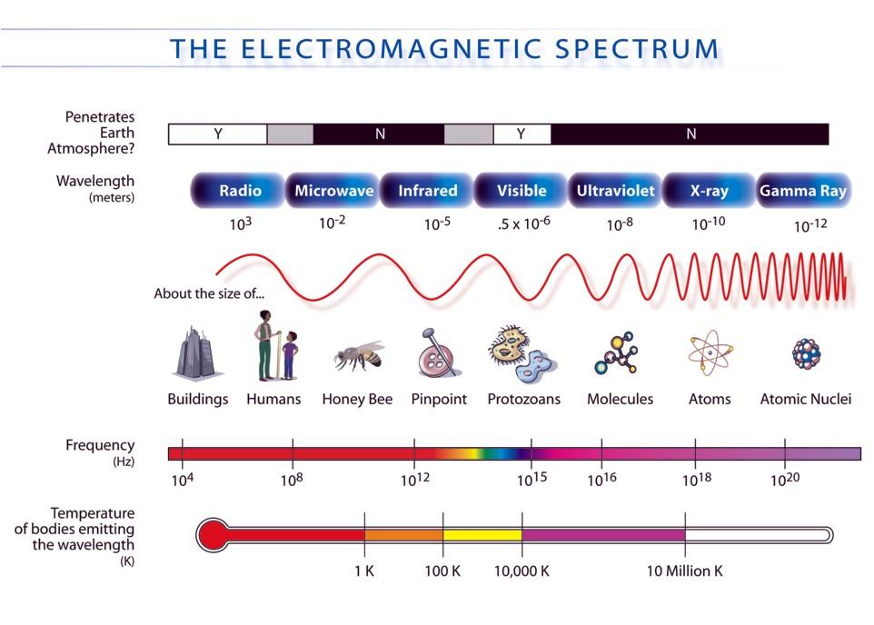
2 Outline Activity Introduction Electromagnetic Spectrum Visible Light Light Microscope AFM Scanning Electron Microscopy Near-Field Microscopy
3 What is it?


4 What is it?
5 What is it?
6 What is it?
7 What is it?
8 What is it?
9 What is it?
10 What is it?
11

12 Visible Light Diagram Source (bottom): Molecular Expressions Optical Microscopy Primer,


13 Light Microscopy Microscopy Issues Magnification Resolution Contrast Brightness Focus Adjusting the contrast of an image Diagram Source (left and center): Molecular Expressions Optical Microscopy Primer,


14 Light Microscopy Brightness Contrast Focus Resolution Diagram Source: How Stuff Works,


: P. M. Fishbane, S.")

: Molecular Expressions Optical")
15 Resolution A smaller wavelength leads to better resolution! The interference pattern of single-slit diffraction and the relative intensities of such a pattern Light from two sources passes through an aperture If you are viewing something 5 cm away the maximum resolution of your eye is mm Diagram Source (top two): P. M. Fishbane, S. Gasiorowicz, and S.T. Thornton, Physics for Scientists and Engineers, Volume I (Prentice Hall, Upper Saddle River, 1996). Diagram Source (bottom two): Molecular Expressions Optical Microscopy Primer,


:")


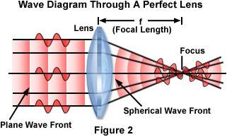
16 Lenses Diagram Source (left, top, lower right): Molecular Expressions Optical Microscopy Primer,


: Molecular")

17 Light Microscope eyepiece Intermediate image Tube lens objective specimen condenser Diagram Source (all): Molecular Expressions Optical Microscopy Primer,
 0.")


18 Beating the Diffraction Limit d min = λ NA d min ( visible) μm Alternatives Scanning Tunneling Microscope Why use visible light? Contrast Easier Sample Preparation Atomic Force Microscope Scanning Electron Microscope Transmission Electron Microscope Near-Field Imaging

 An ipod")

19 How small is a nanometer? Atom: 1 x m Cell: 1 x 10⁻⁵ m ( m) ( m) 1 nanometer is m (1 billionth of a meter) An ipod Nano is about 7 million nanometers thick A human hair is about 100,000 nanometers thick ipod Nano thickness : 7 x 10⁻³ m (~0.007 m)


20 Atomic Force Microscopy Resolution ~ 1 nm How it Works A cantilever probe is scanned over the surface of a sample. As the probe scans the surface it is deflected by surface features. This deflection is measured by laser light reflected off the probe. Advantages High Resolution 3D Image Disadvantages Small scan size Slow scan speed


21 Scanning Electron Microscope (SEM) SEM image of a snow crystal Resolution~10 s of nm How it Works A beam of electrons is scanned over the sample. These electrons cause the sample to emit electrons. It is these emitted electrons that are detected to produce the image. Advantages Large scan area 3D images Disadvantages Sample must be conductive Sample placed in a vacuum Image Source: Wikipedia,

22 What is it? Ant head Pollen Asbestos fibers Spider Web Velcro
23 What is it? Needle and thread Human Hair Popped Popcorn
 197 E. A. Ash and G. Nicholls (3) Passed microwaves (3 cm) through 1.5 mm aperture Scanned over grating and were able to resolve 0.5 mm lines and 0.")
24 Near Field Imaging History 198 Synge Idea (6) Strong light source behind thin metal film 100 nm diameter hole to illuminate biological sample Sample less than 100 nm away from source Discusses ideas in letters to Albert Einstein (7) 197 E. A. Ash and G. Nicholls (3) Passed microwaves (3 cm) through 1.5 mm aperture Scanned over grating and were able to resolve 0.5 mm lines and 0.5 mm gaps in grating 1984 Pohl, Denk, Duerig (IBM) (SNOM) Lewis group (Cornell) (NSOM) Subwavelength aperture at apex of sharp transparent probe tip that is coated with metal Diagram Source: Molecular Expressions Optical Microscopy Primer,
25 Evanescent Waves ( ) 1 1 sin sin θ θ n n = = 1 1 sin n n θ c ( ) t z k x k i z x e E ω r ( ) t z k x k i z x e E ω + r ( ) k n k k z x = + ( ) k n k k z x = + ( ) sin θ β k n k k z z = = = ( ) cos θ k k x = n ( ) ( ) sin cos θ θ = n n n n ( ) ( ) t i z x n n k in e E ω θ θ sin sin ( ) t z i x e E ω β γ + ( ) sin = n n k n θ γ Diagram Source: K. Iizuka, Elements of Photonics: In Free Space and Special Media, Volume 1 (John Wiley & Sons, New York, 00). (4) Total Internal Reflection Wave vectors propagating in k space
26 Evanescent Waves Evanescent Waves on a Corrugated Metal Surface Evanescent Waves on an Array of Metal Pins k x + kz = To satisfy boundary conditions: k xn ( nk) This can be re-written as: π π = m λ d λzm m = k zm d π = m d The value of k xn is imaginary for high values of m and the waves are evanescent waves d c = λ Above d c k x is always imaginary and all the waves in x are evanescent waves. Diagram Source: K. Iizuka, Elements of Photonics: In Free Space and Special Media, Volume 1 (John Wiley & Sons, New York, 00).
 Scanning tunneling optical microscope (d) oblique collection (e) oblique illumination (f) Dark field Diagram (left) Source: M. A. Paesler and P. J.")
27 Modes of Near Field Imaging NSOM Configurations Different types of scanning near field optical microscopes (c) collection/illumination (a) collection (b) illumination (a) Aperture NSOM (b) Aperture-less NSOM (c) Scanning tunneling optical microscope (d) oblique collection (e) oblique illumination (f) Dark field Diagram (left) Source: M. A. Paesler and P. J. Moyer, Near Field Optics: Theory, Instrumentation, and Applications (John Wiley & Sons, New York, 1996). Diagram (right) Source: B. Hecht et al., J. Chem. Phys. 11, 7761 (000).

. Diagram (right) Source: Molecular Expressions Optical Microscopy Primer, http://micro.magnet.fsu.edu/primer/index.")
28 NSOM Setup Standard NSOM Setup (a) Illumination Tips (8) Heating and pulling method - Optical fiber is heated with CO laser and pulled on both sides of heated area Chemical etching method - Hydrofluoric acid used to etch glass fiber Fiber coated with metal Nanoparticle (Tip Enhanced) (b) Collection and Redistribution (c) Detection Diagram (left) Source: B. Hecht et al., J. Chem. Phys. 11, 7761 (000). Diagram (right) Source: Molecular Expressions Optical Microscopy Primer,
, (d) SEM close-up of the aperture region Problems (9) Difficult to create smooth aluminum coating on nanometer scale Flat ends")
. Diagram (right) Source: Molecular Expressions Optical Microscopy Primer, http://micro.magnet.fsu.edu/primer/index.")
29 Aperture NSOM Resolution: nm Aluminum-coated aperture probes 300 nm (a), (b) prepared by pulling (c), (d) prepared by etching 300 nm (a), (c) macroscopic shape, SEM and optical image (b), (d) SEM close-up of the aperture region Problems (9) Difficult to create smooth aluminum coating on nanometer scale Flat ends of the probes are not good for high resolution topographic imaging Absorption of light by metal coating causes significant heating Diagram (left) Source: B. Hecht et al., J. Chem. Phys. 11, 7761 (000). Diagram (right) Source: Molecular Expressions Optical Microscopy Primer,

30 Tip-Enhanced NSOM Schematic of experimental setup for tip-enhanced near field Induced surface charge density in metal probe Resolution: 10-0 nm The incident field should be polarized along the tip axis to maximize field enhancement Need large near field enhancement so the signal can be detected in the far field Left: Incident wave polarized perpendicular to tip axis Right: Incident wave polarized along tip axis Causes for Enhanced Electric Field: (10) Electrostatic lightning rod effect (depends on geometry) Surface plasmon resonances (depend on excitation wavelength and geometry) Diagram (left) Source: A. Hartschuh, M. R. Beversluis, A. Bouhelier, and L. Novotny, Phil. Trans. R. Soc. Lond. A. 36, 807 (004). Diagram (right) Source: L. Novotny, R. X. Bian, and X. S. Xie, Phys. Rev. Lett. 79, 645 (1997).
 NSOM image Diagram")

31 Near Field Images a b SRAM: 10 x 10 µm (a) AFM topography image, (b) NSOM image Diagram Source: Nanonics Imaging Ltd.
 AFM image, (b) NSOM image")

32 Near Field Images a b SRAM after Chemical Mechanical Polishing: 1 x 1 µm (a) AFM image, (b) NSOM image Diagram Source: Nanonics Imaging Ltd. (8)
33 Conclusion There are many factors that affect images obtained with a conventional light microscope Magnification Brightness Contrast Focus Resolution The diffraction of light waves limits the maximum resolution attainable with conventional light microscopy. Electron microscopy allows researchers to obtain high resolution images of a sample. Near-field microscopy involves illuminating a sample with visible light and scanning the sample with a probe that is positioned close to the surface. Near-field imaging techniques allow researchers produce images with a resolution better than 100 nm.
34 References 1. Molecular Expressions Optical Microscopy Primer, How Stuff Works, 3. P. M. Fishbane, S. Gasiorowicz, and S.T. Thornton, Physics for Scientists and Engineers, Volume I (Prentice Hall, Upper Saddle River, 1996). 4. Wikipedia, 5. K. Iizuka, Elements of Photonics: In Free Space and Special Media, Volume 1 (John Wiley & Sons, New York, 00). 6. B. Hecht et al., J. Chem. Phys. 11, 7761 (000). 7. M. A. Paesler and P. J. Moyer, Near Field Optics: Theory, Instrumentation, and Applications (John Wiley & Sons, New York, 1996). 8. P. N. Prasad, Nanophotonics (John Wiley & Sons, Hoboken, 004). 9. E. J. Sanchez, L. Novotny, and X. S. Xie, Phys. Rev. Lett. 8, 4014 (1999). 10. A. Hartschuh, M. R. Beversluis, A. Bouhelier, and L. Novotny, Phil. Trans. R. Soc. Lond. A. 36, 807 (004). 11. L. Novotny, R. X. Bian, and X. S. Xie, Phys. Rev. Lett. 79, 645 (1997). 1. Nanonics Imaging Ltd.
specular diffuse reflection.
 Lesson 8 Light and Optics The Nature of Light Properties of Light: Reflection Refraction Interference Diffraction Polarization Dispersion and Prisms Total Internal Reflection Huygens s Principle The Nature
Physics Midterm I
 Phys121 - February 6, 2009 1 Physics 121 - Midterm I Last Name First Name Student Number Signature Tutorial T.A. (circle one): Ricky Chu Firuz Demir Maysam Emadi Alireza Jojjati Answer ALL 10 questions.
Lab 12 - Interference-Diffraction of Light Waves
 Lab 12 - Interference-Diffraction of Light Waves Equipment and Safety: No special safety equipment is required for this lab. Do not look directly into the laser. Do not point the laser at other people.
Intermediate Physics PHYS102
 Intermediate Physics PHYS102 Dr Richard H. Cyburt Assistant Professor of Physics My office: 402c in the Science Building My phone: (304) 384-6006 My email: rcyburt@concord.edu My webpage: www.concord.edu/rcyburt
PHY 112: Light, Color and Vision. Lecture 11. Prof. Clark McGrew Physics D 134. Review for Exam. Lecture 11 PHY 112 Lecture 1
 PHY 112: Light, Color and Vision Lecture 11 Prof. Clark McGrew Physics D 134 Review for Exam Lecture 11 PHY 112 Lecture 1 From Last Time Lenses Ray tracing a Convex Lens Announcements The midterm is Thursday
Ray Optics I. Last time, finished EM theory Looked at complex boundary problems TIR: Snell s law complex Metal mirrors: index complex
 Phys 531 Lecture 8 20 September 2005 Ray Optics I Last time, finished EM theory Looked at complex boundary problems TIR: Snell s law complex Metal mirrors: index complex Today shift gears, start applying
Supplementary Figure 1 Optimum transmissive mask design for shaping an incident light to a desired
 Supplementary Figure 1 Optimum transmissive mask design for shaping an incident light to a desired tangential form. (a) The light from the sources and scatterers in the half space (1) passes through the
Physics 214 Midterm Fall 2003 Form A
 1. A ray of light is incident at the center of the flat circular surface of a hemispherical glass object as shown in the figure. The refracted ray A. emerges from the glass bent at an angle θ 2 with respect
12/7/2012. Biomolecular structure. Diffraction, X-ray crystallography, light- and electron microscopy. CD spectroscopy, mass spectrometry
 phase difference at a given distance constructive/destructive interference Biomolecular structure. Diffraction, X-ray crystallography, light- and electron microscopy. CD spectroscopy, mass spectrometry
E x Direction of Propagation. y B y
 x E x Direction of Propagation k z z y B y An electromagnetic wave is a travelling wave which has time varying electric and magnetic fields which are perpendicular to each other and the direction of propagation,
Exam Microscopic Measurement Techniques 4T th of April, 2008
 Exam Microscopic Measurement Techniques 4T300 29 th of April, 2008 Name / Initials: Ident. #: Education: This exam consists of 5 questions. Questions and sub questions will be rewarded with the amount
Chapter 24. Wave Optics
 Chapter 24 Wave Optics Wave Optics The wave nature of light is needed to explain various phenomena Interference Diffraction Polarization The particle nature of light was the basis for ray (geometric) optics
A SUPER-RESOLUTION MICROSCOPY WITH STANDING EVANESCENT LIGHT AND IMAGE RECONSTRUCTION METHOD
 A SUPER-RESOLUTION MICROSCOPY WITH STANDING EVANESCENT LIGHT AND IMAGE RECONSTRUCTION METHOD Hiroaki Nishioka, Satoru Takahashi Kiyoshi Takamasu Department of Precision Engineering, The University of Tokyo,
Near Field Observation of a Refractive Index Grating and a Topographical Grating by an Optically Trapped Gold Particle
 Near Field Observation of a Refractive Index Grating and a Topographical Grating by an Optically Trapped Gold Particle Hiroo UKITA and Hirotaka UEMI Ritsumeikan University, Kusatsu-shi, Shiga, 2 Japan
61 (6) ISSN X,
 ISSN X,") Barrio, J. and Han, T. P J and Lamela, J. and de las Heras, C. and Lifante, G. and Sánchez-Alejo, M. A. and Camarillo, E. and Jaque, F. (2015) SNOM characterization of a potential low cost thin gold coated
Barrio, J. and Han, T. P J and Lamela, J. and de las Heras, C. and Lifante, G. and Sánchez-Alejo, M. A. and Camarillo, E. and Jaque, F. (2015) SNOM characterization of a potential low cost thin gold coated
AP* Optics Free Response Questions
 AP* Optics Free Response Questions 1978 Q5 MIRRORS An object 6 centimeters high is placed 30 centimeters from a concave mirror of focal length 10 centimeters as shown above. (a) On the diagram above, locate
EM Waves Practice Problems
 PSI AP Physics 2 Name 1. Sir Isaac Newton was one of the first physicists to study light. What properties of light did he explain by using the particle model? 2. Who was the first person who was credited
Chapter 24. Wave Optics. Wave Optics. The wave nature of light is needed to explain various phenomena
 Chapter 24 Wave Optics Wave Optics The wave nature of light is needed to explain various phenomena Interference Diffraction Polarization The particle nature of light was the basis for ray (geometric) optics
Optics Vac Work MT 2008
 Optics Vac Work MT 2008 1. Explain what is meant by the Fraunhofer condition for diffraction. [4] An aperture lies in the plane z = 0 and has amplitude transmission function T(y) independent of x. It is
NEW OPTICAL MEASUREMENT TECHNIQUE FOR SI WAFER SURFACE DEFECTS USING ANNULAR ILLUMINATION WITH CROSSED NICOLS
 NEW OPTICAL MEASUREMENT TECHNIQUE FOR SI WAFER SURFACE DEFECTS USING ANNULAR ILLUMINATION WITH CROSSED NICOLS Satoru Takahashi 1, Takashi Miyoshi 1, Yasuhiro Takaya 1, and Takahiro Abe 2 1 Department of
PHYS2002 Spring 2012 Practice Exam 3 (Chs. 25, 26, 27) Constants
 Constants") PHYS00 Spring 01 Practice Exam 3 (Chs. 5, 6, 7) Constants m m q q p e ε = 8.85 o o p e = 1.67 = 9.11 7 9 7 31 = + 1.60 = 1.60 μ = 4π k = 8.99 g = 9.8 m/s 1 kg 19 19 C kg T m/a N m C / N m C / C 1. A convex
PHYS00 Spring 01 Practice Exam 3 (Chs. 5, 6, 7) Constants m m q q p e ε = 8.85 o o p e = 1.67 = 9.11 7 9 7 31 = + 1.60 = 1.60 μ = 4π k = 8.99 g = 9.8 m/s 1 kg 19 19 C kg T m/a N m C / N m C / C 1. A convex
Textbook Reference: Physics (Wilson, Buffa, Lou): Chapter 24
: Chapter 24") AP Physics-B Physical Optics Introduction: We have seen that the reflection and refraction of light can be understood in terms of both rays and wave fronts of light. Light rays are quite compatible with
AP Physics-B Physical Optics Introduction: We have seen that the reflection and refraction of light can be understood in terms of both rays and wave fronts of light. Light rays are quite compatible with
Chapter 36. Image Formation
 Chapter 36 Image Formation Apr 22, 2012 Light from distant things We learn about a distant thing from the light it generates or redirects. The lenses in our eyes create images of objects our brains can
Models of Light The wave model: The ray model: The photon model:
 Models of Light The wave model: under many circumstances, light exhibits the same behavior as sound or water waves. The study of light as a wave is called wave optics. The ray model: The properties of
Wave Optics. April 11, 2014 Chapter 34 1
 Wave Optics April 11, 2014 Chapter 34 1 Announcements! Exam tomorrow! We/Thu: Relativity! Last week: Review of entire course, no exam! Final exam Wednesday, April 30, 8-10 PM Location: WH B115 (Wells Hall)
Formulas of possible interest
 Name: PHYS 3410/6750: Modern Optics Final Exam Thursday 15 December 2011 Prof. Bolton No books, calculators, notes, etc. Formulas of possible interest I = ɛ 0 c E 2 T = 1 2 ɛ 0cE 2 0 E γ = hν γ n = c/v
Unit 5.C Physical Optics Essential Fundamentals of Physical Optics
 Unit 5.C Physical Optics Essential Fundamentals of Physical Optics Early Booklet E.C.: + 1 Unit 5.C Hwk. Pts.: / 25 Unit 5.C Lab Pts.: / 20 Late, Incomplete, No Work, No Units Fees? Y / N 1. Light reflects
Chapter 24. Wave Optics
 Chapter 24 Wave Optics hitt1 An upright object is located a distance from a convex mirror that is less than the mirror's focal length. The image formed by the mirror is (1) virtual, upright, and larger
CORRELATION BETWEEN SCANNING TUNNELING MICROSCOPY (STM)-INDUCED PHOTON MAP AND THE STM TOPOGRAPHY OF NANOMETER-SIZE METAL PARTICLES
-INDUCED PHOTON MAP AND THE STM TOPOGRAPHY OF NANOMETER-SIZE METAL PARTICLES") Scanning Microscopy Vol. 12, No. 1, 1998 (Pages 113-118) 0891-7035/98$5.00+.25 Scanning Microscopy International, Chicago (AMF Nanometer-size O Hare), IL 60666 metal USA particles CORRELATION BETWEEN SCANNING
Scanning Microscopy Vol. 12, No. 1, 1998 (Pages 113-118) 0891-7035/98$5.00+.25 Scanning Microscopy International, Chicago (AMF Nanometer-size O Hare), IL 60666 metal USA particles CORRELATION BETWEEN SCANNING
Phy 133 Section 1: f. Geometric Optics: Assume the rays follow straight lines. (No diffraction). v 1 λ 1. = v 2. λ 2. = c λ 2. c λ 1.
. v 1 λ 1. = v 2. λ 2. = c λ 2. c λ 1.") Phy 133 Section 1: f Geometric Optics: Assume the rays follow straight lines. (No diffraction). Law of Reflection: θ 1 = θ 1 ' (angle of incidence = angle of reflection) Refraction = bending of a wave
Phy 133 Section 1: f Geometric Optics: Assume the rays follow straight lines. (No diffraction). Law of Reflection: θ 1 = θ 1 ' (angle of incidence = angle of reflection) Refraction = bending of a wave
Chapter 24. Wave Optics. Wave Optics. The wave nature of light is needed to explain various phenomena
 Chapter 24 Wave Optics Wave Optics The wave nature of light is needed to explain various phenomena Interference Diffraction Polarization The particle nature of light was the basis for ray (geometric) optics
Ray Optics. Lecture 23. Chapter 23. Physics II. Course website:
 Lecture 23 Chapter 23 Physics II Ray Optics Course website: http://faculty.uml.edu/andriy_danylov/teaching/physicsii Let s finish talking about a diffraction grating Diffraction Grating Let s improve (more
New topic: Diffraction only one slit, but wide. From Last time. Huygen s principle. Overlapping diffraction patterns. Diffraction from other objects
 New topic: Diffraction only one slit, but wide From Last time Two-source interference: Interference-like pattern from a single slit. For a slit: a θ central width ~ 2 Diffraction grating Week3HW on Mastering
Chapter 8: Physical Optics
 Chapter 8: Physical Optics Whether light is a particle or a wave had puzzled physicists for centuries. In this chapter, we only analyze light as a wave using basic optical concepts such as interference
Chapter 37. Wave Optics
 Chapter 37 Wave Optics Wave Optics Wave optics is a study concerned with phenomena that cannot be adequately explained by geometric (ray) optics. Sometimes called physical optics These phenomena include:
SPECTRUM. The world s first fully automated Raman AFM. AFM - confocal Raman - SNOM - TERS AFM KPFM. Raman. AFM-Raman characterization of PS-PVAC
 Raman KPFM AFM AFM-Raman characterization of PS-PVAC polymer blend film SPECTRUM The world s first fully automated Raman AFM AFM - confocal Raman - SNOM - TERS The first fully integrated & automated AFM
UNIT VI OPTICS ALL THE POSSIBLE FORMULAE
 58 UNIT VI OPTICS ALL THE POSSIBLE FORMULAE Relation between focal length and radius of curvature of a mirror/lens, f = R/2 Mirror formula: Magnification produced by a mirror: m = - = - Snell s law: 1
PHYS:1200 LECTURE 32 LIGHT AND OPTICS (4)
") 1 PHYS:1200 LECTURE 32 LIGHT AND OPTICS (4) The first three lectures in this unit dealt with what is for called geometric optics. Geometric optics, treats light as a collection of rays that travel in straight
1 PHYS:1200 LECTURE 32 LIGHT AND OPTICS (4) The first three lectures in this unit dealt with what is for called geometric optics. Geometric optics, treats light as a collection of rays that travel in straight
PHYSICS. Chapter 33 Lecture FOR SCIENTISTS AND ENGINEERS A STRATEGIC APPROACH 4/E RANDALL D. KNIGHT
 PHYSICS FOR SCIENTISTS AND ENGINEERS A STRATEGIC APPROACH 4/E Chapter 33 Lecture RANDALL D. KNIGHT Chapter 33 Wave Optics IN THIS CHAPTER, you will learn about and apply the wave model of light. Slide
Interference, Diffraction & Polarization
 Interference, Diffraction & Polarization PHY232 Remco Zegers zegers@nscl.msu.edu Room W109 cyclotron building http://www.nscl.msu.edu/~zegers/phy232.html light as waves so far, light has been treated as
Diffraction Diffraction occurs when light waves pass through an aperture Huygen's Principal: each point on wavefront acts as source of another wave
 Diffraction Diffraction occurs when light waves pass through an aperture Huygen's Principal: each point on wavefront acts as source of another wave If light coming from infinity point source at infinity
Chapter 37. Interference of Light Waves
 Chapter 37 Interference of Light Waves Wave Optics Wave optics is a study concerned with phenomena that cannot be adequately explained by geometric (ray) optics These phenomena include: Interference Diffraction
Interference. Electric fields from two different sources at a single location add together. The same is true for magnetic fields at a single location.
 Interference Electric fields from two different sources at a single location add together. The same is true for magnetic fields at a single location. Thus, interacting electromagnetic waves also add together.
Physics 1C, Summer 2011 (Session 1) Practice Midterm 2 (50+4 points) Solutions
 Practice Midterm 2 (50+4 points) Solutions") Physics 1C, Summer 2011 (Session 1) Practice Midterm 2 (50+4 points) s Problem 1 (5x2 = 10 points) Label the following statements as True or False, with a one- or two-sentence explanation for why you chose
Physics 1C, Summer 2011 (Session 1) Practice Midterm 2 (50+4 points) s Problem 1 (5x2 = 10 points) Label the following statements as True or False, with a one- or two-sentence explanation for why you chose
Chapter 24. Wave Optics
 Chapter 24 Wave Optics Diffraction Huygen s principle requires that the waves spread out after they pass through slits This spreading out of light from its initial line of travel is called diffraction
Lecture 4 Recap of PHYS110-1 lecture Physical Optics - 4 lectures EM spectrum and colour Light sources Interference and diffraction Polarization
 Lecture 4 Recap of PHYS110-1 lecture Physical Optics - 4 lectures EM spectrum and colour Light sources Interference and diffraction Polarization Lens Aberrations - 3 lectures Spherical aberrations Coma,
Three-dimensional imaging of 30-nm nanospheres using immersion interferometric lithography
 Three-dimensional imaging of 30-nm nanospheres using immersion interferometric lithography Jianming Zhou *, Yongfa Fan, Bruce W. Smith Microelectronics Engineering Department, Rochester Institute of Technology,
PHYSICS. Chapter 34 Lecture FOR SCIENTISTS AND ENGINEERS A STRATEGIC APPROACH 4/E RANDALL D. KNIGHT
 PHYSICS FOR SCIENTISTS AND ENGINEERS A STRATEGIC APPROACH 4/E Chapter 34 Lecture RANDALL D. KNIGHT Chapter 34 Ray Optics IN THIS CHAPTER, you will learn about and apply the ray model of light Slide 34-2
Surface Plasmon and Nano-metallic layout simulation with OptiFDTD
 Surface Plasmon and Nano-metallic layout simulation with OptiFDTD 1. Lorentz_Drude Model and Surface Plasma wave Metallic photonic materials demonstrate unique properties due to the existence on metals
Chapter 25. Wave Optics
 Chapter 25 Wave Optics Interference Light waves interfere with each other much like mechanical waves do All interference associated with light waves arises when the electromagnetic fields that constitute
Phase. E = A sin(2p f t+f) (wave in time) or E = A sin(2p x/l +f) (wave in space)
 (wave in time) or E = A sin(2p x/l +f) (wave in space)") Interference When two (or more) waves arrive at a point (in space or time), they interfere, and their amplitudes may add or subtract, depending on their frequency and phase. 1 Phase E = A sin(2p f t+f)
Interference When two (or more) waves arrive at a point (in space or time), they interfere, and their amplitudes may add or subtract, depending on their frequency and phase. 1 Phase E = A sin(2p f t+f)
The sources must be coherent. This means they emit waves with a constant phase with respect to each other.
 CH. 24 Wave Optics The sources must be coherent. This means they emit waves with a constant phase with respect to each other. The waves need to have identical wavelengths. Can t be coherent without this.
Michelson Interferometer
 Michelson Interferometer The Michelson interferometer uses the interference of two reflected waves The third, beamsplitting, mirror is partially reflecting ( half silvered, except it s a thin Aluminum
Chapter 2: Wave Optics
 Chapter : Wave Optics P-1. We can write a plane wave with the z axis taken in the direction of the wave vector k as u(,) r t Acos tkzarg( A) As c /, T 1/ and k / we can rewrite the plane wave as t z u(,)
Unit I Light and Optics
 Unit I Light and Optics Outline By the time you finish this, you should understand the following aspects of our experiment: 1) Why you produce a grating pattern when you cross two laser beams. 2) What
Transmission Electron Microscopy 2. Scattering and Diffraction
 Transmission Electron Microscopy 2. Scattering and Diffraction EMA 6518 Spring 2007 01/07 Outline Why are we interested in electron scattering? Terminology of scattering The characteristics of electron
AP Physics Problems -- Waves and Light
 AP Physics Problems -- Waves and Light 1. 1975-4 (Physical Optics) a. Light of a single wavelength is incident on a single slit of width w. (w is a few wavelengths.) Sketch a graph of the intensity as
Control of Light. Emmett Ientilucci Digital Imaging and Remote Sensing Laboratory Chester F. Carlson Center for Imaging Science 8 May 2007
 Control of Light Emmett Ientilucci Digital Imaging and Remote Sensing Laboratory Chester F. Carlson Center for Imaging Science 8 May 007 Spectro-radiometry Spectral Considerations Chromatic dispersion
Physical Optics. You can observe a lot just by watching. Yogi Berra ( )
") Physical Optics You can observe a lot just by watching. Yogi Berra (1925-2015) OBJECTIVES To observe some interference and diffraction phenomena with visible light. THEORY In a previous experiment you
Physical Optics You can observe a lot just by watching. Yogi Berra (1925-2015) OBJECTIVES To observe some interference and diffraction phenomena with visible light. THEORY In a previous experiment you
f. (5.3.1) So, the higher frequency means the lower wavelength. Visible part of light spectrum covers the range of wavelengths from
 So, the higher frequency means the lower wavelength. Visible part of light spectrum covers the range of wavelengths from") Lecture 5-3 Interference and Diffraction of EM Waves During our previous lectures we have been talking about electromagnetic (EM) waves. As we know, harmonic waves of any type represent periodic process
Lecture 5-3 Interference and Diffraction of EM Waves During our previous lectures we have been talking about electromagnetic (EM) waves. As we know, harmonic waves of any type represent periodic process
An Inspection and Measurement Technology Platform Leading the Way to More Advanced Manufacturing
 Hitachi Review Vol. 65 (2016), No. 7 277 Featured Articles An Inspection and Measurement Technology Platform Leading the Way to More Advanced Manufacturing Takenori Hirose Maki Tanaka Hiroyuki Nakano,
2/26/2016. Chapter 23 Ray Optics. Chapter 23 Preview. Chapter 23 Preview
 Chapter 23 Ray Optics Chapter Goal: To understand and apply the ray model of light. Slide 23-2 Chapter 23 Preview Slide 23-3 Chapter 23 Preview Slide 23-4 1 Chapter 23 Preview Slide 23-5 Chapter 23 Preview
Phys 102 Lecture 17 Introduction to ray optics
 Phys 102 Lecture 17 Introduction to ray optics 1 Physics 102 lectures on light Light as a wave Lecture 15 EM waves Lecture 16 Polarization Lecture 22 & 23 Interference & diffraction Light as a ray Lecture
Diffraction. Factors that affect Diffraction
 Diffraction What is one common property the four images share? Diffraction: Factors that affect Diffraction TELJR Publications 2017 1 Young s Experiment AIM: Does light have properties of a particle? Or
MultiView 2000 TM. The First Tip and Sample Scanning Probe Microscope. The Next Evolution in SPM. The Next Evolution in SPM
 MultiView 2000 TM The First Tip and Sample Scanning Probe Microscope MultiView 2000 TM Using Two Award Winning Nanonics 3D FlatScan Stages MultiView 2000TM Top-View (Top) and open position (Bottom). The
Figure 1: Derivation of Bragg s Law
 What is Bragg s Law and why is it Important? Bragg s law refers to a simple equation derived by English physicists Sir W. H. Bragg and his son Sir W. L. Bragg in 1913. This equation explains why the faces
Coherent Gradient Sensing Microscopy: Microinterferometric Technique. for Quantitative Cell Detection
 Coherent Gradient Sensing Microscopy: Microinterferometric Technique for Quantitative Cell Detection Proceedings of the SEM Annual Conference June 7-10, 010 Indianapolis, Indiana USA 010 Society for Experimental
Chapter 36. Diffraction. Copyright 2014 John Wiley & Sons, Inc. All rights reserved.
 Chapter 36 Diffraction Copyright 36-1 Single-Slit Diffraction Learning Objectives 36.01 Describe the diffraction of light waves by a narrow opening and an edge, and also describe the resulting interference
LECTURE 14 PHASORS & GRATINGS. Instructor: Kazumi Tolich
 LECTURE 14 PHASORS & GRATINGS Instructor: Kazumi Tolich Lecture 14 2 Reading chapter 33-5 & 33-8 Phasors n Addition of two harmonic waves n Interference pattern from multiple sources n Single slit diffraction
Liquid Crystal Displays
 Liquid Crystal Displays Irma Alejandra Nicholls College of Optical Sciences University of Arizona, Tucson, Arizona U.S.A. 85721 iramirez@email.arizona.edu Abstract This document is a brief discussion of
Light and Electromagnetic Waves. Honors Physics
 Light and Electromagnetic Waves Honors Physics Electromagnetic Waves EM waves are a result of accelerated charges and disturbances in electric and magnetic fields (Radio wave example here) As electrons
P recise Eye. High resolution, diffraction-limited f/4.5 optical quality for high precision measurement and inspection.
 High resolution, diffraction-limited f/4.5 optical quality for high precision measurement and inspection. Long working distance makes lighting and handling easier. Compact size. Coaxial lighting available
Chapter 36. Diffraction. Dr. Armen Kocharian
 Chapter 36 Diffraction Dr. Armen Kocharian Diffraction Light of wavelength comparable to or larger than the width of a slit spreads out in all forward directions upon passing through the slit This phenomena
Lecture 4. Physics 1502: Lecture 35 Today s Agenda. Homework 09: Wednesday December 9
 Physics 1502: Lecture 35 Today s Agenda Announcements: Midterm 2: graded soon» solutions Homework 09: Wednesday December 9 Optics Diffraction» Introduction to diffraction» Diffraction from narrow slits»
OPSE FINAL EXAM Fall CLOSED BOOK. Two pages (front/back of both pages) of equations are allowed.
 of equations are allowed.") CLOSED BOOK. Two pages (front/back of both pages) of equations are allowed. YOU MUST SHOW YOUR WORK. ANSWERS THAT ARE NOT JUSTIFIED WILL BE GIVEN ZERO CREDIT. ALL NUMERICAL ANSERS MUST HAVE UNITS INDICATED.
CLOSED BOOK. Two pages (front/back of both pages) of equations are allowed. YOU MUST SHOW YOUR WORK. ANSWERS THAT ARE NOT JUSTIFIED WILL BE GIVEN ZERO CREDIT. ALL NUMERICAL ANSERS MUST HAVE UNITS INDICATED.
2t = (m+ 1 /2) λ = (m+ 1 /2)(λ/n); min, m = 0, 1, 2,... n1 < n2 < n3 2t = m λ = m(λ/n); min, m = 0, 1, 2,... n1 < n2 > n3
 λ = (m+ 1 /2)(λ/n); min, m = 0, 1, 2,... n1 < n2 < n3 2t = m λ = m(λ/n); min, m = 0, 1, 2,... n1 < n2 > n3") PHY1160C Exam #3 July 8, 1997 Possibly useful information: For reflection, θinc = θref For refraction, image equation apparent depth Young s Double Slit: n1 sin θ1 = n2 sin θ2 n = c/v M = h i = d i h o
PHY1160C Exam #3 July 8, 1997 Possibly useful information: For reflection, θinc = θref For refraction, image equation apparent depth Young s Double Slit: n1 sin θ1 = n2 sin θ2 n = c/v M = h i = d i h o
The location of the bright fringes can be found using the following equation.
 What You Need to Know: In the past two labs we ve been thinking of light as a particle that reflects off of a surface or refracts into a medium. Now we are going to talk about light as a wave. If you take
Atomic Force Microscope
 Atomic Force Microscope Preparation Before our first appointment to use the microscope, please watch the video tutorials at https://www.afmworkshop.com/atomic-force-microscope-animated-tutorials/. The
Physical or wave optics
 Physical or wave optics In the last chapter, we have been studying geometric optics u light moves in straight lines u can summarize everything by indicating direction of light using a ray u light behaves
Lab 7 Interference and diffraction
 Prep this lab, as usual. You may paste this entire lab into your notebook, including the data tables. All this should be completed prior to the start of lab on Wednesday, and I will score your completed
PHYS 3410/6750: Modern Optics Midterm #2
 Name: PHYS 3410/6750: Modern Optics Midterm #2 Wednesday 16 November 2011 Prof. Bolton Only pen or pencil are allowed. No calculators or additional materials. PHYS 3410/6750 Fall 2011 Midterm #2 2 Problem
NEAR-IR BROADBAND POLARIZER DESIGN BASED ON PHOTONIC CRYSTALS
 U.P.B. Sci. Bull., Series A, Vol. 77, Iss. 3, 2015 ISSN 1223-7027 NEAR-IR BROADBAND POLARIZER DESIGN BASED ON PHOTONIC CRYSTALS Bogdan Stefaniţă CALIN 1, Liliana PREDA 2 We have successfully designed a
Chapter 7: Geometrical Optics. The branch of physics which studies the properties of light using the ray model of light.
 Chapter 7: Geometrical Optics The branch of physics which studies the properties of light using the ray model of light. Overview Geometrical Optics Spherical Mirror Refraction Thin Lens f u v r and f 2
Review Session 1. Dr. Flera Rizatdinova
 Review Session 1 Dr. Flera Rizatdinova Summary of Chapter 23 Index of refraction: Angle of reflection equals angle of incidence Plane mirror: image is virtual, upright, and the same size as the object
waves_05 ELECTROMAGNETIC WAVES
 waves_05 ELECTROMAGNETIC WAVES 1 waves_05: MINDMAP SUMMARY - ELECTROMAGNETIC WAVES Electromagnetic waves, electromagnetic radiation, speed of light, electromagnetic spectrum, electric field, magnetic field,
College Physics B - PHY2054C
 Young College - PHY2054C Wave Optics: 10/29/2014 My Office Hours: Tuesday 10:00 AM - Noon 206 Keen Building Outline Young 1 2 3 Young 4 5 Assume a thin soap film rests on a flat glass surface. Young Young
1 Laboratory #4: Division-of-Wavefront Interference
 1051-455-0073, Physical Optics 1 Laboratory #4: Division-of-Wavefront Interference 1.1 Theory Recent labs on optical imaging systems have used the concept of light as a ray in goemetrical optics to model
College Physics 150. Chapter 25 Interference and Diffraction
 College Physics 50 Chapter 5 Interference and Diffraction Constructive and Destructive Interference The Michelson Interferometer Thin Films Young s Double Slit Experiment Gratings Diffraction Resolution
Chapter 38. Diffraction Patterns and Polarization
 Chapter 38 Diffraction Patterns and Polarization Diffraction Light of wavelength comparable to or larger than the width of a slit spreads out in all forward directions upon passing through the slit This
10.4 Interference in Thin Films
 0. Interference in Thin Films You have probably noticed the swirling colours of the spectrum that result when gasoline or oil is spilled on water. And you have also seen the colours of the spectrum shining
SESSION 5: INVESTIGATING LIGHT. Key Concepts. X-planation. Physical Sciences Grade In this session we:
 SESSION 5: INVESTIGATING LIGHT Key Concepts In this session we: Explain what light is, where light comes from and why it is important Identify what happens when light strikes the surface of different objects
Diffraction Challenge Problem Solutions
 Diffraction Challenge Problem Solutions Problem 1: Measuring the Wavelength of Laser Light Suppose you shine a red laser through a pair of narrow slits (a = 40 μm) separated by a known distance and allow
Surface Plasmons Edited 6/6/2016 by Stephen Albright & DGH & ETS
 Surface Plasmons Edited 6/6/2016 by Stephen Albright & DGH & ETS Purpose The purpose of this experiment is to measure the dispersion relation of surface plasmons and the electron density in a thin silver
Chapter 24 - The Wave Nature of Light
 Chapter 24 - The Wave Nature of Light Summary Four Consequences of the Wave nature of Light: Diffraction Dispersion Interference Polarization Huygens principle: every point on a wavefront is a source of
Physics 123 Optics Review
 Physics 123 Optics Review I. Definitions & Facts concave converging convex diverging real image virtual image real object virtual object upright inverted dispersion nearsighted, farsighted near point,
Chapter 24. Wave Optics
 Chapter 24 Wave Optics Wave Optics The wave nature of light is needed to explain various phenomena Interference Diffraction Polarization The particle nature of light was the basis for ray (geometric) optics
Chapter 35 &36 Physical Optics
 Chapter 35 &36 Physical Optics Physical Optics Phase Difference & Coherence Thin Film Interference 2-Slit Interference Single Slit Interference Diffraction Patterns Diffraction Grating Diffraction & Resolution
Diffraction. Introduction: Diffraction is bending of waves around an obstacle (barrier) or spreading of waves passing through a narrow slit.
 or spreading of waves passing through a narrow slit.") Introduction: Diffraction is bending of waves around an obstacle (barrier) or spreading of waves passing through a narrow slit. Diffraction amount depends on λ/a proportion If a >> λ diffraction is negligible
Introduction: Diffraction is bending of waves around an obstacle (barrier) or spreading of waves passing through a narrow slit. Diffraction amount depends on λ/a proportion If a >> λ diffraction is negligible
Physics 309 Lab 3. where the small angle approximation has been used. This pattern has maxima at. Y Max. n L /d (2)
") Physics 309 Lab 3 Introduction This will be a lab whose purpose is to give you some hands-on experience with optical interference and diffraction, using small green diode lasers as the light sources. Each
Physics 309 Lab 3 Introduction This will be a lab whose purpose is to give you some hands-on experience with optical interference and diffraction, using small green diode lasers as the light sources. Each
1. (25pts) Answer the following questions. Justify your answers. (Use the space provided below and the next page)
 Answer the following questions. Justify your answers. (Use the space provided below and the next page)") . (25pts) Answer the following questions. Justify your answers. (Use the space provided below and the next page) a). An object (an arrow) is placed as shown in front of each of the following optical instruments.
. (25pts) Answer the following questions. Justify your answers. (Use the space provided below and the next page) a). An object (an arrow) is placed as shown in front of each of the following optical instruments.