University of Minnesota Nano Fabrication Center Standard Operating Procedure
|
|
|
- Gerald Wood
- 6 years ago
- Views:
Transcription
1 Equipment Name: University of Minnesota Nano Fabrication Center Coral Name: hs-scope Revision Number: 1.5 Model: HS200A Revisionist: M. Fisher Location: Bay 1 Date: 9/12/ Description The Hyphenated Systems HS200A optical profiler combines Hyphenated systems Advanced Confocal Microscopy technology with the automation required for high throughput industrial environments. The 200mm platform is extremely versatile and suitable for numerous applications. The nano scale 200A is designed for fast and non-invasive inspection and measurement of the 3-dimensional geometry of probe marks, probe cards, MEMS, micro lenses and similar micro and nano engineered or precision-machined structures. Offering Advanced Confocal Microscopy, bright field and dark field imaging on a single platform, the 200A is an exceptionally versatile and powerful analytical platform. In addition to routine measurements, these systems are especially well suited to measurements of high curvature, steep slope, rough surfaces and for measurements beneath glass windows or engineered semi-transparent films. 2 Safety a HS-200 is outfitted with an extremely intense white light source (EXFO) which may cause permanent injury to the eyes if operated incorrectly. b Never direct the output of the fiber optic light guides into the eyes or onto the skin. c Do not turn the high pressure mercury arc source on before all fiber optic components have been properly connected. 3 Restrictions/Requirements a b No sample greater in height than 25mm. 4 Required Facilities a b 120 V/20A 5 Definitions a See Nikon manual for Nomenclature and functions. b See Hyphenated systems manual for a reference. 6 Setup a None 7 Operating Instructions a Log in to Badger. Characterization and Testing>hs-scope b Log in to hs-scope computer. User name-nfc_users, Password- user_1234 c Turn on the HS-scope power. The switch is located on the back-right side of the microscope base next to the power cord. d Turn on EXFO light source. Wait two minutes for the light source to warm up and stabilize, the LED will stop blinking when the light source is stable. e Open the shutter for the EXFO light source. f Press the confocal button on the top right side of the scope. The confocal yellow LED should be on now. g Double click on HS_V3-2.exe icon. 1

2 h Click on yes for stage to initialize, if you say cancel you will be able to move the stage manually with the x and y knobs on the stage. If you click on no the stage will be in manual mode and you can use the x/y knobs. i Screen is divided into four areas-live image of the surface, icons across the top, top right hand panel (scan and illumination controls), lower right hand panel. j Manual data acquisition involves four basic steps. Define an area of interest (k, l, m, n, and o). Adjust light source intensity and CCD integration time (p, q, and r) Define the vertical sample volume and resolution (s) Click the Acquire button (t) k Position sample on stage under the objectives, using the joy stick. l Define an area of interest using the binocular microscope eye pieces. m Select the desired magnification. 2.5x- numerical aperture 0.075, WD-8.8mm 5x- numerical aperture 0.15, WD-18mm 10x- numerical aperture 0.30, WD-15mm 20x- numerical aperture 0.40, WD-13mm 50x- numerical aperture 0.55, WD-9.8mm 100x- numerical aperture 0.90, WD-1mm n Pull the optical path selection lever out to directing light into the CCD camera. o Click on the microscope icon to obtain a live view. p Using the scan and illumination controls in the image section of the right hand panel to adjust the illumination should be set to maximize the signal while avoiding saturation of the CCD, which is indicated by the presence of pink pixels in the live image. CCD saturation is also indicated when the graph is off scale to right side of the video image. The two slide bars below control the illumination intensity, the upper bar is fine control the lower is coarse control. 2
.")


3 q The signal intensity is adjusted using these two slide controls: CCD integration time (directly below the histogram in the video section in the right hand panel, which should be at least 0.05 seconds and preferably between seconds). The lower slide control can manually be set on the front of the EXFO light source with up down buttons. r s A good strategy is to focus on the brightest layer in the field of view, adjust the illumination intensity, keeping an eye on the image and the intensity histogram as the scan volume is set. Next set the z-scan range, with either the z bar has shown below or the microscope fine focus knob. Using the Z control bar in the scan and illumination control panel adjust the top of the scan range by click on the green arrow button until the image goes out of focus (dark). Then click the top button. This will set the upper limit for the scan range. Then click on the red arrow button until the image goes out of focus (dark). Then click the bottom button. This will set the lower limit for the scan range. Once these settings have been performed, the top, middle, and bottom position should be checked for saturation. t Click the Acquire button. If image is dark, there are four things to check. 1. Optical path selection lever out. 2. Push confocal light button on the microscope (yellow LED will 3

4 light up). 3. Pull the Dark field selection lever out. 4. Open the shutter on the EXFO light source. u Data analysis can be performed on active data or stored data. To open stored data, click on File>open>browse to the file you would like to open. (Note: If the files are contained on rewritable CDs or DVDs, you must first store the data to a local hard disk for the files to be opened.) The main part of the screen will display false color rendering of the surface with a color wedge which serves as a key, translating color to height. (See 2D analysis for more details) v Saving Data: Click on the save icon this will bring up a windows dialogue box. Save data only under user s data section. w Transfer data using the usb port on the front right side of the table. x Use the tools in the correct sections to obtain the measurements you require. y After you have completed your measurements, please reduce the EXFO light source to 0 and close the shutter. If you are the last person of the day (after 5pm) please turn off the EXFO light source. A good rule of thumb, if some is going to use the HS-scope within four hours do not shut off the light source, if not, please shut off the light source. z Turn off the HS-scope power. The switch is located on the back-right side of the microscope base next to the power cord. aa Log off of the HS-scope computer. bb Log off of the HS-scope in coral. 8 Live image screen A Pull down menus File 1. Open- To open existing *.zd3 file. 2. Save as- To save your *.zd3 file. Please save your *.zd3 file to your directory. 4
5 3. Show debug window-shows debug window lower right hand corner. 4. Open surface*.bmp : Opens surface *.BMP. 5. Open intensity *.BMP: Not functional. 6. Save surface *.BMP: Saves surface *.BMP. 7. Save intensity *.BMP : Saves intensity *.BMP Live 1. Camera Live: Toggles live camera on/off. 2. Show Debug: Not functional. 3. Bin 1 (1280x1024): Standard setting. Resolution of live image (1280 x 1024). 4. Bin 2 (640x512): Resolution of live image (640 x 512), smaller data file. 5. Bin 3 (320x256): Resolution of live image (320 x 256), smallest data file. 6. Clear volume Auto 1. Auto Level: Toggles automatic leveling on/off. 2. Auto Reference: Toggles automatic reference on/off. 3. Auto Interpolation: Toggles automatic interpolation on/off. 4. Keep Tools: Saves tool set to a file. Help 1. About: Hyphenated Systems. B Icon below pull down menus. 1. Open File 2. Save as 3. Live image 4. Display slices- The displays the images taken. 5. 2D Processing 6. 3D Display 9 2D Processing screen 5

6 A Pull down menus File 1. Open-To open existing *.zd3 file. 2. Save as- To save your *.zd3 file. Please save your *.zd3 file to your directory. 3. Show debug window- 4. Open surface*.bmp 5. Open intensity *.BMP 6. Save surface *.BMP 7. Save intensity *.BMP View 1. Properties: Toggles right hand properties panel on/off. 2. Tool Selection: Toggles right hand tool selection panel on/off. 3. Display-Toggles right hand display panel on/off. 4. Readout: Toggles right hand readout panel on/off. 5. Roughness: Toggles right hand roughness panel on/off. 6. Threshold: Toggles right hand threshold panel on/off. 7. Zoom: Toggles right hand zoom panel on/off. 8. Calculation: Toggles right calculation panel on/off. 9. Default: Toggles on default panel settings. 10. Show Invalid Data: Dark green/ black/ interpolated 11. Do interpolation- Does interpolation on data set. 2D Tools 1. Points: Points mode Icon Click on the Points Mode icon to evaluate the quality of the scan data. This will bring up a graph of gray scale intensity of the selected pixel on the vertical axis, against scan position along the horizontal axis. Holding down 6
7 the left mouse button as the cursor is moved over the surface, the graph will be continuously updated with the contrast curve for the pixel designated also indicated by a cross displayed on the surface. Releasing the mouse button will freeze the cross and the data for that pixel. The red lines on the following graph represent the algorithm output of surface position at that pixel in the z direction (vertical line) and the maximum gray level at that surface (when it was exactly in focus). 2. Line: Line mode. Display height profile for current cross section. Clicking on the Line Mode icon enables cross sectional analysis of the data. Line properties: None: No averaging is performed. Circular window: An unweighted average of a circular area defined by the line width is used Circular Hann window: A center-weighted circular average is used. Wide line: An unweighted lateral average is used across the line width. Wide line Hann window: A center-weighted lateral average is used 3. Line Roughness: Display line roughness parameters for current cross section. 4. Area: Shows all measurement areas and allows creation of new ones. 5. Level: Shows all leveling areas and allows creation of new ones. 6. Pattern recognition: Shows all pattern recognition tools and allows creation of new ones. 7. All Tools: Show all area tools, pattern recognition tools and line tools on the screen at one time. In this mode, all tools can be moved as a unit, maintaining their relative positions. 8. Roughness options: Roughness and waviness parameters may be changed. 9. Do reference: 10. Do level: 11. Do interpolation: 12. Do manual level: 13. Measure: Record current measurements in the results text box. 14. Recalc Z: Recalculate surface with current algorithm settings. 15. Clear all tools: Deletes all tools. Graph 1. Copy as text: Copies a data set a file. First, a line must be made in line mode, then using copy as text, paste the data set into a notepad document, save document in your folder. 2. Copy as graph: Function does not work. 3. Display: Display has two modes, image only and image and graph. 7
8 4. Show wedge: Displays color wedges in the lower right hand corner of the image window. 5. Show Axes: Displays X and Y axes on the image window. Auto 1. Auto level: Enables automatic leveling. 2. Auto Reference: Subtracts stored reference data from acquired data. 3. Auto Interpolation: Enables automatic interpolation. 4. Keep Tools: When this function is enabled it will save your tool set with the *.zd3 file. Adjusting Surface Calculations (from Hyphenated Systems manual) 1. By default, the surface calculation algorithm finds the surface that shows the largest contrast response with height. For a single opaque, surface this allows the surface to be accurately rendered. In the case of transparent films, however, the surface of interest may not be the one with the largest contrast response. Consider, for instance the case of an isolated photoresist feature on silicon. In the bare silicon region, there is a single contrast response: In the region of the photoresist, however, there are two responses. Some light is scattered from the surface of the photoresist and some from the silicon surface: 8

9 Since the silicon surface shows a greater response than the photoresist surface, this signal is the one traced by the default algorithm. Of course, the silicon seen through the photoresist appears to be at a higher level than the bare silicon because of the refractive index of the photoresist: The interface to be rendered may be controlled by adjusting the parameters of the Surface Calculation. Here, for example we can click on the tab icon at the lop left hand corner of the chard and drag out a cursor, placing it between the two peaks. Now, selecting Above Cursor in the "Surface" pull-down in the Surface Calculation box the detected surface switches to the upper, photoresist, peak. 9
10 Clicking the "Calculate" button re-calculates the entire surface with this new algorithm setting. 10


11 Now the algorithm traces the upper surface and renders the photoresist step correctly. Silicon Nitride Cantilever Beam Surface Calculations The above image is a silicon nitride cantilever beam that is 200um long by 50um wide. The white line at the center of the beam is measuring the deflection of the beam along the length. The above graph gives the deflect vs length for the beam. In graph above the deflection of the beam can be measured at 5.5um at the tip. Below is a 3D image of the beam, to get this image for your data please click the following icon. 11


12 To port this data to an excel file. To the following: 1. Graph>copy as Text. 2. Open excel and import your data. 12

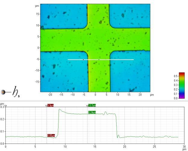
13 10 To make measurement on your sample. After you have acquired an image use points mode to check the signal strength. Using line mode, draw a line from the left side to the right side of your screen. To start the line left click and drag your mouse to the second location and double left mouse button to end the line. If you would like to change the line properties double click on the line mode icon in the tool bar. This will bring up a Line Properties window in the lower right side of you screen. To change the wide of the line see image below. 13

14 Navigation image-provides a means to zoom in on areas within the field-of-view by clicking and dragging to create a zoom box. The main display is zoomed in real time. Any tools present remain in their set positions with their set sizes. Zoom box properties may be accessed by right-clicking the box. Changes to the tool size and position made in the properties box and applied to the navigation image transfer to the main display once the properties box is closed. Measurement cursors- The location of the measurement cursor can be seen below. If you place the mouse cursor over the measure cursor and right click, you will bring a window to define the measurement cursors. See below. 14


15 Measurement cursor properties can be modified in this window. To make a line measurement you would use 50% height as the edge of the line. To set the cursors to snap to these positions, set the type to height, z(%) to 50, click relative and live cursors, then click ok. This sets your cursors to snap to the 50% height of lines or dots. Below are some examples. 3D Display mode- 1um Chrome dots 15

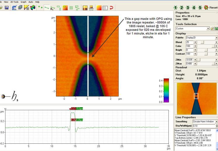

16 Photoresist on silicon showing a small gap (0.5um) 16


17 Metal height measurement using area mode. Metal height measurement using line mode. Silicon etch 17


18 0.9 um hole in a photomask 11 Problems/Troubleshooting 12 Appendix A Stitching Overview 18
LEXT 3D Measuring LASER Microscope
 LEXT 3D Measuring LASER Microscope Warning: This instrument may only be operated by those who have been trained by AAF staff and have read and signed the AAF laboratory policies. A) STARTUP 1. Computer
Standard Operating Procedure of Triboindenter (Hysitron TI 950)
") Standard Operating Procedure of Triboindenter (Hysitron TI 950) I Sample Loading and Preparation DO NOT TOUCH the bottom of transducer and optical microscope. Always place the tall samples on the most
Standard Operating Procedure of Triboindenter (Hysitron TI 950) I Sample Loading and Preparation DO NOT TOUCH the bottom of transducer and optical microscope. Always place the tall samples on the most
University of Minnesota NanoFabrication Center Standard Operating Procedure
 Equipment Name: JEOL SEM Coral Name: jeol-sem Revision Number: 4 Model: JSM-6610LV Revisionist: K. Roberts Location: Area 3 Date: 9/17/2013 1 Description The JSM-6610LV is a scanning electron microscope
Start-up system. Nikon Wide Field Microscope Ee1078. Complete manual
 Start-up system Switch on the power socket located on the floor Switch devices on in the order of: o Mercury lamp control-unit switch on and ignite o Halogen lamp o Incubator control-box o Microscope stand
DSU Start-Up instructions
 DSU Start-Up instructions Always: - start with the 10x objective - properly center the stage around the current objective before changing to another objective - when done, leave the 10x objective in standby
Atomic Force Microscope
 Atomic Force Microscope Preparation Before our first appointment to use the microscope, please watch the video tutorials at https://www.afmworkshop.com/atomic-force-microscope-animated-tutorials/. The
#61-844SW ThermalVision Software Instruction Manual
 ThermalVision Software Instruction Manual ND-7035-1 Page 1 of 23 Contents 1. Installing the ThermalVision software onto a PC... 3 2. Transferring saved images from the camera to the PC.... 3 2.1. Direct
Nikon A1-B Confocal Operating Manual. Start-up. Microscope
 Nikon A1-B Confocal Operating Manual Start-up 1. Turn on Excite 120 LED power supply. a. No need for cool down as for mercury bulb b. Open shutter by pushing down contol knob. c. Adjust intensity by turning
ezimagex2 User s Guide Version 1.0
 ezimagex2 User s Guide Version 1.0 Copyright and Trademark Information The products described in this document are copyrighted works of AVEN, Inc. 2015 AVEN, Inc. 4595 Platt Rd Ann Arbor, MI 48108 All
Motic Images Plus 3.0 ML Software. Windows OS User Manual
 Motic Images Plus 3.0 ML Software Windows OS User Manual Motic Images Plus 3.0 ML Software Windows OS User Manual CONTENTS (Linked) Introduction 05 Menus and tools 05 File 06 New 06 Open 07 Save 07 Save
DV2. Alignment Procedure. Install DV2 on Microscope NOTE: PLEASE READ THE ENTIRE PROCEDURE BEFORE YOU BEGIN ALIGNMENT OF THE DV2. Alignment Procedure
 H I G H - P E R F O R M A N C E E M C C D & C C D C A M E R A S F O R L I F E S C I E N C E S DV2 This document provides a straightforward, step-by-step outline of the alignment procedure for the Photometrics
Click Install View Touch. Installation starts. Click Next. Click Finish.
 1. Please read the instructions carefully. Improper installation may cause permanent damages, which may not be covered by the warranty. 2. Check all the parts in the package against the following parts
The Dektak XT is a 2D contact profilometer used for step height, pitch and surface roughness
 Dektak XT 2D Profilometer Operation Manual The Dektak XT is a 2D contact profilometer used for step height, pitch and surface roughness measurements. Vision 64 application software controls the system
QUANTAX EDS SYSTEM SOP
 QUANTAX EDS SYSTEM SOP December 2017 Energy-Dispersive X-Ray Spectroscopy (EDS, EDX, EDXS or XEDS), is an analytical technique used for the elemental analysis or chemical characterization of a sample.
Prism Starter Guide 1.0 Hoskins Lab Last Modified 03/14/2017 Chris DeCiantis
 Start Up: Upon entering the laser room turn on the wall mounted Laser Power Button by pulling it away from the wall. Turn on Shutter controllers (toggle switch on back of unit). There should be a U in
Operating Procedure for Horiba Raman Microscope
 Operating Procedure for Horiba Raman Microscope SAFETY Be aware of Laser radiation at all times! Do not remove the covers of the instrument. Components are supplied with 110V electric source. Do not touch
MATERIALS PLUS Segmentation Measurement
 Example: Segmentation MATERIALS PLUS Segmentation is a method of image partitioning based on the intensity / gray scale range of its components. Since a phase is detected and its area is estimated on the
Primary Use. Operating Principle
 Primary Use The Leica DVM6 is an optical microscope that has the ability observe samples at a high magnification at a high resolution. The microscope allows users to view their sample with up to a 2350x
Zeiss AxioImager.Z2 Fluorescence Protocol
 Zeiss AxioImager.Z2 Fluorescence Protocol 1) System Startup Please note put sign-up policy. You must inform the facility at least 24 hours beforehand if you can t come; otherwise, you will receive a charge
Exam Microscopic Measurement Techniques 4T th of April, 2008
 Exam Microscopic Measurement Techniques 4T300 29 th of April, 2008 Name / Initials: Ident. #: Education: This exam consists of 5 questions. Questions and sub questions will be rewarded with the amount
Cal-Bay Systems XY Plotter, Time-Base Recorder, Automated Tester. Users Guide. Rev 3.1
 Cal-Bay Systems XY Plotter, Time-Base Recorder, Automated Tester Users Guide Rev 3.1 Contents... 1 Quick Start Guide... 2 Selecting a Test Specification... 3 Clearing Traces... 4 Saving Traces...4 Loading
Visual Physics - Introductory Lab Lab 0
 Your Introductory Lab will guide you through the steps necessary to utilize state-of-the-art technology to acquire and graph data of mechanics experiments. Throughout Visual Physics, you will be using
Heidelberg Pattern Generator SOP
 Heidelberg Pattern Generator SOP Page 1 of 15 Heidelberg Pattern Generator SOP 1. Scope 1.1 This document provides the operating procedures for the Heidelberg Pattern Generator with Version 3.12.5 software.
SmartSoft AES Operator s Guide
 SmartSoft AES Operator s Guide Part No. 702064 Rev. A Physical Electronics USA, PHI, SMART-Tool, SmartSoft, MultiPak and Watcher are trademarks of ULVAC-PHI, Inc. All other trademarks are the property
Contour LS-K Optical Surface Profiler
 Contour LS-K Optical Surface Profiler LightSpeed Focus Variation Provides High-Speed Metrology without Compromise Innovation with Integrity Optical & Stylus Metrology Deeper Understanding More Quickly
Olympus DeltaVision Microscope Start-Up and Shut-Down Instructions.
 DeltaVision Instructions: 1. Start-up (Olympus DV) 2. Basic operation (Olympus DV) 2.1 set-up 2.2 designing and running an experiment 3. Transferring files via FTP 4. Deconvolving files 5. File conversion
XRADIA microxct Manual
 XRADIA microxct Manual Multiscale CT Lab Table of Contents 1. Introduction and Basics 1.1 Instrument Parts 1.2 Powering up the system 1.3 Preparing your sample 2. TXM Controller 2.1 Starting up 2.2 Finding
SI-100 Digital Microscope. User Manual
 SI-100 Digital Microscope User Manual Read this manual before use Keep for future reference Content 1 Introduction... 3 1.1 About The SI-100... 3 1.2 Advantage of SI-100... 3 1.3 Product Specification...
Tutorial 1 Engraved Brass Plate R
 Getting Started With Tutorial 1 Engraved Brass Plate R4-090123 Table of Contents What is V-Carving?... 2 What the software allows you to do... 3 What file formats can be used?... 3 Getting Help... 3 Overview
` EVG 620 MASK ALIGNMENT SYSTEM Bay 1 STANDARD OPERATING PROCEDURE
 ` EVG 620 MASK ALIGNMENT SYSTEM Bay 1 STANDARD OPERATING PROCEDURE Version: 1.0 April-2016 UNIVERSITY OF TEXAS AT ARLINGTON Nanofabrication Research Center (NRC) TABLE OF CONTENTS 1. Introduction...2 1.1
Zeiss Efficient Navigation (ZEN) Blue Edition Standard Operation Protocol
 Blue Edition Standard Operation Protocol") Faculty Core Facility ZEN BLUE 2.3 SOP A-1 Zeiss Efficient Navigation (ZEN) Blue Edition Standard Operation Protocol Faculty Core Facility ZEN BLUE 2.3 SOP A-2 A. Content Overview. 3 Start up. 4 Display
Faculty Core Facility ZEN BLUE 2.3 SOP A-1 Zeiss Efficient Navigation (ZEN) Blue Edition Standard Operation Protocol Faculty Core Facility ZEN BLUE 2.3 SOP A-2 A. Content Overview. 3 Start up. 4 Display
 OPERATING MANUAL H A W K E Y E Portable Digital Slit Lamp 1 INDEX Turning HAWK EYE ON and OFF... p. 3 Automatic shut down... p. 3 Adjusting the illumination intensity... p. 3 Taking pictures... p. 4 Playing
XnView 1.9. a ZOOMERS guide. Introduction...2 Browser Mode... 5 Image View Mode...15 Printing Image Editing...28 Configuration...
 XnView 1.9 a ZOOMERS guide Introduction...2 Browser Mode... 5 Image View Mode...15 Printing... 22 Image Editing...28 Configuration... 36 Written by Chorlton Workshop for hsbp Introduction This is a guide
Slope Stability Problem Session
 Slope Stability Problem Session Stability Analysis of a Proposed Soil Slope Using Slide 5.0 Tuesday, February 28, 2006 10:00 am - 12:00 pm GeoCongress 2006 Atlanta, GA software tools for rock and soil
ZEISS Smartproof 5 Your Integrated Widefield Confocal Microscope for Surface Analysis in Quality Assurance and Quality Control
 Product Information Version 1.0 ZEISS Smartproof 5 Your Integrated Widefield Confocal Microscope for Surface Analysis in Quality Assurance and Quality Control Dedicated Design. Guided Workflow. Trusted
Software for Observation and Measurement SGMMS V2.6. Users Manual
 AFM45-S03-12402 Software for Observation and Measurement SGMMS V2.6 Users Manual SIGMAKOKI Co., LTD. CONTENTS 1 OVERVIEW... - 3-2 BEFORE USE... - 3-2-1 OPERATIONAL ENVIRONMENT...- 3-2-2 INSTALLATION PREPARATION...-
PediGait IP. Users Manual
 PediGait IP Users Manual April 2012 Table of Contents Clients Tab... 2 Open a Client file... 2 Delete Client file(s)... 2 Edit a Client... 3 Add a new client... 3 Add Comments to client files... 4 Profiles
Samples Carolina sample slides (pollen, algae, ). Clean off oil with lens paper then OpticPad around lens (metal not glass) when done.
. Clean off oil with lens paper then OpticPad around lens (metal not glass) when done.") Bi/BE 227 Winter 2018 Assignment #1 Widefield and confocal laser scanning microscopy Schedule: Jan 3: Lecture Jan 3-12: Students get trained on how to use scopes, start on assignment Jan 3-17: Carrying
Bi/BE 227 Winter 2018 Assignment #1 Widefield and confocal laser scanning microscopy Schedule: Jan 3: Lecture Jan 3-12: Students get trained on how to use scopes, start on assignment Jan 3-17: Carrying
XnView Image Viewer. a ZOOMERS guide
 XnView Image Viewer a ZOOMERS guide Introduction...2 Browser Mode... 5 Image View Mode...14 Printing... 22 Image Editing...26 Configuration... 34 Note that this guide is for XnView version 1.8. The current
Advances in Disk Metrology
 Advances in Disk Metrology Robert Kertayasa Zeta Instruments March 2011 www.zeta-inst.com 1909 Concourse Drive San Jose CA 95131 PHONE (408) 577-1888 FAX (408) 577-0588 Agenda Introduction Technology Sample
FlexScan OTDR With SmartAuto and LinkMap
 Test & Inspection FlexScan OTDR With SmartAuto and LinkMap Quick Reference Guide www.aflglobal.com or (800) 321-5298, (603) 528-7780 Controls, Display, Interfaces 1 2 4 8 1. Power button 2. Power jack
How to Measure Wedge. Purpose. Introduction. Tools Needed
 Purpose Optical Wedge Application (OWA) is an add-on analysis tool for measurement of optical wedges in either transmission or reflection. OWA can measure a single part or many parts simultaneously (e.g.
Galileo Standard Series
 Galileo Standard Series AV200 AV300 AV350 EZ200 EZ300 Galileo AV300 The Galileo AV300 combines high-resolution images with the latest software and a precision mechanical platform to deliver 12" x 6" x
Condensed AFM operating instructions:
 Condensed AFM operating instructions: 1. Log onto system at access controller 2. Take the parts you need to mount a probe out of the drawers. You need the appropriate probe holder, tweezers (these are
VXvue User Manual (For Human Use)
") VXvue User Manual (For Human Use) Page 2 of 90 Revision History Version Date Description 1.0 2012-03-20 Initial Release Page 3 of 90 Contents Safety and Regulatory... 8 Safety Notice... 8 1. Introduction...
VXvue User Manual (For Human Use) Page 2 of 90 Revision History Version Date Description 1.0 2012-03-20 Initial Release Page 3 of 90 Contents Safety and Regulatory... 8 Safety Notice... 8 1. Introduction...
Digital Microscopes Zoomy 2.0 Digital Microscope What software/devices will I need to use a Zoomy? Connecting Zoomy 2.0
 Digital Microscopes Zoomy 2.0 Digital Microscope Zoomy 2.0 is a handheld digital microscope that children can use to examine objects. Zoomy plugs into a computer using a built in USB cable. The computer
AUTOFOCUS SENSORS & MICROSCOPY AUTOMATION IR LASER SCANNING CONFOCAL MICROSCOPE IRLC DEEP SEE. Now See Deeper than ever before
 AUTOFOCUS SENSORS & MICROSCOPY AUTOMATION IR LASER SCANNING CONFOCAL MICROSCOPE IRLC DEEP SEE Now See Deeper than ever before Review and inspection of non visible subsurface defects Non visible and subsurface
How to...create a Video VBOX Gauge in Inkscape. So you want to create your own gauge? How about a transparent background for those text elements?
 BASIC GAUGE CREATION The Video VBox setup software is capable of using many different image formats for gauge backgrounds, static images, or logos, including Bitmaps, JPEGs, or PNG s. When the software
User s Guide to the LMD Laser Micro-dissection. System
 User s Guide to the LMD-6000 Laser Micro-dissection System Page 1 Glen MacDonald October 31, 2018 Start-up Procedure for Leica LMD-6000. 1. Turn on mercury lamp by pressing the rocker switch; a. beige
NRF Ellipsometer SOP Revision /19/15 Page 1 of 14. Ellipsometer SOP
 Page 1 of 14 Ellipsometer SOP The J. A. Woollam M88 is a spectroscopic ellipsometer used to measure film thickness and optical constants of transparent/semi-transparent thin films. It uses a Xenon arc
Contents... 1 Installation... 3
 Contents Contents... 1 Installation... 3 1 Prerequisites (check for.net framework 3.5)... 3 Install Doctor Eye... 3 Start Using Doctor Eye... 4 How to create a new user... 4 The Main Window... 4 Open a
FlexScan FS200 OTDR With SmartAuto, FleXpress and LinkMap Quick Reference Guide
 Test & Inspection FlexScan FS200 OTDR With SmartAuto, FleXpress and LinkMap Quick Reference Guide www.aflglobal.com or (800) 321-5298, (603) 528-7780 Controls, Display, Interfaces 1 2 4 8 1. Power button
Sample study by 3D optical profiler Contour Elite K for KTH university.
 Sample study by 3D optical profiler Contour Elite K for KTH university Samuel.lesko@bruker.com Objectives Objectives Main goals for the visit consist of evaluating 3D optical profiler: Confirm capability
Wide Guy: Inverted Widefield Microscope
 Wide Guy: Inverted Widefield Microscope Kyle Marchuk Adam Fries Jordan Briscoe August 2017 Contents 1 Introduction 2 2 Initial Setup 3 2.1 Hardware Startup........................................... 3
Olympus IX-70 Imaging Protocol
 Olympus IX-70 Imaging Protocol 1) System Startup Please note our sign-up policy. You must inform the facility at least 24 hours beforehand if you can t come; otherwise, you will receive a charge for unused
Analyzation of PFGE Gel Images, Linking Gel Lanes, and Entering Data. Angie Dixon Jen Castleman
 Analyzation of PFGE Gel Images, Linking Gel Lanes, and Entering Data Angie Dixon Jen Castleman May 2009 Overview Copy a TIFF to the Database Analyze a TIFF Convert a TIFF to Gel Strips Define Curves Normalize
4) Finish the spline here. To complete the spline, double click the last point or select the spline tool again.
 Finish the spline here. To complete the spline, double click the last point or select the spline tool again.") 1) Select the line tool 3) Move the cursor along the X direction (be careful to stay on the X axis alignment so that the line is perpendicular) and click for the second point of the line. Type 0.5 for
1) Select the line tool 3) Move the cursor along the X direction (be careful to stay on the X axis alignment so that the line is perpendicular) and click for the second point of the line. Type 0.5 for
LSM 5 MP, LSM 510 and LSM 510 META Laser Scanning Microscopes
 LSM 5 MP, LSM 510 and LSM 510 META Laser Scanning Microscopes Brief Operating Manual Release 4.2 January 2007 Contents Page Starting the System...3 Setting the microscope...6 Configuring the beam path
CS260 Contractor Series OTDR
 CS260 Contractor Series OTDR Quick Reference Guide www.aflglobal.com or (800) 321-5298, (603) 528-7780 Functional Keys KEY NAME KEY FUNCTION Power Press and hold (~1 second) to turn the CS260 on or off.
Visual Physics Introductory Lab [Lab 0]
![Visual Physics Introductory Lab [Lab 0]](/thumbs/74/69956143.jpg "Visual Physics Introductory Lab [Lab 0]") Your Introductory Lab will guide you through the steps necessary to utilize state-of-the-art technology to acquire and graph data of mechanics experiments. Throughout Visual Physics, you will be using
Your Introductory Lab will guide you through the steps necessary to utilize state-of-the-art technology to acquire and graph data of mechanics experiments. Throughout Visual Physics, you will be using
For the SIA Features of GigaView. Introduction. Initial Dialog Bar
 For the SIA-3000 Features of GigaView One button solution for multiple DataCom compliant standards jitter testing. Comprehensive and versatile jitter analysis software enables users to quickly understand
CCD Acquisition Function
 File Edit View Props Region Open Flatfield Corr. Optics Image Stats Setup Open Background Corr. Reset Camera Image Profile Temperature Close Autoexpose Autofocus Correction Output Dual Shutter From the
SlickEdit Gadgets. SlickEdit Gadgets
 SlickEdit Gadgets As a programmer, one of the best feelings in the world is writing something that makes you want to call your programming buddies over and say, This is cool! Check this out. Sometimes
JEOL CarryScope SEM Revision /07/17 Page 1 of 7. JEOL CarryScope SEM
 Page 1 of 7 JEOL CarryScope SEM The JEOL CarryScope is a compact and portable SEM that utilizes a standard tungsten filament. It is to be used for inspecting and measuring samples processed in the NRF
Table of Contents. Chapter 1. Safety Precautions Notice Chapter 2. Components and accessories Chapter 3. Camera components...
 P. 770.270.1394 F. 770.270.2389 865 Marathon Parkway Lawrenceville GA 30046 P. 770.270.1394 F. 770.270.2389 865 Marathon Parkway Lawrenceville GA 30046 Table of Contents Chapter 1. Safety Precautions Notice...
Files Used in this Tutorial
 Generate Point Clouds and DSM Tutorial This tutorial shows how to generate point clouds and a digital surface model (DSM) from IKONOS satellite stereo imagery. You will view the resulting point clouds
Insight: Measurement Tool. User Guide
 OMERO Beta v2.2: Measurement Tool User Guide - 1 - October 2007 Insight: Measurement Tool User Guide Open Microscopy Environment: http://www.openmicroscopy.org OMERO Beta v2.2: Measurement Tool User Guide
BioFuel Graphing instructions using Microsoft Excel 2003 (Microsoft Excel 2007 instructions start on page mei-7)
") BioFuel Graphing instructions using Microsoft Excel 2003 (Microsoft Excel 2007 instructions start on page mei-7) Graph as a XY Scatter Chart, add titles for chart and axes, remove gridlines. A. Select
BioFuel Graphing instructions using Microsoft Excel 2003 (Microsoft Excel 2007 instructions start on page mei-7) Graph as a XY Scatter Chart, add titles for chart and axes, remove gridlines. A. Select
Olympus IX-70 Imaging Protocol
 Olympus IX-70 Imaging Protocol 1) System Startup F Please note our sign-up policy. You must inform the facility at least 24 hours beforehand if you can t come; otherwise, you will receive a charge for
Design and Print Instruction Manual
 Diamond Design Design and Print Instruction Manual Contents Installation 1 Installing the Diamond Design Software 2-3 Installing the ORIGINAL Argox OS-214 printer drivers 4 Installing the EXCEL Argox OS-314
This guide will help you with many of the basics of operation for your Epson 485wi BrightLink Projector with interactive functionality.
 This guide will help you with many of the basics of operation for your Epson 485wi BrightLink Projector with interactive functionality. If you need further assistance with questions, you can refer to the
Spinning Disk Protocol
 Spinning Disk Protocol 1) System Startup F Please note our sign-up policy You must inform the facility at least 24 hours beforehand if you can t come; otherwise, you will receive a charge for unused time
Non-Contact Depth Measuring Microscope System DH2/IMH
 Non-Contact Depth Measuring Microscope System DH2/IMH Specially designed focus indicator (Target Mark) facilitates focusing operation greatly. Highly accurate and repeatable measurement is possible. No
Smart Monitor ZG2 User s Manual
 Smart Monitor ZG2 User s Manual Smart Sensors ZG2 Series 2D Profile Measuring Sensors CONTENTS SMART MONITOR ZG2 USER S MANUAL...1 SECTION 1 PREPARATIONS...2 Installing the Smart Monitor ZG2 on a Computer...
JAZZ HARMONY User Manual
 JAZZ HARMONY User Manual Copyright 2017 Imaging. All rights reserved. This manual and the software described herein are protected by copyright laws and international copyright treaties, as well as other
Work with Shapes. Concepts CHAPTER. Concepts, page 3-1 Procedures, page 3-5
 3 CHAPTER Revised: November 15, 2011 Concepts, page 3-1, page 3-5 Concepts The Shapes Tool is Versatile, page 3-2 Guidelines for Shapes, page 3-2 Visual Density Transparent, Translucent, or Opaque?, page
HKL Flamenco EBSD Data Acquisition Flow
 HKL Flamenco EBSD Data Acquisition Flow Basic steps for automatic data acquisition (e.g. orientation mapping) This is basic routine for the new operator. Feel free to experiment with different settings
GIMP WEB 2.0 BUTTONS
 GIMP WEB 2.0 BUTTONS Web 2.0 Navigation: Web 2.0 Button with Navigation Arrow GIMP is all about IT (Images and Text) WEB 2.0 NAVIGATION: BUTTONS_WITH_NAVIGATION_ARROW This button navigation will be designed
Ch 22 Inspection Technologies
 Ch 22 Inspection Technologies Sections: 1. Inspection Metrology 2. Contact vs. Noncontact Inspection Techniques 3. Conventional Measuring and Gaging Techniques 4. Coordinate Measuring Machines 5. Surface
NMR Spectroscopy with VnmrJ. University of Toronto, Department of Chemistry
 NMR Spectroscopy with VnmrJ University of Toronto, Department of Chemistry Walk-up interface 1 Logging in 1 Starting VnmrJ 1 Inserting sample into the magnet or sample changer 1 Enter sample information
Getting Started with DADiSP
 Section 1: Welcome to DADiSP Getting Started with DADiSP This guide is designed to introduce you to the DADiSP environment. It gives you the opportunity to build and manipulate your own sample Worksheets
QUICK START USER MANUAL
 QUICK START USER MANUAL 1 Quick Start User Manual Our powerful yet easy-to-use software simplifies and expedites your design and delivery of customized cabinets, doors, and closets. From concept through
Printing for Professionals
 Océ cm5/ cm5 Printing for Professionals User s Guide Enlarge Display Operations Introduction Thank you for choosing this machine. The Océ cm5/cm5 User s Guide [Enlarge Display Operations] contains details
Volocity ver (2013) Standard Operation Protocol
 Standard Operation Protocol") Faculty Core Facility Volocity 6.3.0 (2013) SOP A-1 Volocity ver. 6.3.0 (2013) Standard Operation Protocol Faculty Core Facility Volocity 6.3.0 (2013) SOP A-2 A. Content Overview. 3 Start up. 3 Change
Faculty Core Facility Volocity 6.3.0 (2013) SOP A-1 Volocity ver. 6.3.0 (2013) Standard Operation Protocol Faculty Core Facility Volocity 6.3.0 (2013) SOP A-2 A. Content Overview. 3 Start up. 3 Change
Autodesk Fusion 360 Training: The Future of Making Things Attendee Guide
 Autodesk Fusion 360 Training: The Future of Making Things Attendee Guide Abstract After completing this workshop, you will have a basic understanding of editing 3D models using Autodesk Fusion 360 TM to
Welcome 1. Precaution
 Table of Contents EN Precaution....2 Preparation.. 4 Standard accessories....4 Parts Names & Functions...5 Computer System requirements.... 6 Technical Specifications 7 Install the software.. 7 Start Microscope.8
Finite Element Course ANSYS Mechanical Tutorial Tutorial 3 Cantilever Beam
 Problem Specification Finite Element Course ANSYS Mechanical Tutorial Tutorial 3 Cantilever Beam Consider the beam in the figure below. It is clamped on the left side and has a point force of 8kN acting
40x, 400x, 1600x 3MP Digital Microscope with Screen
 40x, 400x, 1600x 3MP Digital Microscope with Screen Introduction Thank you for purchasing the LCD Digital Microscope (LDM) with a 3.5 monitor. Your microscope is a precision optical instrument, made of
Samba Hair System User manual Jefferson Blvd. Culver City, CA 90230, USA Tel: (310) Fax: (310)
 Fax: (310)") Samba Hair System User manual 11922 Jefferson Blvd. Culver City, CA 90230, USA Tel: (310) 577-8110 Fax: (310) 943-3280 http://www.bossanovatech.com Page 1/32 About This Manual This Manual describes SAMBA
Samba Hair System User manual 11922 Jefferson Blvd. Culver City, CA 90230, USA Tel: (310) 577-8110 Fax: (310) 943-3280 http://www.bossanovatech.com Page 1/32 About This Manual This Manual describes SAMBA
Using OPUS to Process Evolved Gas Data (8/12/15 edits highlighted)
") Using OPUS to Process Evolved Gas Data (8/12/15 edits highlighted) Once FTIR data has been acquired for the gases evolved during your DSC/TGA run, you will process using the OPUS software package. Select
Using OPUS to Process Evolved Gas Data (8/12/15 edits highlighted) Once FTIR data has been acquired for the gases evolved during your DSC/TGA run, you will process using the OPUS software package. Select
Checklist for your microscope - your requirements
 Checklist for your microscope - your requirements 1) Which kind of microscope do you need? Compound microscope: (primarily used for transparent/translucent preparation) (Page: 1-3) Stereo microscope (surface
DEKTAK XT MECHANICAL PROFILOMETER
 EPFL STI CMi DEKTAK XT MECHANICAL PROFILOMETER The DektakXT stylus surface profiler is an advanced thin and thick film step height measurement tool with the following characteristics: - equipment compatible
Linescan System Design for Robust Web Inspection
 Linescan System Design for Robust Web Inspection Vision Systems Design Webinar, December 2011 Engineered Excellence 1 Introduction to PVI Systems Automated Test & Measurement Equipment PC and Real-Time
hvpcp.apr user s guide: set up and tour
 : set up and tour by Rob Edsall HVPCP (HealthVis-ParallelCoordinatePlot) is a visualization environment that serves as a follow-up to HealthVis (produced by Dan Haug and Alan MacEachren at Penn State)
Cell Imaging Unit UIC Bárbara Fekete ZEISS AXIOIMAGER MICROSCOPE MANUAL
 Cell Imaging Unit UIC Bárbara Fekete ZEISS AXIOIMAGER MICROSCOPE MANUAL 1 TABLE OF CONTENTS ANATOMY OF THE ZEISS AXIOIMAGE MICROSCOPE 3 INITIALISATION PROCEDURE 4 LEFT SIDE OF MICROSCOPE (DETAILED VIEW)
3ds Max Cottage Step 1. Always start out by setting up units: We re going with this setup as we will round everything off to one inch.
 3ds Max Cottage Step 1 Always start out by setting up units: We re going with this setup as we will round everything off to one inch. File/Import the CAD drawing Be sure Files of Type is set to all formats
After saving out your Rhino model as an IGES file: Open up Maya Go to File - Import
 After saving out your Rhino model as an IGES file: Open up Maya Go to File - Import Select your file at the saved location Click Import *NOTE: If your model imports rotated 90 degrees, you can change the
Tricking it Out: Tricks to personalize and customize your graphs.
 Tricking it Out: Tricks to personalize and customize your graphs. Graphing templates may be used online without downloading them onto your own computer. However, if you would like to use the templates
OPERATION MANUAL. MV-410HS Layout Editor. Version higher. Command
 OPERATION MANUAL MV-410HS Layout Editor Version 3.0 - higher Command Command Table of Contents 1. Setup... 1 1-1. Overview... 1 1-2. System Requirements... 1 1-3. Operation Flow... 1 1-4. Installing MV-410HS
Digital Microscope. Model: AY Read the precautions and important tips in the instructions before use. Chapter One Overview...
 Digital Microscope Model: AY12214 Read the precautions and important tips in the instructions before use. Chapter One Overview... 1 1-1 Appearance... 1 Included Accessories... 2 Specifications... 2 Magnification