Applications of Pixel Textures in Visualization and Realistic Image Synthesis
|
|
|
- Edith Watkins
- 5 years ago
- Views:
Transcription
1 Applications of Pixel Textures in Visualization and Realistic Image Synthesis Wolfgang Heidrich, Rüdiger Westermann, Hans-Peter Seidel, Thomas Ertl Computer Graphics Group University of Erlangen Abstract With fast 3D graphics becoming more and more available even on low end platforms, the focus in developing new graphics hardware is beginning to shift towards higher quality rendering and additional functionality instead of simply higher performance implementations of the traditional graphics pipeline. On this search for improved quality it is important to identify a powerful set of orthogonal features to be implemented in hardware, which can then be flexibly combined to form new algorithms. Pixel textures are an OpenGL extension by Silicon Graphics that fits into this category. In this paper, we demonstrate the benefits of this extension by presenting several different algorithms exploiting its functionality to achieve high quality, high performance solutions for a variety of different applications from scientific visualization and realistic image synthesis. We conclude that pixel textures are a valuable, powerful feature that should become a standard in future graphics systems. CR Categories: I.3.3 [Computer Graphics]: Picture/Image Generation Bitmap and framebuffer operations I.3.3 [Computer Graphics]: Picture/Image Generation Display algorithms I.3.6 [Computer Graphics]: Methodology and Techniques Standards I.3.7 [Computer Graphics]: Three-Dimensional Graphics and Realism Color, Shading, Shadowing and Texture 1 Introduction Until recently, the major concern in the development of new graphics hardware has been to increase the performance of the traditional rendering pipeline. Today, graphics accelerators with a performance of several million textured, lit triangles per second are within reach even for the low end. As a consequence, we see that the emphasis is beginning to shift away from higher performance towards higher quality and an increased feature set that allows for the use of hardware in a completely new class of graphics algorithms. Recent examples for this development can be found in version 1.2 of the OpenGL API [17]: both 3-dimensional textures [2, 23], which can be used for volume rendering, and the imaging subset, a set of extensions useful not only for image-processing, have been added in this version of the specification. Bump mapping and procedural shaders are only two examples for features that are likely to be implemented at some point in the future. On this search for improved quality it is important to identify a powerful set of orthogonal building blocks to be implemented in hardware, which can then be flexibly combined to form new algorithms. We think that the pixel texture extension by Silicon Graphics [9, 12] is a building block that can be useful for many applications, especially when combined with the imaging subset. In this paper, we use pixel textures to implement four different algorithms for applications from visualization and realistic image synthesis: fast line integral convolution (Section 3), shadow mapping (Section 4), realistic fog models (Section 5), and finally environment mapping for normal mapped surfaces (Section 6). Not only do these algorithms have a practical use by themselves, but they also demonstrate the general power of pixel textures. The remainder of this paper is organized as follows. In Section 2 we first describe the functionality added by the pixel texture extension as well as the imaging subset, which we also use for our algorithms. Then, we introduce our algorithms for the above applications in Sections 3-6. Finally, in Section 7, we conclude by discussing some observations we made while using pixel textures. 2 Pixel Textures and the OpenGL 1.2 Imaging Subset The imaging subset consists of a number of extensions that have been around for some time. It introduces features such as histograms, convolutions, color lookup tables and color matrices. These are standard operations in image processing, but also have applications in many other areas, as we will show below. Of the many features of this subset, we only use color matrices and color lookup tables. A color matrix is a 4 4 matrix that can be applied to any RGBα pixel group during pixel transfer (that is, while reading images from or writing images to the framebuffer, but also while specifying a new texture image). In addition, separate color lookup tables for each of the four components can be specified both before and after the color matrix. These allow for non-linear transformations of the color components. Scaling and biasing of the components is also possible at each of these stages. For a detailed discussion of these features and the whole imaging subset, refer to [17]. The pixel texture extension adds an additional stage to this pipeline, which is located after the second color lookup table (see Figure 1). This stage interprets the color components R, G, B, and α as texture coordinates s, t, r, and q, respectively. Pixel textures only apply during the transfer of pixels to and from the framebuffer, but not to the loading of textures.
 ds By solving Equation 1 with the initial condition σ(0) = x, the stream line of a particle starting at position x thereby undergoing the interior forces of the vector field can be computed.")
2 tion coincides with the vector field is given by lookup table color matrix lookup table conversion to fragments texture blend per-fragment operations texture mapping d σ(s) = f(σ(s)). (1) ds By solving Equation 1 with the initial condition σ(0) = x, the stream line of a particle starting at position x thereby undergoing the interior forces of the vector field can be computed. In order to show the directional structure of the vector field, the intensity for a pixel located at x 0 = σ(s 0) is computed by convolving an input texture T (usually given by a random noise field) with a filter kernel k along the stream line: I(x 0) = s0 +L s 0 L k(s s 0)T (σ(s))ds (2) Thus, along the stream curves the pixel intensities are highly correlated, whereas they are independent (see Figure 2) in the perpendicular direction. Figure 1: Part of the rendering pipeline including pixel textures and the imaging extension. Only features used in this paper are depicted. A number of other restrictions apply. The dimensionality of the texture has to match the number of components of the original pixel (that is, before any lookup tables or color matrices are applied). For example, if the original pixel has two components, luminance and alpha, then the texture has to be 2-dimensional. On the other hand, if the format of the original pixels is RGBα, then a 4-dimensional texture is required. While 4-dimensional textures are not part of the OpenGL standard, they are also available as an extension from SGI. An additional restriction of the current pixel texture implementation is that 1- and 2-dimensional textures are not directly supported, but can be simulated using degenerated 3-dimensional textures. It is also important to note that R, G, B, and α are directly used as texture coordinates s, t, r, and q. A division by q does not take place. This means that perspective texturing is not possible with pixel textures. In a sense, pixel textures provide a limited form of deferred shading [15], in that they allow one to interpolate color coded texture coordinates across polygons. These can the be used to evaluate arbitrary functions of up to four variables on a per pixel basis. 3 Line Integral Convolution Now that we have introduced the basic functionality of pixel textures and the imaging subset, we will demonstrate their effective use in several examples from realistic image synthesis and scientific visualization. We start by introducing a hardware-accelerated method for 2D line integral convolution (LIC), which is a popular technique for generating images and animations from vector data. LIC was first introduced in [3] as a general method to visualize flow fields and has been further developed to a high degree of sophistication in [22]. The basic idea consist of depicting the directional structure of a vector field by imaging it s integral curves or stream lines. The underlying differential equation to be solved for obtaining a path σ(s) through an arbitrary point x whose orienta- Figure 2: The random noise input texture and the LIC image after 20 iteration steps. The performance of LIC-algorithms depends on the methods used to update particle positions, and to perform the integral convolution. To solve Equation 2 numerically the input texture is sampled at evenly spaced points along the curves. These points are interpolated from the vector field which is usually given at discrete locations on an uniform grid. Although higher-order interpolation schemes have been exploited to obtain accurate curves, we only use bilinear interpolation for the update of particle positions. This leads to less accurate results but it allows us to compute pixel intensities in real-time, which is of particular interest for previewing purposes and animations. In order to exploit pixel textures for line integral convolution the following textures are generated: The noise values are stored in a luminance-texture (T) and the 2-dimensional vector field is stored in the RG color components of a RGB-texture. Since texture values are internally clamped to [0... 1] the vector field is split into it s positive (V+) and negative (V-) parts. Their absolute values are stored in two separate textures. Negative vectors can then be simulated by mapping the negative parts but with a subtractive blending model. Figure 3 outlines the texture based algorithm to compute LIC images. Each pixel of the image is initialized with a color representing the location of that pixel within the vector field. This is accomplished by drawing a quadrilateral that exactly covers the domain with appropriately specified vertex colors. In each integration step the integrand in Equation 2 is evaluated by reading the pixel values from the framebuffer and writing them back in an additional buffer with enabled pixel texture T. The result is copied into the accumulation buffer thereby accounting for the scale factor k. The update of pixel positions is performed in two passes. First, pixel
 Vector Field+ Pixel Texture Vector Field Pixel Texture Noise Pixel Texture Updated Positions Figure 3: Multiple framebuffer operations have to be performed to generate LIC images using pixel")


3 (0,1,.5) (1,1,.5) Noise Pixel Texture (0,0,.5) (1,0,.5) Vector Field+ Pixel Texture Vector Field Pixel Texture Noise Pixel Texture Updated Positions Figure 3: Multiple framebuffer operations have to be performed to generate LIC images using pixel textures. Where pixel textures are used pixel values have to be read and written back into the framebuffer. Arithmetic symbols denote the used blending function. values are written, thereby mapping into V+ and adding the results to those color values already in the framebuffer. Second, the same procedure is applied but now with texture V-. The blending function is set appropriately in order to subtract the newly generated fragment colors from the already stored ones. In this way we take advantage of texture mapping hardware to perform the interpolation within the input noise field, to interpolate within the vector field, to compute new particle positions, and to perform the numerical integration. Accumulation buffer functionality is used to properly weight the results of each integration step. Note that in addition to the back buffer a second buffer is needed temporarily to write intermediate results. In all our implementations an additional invisible but hardware accelerated buffer, the so-called P-buffer, which can be locked exclusively, was used to prevent other applications from drawing into pixel values which have to be read. Figure 4 shows two LIC images generated with the presented approach. An artificial vector field was applied in both examples. The size of the generated images and involved textures was 512x512. On a SGI Octane MXE workstation with a 250 Mhz R10000 processor it took 0.3 seconds to compute the line integral convolutions with 20 iteration steps. 4 Shadow Maps In our second example we will outline a method to simulate shadow effects with respect to parallel light sources and orthographic views. This algorithm is based on the shadow-map approach[24]. Basi- Figure 4: Two examples of LIC images generated with the pixel texture algorithm. cally, it is similar to the OpenGL shadow-map extension available on SGI high-end machines [21], but it efficiently takes advantage of the OpenGL color matrix and pixel textures to generate shadow masks on a per-pixel basis. In a first rendering pass the entire scene is rendered in orthographic mode from the light source position. The resulting z-values are read and the shadow map is stored as an additional RGBα texture with values (1, 1, 1, Zlight ). Now the scene is rendered from the present viewing position. Again, z-values are read and copied into the Bα components of a separate framebuffer. RG components are initialized with the pixel s screen space coordinates (Scrnx, Scrny, Zview, Zview ).
4 Each pixel now stores the information necessary to re-project into world space coordinates with respect to the present viewing definition. From there, the projection into the light source space allows us to obtain the entry in the shadow map whose value has to be compared for each pixel. Since the projective matrices M UnP rojv iew = M 1 P rojv iew and M P rojlight are known, it suffices to build a single matrix CM All = M P rojlight M UnP rojv iew which accomplishes the transformation. It is loaded on top of the color matrix stack, but it has to be slightly modified to ensure that the transformed Z light values are also stored in the α-channel. This allows us to take advantage of the α-test later on. We copy the framebuffer once to apply the color matrix multiplication: X s Y s Z light Z light = CM All X s Y s Z view Z view As a result, in each pixel the RG color components specify the entry in the shadow map, whereas the Bα components contain the z-value with respect to the light source. Finally, the framebuffer is read and written once more, thereby texturing pixel values with the pre-computed shadow map. By choosing the blending function appropriately the texture values are subtracted from those already in the framebuffer and clamped to [0... 1]: X s Y s Z light Z light Z light = Z diff. Only where the object is in shadow the generated pixel values have α-values larger than zero. All pixels are now copied onto each other. However, by exploiting the OpenGL α-test, those pixels where α 0 will be rejected. All pixels which are drawn are biased with (1,1,1,0) using the OpenGL imaging subset. In this way the result can be directly used as a shadow mask for the rendered scene on a per-pixel basis. Due to the lack of projective pixel textures, this shadow-map algorithm is currently restricted to orthographic views and parallel light sources. Nonetheless, it can be very useful, for example in volume rendering applications. For other applications, an additional pixel texture mode that provides the perspective division would allow for point lights and perspective views. 5 Complex Fog Models The next application we are going to look at is fog. In flight simulators and other outdoor sceneries, fog can significantly contribute to the realism of a scene. Most graphics boards offer two kinds of fog simulation: the simpler version computes the absorption using a linear color ramp that depends on the z-coordinate of a point in eye space, and the second, more expensive version computes an exponential decay along the z-direction. The color of a pixel is then chosen as C p := (1 absorption) C f + absorption C o, (3) where C o is color of the object, and C f is a global fog color, which is used to fake emission and scattering effects. It is well known [14, 5] that the intensity of a point in a participating media should decay exponentially with the distance d from the point of view: absorption = e d 0 σ(t)dt. (4) For a homogeneous medium, that is, for a constant fog density σ throughout space, this equation simplifies to absorption = e d σ. Of course, a linear ramp is only a very crude approximation of this function, but even the exponential version of hardware fog approximates the distance of a point from the eye by the point s z- coordinate. 5.1 Euclidean Distance Fog This exponential version does produce more realistic images, but is still insufficient for several applications, since the distance (and hence the obstruction by fog) is underestimated for objects on the periphery of the image (see Figure 5). As a consequence, the brightness of objects changes with the viewing direction, even if the eye point remains the same. This results in seams when multiple images of the scene are warped together to form a composite image, for example for large projection screens. distance estimate 2 distance estimate 1 viewing dir. 2 viewing dir. 1 Figure 5: Simple fog systems that use the z-coordinate as an estimate for the distance of a point from the eye underestimate the distance in particular for points on the periphery of the image. Moreover, the distance estimate changes with the viewing direction. In the following we introduce an algorithm that computes fog based on the true Euclidean distance of a point from the eye. This Euclidean distance is computed via lookup tables and the color matrix, and finally an exponential fog function is applied through the use of pixel textures. The method requires two passes in which the geometry is rendered, one framebuffer read, and one framebuffer write with pixel textures. As a first step, the scene is rendered with the world coordinates x w, y w, and z w being assigned as colors to each vertex. These coordinates have to be normalized to the range [0... 1] through a linear function. Similar linear mappings are required in several of the following steps, but will be omitted in this discussion for reasons of simplicity. Then, a color matrix containing the viewing transformation is specified, a color lookup table containing the function f(x) = x 2 is activated, and the framebuffer is read to main memory. At this point we have an image containing x 2 e, y 2 e, and z 2 e, the squares of each point s coordinates in eye space, as a RGB color. We write this image back to the framebuffer after loading a color matrix that assigns the sum of R, G, and B to the red component and specifying a color table that takes the square root. Now the Euclidean distance of each point is coded into the red component. Consequently, it can be used to reference into a pixel texture containing Equation 4. This 1-dimensional texture has to be specified

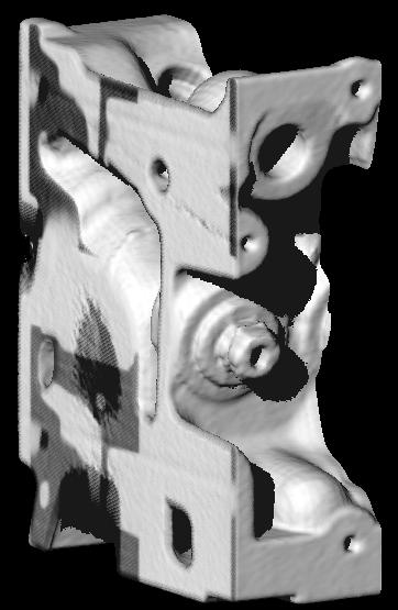
5 as a degenerate 3-dimensional texture, since the initial format of the image is RGB. After this step, the framebuffer contains the absorption factor from Equation 4 for each pixel. Finally, the scene is rendered again, this time with its regular textures and lighting, but blending is set up in such a way, that these colors are blended with the current framebuffer content according to Equation 3. Figure 6: Two examples for Euclidean distance fog. Figure 6 shows images rendered with this method on a SGI Octane MXI. This scene can be rendered at 15 frames/sec. for a resolution. 5.2 Layered Fog Both the traditional hardware fog and the algorithm presented above have in common that the fog is uniform, that is, its density is constant for the whole scene. Layered fog is a concept that softens this restriction, by allowing the density to change as a function of height [13]. This means that a visual simulation application could specify a relatively dense layer of fog on the ground, followed by an area of relatively clear sky, and then a layer of clouds higher up. The algorithm for layered fog that we present in the following is similar to the Euclidean distance fog algorithm presented above. However, instead of a 1-dimensional pixel texture we now have to use a 2-dimensional or 3-dimensional one. The idea of fog computation through table lookups is borrowed from [13], but our method is faster due to the use of pixel textures, which allows us to perform all computations in hardware. Due to the restriction to layers of constant fog density, the exponent from Equation 4 simplifies to Z d σ(t)dt = 0 d yw ye,w Z yw σ(y)dy, (5) ye,w where ye,w is the y-coordinate of the eye point in world space, yw is an object point in world coordinates, and d is the Euclidean distance between the two points as above. This is merely a scaling of the absorption for a vertical ray from an object point at height yw to an eye point at height ye,w (also see Figure 7). yw ye,w yw d ye,w Figure 7: For layered fog, the absorption along an arbitrary ray can be computed directly from the absorption for a vertical ray. An interesting observation is that Equation 5 (and thus Equation 4) is only a a function of 3 variables: ye,w, yw and d. The latter two of these vary per pixel, whereas the first one is a constant within each frame. We propose two slightly different methods for implementing layered fog, both are modifications of the algorithm presented in Section 5.1. The first method R uses a 3-dimensional texture that directly codes d/( yw ye,w ) yyw σ(y)dy e,w e. To compute the three texture coordinates, we read the framebuffer to main memory as in Section 5.1, but this time with a color matrix and lookup tables that store x2e, ye2, ze2 and yw as an RGBα image in main memory. During the writing phase, the color matrix and lookup tables are set up so that they store d and yw in the R and G components. Biasing the blue component by the global constant ye,w yields the third color component, and thus the third texture coordinate for the pixel texture. Since the intermediate format of the image is RGBα, the 3-dimensional fog texture has to be stored as a degenerate 4-dimensional pixel texture. Instead of the biasing step, it is also possible to only use d and yw to effectively reference a 2-dimensional texture, which then has to change every time the eye point moves vertically. This has the advantage that smaller texture RAM sizes are sufficient, but the disadvantage that new textures have to be downloaded to texture RAM if the height of the eye changes. Figure 8 shows images rendered with layered fog, again on a SGI Octane MXI. With both algorithms, this scene can be rendered at 12 frames/sec. for a image resolution. This time is marginally larger than the time for Euclidean distance fog presented above, due to the use of RGBα instead of RGB images. Figure 8: Two examples for layered fog with a dense layer of ground fog and a layer of clouds on the top. Both Euclidean distance and layered fog are most useful in visual simulation applications where realism is a top requirement. They allow for a more accurate simulation of visibility in certain situations. The standard hardware fog which improves the vision in peripheral regions is not adequate in these situations. The methods presented here allow for an efficient, hardware based implementation of both layered and Euclidean distance fog. 6 Environment Mapping Mapped Surfaces for Normal- As a final example for applications of pixel textures, we discuss an algorithm for applying spherical environment maps [8] to surfaces with normal maps. Instead of the spherical parameterization we describe here, it is also possible to use view-independent parabolic maps [11, 10]. We use the term normal map for textures containing color coded normals for each pixel in object space. Normal maps have the advantage that the expensive operations (computing the local surface normal by transforming the bump into the local coordinate frame) have already been performed in a preprocessing stage. All that remains to be done is to use the precomputed normals for lighting each pixel. As we will show in the following, this allows us to
6 use a fairly standard rendering pipeline, which does not explicitly support bump mapping. Another advantage of normal maps is that recently methods have shown up for measuring them directly [20], or for generating them as a by-product of mesh simplification [4]. The parameterization used most commonly in computer graphics hardware today, is the spherical parameterization for environment maps [8]. It is based on the simple analogy of a small, perfectly mirroring ball centered around the object. The image that an orthographic camera sees when looking at this ball from a certain viewing direction is the environment map. With this parameterization, the reflection of a mirroring object can be looked up using the following calculations (see Figure 9 for the geometry). For each vertex compute the reflection vector r of the per-vertex viewing direction v. A spherical environment map which has been generated for an orthographic camera pointing into direction v 0, stores the corresponding radiance information for this direction at the point where the reflective sphere has the normal h := (v 0 + r)/ v 0 + r. If v 0 is the negative z-axis in viewing coordinates, then the 2D texture coordinates are simply the x and y components of the normalized halfway vector h. For environment mapping on a per-vertex basis, these texture coordinates are automatically computed by the texture coordinate generation mechanism of OpenGL. n h r Figure 10: Examples for normal-mapped surfaces with applied environment maps. In the top row, only the mirror components are shown. For the bottom row, Phong lighting has been added with techniques described in [10]. v 0 v Figure 9: The lookup process in a spherical environment map. An interesting observation is that for orthographic cameras, the viewing direction v is identical to the reference viewing direction v 0 for all vertices, and thus, the halfway vector h is identical to the surface normal n. This approximation does not work well for smooth, planar objects, as it causes these objects to receive a single, solid color. However, the approximation can be used for bumpmapping algorithms, since these typically introduce a lot of highfrequency detail, so that the artifacts are rarely noticeable. This means, that the information from a normal map can be directly used to look up a mirror reflection term in a spherical environment map. The algorithm to do this uses pixel textures, and works as follows: First, the object is rendered with the normal map as a texture, and all rendered pixels are marked in the stencil buffer. The resulting image is read back to main memory. During this operation, a color matrix can be used to map the normals from object space into eye space, where the environment map is specified. This yields an image containing eye space normals for each visible pixel. A second rendering pass, in which the 2-dimensional environment map is applied as a degenerate 3-dimensional texture, is then employed to look up the mirror reflection for each pixel (only pixels previously marked in the stencil buffer are considered). Figure 10 shows some images that have been generated with this technique. In addition to the mirror term, it is also possible to add local Phong illumination using additional rendering passes. These algorithms require operations from the imaging subset but no pixel textures, and are therefore not described here. They are discussed in detail in [10]. Spherical environment maps are widely used in interactive computer graphics, but they have the disadvantage that they need to be regenerated for every new viewing position and -direction. In [11], a different, parabolic parameterization has been introduced, which does not have this disadvantage. Since this parameterization also uses the halfway vector h for the environment lookup, the same technique can be applied to these maps. A combination of parabolic environment maps and pixel textures with support for projective texturing allows one to apply one environment map to a normal mapped surface for all viewing positions and -directions (a detailed discussion of this topic can be found in [10]. Without projective texturing, parabolic environment maps can, like spherical maps, only be used for one viewing direction. The techniques discussed in this section provide efficient ways for applying environment maps to normal mapped surfaces. Combined with techniques for local illumination, described in [11], this allows for the efficient implementation of normal mapped surfaces. 7 Discussion In this paper we have used the SGI pixel texture extension in a number of algorithms for a variety of different applications: hardwarebased line-integral convolution, shadow mapping, complex fog models and environment mapping for normal mapped surfaces. These algorithms provide efficient, high quality implementations for problems in visualization and realistic image synthesis. In addition to being valuable contributions on their own, they also demonstrate some techniques for using pixel textures and the new OpenGL imaging subset. In the following, we will discuss some observations we have made while working on these algorithms.
7 Firstly, the OpenGL imaging subset is also useful for many applications outside traditional image processing. Especially when combined with pixel textures, the color matrix is a powerful way for transforming points and vectors between different coordinate systems. Lookup tables and scaling/biasing additionally allow for non-linear operations such as the computation of a Euclidean distance. Secondly, we should mention the major limitation of pixel textures in the presented scenarios. The most crucial drawback stems from the limited depth of the available frame buffers. When data is stored in a pixel texture and rendered into the framebuffer usually precision is lost. For example, if the shadow map in which z-values are stored is mapped and drawn into an 8 Bit display, quantization artifacts arise which can be seen particularly at shadow boundaries. The same holds for the simulation of realistic fog models where the exponential attenuation is quantized into a limited number of bins. Furthermore, the frame buffer depth strongly determines the size of textures that can be accessed. Effectively, only textures up to 256x256 can be mapped using 8 Bit displays. In our applications we therefore used the deeper visuals provided by the Octane graphics system. With 12 bits per component, these quantization artifacts are already softened significantly. Nonetheless for some applications such as shadow maps, even deeper visuals would be beneficial. As a consequence, we see specifically designed visuals or additional buffers with limited functionality but higher precision as one of the dominant features in future generation graphics hardware. As a final observation, we found that the flexibility of the pixel texture extension could be further improved through two minor changes in the specification. One change regards the support of projective textures. By introducing a mode that performs a perspective division by the q component, this important feature could be supported. This would, for example, open the door for a general shadow map algorithm as shown in Section 4 and view-independent environment maps (Section 6), but other applications are also possible. Of course it could be argued that a perspective divide for every pixel is an expensive operation, but on the other hand there are applications, such as shadow mapping, where this operation has to be performed at some point. It is then better to have hardware support for this instead of forcing the user to fall back to software. The second change regards the coupling of image format and dimensionality of the pixel texture. We think that there really is no good reason for this. In many of the methods we have demonstrated how the number of color components can be expanded or reduced through the use of color matrices and lookup tables. Therefore it is reasonable to allow pixel textures with an arbitrary dimension to be used with images of any internal format. While these two changes would certainly help to make the pixel texture extension even more powerful, even the current specification has many applications. The described algorithms only show a small part of these applications of pixel textures, but they demonstrate the potential of the extension is for achieving high quality, high performance renderings. We believe that pixel textures should become a standard component of the graphics pipeline, and that this extension should become part of the OpenGL standard. 8 Acknowledgments We would like to thank Peter-Pike Sloan for a discussion of the shadow map algorithm, and the anonymous reviewers for their valuable comments. References [1] Kurt Akeley. RealityEngine graphics. In Computer Graphics (SIGGRAPH 93 Proceedings), pages , August [2] Brian Cabral, Nancy Cam, and Jim Foran. Accelerated volume rendering and tomographic reconstruction using texture mapping hardware. In 1994 Symposium on Volume Visualization, pages 91 98, October [3] Brian Cabral and Leith Casey Leedom. Imaging vector fields using line integral convolution. In Computer Graphics (SIG- GRAPH 93 Proceedings), pages , August [4] Jonathan Cohen, Marc Olano, and Dinesh Manocha. Appearance-preserving simplification. In Computer Graphics (SIGGRAPH 98 Proceedings), pages , July [5] Robert A. Drebin, Loren Carpenter, and Pat Hanrahan. Volume rendering. In Computer Graphics (SIGGRAPH 88 Proceedings), pages 65 74, August [6] David Ebert, Kent Musgrave, Darwyn Peachey, Ken Perlin, and Worley. Texturing and Modeling: A Procedural Approach. Academic Press, October ISBN [7] Paul Haeberli and Kurt Akeley. The accumulation buffer: Hardware support for high-quality rendering. In Computer Graphics (SIGGRAPH 90 Proceedings), pages , August [8] Paul Haeberli and Mark Segal. Texture mapping as a fundamental drawing primitive. In Fourth Eurographics Workshop on Rendering, pages , June [9] Paul Hansen. Introducing pixel texture. In Developer News, pages Silicon Graphics Inc., May [10] Wolfgang Heidrich. High-Quality Shading and Lighting for Hardware-Accelerated Rendering. PhD thesis, University of Erlangen-Nürnberg, in prepraration. [11] Wolfgang Heidrich and Hans-Peter Seidel. View-independent environment maps. In Eurographics/SIGGRAPH Workshop on Graphics Hardware, pages 39 45, [12] Silicon Graphics Inc. Pixel Texture Extension, December Specification document, available from [13] Justin Legakis. Fast multi-layer fog. In Siggraph 98 Conference Abstracts and Applications, page 266, July Siggraph Technical Sketch. [14] Marc Levoy. Volume rendering using the fourier projectionslice theorem. In Proceedings of Graphics Interface 92, pages 61 69, May [15] Steven Molnar, John Eyles, and John Poulton. PixelFlow: High-speed rendering using image composition. In Computer Graphics (SIGGRAPH 92 Proceedings), pages , July [16] Jackie Neider, Tom Davis, and Mason Woo. OpenGL Programming Guide. Addison Wesley, [17] OpenGL ARB. OpenGL Specification, Version 1.2, 1998.
8 [18] Mark Peercy, John Airey, and Brian Cabral. Efficient bump mapping hardware. In Computer Graphics (SIGGRAPH 97 Proceedings), pages , August [19] Ken Perlin and Eric M. Hoffert. Hypertexture. In Computer Graphics (SIGGRAPH 89 Proceedings), pages , July [20] Holly Rushmeier, Gabriel Taubin, and André Guéziec. Applying shape from lighting variation to bump map capture. In Rendering Techniques 97 (Proceedings of Eurographics Rendering Workshop), pages 35 44, June [21] Mark Segal, Carl Korobkin, Rolf van Widenfelt, Jim Foran, and Paul Haeberli. Fast shadow and lighting effects using texture mapping. In Computer Graphics (SIGGRAPH 92 Proceedings), pages , July [22] Detlev Stalling and Hans-Christian Hege. Fast and resolution independent line integral convolution. In SIGGRAPH 95 Conference Proceedings, pages , August [23] Rüdiger Westermann and Thomas Ertl. Efficiently using graphics hardware in volume rendering applications. In Computer Graphics (SIGGRAPH 98 Proceedings), pages , July [24] Lance Williams. Casting curved shadows on curved surfaces. In Computer Graphics (SIGGRAPH 78 Proceedings), pages , August 1978.

9
Light Field Techniques for Reflections and Refractions
 Light Field Techniques for Reflections and Refractions Wolfgang Heidrich, Hendrik Lensch, Michael F. Cohen, Hans-Peter Seidel Max-Planck-Institute for Computer Science {heidrich,lensch,seidel}@mpi-sb.mpg.de
Practical Shadow Mapping
 Practical Shadow Mapping Stefan Brabec Thomas Annen Hans-Peter Seidel Max-Planck-Institut für Informatik Saarbrücken, Germany Abstract In this paper we propose several methods that can greatly improve
Shadow Mapping for Hemispherical and Omnidirectional Light Sources
 Shadow Mapping for Hemispherical and Omnidirectional Light Sources Abstract Stefan Brabec Thomas Annen Hans-Peter Seidel Computer Graphics Group Max-Planck-Institut für Infomatik Stuhlsatzenhausweg 85,
Interactive Rendering of Globally Illuminated Glossy Scenes
 Interactive Rendering of Globally Illuminated Glossy Scenes Wolfgang Stürzlinger, Rui Bastos Dept. of Computer Science, University of North Carolina at Chapel Hill {stuerzl bastos}@cs.unc.edu Abstract.
Advanced Shading and Texturing
 Real-Time Graphics Architecture Kurt Akeley Pat Hanrahan http://www.graphics.stanford.edu/courses/cs448a-01-fall Advanced Shading and Texturing 1 Topics Features Bump mapping Environment mapping Shadow
Shadow Volumes Revisited
 Shadow Volumes Revisited Stefan Roettger, Alexander Irion, and Thomas Ertl University of Stuttgart, Faculty of Computer Science Visualization and Interactive Systems Group! ABSTRACT We present a method
Chapter 1 Introduction. Marc Olano
 Chapter 1 Introduction Marc Olano 1 About This Course Or, why do we want to do real-time shading, and why offer a course on it? Over the years of graphics hardware development, there have been obvious
A Warping-based Refinement of Lumigraphs
 A Warping-based Refinement of Lumigraphs Wolfgang Heidrich, Hartmut Schirmacher, Hendrik Kück, Hans-Peter Seidel Computer Graphics Group University of Erlangen heidrich,schirmacher,hkkueck,seidel@immd9.informatik.uni-erlangen.de
CHAPTER 1 Graphics Systems and Models 3
 ?????? 1 CHAPTER 1 Graphics Systems and Models 3 1.1 Applications of Computer Graphics 4 1.1.1 Display of Information............. 4 1.1.2 Design.................... 5 1.1.3 Simulation and Animation...........
Deferred Rendering Due: Wednesday November 15 at 10pm
 CMSC 23700 Autumn 2017 Introduction to Computer Graphics Project 4 November 2, 2017 Deferred Rendering Due: Wednesday November 15 at 10pm 1 Summary This assignment uses the same application architecture
Towards Interactive Bump Mapping with Anisotropic Shift-Variant BRDFs
 Towards Interactive Bump Mapping with Anisotropic Shift-Variant BRDFs Jan Kautz Hans-Peter Seidel Max-Planck-Institute for Computer Science Abstract In this paper a technique is presented that combines
CMSC427 Advanced shading getting global illumination by local methods. Credit: slides Prof. Zwicker
 CMSC427 Advanced shading getting global illumination by local methods Credit: slides Prof. Zwicker Topics Shadows Environment maps Reflection mapping Irradiance environment maps Ambient occlusion Reflection
Soft Shadow Maps for Linear Lights
 Soft Shadow Maps for Linear Lights Wolfgang Heidrich Stefan Brabec Hans-Peter Seidel Max-Planck-Institute for Computer Science Im Stadtwald 66123 Saarbrücken Germany heidrich,brabec,hpseidel @mpi-sb.mpg.de
Computer Graphics Shadow Algorithms
 Computer Graphics Shadow Algorithms Computer Graphics Computer Science Department University of Freiburg WS 11 Outline introduction projection shadows shadow maps shadow volumes conclusion Motivation shadows
Applications of Explicit Early-Z Culling
 Applications of Explicit Early-Z Culling Jason L. Mitchell ATI Research Pedro V. Sander ATI Research Introduction In past years, in the SIGGRAPH Real-Time Shading course, we have covered the details of
First Steps in Hardware Two-Level Volume Rendering
 First Steps in Hardware Two-Level Volume Rendering Markus Hadwiger, Helwig Hauser Abstract We describe first steps toward implementing two-level volume rendering (abbreviated as 2lVR) on consumer PC graphics
Visualizer An implicit surface rendering application
 June 01, 2004 Visualizer An implicit surface rendering application Derek Gerstmann - C1405511 MSc Computer Animation NCCA Bournemouth University OVERVIEW OF APPLICATION Visualizer is an interactive application
Rendering Algorithms: Real-time indirect illumination. Spring 2010 Matthias Zwicker
 Rendering Algorithms: Real-time indirect illumination Spring 2010 Matthias Zwicker Today Real-time indirect illumination Ray tracing vs. Rasterization Screen space techniques Visibility & shadows Instant
CS 130 Final. Fall 2015
 CS 130 Final Fall 2015 Name Student ID Signature You may not ask any questions during the test. If you believe that there is something wrong with a question, write down what you think the question is trying
Efficient Rendering of Glossy Reflection Using Graphics Hardware
 Efficient Rendering of Glossy Reflection Using Graphics Hardware Yoshinori Dobashi Yuki Yamada Tsuyoshi Yamamoto Hokkaido University Kita-ku Kita 14, Nishi 9, Sapporo 060-0814, Japan Phone: +81.11.706.6530,
Rasterization Overview
 Rendering Overview The process of generating an image given a virtual camera objects light sources Various techniques rasterization (topic of this course) raytracing (topic of the course Advanced Computer
Hardware Shading: State-of-the-Art and Future Challenges
 Hardware Shading: State-of-the-Art and Future Challenges Hans-Peter Seidel Max-Planck-Institut für Informatik Saarbrücken,, Germany Graphics Hardware Hardware is now fast enough for complex geometry for
Buffers, Textures, Compositing, and Blending. Overview. Buffers. David Carr Virtual Environments, Fundamentals Spring 2005 Based on Slides by E.
 INSTITUTIONEN FÖR SYSTEMTEKNIK LULEÅ TEKNISKA UNIVERSITET Buffers, Textures, Compositing, and Blending David Carr Virtual Environments, Fundamentals Spring 2005 Based on Slides by E. Angel Compositing,
Orthogonal Projection Matrices. Angel and Shreiner: Interactive Computer Graphics 7E Addison-Wesley 2015
 Orthogonal Projection Matrices 1 Objectives Derive the projection matrices used for standard orthogonal projections Introduce oblique projections Introduce projection normalization 2 Normalization Rather
The Terrain Rendering Pipeline. Stefan Roettger, Ingo Frick. VIS Group, University of Stuttgart. Massive Development, Mannheim
 The Terrain Rendering Pipeline Stefan Roettger, Ingo Frick VIS Group, University of Stuttgart wwwvis.informatik.uni-stuttgart.de Massive Development, Mannheim www.massive.de Abstract: From a game developers
CSE528 Computer Graphics: Theory, Algorithms, and Applications
 CSE528 Computer Graphics: Theory, Algorithms, and Applications Hong Qin State University of New York at Stony Brook (Stony Brook University) Stony Brook, New York 11794--4400 Tel: (631)632-8450; Fax: (631)632-8334
Illuminating Micro Geometry Based on Precomputed Visibility
 Illuminating Micro Geometry Based on Precomputed Visibility Wolfgang Heidrich Katja Daubert Jan Kautz Hans-Peter Seidel Max-Planck-Institute for Computer Science Abstract Many researchers have been arguing
Today. Texture mapping in OpenGL. Texture mapping. Basic shaders for texturing. Today. Computergrafik
 Computergrafik Today Basic shader for texture mapping Texture coordinate assignment Antialiasing Fancy textures Matthias Zwicker Universität Bern Herbst 2009 Texture mapping Glue textures (images) onto
Pipeline Operations. CS 4620 Lecture Steve Marschner. Cornell CS4620 Spring 2018 Lecture 11
 Pipeline Operations CS 4620 Lecture 11 1 Pipeline you are here APPLICATION COMMAND STREAM 3D transformations; shading VERTEX PROCESSING TRANSFORMED GEOMETRY conversion of primitives to pixels RASTERIZATION
CS 354R: Computer Game Technology
 CS 354R: Computer Game Technology Texture and Environment Maps Fall 2018 Texture Mapping Problem: colors, normals, etc. are only specified at vertices How do we add detail between vertices without incurring
Pipeline Operations. CS 4620 Lecture 14
 Pipeline Operations CS 4620 Lecture 14 2014 Steve Marschner 1 Pipeline you are here APPLICATION COMMAND STREAM 3D transformations; shading VERTEX PROCESSING TRANSFORMED GEOMETRY conversion of primitives
Introduction to Visualization and Computer Graphics
 Introduction to Visualization and Computer Graphics DH2320, Fall 2015 Prof. Dr. Tino Weinkauf Introduction to Visualization and Computer Graphics Visibility Shading 3D Rendering Geometric Model Color Perspective
The Traditional Graphics Pipeline
 Last Time? The Traditional Graphics Pipeline Participating Media Measuring BRDFs 3D Digitizing & Scattering BSSRDFs Monte Carlo Simulation Dipole Approximation Today Ray Casting / Tracing Advantages? Ray
Computergrafik. Matthias Zwicker. Herbst 2010
 Computergrafik Matthias Zwicker Universität Bern Herbst 2010 Today Bump mapping Shadows Shadow mapping Shadow mapping in OpenGL Bump mapping Surface detail is often the result of small perturbations in
Topics and things to know about them:
 Practice Final CMSC 427 Distributed Tuesday, December 11, 2007 Review Session, Monday, December 17, 5:00pm, 4424 AV Williams Final: 10:30 AM Wednesday, December 19, 2007 General Guidelines: The final will
Lets assume each object has a defined colour. Hence our illumination model is looks unrealistic.
 Shading Models There are two main types of rendering that we cover, polygon rendering ray tracing Polygon rendering is used to apply illumination models to polygons, whereas ray tracing applies to arbitrary
The Traditional Graphics Pipeline
 Last Time? The Traditional Graphics Pipeline Reading for Today A Practical Model for Subsurface Light Transport, Jensen, Marschner, Levoy, & Hanrahan, SIGGRAPH 2001 Participating Media Measuring BRDFs
Shadow Rendering EDA101 Advanced Shading and Rendering
 Shadow Rendering EDA101 Advanced Shading and Rendering 2006 Tomas Akenine-Möller 1 Why, oh why? (1) Shadows provide cues about spatial relationships among objects 2006 Tomas Akenine-Möller 2 Why, oh why?
Real-time Shading: Hardware Shading Effects
 Real-time Shading: Hardware Shading Effects Wolfgang Heidrich The University of British Columbia Abstract In this part of the course we will review some examples of shading algorithms that we might want
Level of Details in Computer Rendering
 Level of Details in Computer Rendering Ariel Shamir Overview 1. Photo realism vs. Non photo realism (NPR) 2. Objects representations 3. Level of details Photo Realism Vs. Non Pixar Demonstrations Sketching,
Computergrafik. Matthias Zwicker Universität Bern Herbst 2016
 Computergrafik Matthias Zwicker Universität Bern Herbst 2016 2 Today Basic shader for texture mapping Texture coordinate assignment Antialiasing Fancy textures 3 Texture mapping Glue textures (images)
Texture Mapping as a Fundamental Drawing Primitive
 Appeared in Proc. Fourth Eurographics Workshop on Rendering, Michael Cohen, Claude Puech, and Francois Sillion, eds. Paris, France, June, 1993. pp. 259-266. Texture Mapping as a Fundamental Drawing Primitive
Computer Graphics. Shadows
 Computer Graphics Lecture 10 Shadows Taku Komura Today Shadows Overview Projective shadows Shadow texture Shadow volume Shadow map Soft shadows Why Shadows? Shadows tell us about the relative locations
Soft shadows. Steve Marschner Cornell University CS 569 Spring 2008, 21 February
 Soft shadows Steve Marschner Cornell University CS 569 Spring 2008, 21 February Soft shadows are what we normally see in the real world. If you are near a bare halogen bulb, a stage spotlight, or other
3D Rasterization II COS 426
 3D Rasterization II COS 426 3D Rendering Pipeline (for direct illumination) 3D Primitives Modeling Transformation Lighting Viewing Transformation Projection Transformation Clipping Viewport Transformation
The Traditional Graphics Pipeline
 Final Projects Proposals due Thursday 4/8 Proposed project summary At least 3 related papers (read & summarized) Description of series of test cases Timeline & initial task assignment The Traditional Graphics
Complex Shading Algorithms
 Complex Shading Algorithms CPSC 414 Overview So far Rendering Pipeline including recent developments Today Shading algorithms based on the Rendering Pipeline Arbitrary reflection models (BRDFs) Bump mapping
Shadows in the graphics pipeline
 Shadows in the graphics pipeline Steve Marschner Cornell University CS 569 Spring 2008, 19 February There are a number of visual cues that help let the viewer know about the 3D relationships between objects
Graphics Hardware and Display Devices
 Graphics Hardware and Display Devices CSE328 Lectures Graphics/Visualization Hardware Many graphics/visualization algorithms can be implemented efficiently and inexpensively in hardware Facilitates interactive
Illumination Under Trees. Nelson Max University of Tokyo, and University of California, Davis
 Illumination Under Trees Nelson Max University of Tokyo, and University of California, Davis Topics Hierarchical image based rendering for trees Atmospheric illumination and shadows Shadow penumbras with
An Efficient Approach for Emphasizing Regions of Interest in Ray-Casting based Volume Rendering
 An Efficient Approach for Emphasizing Regions of Interest in Ray-Casting based Volume Rendering T. Ropinski, F. Steinicke, K. Hinrichs Institut für Informatik, Westfälische Wilhelms-Universität Münster
CS451Real-time Rendering Pipeline
 1 CS451Real-time Rendering Pipeline JYH-MING LIEN DEPARTMENT OF COMPUTER SCIENCE GEORGE MASON UNIVERSITY Based on Tomas Akenine-Möller s lecture note You say that you render a 3D 2 scene, but what does
Textures. Texture coordinates. Introduce one more component to geometry
 Texturing & Blending Prof. Aaron Lanterman (Based on slides by Prof. Hsien-Hsin Sean Lee) School of Electrical and Computer Engineering Georgia Institute of Technology Textures Rendering tiny triangles
Simpler Soft Shadow Mapping Lee Salzman September 20, 2007
 Simpler Soft Shadow Mapping Lee Salzman September 20, 2007 Lightmaps, as do other precomputed lighting methods, provide an efficient and pleasing solution for lighting and shadowing of relatively static
Self-shadowing Bumpmap using 3D Texture Hardware
 Self-shadowing Bumpmap using 3D Texture Hardware Tom Forsyth, Mucky Foot Productions Ltd. TomF@muckyfoot.com Abstract Self-shadowing bumpmaps add realism and depth to scenes and provide important visual
Applications of Explicit Early-Z Z Culling. Jason Mitchell ATI Research
 Applications of Explicit Early-Z Z Culling Jason Mitchell ATI Research Outline Architecture Hardware depth culling Applications Volume Ray Casting Skin Shading Fluid Flow Deferred Shading Early-Z In past
Adaptive Point Cloud Rendering
 1 Adaptive Point Cloud Rendering Project Plan Final Group: May13-11 Christopher Jeffers Eric Jensen Joel Rausch Client: Siemens PLM Software Client Contact: Michael Carter Adviser: Simanta Mitra 4/29/13
Clipping. CSC 7443: Scientific Information Visualization
 Clipping Clipping to See Inside Obscuring critical information contained in a volume data Contour displays show only exterior visible surfaces Isosurfaces can hide other isosurfaces Other displays can
graphics pipeline computer graphics graphics pipeline 2009 fabio pellacini 1
 graphics pipeline computer graphics graphics pipeline 2009 fabio pellacini 1 graphics pipeline sequence of operations to generate an image using object-order processing primitives processed one-at-a-time
Shading Languages. Seminar Computer Graphics. Markus Kummerer
 Shading Languages Markus Kummerer ABSTRACT Shading Languages provide a highly flexible approach for creating visual structures in computer imagery. The RenderMan Interface provides an API for scene description,
Reading. 18. Projections and Z-buffers. Required: Watt, Section , 6.3, 6.6 (esp. intro and subsections 1, 4, and 8 10), Further reading:
, Further reading:") Reading Required: Watt, Section 5.2.2 5.2.4, 6.3, 6.6 (esp. intro and subsections 1, 4, and 8 10), Further reading: 18. Projections and Z-buffers Foley, et al, Chapter 5.6 and Chapter 6 David F. Rogers
Reading Required: Watt, Section 5.2.2 5.2.4, 6.3, 6.6 (esp. intro and subsections 1, 4, and 8 10), Further reading: 18. Projections and Z-buffers Foley, et al, Chapter 5.6 and Chapter 6 David F. Rogers
Computer Graphics I Lecture 11
 15-462 Computer Graphics I Lecture 11 Midterm Review Assignment 3 Movie Midterm Review Midterm Preview February 26, 2002 Frank Pfenning Carnegie Mellon University http://www.cs.cmu.edu/~fp/courses/graphics/
C P S C 314 S H A D E R S, O P E N G L, & J S RENDERING PIPELINE. Mikhail Bessmeltsev
 C P S C 314 S H A D E R S, O P E N G L, & J S RENDERING PIPELINE UGRAD.CS.UBC.C A/~CS314 Mikhail Bessmeltsev 1 WHAT IS RENDERING? Generating image from a 3D scene 2 WHAT IS RENDERING? Generating image
graphics pipeline computer graphics graphics pipeline 2009 fabio pellacini 1
 graphics pipeline computer graphics graphics pipeline 2009 fabio pellacini 1 graphics pipeline sequence of operations to generate an image using object-order processing primitives processed one-at-a-time
E.Order of Operations
 Appendix E E.Order of Operations This book describes all the performed between initial specification of vertices and final writing of fragments into the framebuffer. The chapters of this book are arranged
Robust Stencil Shadow Volumes. CEDEC 2001 Tokyo, Japan
 Robust Stencil Shadow Volumes CEDEC 2001 Tokyo, Japan Mark J. Kilgard Graphics Software Engineer NVIDIA Corporation 2 Games Begin to Embrace Robust Shadows 3 John Carmack s new Doom engine leads the way
3D Programming. 3D Programming Concepts. Outline. 3D Concepts. 3D Concepts -- Coordinate Systems. 3D Concepts Displaying 3D Models
 3D Programming Concepts Outline 3D Concepts Displaying 3D Models 3D Programming CS 4390 3D Computer 1 2 3D Concepts 3D Model is a 3D simulation of an object. Coordinate Systems 3D Models 3D Shapes 3D Concepts
Multi-View Soft Shadows. Louis Bavoil
 Multi-View Soft Shadows Louis Bavoil lbavoil@nvidia.com Document Change History Version Date Responsible Reason for Change 1.0 March 16, 2011 Louis Bavoil Initial release Overview The Multi-View Soft Shadows
CS 4620 Program 3: Pipeline
 CS 4620 Program 3: Pipeline out: Wednesday 14 October 2009 due: Friday 30 October 2009 1 Introduction In this assignment, you will implement several types of shading in a simple software graphics pipeline.
Subtractive Shadows: A Flexible Framework for Shadow Level of Detail
 jgt 2008/3/21 15:26 page 45 #1 Vol. 13, No. 1: 45 56 Subtractive Shadows: A Flexible Framework for Shadow Level of Detail Christopher DeCoro and Szymon Rusinkiewicz Princeton University Abstract. We explore
Graphics and Interaction Rendering pipeline & object modelling
 433-324 Graphics and Interaction Rendering pipeline & object modelling Department of Computer Science and Software Engineering The Lecture outline Introduction to Modelling Polygonal geometry The rendering
Fog and Cloud Effects. Karl Smeltzer Alice Cao John Comstock
 Fog and Cloud Effects Karl Smeltzer Alice Cao John Comstock Goal Explore methods of rendering scenes containing fog or cloud-like effects through a variety of different techniques Atmospheric effects make
Image Base Rendering: An Introduction
 Image Base Rendering: An Introduction Cliff Lindsay CS563 Spring 03, WPI 1. Introduction Up to this point, we have focused on showing 3D objects in the form of polygons. This is not the only approach to
Real Time Rendering. CS 563 Advanced Topics in Computer Graphics. Songxiang Gu Jan, 31, 2005
 Real Time Rendering CS 563 Advanced Topics in Computer Graphics Songxiang Gu Jan, 31, 2005 Introduction Polygon based rendering Phong modeling Texture mapping Opengl, Directx Point based rendering VTK
Texture-Mapping Tricks. How Bad Does it Look? We've Seen this Sort of Thing Before. Sampling Texture Maps
 Texture-Mapping Tricks Filtering Textures Textures and Shading Bump Mapping Solid Textures How Bad Does it Look? Let's take a look at what oversampling looks like: Click and drag the texture to rotate
CSE 167: Introduction to Computer Graphics Lecture #18: More Effects. Jürgen P. Schulze, Ph.D. University of California, San Diego Fall Quarter 2016
 CSE 167: Introduction to Computer Graphics Lecture #18: More Effects Jürgen P. Schulze, Ph.D. University of California, San Diego Fall Quarter 2016 Announcements TA evaluations CAPE Final project blog
TEXTURE MAPPING. DVA338 Computer Graphics Thomas Larsson, Afshin Ameri
 TEXTURE MAPPING DVA338 Computer Graphics Thomas Larsson, Afshin Ameri OVERVIEW Motivation Texture Mapping Coordinate Mapping (2D, 3D) Perspective Correct Interpolation Texture Filtering Mip-mapping Anisotropic
Computer Graphics Introduction. Taku Komura
 Computer Graphics Introduction Taku Komura What s this course all about? We will cover Graphics programming and algorithms Graphics data structures Applied geometry, modeling and rendering Not covering
Volume Graphics Introduction
 High-Quality Volume Graphics on Consumer PC Hardware Volume Graphics Introduction Joe Kniss Gordon Kindlmann Markus Hadwiger Christof Rezk-Salama Rüdiger Westermann Motivation (1) Motivation (2) Scientific
TSBK03 Screen-Space Ambient Occlusion
 TSBK03 Screen-Space Ambient Occlusion Joakim Gebart, Jimmy Liikala December 15, 2013 Contents 1 Abstract 1 2 History 2 2.1 Crysis method..................................... 2 3 Chosen method 2 3.1 Algorithm
Line Drawing. Introduction to Computer Graphics Torsten Möller / Mike Phillips. Machiraju/Zhang/Möller
 Line Drawing Introduction to Computer Graphics Torsten Möller / Mike Phillips Rendering Pipeline Hardware Modelling Transform Visibility Illumination + Shading Perception, Color Interaction Texture/ Realism
Volume Rendering with libmini Stefan Roettger, April 2007
 Volume Rendering with libmini Stefan Roettger, April 2007 www.stereofx.org 1. Introduction For the visualization of volumetric data sets, a variety of algorithms exist which are typically tailored to the
Chapter 1. Introduction Marc Olano
 Chapter 1. Introduction Marc Olano Course Background This is the sixth offering of a graphics hardware-based shading course at SIGGRAPH, and the field has changed and matured enormously in that time span.
Grafica Computazionale: Lezione 30. Grafica Computazionale. Hiding complexity... ;) Introduction to OpenGL. lezione30 Introduction to OpenGL
 Introduction to OpenGL. lezione30 Introduction to OpenGL") Grafica Computazionale: Lezione 30 Grafica Computazionale lezione30 Introduction to OpenGL Informatica e Automazione, "Roma Tre" May 20, 2010 OpenGL Shading Language Introduction to OpenGL OpenGL (Open
Grafica Computazionale: Lezione 30 Grafica Computazionale lezione30 Introduction to OpenGL Informatica e Automazione, "Roma Tre" May 20, 2010 OpenGL Shading Language Introduction to OpenGL OpenGL (Open
Introduction Rasterization Z-buffering Shading. Graphics 2012/2013, 4th quarter. Lecture 09: graphics pipeline (rasterization and shading)
") Lecture 9 Graphics pipeline (rasterization and shading) Graphics pipeline - part 1 (recap) Perspective projection by matrix multiplication: x pixel y pixel z canonical 1 x = M vpm per M cam y z 1 This
Lecture 9 Graphics pipeline (rasterization and shading) Graphics pipeline - part 1 (recap) Perspective projection by matrix multiplication: x pixel y pixel z canonical 1 x = M vpm per M cam y z 1 This
Pipeline Operations. CS 4620 Lecture 10
 Pipeline Operations CS 4620 Lecture 10 2008 Steve Marschner 1 Hidden surface elimination Goal is to figure out which color to make the pixels based on what s in front of what. Hidden surface elimination
GUERRILLA DEVELOP CONFERENCE JULY 07 BRIGHTON
 Deferred Rendering in Killzone 2 Michal Valient Senior Programmer, Guerrilla Talk Outline Forward & Deferred Rendering Overview G-Buffer Layout Shader Creation Deferred Rendering in Detail Rendering Passes
Computing Visibility. Backface Culling for General Visibility. One More Trick with Planes. BSP Trees Ray Casting Depth Buffering Quiz
 Computing Visibility BSP Trees Ray Casting Depth Buffering Quiz Power of Plane Equations We ve gotten a lot of mileage out of one simple equation. Basis for D outcode-clipping Basis for plane-at-a-time
Dual-Paraboloid Shadow Mapping. A paper by Stefan Brabec, Thomas Annen, Hans-Peter Seidel Presented By Patrick Wouterse, Selmar Kok
 A paper by Stefan Brabec, Thomas Annen, Hans-Peter Seidel Presented By Patrick Wouterse, Selmar Kok Introduction and Background An improved perspective shadow mapping technique Less memory and render passes
3D graphics, raster and colors CS312 Fall 2010
 Computer Graphics 3D graphics, raster and colors CS312 Fall 2010 Shift in CG Application Markets 1989-2000 2000 1989 3D Graphics Object description 3D graphics model Visualization 2D projection that simulates
lecture 19 Shadows - ray tracing - shadow mapping - ambient occlusion Interreflections
 lecture 19 Shadows - ray tracing - shadow mapping - ambient occlusion Interreflections In cinema and photography, shadows are important for setting mood and directing attention. Shadows indicate spatial
Fast Texture Based Form Factor Calculations for Radiosity using Graphics Hardware
 Fast Texture Based Form Factor Calculations for Radiosity using Graphics Hardware Kasper Høy Nielsen Niels Jørgen Christensen Informatics and Mathematical Modelling The Technical University of Denmark
PowerVR Hardware. Architecture Overview for Developers
 Public Imagination Technologies PowerVR Hardware Public. This publication contains proprietary information which is subject to change without notice and is supplied 'as is' without warranty of any kind.
Programmable GPUS. Last Time? Reading for Today. Homework 4. Planar Shadows Projective Texture Shadows Shadow Maps Shadow Volumes
 Last Time? Programmable GPUS Planar Shadows Projective Texture Shadows Shadow Maps Shadow Volumes frame buffer depth buffer stencil buffer Stencil Buffer Homework 4 Reading for Create some geometry "Rendering
High-Quality Surface Splatting on Today s GPUs
 High-Quality Surface Splatting on Today s GPUs M. Botsch, A. Hornung, M. Zwicker, L. Kobbelt Presented by Julian Yu-Chung Chen CS594 GPU Programming 2006-03-30 Outline Point Based Rendering Surface splatting
Texture. Detail Representation
 Page 1 Texture Procedural shading and texturing Applied and projected textures Material / light properties Shadow maps Spherical and higher order textures Spherical mappings Environment and irradiance
Interactive Computer Graphics A TOP-DOWN APPROACH WITH SHADER-BASED OPENGL
 International Edition Interactive Computer Graphics A TOP-DOWN APPROACH WITH SHADER-BASED OPENGL Sixth Edition Edward Angel Dave Shreiner Interactive Computer Graphics: A Top-Down Approach with Shader-Based
CS452/552; EE465/505. Clipping & Scan Conversion
 CS452/552; EE465/505 Clipping & Scan Conversion 3-31 15 Outline! From Geometry to Pixels: Overview Clipping (continued) Scan conversion Read: Angel, Chapter 8, 8.1-8.9 Project#1 due: this week Lab4 due:
S U N G - E U I YO O N, K A I S T R E N D E R I N G F R E E LY A VA I L A B L E O N T H E I N T E R N E T
 S U N G - E U I YO O N, K A I S T R E N D E R I N G F R E E LY A VA I L A B L E O N T H E I N T E R N E T Copyright 2018 Sung-eui Yoon, KAIST freely available on the internet http://sglab.kaist.ac.kr/~sungeui/render
Direct Volume Rendering
 Direct Volume Rendering Visualization Torsten Möller Weiskopf/Machiraju/Möller Overview 2D visualization slice images (or multi-planar reformating MPR) Indirect 3D visualization isosurfaces (or surface-shaded