Turbocharger Design & Analysis Solutions. Bill Holmes Brad Hutchinson Detroit, October 2012
|
|
|
- Owen Evans
- 5 years ago
- Views:
Transcription

1 Turbocharger Design & Analysis Solutions Bill Holmes Brad Hutchinson Detroit, October 2012
2 Agenda ANSYS overview ANSYS TurboSystem Blade row solutions The ANSYS Transformation methods An example: turbocharger compressor analysis Summary


3 ANSYS Vision for Rotating Machinery: Full machine simulation High fidelity simulation of all components Simulate complex phenomena and processes Unsteady combustion, compressor stall, cavitation, noise, fracture, component interactions, advanced materials... Integrated tool set for all geometry and physics Large scale High Performance Computing (HPC) enabled
4 ANSYS TurboSystem


5 ANSYS Axial and centrifugal compressors Axial and radial turbines (Steam & gas) Centrifugal, mixed flow and axial pumps Axial and radial fans Automotive turbomachinery Water turbines Wind turbines


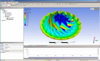
6 ANSYS TurboSystem Complete turbomachinery design and analysis in ANSYS Workbench Geometry Throughflow Meshing CFD Thermal Combustion Structural mechanics Rotordynamics Post processing Optimization This presentation will focus on ANSYS blade row fluid dynamics for turbocharger compressors

7 ANSYS Workbench Parametric Geometry (Meanline & Through-Flow) Mesh Robust Design Analysis
8 ANSYS Workbench
9 ANSYS Workbench

10 ANSYS Workbench

11 ANSYS Workbench

12 ANSYS Workbench

13 ANSYS Workbench

14 ANSYS Workbench
15 ANSYS Workbench
16 ANSYS Workbench

17 ANSYS Workbench
18 BladeModeler Meanline Design Vista CCD Centrifugal compressor rotor design Real gas capability

19 BladeModeler Meanline Design Vista RTD Radial turbine preliminary design

20 ANSYS BladeModeler Design comparison Visible in meridional sketches, angle/thickness views, blade to blade view and 3D view
21 ANSYS TurboGrid Automated grid generation for bladed turbomachinery components High quality hexahedral grids Repeatable Minimize mesh influence in design comparison Scalable Maintain quality with mesh refinement
22 Centrifugal Compressor


23 ANSYS Turbomachinery Fast & scalable solver Low speed to supersonic Steady/transient Turbo specific BC s Turbulence & heat transfer Multiple Frame of Reference Multi phase flow Real fluids Fluid/structure interaction


24 Turbulence Model Detached Eddy Simulation Laminarturbulent transition Streamline curvature & rotation Scale Adaptive Simulation SST Model 'Automatic' wall functions Wall roughness Stagnation line flows EARSM


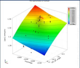
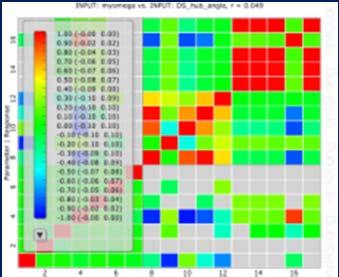
25 ANSYS Design Exploration Sensitivity analysis Design optimization Robustness evaluation initial
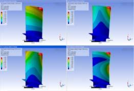
26 Mechanical Mechanical deformation Rotational forces Surface pressure loads Thermal stress Temperature, Heat flux, Modal analysis Frequencies Blade flutter Aerodynamic damping Forced response Transient Rotor Stator Full 2 way FSI
27 ANSYS Transient Blade Row Methods


28 TBR with pitch change: The ANSYS Transformation methods Problem: How to obtain the full wheel transient solution, but at low cost? Solution: The ANSYS TBR Transformation family of methods onew models minimize number of simulated passages, providing enormous efficiency gains and reduced infrastructure requirements


29 Steady with Pitch Change Fast Blade Row Solutions Transient with Pitch Change Transient Full-Domain Time Domain Profile Transformation Time Transformation Status: Release & Beta Fourier Transformation Frequency Domain Harmonic Transformation Status: Development


30 ANSYS TBR Applications Single Stage Multi Stage Gust Analysis Turbine TBR Applications Blade Flutter displacement Period Gust speed Blade Passage pitch 2 IBPA j Nb j 0 Nb 1 Damping Coef. IBPA Gust pitch


31 Turbocharging Unsteady State Rotor Stator Interaction (Off Design) Inlet distortion Acoustics Turbulent flow with conjugate heat transfer Multi physics Forced response Thermal Optimization & Robust Design Map Width Enhancement, mixed flow turbine wheels, volute configuration ETH Zurich

32 Multi Physics Modeling 3D CAD CSM Mesh CFD Mesh Load Transfer Static & Thermal CSM Aerodynamic CFD


33 ANSYS Turbo System Geometry Mesh Analysis CAD Throughflow Robust Design ANSYS Workbench
34 Example Application: Turbocharger Compressor
35 Turbocharger Compressor Analysis: A Best Practice Example Methodology Preliminary Design Geometry & Meshing Impeller only analysis Impeller diffuservolute analysis Post processing and interpretation
36 Methodology Pre CFD Start with geometry that meets design specifications From Vista CCD, CCM, TF and BladeModeler Impeller only analysis The impeller is the heart of the compression system understand it first Overall performance: how good can it be, can it be better? Nature of the flow, strengths and weaknesses What factors affect performance? Predictions? Whole system Impeller diffuser volute analysis Volute only analysis useful? Post processing Quantitative and qualitative
37 Geometry 1 D design developed in VISTA CCD Based on prescribed duty, design constraints Impeller Geometry VISTA CCD, CCM BladeModeler VISTA TF Make adjustments according to package constraints, design rules, approach etc. Meridional path Blade profile/thickness Hub/backface Tip clearance Volute Geometry Spreadsheet based design Mass + angular momentum conservation approach (free vortex) Drives a parameterized DesignModeler geometry
38 Compressor Design Requirements Parameter Value Diameter 48 [mm] Number of Vanes Inlet Temperature 288 [K] Inlet Pressure [kpa] Mass Flow Rate 0.12 [kg/s] Pressure Ratio 2.15 Tip Speed 391 [m/s] High Specific Flow impeller with vaneless diffuser of radius ratio 1.7 Typical for a gasoline engine with capacity of 1.6L. Mid map operating point Shaft Speed 155,733 [rev min^ 1]
39 Initial Sizing Vista CCD used to create a geometry from design requirements
40 Vista CCD: Output Iterate in CCD to achieve acceptable preliminary design
41 Vista CCM: Input Vista CCM used to create a preliminary compressor map
42 Vista CCM: Output Turbocharger compressor is typically operating at off design
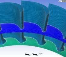
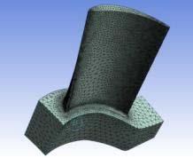
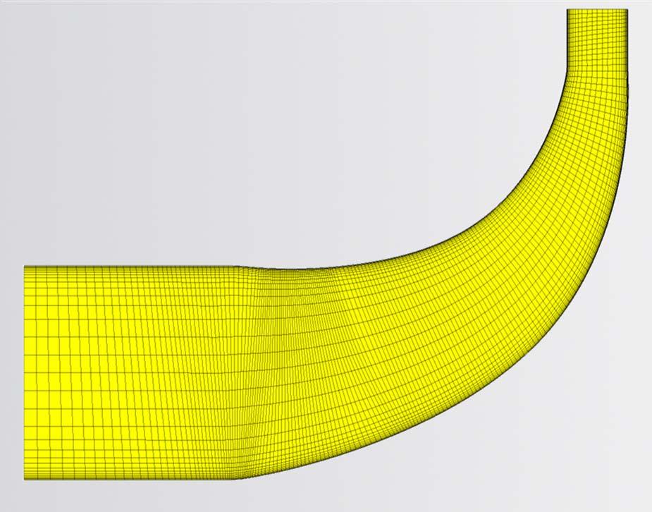
43 Initial Geometry Creation VISTA TF requires a geometry: from BladeModeler Push button solution from Vista CCD Compressor Shroud Section
44 Initial Geometry Creation Compressor Hub Section
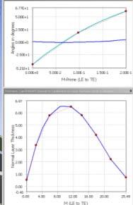
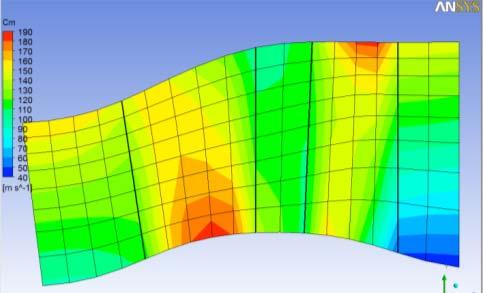
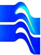
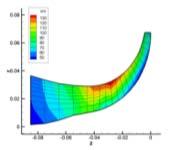
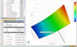
45 Vista TF: 2D Analysis Vista TF is a throughflow (streamline curvature) solver Used to provide further insight into design Contour plots show circumferentially averaged quantities 2D Charts show various design parameters such as loading, incidence and deviation Based on results, geometry can be quickly modified and analyzed again Blade and flowpath design improved Can be parametric and optimization can be performed
46 Vista TF: Qualitative Output Tangential velocity Solution error Meridional velocity Static pressure
47 Vista TF
48 Final Impeller Design Final impeller geometry steps prior to meshing Direct to TurboGrid for hex Create fluid flow path for tet meshing Volute geometry is generated to match impeller Details later
49 Final Geometries Impeller and vaneless diffuser Volute
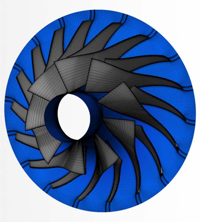
50 Meshing Impeller Mesh Use a hexahedral mesh: TurboGrid ATM Pay attention to: Target mesh size Balance Boundary layer resolution Y+ Tip clearance Aspect ratio Volute mesh ANSYS meshing Tets + prisms for boundary layer resolution Local mesh refinement near tongue Match diffuser outlet/volute inlet spanwise mesh distribution
51 Impeller only Analysis Impeller + part of vaneless diffuser How much of the vaneless space to model? Grid refinement study Grid: The biggest factor affecting predictions Tetrahedral Elements Vs. Hexahedral Elements Understand the effect of grid size on prediction Target: working grid size with Y+=2 Ideally, double/half the grid size in each direction 1/8X, 1X, 8X working grid size Estimate of grid independent solution Effect of fillets Look at key points on the map Nominal design, near surge line, near choke, choke
52 Example: Mesh Independence Study Impeller + Vaneless Diffuser Analyzed at 155, 733 rpm Three operating points Design Flow Rate Near Choke Near Stall/Surge Compared Hex mesh vs. Tet mesh
53 Mesh Summary Hexahedral #of Nodes Blade Y+ Meshing Tool Meshing Method Meshing Time Mesh File Size Max Vol Ratio Max Length Ratio 0.142m 8 TurboGrid ATM 1 min 3.67MB m 4 TurboGrid ATM 1 min 34.8MB m 2 TurboGrid ATM 3 min 273MB Tetrahedral #of Nodes Blade Y+ Meshing Tool Meshing Method Meshing Time Mesh File Size Min Angle Min Quality 0.143m 8 ICEM CFD Octree ~5 min 56.7MB m 4 ICEM CFD Octree ~30 min 601MB m 2 ICEM CFD Octree ~1.5 hr 4.4GB e 06
54 Hex Coarse Mesh
55 Hex Medium Mesh
56 Hex Fine Mesh
57 Tet Coarse Mesh
58 Tet Medium Mesh
59 Tet Fine Mesh
60 Mesh Independence: Hex vs. Tet Total Pressure Tet mesh at approximately 8 million nodes still is not as accurate as Hex mesh at 125 thousand nodes!
61 Mesh Independence: Hex vs. Tet Isentropic Efficiency
62 Mesh Sensitivity: Hex speedline
63 Mesh Sensitivity: Fine Tet speedline added Tet mesh at approximately 8 million nodes still is not as accurate as Hex mesh at 125 thousand nodes!
64 Effect of Fillet 1.5 mm fillet included at main and splitter blade root compared to blade geometry without fillet
65 Fillet Study: Effect on Pressure Ratio Difference only apparent at/near choke
66 Fillet Study: Effect on Isentropic Efficiency Difference only apparent at/near choke
67 Assembly Analysis How much do I really need to model, and using what methods? Impeller diffuser volute? Volute only (including part of vaneless diffuser)? Inlet specified from exit of impeller only analysis Steady state, transient? We did the following, for comparison purposes: Frozen rotor full 360 degrees Stage analysis one impeller with full volute Transient Rotor Stator full 360 degrees Volute only Constant Pt, Tt, flow direction As above but with a spanwise profile
68 Volute Mesh Relatively Coarse Mesh used for Study Size: 370,000 nodes Tet Elements = 1.1 million Prism Elements = 0.32 million Quality Statistics Average Element Quality = 0.71 Min Element Quality = 0.046
69 Effects of Diffuser and Volute Comparison of three different configurations Impeller Only (Single Passage) Impeller + Vaneless Diffuser (Single Passage) Impeller + Vaneless Diffuser + Volute (Full 360, frozen rotor) Compare speedlines 155,733 rpm Pt ratio = (Pt outlet/pt inlet) Isentropic Efficiency
70 Pressure ratio predictions
71 Isentropic efficiency predictions
72 Impeller Behavior Now look at impeller only performance in two configurations Impeller only simulation Impeller diffuser volute simulation Speedlines shows Impeller behaves similarly regardless of downstream geometry Pt ratio = (Pt impeller outlet/pt impeller inlet) Isentropic Efficiency for impeller only Significant value in examining individual components to gain insight
73 Impeller pressure ratio predictions for two configurations
74 Isentropic efficiency predictions for two configurations
75 Effect of rotating stationary frame interface type Comparison of three interface types between diffuser and volute Stage (single passage impeller/diffuser, full volute) Frozen rotor (full 360 degrees) Transient Rotor Stator For all cases Impeller + vaneless diffuser modeled in rotating frame Volute modeled in stationary frame
76 Effect of interface type on total pressure prediction
77 Effect of interface type on isentropic efficiency prediction
78 Post Processing Before starting: Make sure solutions are converged! Run with a big enough time step! Quantitative Impeller Pt, Tt, Abs. flow angle, isentropic efficiency Distortion factor Blade loading Volute: recovery factor, loss coefficient Estimate grid independent solution Qualitative Blade to blade and meridional averaged Unrolled plot at exit of impeller
79 CFD Results Examine results from Compressor Report in CFD Post
80 CFD Results Or use table generation tool in CFD Post to extract custom information at various streamwise locations
81 Blade Loading Chart near choke Mass flow = 0.13 kg/s
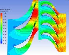
82 Relative Mach Number near choke Mass flow = 0.13 kg/s
83 Relative Velocity near choke Mass flow = 0.13 kg/s
84 Meridional velocity near choke Mass Flow = 0.13 kg/s
85 Static pressure near choke Mass flow = 0.13 kg/s
86 Relative Mach Number near choke Mass flow = 0.13 kg/s


87 Summary ANSYS offers complete turbomachinery design and analysis software Geometry Throughflow Meshing CFD Thermal Combustion Structural mechanics Rotordynamics Post processing Optimization
Advanced Turbomachinery Methods. Brad Hutchinson ANSYS, Inc. Industry Marketing
 Advanced Turbomachinery Methods 1 Brad Hutchinson ANSYS, Inc. Industry Marketing Presentation Overview 1. Turbomachinery challenges 2. ANSYS TurboSystem 3. 2 Blade row fluid dynamics solution methods Available
RAPID DESIGN AND FLOW SIMULATIONS FOR TUBOCHARGER COMPONENTS
 EASC ANSYS Conference 2009 RAPID DESIGN AND FLOW SIMULATIONS FOR TUBOCHARGER COMPONENTS Authors Dipl.-Ing. Jonas Belz Dipl.-Ing. Ralph-Peter Müller CFDnetwork Engineering CFturbo Software & Engineering
Turbomachinery Applications with STAR-CCM+ Turbomachinery Sector Manager
 Turbomachinery Applications with STAR-CCM+ Fred Mendonça Fred Mendonça Turbomachinery Sector Manager An Integrated Solution The applications of the software seem to be infinite. The user-friendly A single
Accurate and Efficient Turbomachinery Simulation. Chad Custer, PhD Turbomachinery Technical Specialist
 Accurate and Efficient Turbomachinery Simulation Chad Custer, PhD Turbomachinery Technical Specialist Outline Turbomachinery simulation advantages Axial fan optimization Description of design objectives
Introduction to ANSYS CFX
 Workshop 03 Fluid flow around the NACA0012 Airfoil 16.0 Release Introduction to ANSYS CFX 2015 ANSYS, Inc. March 13, 2015 1 Release 16.0 Workshop Description: The flow simulated is an external aerodynamics
Advances in Turbomachinery Simulation Fred Mendonça and material prepared by Chad Custer, Turbomachinery Technology Specialist
 Advances in Turbomachinery Simulation Fred Mendonça and material prepared by Chad Custer, Turbomachinery Technology Specialist Usage From Across the Industry Outline Key Application Objectives Conjugate
ANSYS Fluid Structure Interaction for Thermal Management and Aeroelasticity
 ANSYS Fluid Structure Interaction for Thermal Management and Aeroelasticity Phil Stopford Duxford Air Museum 11th May 2011 2011 2010 ANSYS, Inc. All rights reserved. 1 ANSYS, Inc. Proprietary Fluid Structure
CFD ANALYSIS Of COMBINED 8-12 STAGES Of INTERMIDIATE PRESSURE STEAM TURBINE
 CFD ANALYSIS Of COMBINED 8-12 STAGES Of INTERMIDIATE PRESSURE STEAM TURBINE 1st Author name : SHIVAKUMAR VASMATE, 2nd Author name : KAMALADEVI ANANDE. 1 Department of Mechanical Engineering, India 2 Department
Co-Simulation von Flownex und ANSYS CFX am Beispiel einer Verdrängermaschine
 Co-Simulation von Flownex und ANSYS CFX am Beispiel einer Verdrängermaschine Benoit Bosc-Bierne, Dr. Andreas Spille-Kohoff, Farai Hetze CFX Berlin Software GmbH, Berlin Contents Positive displacement compressors
Numerical Simulation of Flow inside a Vaned Diffuser Of a Modified Centrifugal Compressor
 18 th Australasian Fluid Mechanics Conference Launceston, Australia 3-7 December 2012 Numerical Simulation of Flow inside a Vaned Diffuser Of a Modified Centrifugal Compressor Layth H. Jawad, Shahrir Abdullah,
Recent & Upcoming Features in STAR-CCM+ for Aerospace Applications Deryl Snyder, Ph.D.
 Recent & Upcoming Features in STAR-CCM+ for Aerospace Applications Deryl Snyder, Ph.D. Outline Introduction Aerospace Applications Summary New Capabilities for Aerospace Continuity Convergence Accelerator
High-Lift Aerodynamics: STAR-CCM+ Applied to AIAA HiLiftWS1 D. Snyder
 High-Lift Aerodynamics: STAR-CCM+ Applied to AIAA HiLiftWS1 D. Snyder Aerospace Application Areas Aerodynamics Subsonic through Hypersonic Aeroacoustics Store release & weapons bay analysis High lift devices
NUMERICAL INVESTIGATION OF THE FLOW BEHAVIOR INTO THE INLET GUIDE VANE SYSTEM (IGV)
") University of West Bohemia» Department of Power System Engineering NUMERICAL INVESTIGATION OF THE FLOW BEHAVIOR INTO THE INLET GUIDE VANE SYSTEM (IGV) Publication was supported by project: Budování excelentního
University of West Bohemia» Department of Power System Engineering NUMERICAL INVESTIGATION OF THE FLOW BEHAVIOR INTO THE INLET GUIDE VANE SYSTEM (IGV) Publication was supported by project: Budování excelentního
NASA Rotor 67 Validation Studies
 NASA Rotor 67 Validation Studies ADS CFD is used to predict and analyze the performance of the first stage rotor (NASA Rotor 67) of a two stage transonic fan designed and tested at the NASA Glenn center
ANSYS Release 15 Fluids Update
 ANSYS Release 15 Fluids Update 1 Important Note This presentation is an overview of the major improvements in ANSYS Fluid Dynamics at R15.0 This presentation does not include Geometry, Meshing, Systems
Revolve 3D geometry to display a 360-degree image.
 Tutorial 24. Turbo Postprocessing Introduction This tutorial demonstrates the turbomachinery postprocessing capabilities of FLUENT. In this example, you will read the case and data files (without doing
Non Axisymmetric Hub Design Optimization for a High Pressure Compressor Rotor Blade
 Non Axisymmetric Hub Design Optimization for a High Pressure Compressor Rotor Blade Vicky Iliopoulou, Ingrid Lepot, Ash Mahajan, Cenaero Framework Target: Reduction of pollution and noise Means: 1. Advanced
NUMERICAL ANALYSIS OF CENTRIFUGAL PUMP IMPELLER FOR PERFORMANCE IMPROVEMENT
 Int. J. Chem. Sci.: 14(2), 2016, 1148-1156 ISSN 0972-768X www.sadgurupublications.com NUMERICAL ANALYSIS OF CENTRIFUGAL PUMP IMPELLER FOR PERFORMANCE IMPROVEMENT S. KALIAPPAN, M. D. RAJKAMAL and D. BALAMURALI
Axisymmetric Viscous Flow Modeling for Meridional Flow Calculation in Aerodynamic Design of Half-Ducted Blade Rows
 Memoirs of the Faculty of Engineering, Kyushu University, Vol.67, No.4, December 2007 Axisymmetric Viscous Flow Modeling for Meridional Flow alculation in Aerodynamic Design of Half-Ducted Blade Rows by
HYDRAULIC DEVELOPMENT OF A CENTRIFUGAL PUMP IMPELLER USING THE AGILE TURBOMACHINERY DESIGN SYSTEM
 HYDRAULIC DEVELOPMENT OF A CENTRIFUGAL PUMP IMPELLER USING THE AGILE TURBOMACHINERY DESIGN SYSTEM Krzysztof Denus CTD Technology ñ Ing. Buro Denus Colin Osborne Concepts NREC 1. INTRODUCTION The impeller
Speed and Accuracy of CFD: Achieving Both Successfully ANSYS UK S.A.Silvester
 Speed and Accuracy of CFD: Achieving Both Successfully ANSYS UK S.A.Silvester 2010 ANSYS, Inc. All rights reserved. 1 ANSYS, Inc. Proprietary Content ANSYS CFD Introduction ANSYS, the company Simulation
Webinar: TwinMesh for Reliable CFD Analysis of Rotating Positive Displacement Machines
 Webinar: TwinMesh for Reliable CFD Analysis of Rotating Positive Displacement Machines 14.07.2015 Dipl.-Ing. Jan Hesse Jan.hesse@cfx-berlin.de CFX Berlin Software GmbH Karl-Marx-Allee 90 A 10243 Berlin
Reliability - Based Robust Design Optimization of Centrifugal Pump Impeller for Performance Improvement considering Uncertainties in Design Variable
 Reliability - Based Robust Design Optimization of Centrifugal Pump Impeller for Performance Improvement considering Uncertainties in Design Variable M.Balamurugan Assistant Professor, Government College
Parameter based 3D Optimization of the TU Berlin TurboLab Stator with ANSYS optislang
 presented at the 14th Weimar Optimization and Stochastic Days 2017 Source: www.dynardo.de/en/library Parameter based 3D Optimization of the TU Berlin TurboLab Stator with ANSYS optislang Benedikt Flurl
Aerodynamic Design Optimization of Centrifugal Compressor Impeller Based on Genetic Algorithm and Artificial Neural Network
 Aerodynamic Design Optimization of Centrifugal Compressor Impeller Based on Genetic Algorithm and Artificial Neural Network 77 SEIICHI IBARAKI *1 ISAO TOMITA *2 KOICHI SUGIMOTO *2 The centrifugal compressor
Coupled Analysis of FSI
 Coupled Analysis of FSI Qin Yin Fan Oct. 11, 2008 Important Key Words Fluid Structure Interface = FSI Computational Fluid Dynamics = CFD Pressure Displacement Analysis = PDA Thermal Stress Analysis = TSA
Introduction to C omputational F luid Dynamics. D. Murrin
 Introduction to C omputational F luid Dynamics D. Murrin Computational fluid dynamics (CFD) is the science of predicting fluid flow, heat transfer, mass transfer, chemical reactions, and related phenomena
Optimization of an Axial Pump using CFturbo, PumpLinx & optislang
 13th Annual Weimar Optimization and Stochastic Days 2016 Conference for CAE-based parametric optimization, stochastic analysis and Robust Design Optimization Optimization of an Axial Pump using CFturbo,
CFD Modeling of a Radiator Axial Fan for Air Flow Distribution
 CFD Modeling of a Radiator Axial Fan for Air Flow Distribution S. Jain, and Y. Deshpande Abstract The fluid mechanics principle is used extensively in designing axial flow fans and their associated equipment.
NUMERICAL SIMULATION OF FLOW FIELD IN AN ANNULAR TURBINE STATOR WITH FILM COOLING
 24 TH INTERNATIONAL CONGRESS OF THE AERONAUTICAL SCIENCES NUMERICAL SIMULATION OF FLOW FIELD IN AN ANNULAR TURBINE STATOR WITH FILM COOLING Jun Zeng *, Bin Wang *, Yong Kang ** * China Gas Turbine Establishment,
Enhancement of a large injection system for steam turbines
 GE Oil & Gas Leonardo Nettis, GE Oil & Gas Enzo Imparato, GE Oil & Gas Lorenzo Cosi, GE Oil & Gas DOWNSTREAM TECHNOLOGY SOLUTIONS PRODUCTS & SERVICES Enhancement of a large injection system for steam turbines
Proceedings of the ASME 2011 International Mechanical Engineering Congress & Exposition IMECE2011 November 11-17, 2011, Denver, Colorado, USA
 Proceedings of the ASME 2011 International Mechanical Engineering Congress & Exposition IMECE2011 November 11-17, 2011, Denver, Colorado, USA IMECE2011-65058 THE EFFECT OF BLADE LEAN, TWIST AND BOW ON
34% 41% 25% Europe America Asia. Grants 11% Training 1% R&D Industrial Funded Projects 4% Consulting 11% License & Maintenance 73%
 NUMECA as a Company Pioneer Software Developper in the area of Computational Fluid Dynamics (CFD) 15 years market presence with worldwide customer base A team of 60 highly qualified engineers and PhD worldwide
Advanced Computation in the design and development of aircraft engines. Serge Eury SNECMA
 Advanced Computation in the design and development of aircraft engines 1 Serge Eury SNECMA Advanced Computation in the design and development of aircraft engines Introduction Some examples Conclusions
ANSYS AIM 16.0 Overview. AIM Program Management
 1 2015 ANSYS, Inc. September 27, 2015 ANSYS AIM 16.0 Overview AIM Program Management 2 2015 ANSYS, Inc. September 27, 2015 Today s Simulation Challenges Leveraging simulation across engineering organizations
McNair Scholars Research Journal
 McNair Scholars Research Journal Volume 2 Article 1 2015 Benchmarking of Computational Models against Experimental Data for Velocity Profile Effects on CFD Analysis of Adiabatic Film-Cooling Effectiveness
ESTABLISHMENT OF AN OPEN 3D STEAM TURBINE FLUTTER TEST CASE
 Paper ID: ETC2017-315 Proceedings of 12th European Conference on Turbomachinery Fluid dynamics & Thermodynamics ETC12, April 3-7, 2017; Stockholm, Sw eden ESTABLISHMENT OF AN OPEN 3D STEAM TURBINE FLUTTER
Conceptual design tool for radial turbines
 Conceptual design tool for radial turbines Master s Thesis in Applied Mechanics Elias Mikael Vagn Siggeirsson Steinn Gunnarsson Department of Applied Mechanics Chalmers University of Technology Gothenburg,
Using Multiple Rotating Reference Frames
 Tutorial 10. Using Multiple Rotating Reference Frames Introduction Many engineering problems involve rotating flow domains. One example is the centrifugal blower unit that is typically used in automotive
CFD Simulation of a dry Scroll Vacuum Pump including Leakage Flows
 CFD Simulation of a dry Scroll Vacuum Pump including Leakage Flows Jan Hesse, Rainer Andres CFX Berlin Software GmbH, Berlin, Germany 1 Introduction Numerical simulation results of a dry scroll vacuum
DYNARDO Dynardo GmbH CFD Examples. Dr.-Ing. Johannes Will President Dynardo GmbH
 CFD Examples Dr.-Ing. Johannes Will President Dynardo GmbH 1 Flow Simulation of LCD Manufacturing Process Task: - Optimization the flow conditions at a LCD manufacturing process - Inputs: - lab geometry
COMPARISON OF DIFFERENT NUMERICAL APPROACHES AT THE CENTRIFUGAL COMPRESSOR RADIVER
 ISABE-011-14 COMPARISON OF DIFFERENT NUMERICAL APPROACHES AT THE CENTRIFUGAL COMPRESSOR RADIVER Oliver Borm, Balint Balassa, Hans-Peter Kau Institute for Flight Propulsion, Technische Universität München,
Using Multiple Rotating Reference Frames
 Tutorial 9. Using Multiple Rotating Reference Frames Introduction Many engineering problems involve rotating flow domains. One example is the centrifugal blower unit that is typically used in automotive
Simulation and Optimization in the wind energy industry
 Simulation and Optimization in the wind energy industry Numerical Simulation & Optimization www.ozeninc.com/optimization optimization@ozeninc.com Summary Why to use numerical simulations and optimization?
DESIGN OPTIMIZATION OF AN AXIAL FLOW COMPRESSOR FOR INDUSTRIAL GAS TURBINE
 DESIGN OPTIMIZATION OF AN AXIAL FLOW COMPRESSOR FOR INDUSTRIAL GAS TURBINE Nilesh P. Salunke 1, S. A. Channiwala 2, Juned A. R. A 3 1 Research Scholar, SVNIT, Surat, Gujarat, India 2 Professor, Department
NUMERICAL SIMULATION AND THEORETICAL ANALYSIS OF THE 3D VISCOUS FLOW IN CENTRIFUGAL IMPELLERS
 TASK QUARTERLY 5 No 4 (2001), 433 458 NUMERICAL SIMULATION AND THEORETICAL ANALYSIS OF THE 3D VISCOUS FLOW IN CENTRIFUGAL IMPELLERS SHUN KANG AND CHARLES HIRSCH Vrije Universiteit Brussels, Department
Robust Design Optimization and Operating Maps for Computational Fluid Dynamics
 Robust Design Optimization and Operating Maps for Computational Fluid Dynamics Dr. R. Niemeier, Dr.-Ing. S. Kunath, Dr.-Ing. habil. T. Most, Dr.-Ing. J. Will (Dynardo GmbH, Germany); Dr.-Ing. J. Einzinger
Usage of CFX for Aeronautical Simulations
 Usage of CFX for Aeronautical Simulations Florian Menter Development Manager Scientific Coordination ANSYS Germany GmbH Overview Elements of CFD Technology for aeronautical simulations: Grid generation
Effects of bell mouth geometries on the flow rate of centrifugal blowers
 Journal of Mechanical Science and Technology 25 (9) (2011) 2267~2276 www.springerlink.com/content/1738-494x DOI 10.1007/s12206-011-0609-3 Effects of bell mouth geometries on the flow rate of centrifugal
Coupling STAR-CCM+ with Optimization Software IOSO by the example of axial 8-stages jet engine compressor.
 Coupling STAR-CCM+ with Optimization Software IOSO by the example of axial 8-stages jet engine compressor. Folomeev V., (Sarov Engineering Center) Iakunin A., (JSC Klimov) 1 Objectives To create the procedure
S-ducts and Nozzles: STAR-CCM+ at the Propulsion Aerodynamics Workshop. Peter Burns, CD-adapco
 S-ducts and Nozzles: STAR-CCM+ at the Propulsion Aerodynamics Workshop Peter Burns, CD-adapco Background The Propulsion Aerodynamics Workshop (PAW) has been held twice PAW01: 2012 at the 48 th AIAA JPC
Turbulence Modeling. Gilles Eggenspieler, Ph.D. Senior Product Manager
 Turbulence Modeling Gilles Eggenspieler, Ph.D. Senior Product Manager 1 Overview The Role of Steady State (RANS) Turbulence Modeling Overview of Reynolds-Averaged Navier Stokes (RANS) Modeling Capabilities
Parametric design of a Francis turbine runner by means of a three-dimensional inverse design method
 IOP Conference Series: Earth and Environmental Science Parametric design of a Francis turbine runner by means of a three-dimensional inverse design method To cite this article: K Daneshkah and M Zangeneh
CFD SIMULATIONS OF HORIZONTAL AXIS WIND TURBINE (HAWT) BLADES FOR VARIATION WITH WIND SPEED
 BLADES FOR VARIATION WITH WIND SPEED") 2 nd National Conference on CFD Applications in Power and Industry Sectors January 28-29, 2009, Hydrabad, India CFD SIMULATIONS OF HORIZONTAL AXIS WIND TURBINE (HAWT) BLADES FOR VARIATION WITH WIND SPEED
2 nd National Conference on CFD Applications in Power and Industry Sectors January 28-29, 2009, Hydrabad, India CFD SIMULATIONS OF HORIZONTAL AXIS WIND TURBINE (HAWT) BLADES FOR VARIATION WITH WIND SPEED
Numerische Untersuchungen von Windkraftanlagen: Leistung, Wake und Steuerungsstrategien
 Fachtagung Lasermethoden in der Strömungsmesstechnik 8. 10. September 2015, Dresden Numerische Untersuchungen von Windkraftanlagen: Leistung, Wake und Steuerungsstrategien Numerical Investigations of Wind
FE Analysis Of Runner Blade For Small Bulb Turbine
 IOSR Journal of Mechanical and Civil Engineering (IOSR-JMCE) e-issn: 2278-1684,p-ISSN: 2320-334X, Volume 11, Issue 2 Ver.VI I (Mar- Apr. 2014), PP 73-77 FE Analysis Of Runner Blade For Small Bulb Turbine
INTEGRATED CONCEPTUAL DESIGN ENVIRONMENT FOR CENTRIFUGAL COMPRESSORS FLOW PATH DESIGN
 Proceedings of IMECE2008 2008 ASME International Mechanical Engineering Congress and Exposition October 31-November 6, 2008, Boston, Massachusetts, USA IMECE2008-69122 INTEGRATED CONCEPTUAL DESIGN ENVIRONMENT
CD-adapco STAR Global Conference, Orlando, 2013, March 18-20
 Transient Radial Blower Simulation as Part of the Development Process W. Kühnel, M. Weinmann, G. Apostolopoulos, S. Larpent Behr GmbH & Co. KG, Germany CD-adapco STAR Global Conference, Orlando, 2013,
Transition Flow and Aeroacoustic Analysis of NACA0018 Satish Kumar B, Fred Mendonç a, Ghuiyeon Kim, Hogeon Kim
 Transition Flow and Aeroacoustic Analysis of NACA0018 Satish Kumar B, Fred Mendonç a, Ghuiyeon Kim, Hogeon Kim Transition Flow and Aeroacoustic Analysis of NACA0018 Satish Kumar B, Fred Mendonç a, Ghuiyeon
Detached-Eddy Simulation of a Linear Compressor Cascade with Tip Gap and Moving Wall *)
") FOI, Stockholm, Sweden 14-15 July, 2005 Detached-Eddy Simulation of a Linear Compressor Cascade with Tip Gap and Moving Wall *) A. Garbaruk,, M. Shur, M. Strelets, and A. Travin *) Study is carried out
FOI, Stockholm, Sweden 14-15 July, 2005 Detached-Eddy Simulation of a Linear Compressor Cascade with Tip Gap and Moving Wall *) A. Garbaruk,, M. Shur, M. Strelets, and A. Travin *) Study is carried out
CFD Simulation of a Dry Scroll Vacuum Pump Including Leakage Flows
 Purdue University Purdue e-pubs International Compressor Engineering Conference School of Mechanical Engineering 2016 CFD Simulation of a Dry Scroll Vacuum Pump Including Leakage Flows Jan Hesse CFX Berlin
COMPRESSOR CONCEPTUAL DESIGN OPTIMIZATION
 COMPRESSOR CONCEPTUAL DESIGN OPTIMIZATION A Thesis Presented to The Academic Faculty By ANDREW SCOTT MILLER In Partial Fulfillment Of the Requirements for the Degree Master of Science in Aerospace Engineering
Missile External Aerodynamics Using Star-CCM+ Star European Conference 03/22-23/2011
 Missile External Aerodynamics Using Star-CCM+ Star European Conference 03/22-23/2011 StarCCM_StarEurope_2011 4/6/11 1 Overview 2 Role of CFD in Aerodynamic Analyses Classical aerodynamics / Semi-Empirical
CFD Post-Processing of Rampressor Rotor Compressor
 Gas Turbine Industrial Fellowship Program 2006 CFD Post-Processing of Rampressor Rotor Compressor Curtis Memory, Brigham Young niversity Ramgen Power Systems Mentor: Rob Steele I. Introduction Recent movements
DEVELOPMENT OF A METHODOLOGY TO ESTIMATE AERO-PERFORMANCE AND AERO- OPERABILITY LIMITS OF A MULTISTAGE AXIAL FLOW COMPRESSOR FOR USE IN
 DEVELOPMENT OF A METHODOLOGY TO ESTIMATE AERO-PERFORMANCE AND AERO- OPERABILITY LIMITS OF A MULTISTAGE AXIAL FLOW COMPRESSOR FOR USE IN PRELIMINARY DESIGN by SAMEER KULKARNI Submitted in partial fulfillment
Numerical Study of Flow in a Centrifugal Blower
 Numerical Study of Flow in a Centrifugal Blower 1 ISHAN VARMA, 2 RANJITH MANIYERI Department of Mechanical Engineering Symbiosis Institute of Technology (SIT) Symbiosis International University (SIU) Lavale,
Fluid Flow Investigation through Small Turbodrill for Optimal Performance
 Mechanical Engineering Research; Vol. 3, No. 1; 013 ISSN 197-0607 E-ISSN 197-0615 Published by Canadian Center of Science and Education Fluid Flow Investigation through Small Turbodrill for Optimal Performance
THE INFLUENCE OF ROTATING DOMAIN SIZE IN A ROTATING FRAME OF REFERENCE APPROACH FOR SIMULATION OF ROTATING IMPELLER IN A MIXING VESSEL
 Journal of Engineering Science and Technology Vol. 2, No. 2 (2007) 126-138 School of Engineering, Taylor s University College THE INFLUENCE OF ROTATING DOMAIN SIZE IN A ROTATING FRAME OF REFERENCE APPROACH
2008 International ANSYS Conference Strongly Coupled FSI Simulation Moving Compressible Pressure Pulse through a Tube
 2008 International ANSYS Conference Strongly Coupled FSI Simulation Moving Compressible Pressure Pulse through a Tube Daniel L. Cler, US Army RDECOM/ ARDEC/ WSEC/ Benet Labs 1 Overview Background Problem
Automotive Fluid-Structure Interaction (FSI) Concepts, Solutions and Applications. Laz Foley, ANSYS Inc.
 Concepts, Solutions and Applications. Laz Foley, ANSYS Inc.") Automotive Fluid-Structure Interaction (FSI) Concepts, Solutions and Applications Laz Foley, ANSYS Inc. Outline FSI Classifications FSI Solutions FSI Modeling Approaches ANSYS Workbench for FSI System
Automotive Fluid-Structure Interaction (FSI) Concepts, Solutions and Applications Laz Foley, ANSYS Inc. Outline FSI Classifications FSI Solutions FSI Modeling Approaches ANSYS Workbench for FSI System
PARAMETRIC STUDY AND OPTIMIZATION OF CENTRIFUGAL PUMP IMPELLER BY VARYING THE DESIGN PARAMETER USING COMPUTATIONAL FLUID DYNAMICS: PART I
 Journal of Mechanical and Production Engineering (JMPE) ISSN 2278-3512 Vol.2, Issue 2, Sep 2012 87-97 TJPRC Pvt. Ltd., PARAMETRIC STUDY AND OPTIMIZATION OF CENTRIFUGAL PUMP IMPELLER BY VARYING THE DESIGN
Thank you for downloading one of our ANSYS whitepapers we hope you enjoy it.
 Thank you! Thank you for downloading one of our ANSYS whitepapers we hope you enjoy it. Have questions? Need more information? Please don t hesitate to contact us! We have plenty more where this came from.
Putting the Spin in CFD
 w h i t e p a p e r Putting the Spin in CFD insight S U M MARY Engineers who design equipment with rotating components need to analyze and understand the behavior of those components if they want to improve
Volute Optimization Workflow
 Volute Optimization Workflow Volute design optimization with CAESES, Grid Pro, and TCFD Mattia Brenner Head of Sales Europe FRIENDSHIP SYSTEMS AG brenner@friendship-systems.com Samuel E James Director
Potsdam Propeller Test Case (PPTC)
") Second International Symposium on Marine Propulsors smp 11, Hamburg, Germany, June 2011 Workshop: Propeller performance Potsdam Propeller Test Case (PPTC) Olof Klerebrant Klasson 1, Tobias Huuva 2 1 Core
Second International Symposium on Marine Propulsors smp 11, Hamburg, Germany, June 2011 Workshop: Propeller performance Potsdam Propeller Test Case (PPTC) Olof Klerebrant Klasson 1, Tobias Huuva 2 1 Core
The Calculation of Three Dimensional Viscous Flow Through Multistage Turbomachines
 C THE AMERICAN SOCIETY OF MECHANICAL ENGINEERS 345 E. 47 St., New York, N.Y. 10017 The Society shall not be responsible for statements or opinions advanced in papers or In discussion at meetings of the
CFD Simulation of Cavitation in an Internal Gear Pump
 CFD Simulation of Cavitation in an Internal Gear Pump Dr. Andreas Spille-Kohoff Jan Hesse CFX Berlin Software GmbH Berlin andreas.spille@cfx-berlin.de Contents Introduction Geometry and mesh Simulation
RBF Morph An Add-on Module for Mesh Morphing in ANSYS Fluent
 RBF Morph An Add-on Module for Mesh Morphing in ANSYS Fluent Gilles Eggenspieler Senior Product Manager 1 Morphing & Smoothing A mesh morpher is a tool capable of performing mesh modifications in order
A CFD PRIMER: WHAT DO ALL THOSE COLORS REALLY MEAN? James Hardin Senior Engineer The Elliott Group Jeannette, Pennsylvania, USA
 A CFD PRIMER: WHAT DO ALL THOSE COLORS REALLY MEAN? James M. Sorokes Principal Engineer Dresser-Rand business Part of Siemens Power and Gas Olean, New York, USA James Hardin Senior Engineer The Elliott
Extension and Validation of the CFX Cavitation Model for Sheet and Tip Vortex Cavitation on Hydrofoils
 Extension and Validation of the CFX Cavitation Model for Sheet and Tip Vortex Cavitation on Hydrofoils C. Lifante, T. Frank, M. Kuntz ANSYS Germany, 83624 Otterfing Conxita.Lifante@ansys.com 2006 ANSYS,
Comparison of a two-dimensional viscid and inviscid model for rotating stall analysis
 Comparison of a two-dimensional viscid and inviscid model for rotating stall analysis S. LJEVAR, H.C. DE LANGE, A.A. VAN STEENHOVEN Department of Mechanical Engineering Eindhoven University of Technology
Mesh Morphing and the Adjoint Solver in ANSYS R14.0. Simon Pereira Laz Foley
 Mesh Morphing and the Adjoint Solver in ANSYS R14.0 Simon Pereira Laz Foley 1 Agenda Fluent Morphing-Optimization Feature RBF Morph with ANSYS DesignXplorer Adjoint Solver What does an adjoint solver do,
CFD Study of a Darreous Vertical Axis Wind Turbine
 CFD Study of a Darreous Vertical Axis Wind Turbine Md Nahid Pervez a and Wael Mokhtar b a Graduate Assistant b PhD. Assistant Professor Grand Valley State University, Grand Rapids, MI 49504 E-mail:, mokhtarw@gvsu.edu
Study Of Overloading Effects, In A Refrigerated Display Case
 Study Of Overloading Effects, In A Refrigerated Display Case Sandeep Palaksha Senior CAE Engineer HUSSMANN Basavanagudi Bangalore 04, India p.sandeep@hussmann.com Narasimhamurthy CAE Engineer HUSSMANN
Using a Single Rotating Reference Frame
 Tutorial 9. Using a Single Rotating Reference Frame Introduction This tutorial considers the flow within a 2D, axisymmetric, co-rotating disk cavity system. Understanding the behavior of such flows is
AEROELASTICITY IN AXIAL FLOW TURBOMACHINES
 von Karman Institute for Fluid Dynamics Lecture Series Programme 1998-99 AEROELASTICITY IN AXIAL FLOW TURBOMACHINES May 3-7, 1999 Rhode-Saint- Genèse Belgium CASE STUDIES IN TURBOMACHINERY AEROELASTICITY
MSC Software Aeroelastic Tools. Mike Coleman and Fausto Gill di Vincenzo
 MSC Software Aeroelastic Tools Mike Coleman and Fausto Gill di Vincenzo MSC Software Confidential 2 MSC Software Confidential 3 MSC Software Confidential 4 MSC Software Confidential 5 MSC Flightloads An
Design Optimization of a Weather Radar Antenna using Finite Element Analysis (FEA) and Computational Fluid Dynamics (CFD)
 and Computational Fluid Dynamics (CFD)") Design Optimization of a Weather Radar Antenna using Finite Element Analysis (FEA) and Computational Fluid Dynamics (CFD) Fernando Prevedello Regis Ataídes Nícolas Spogis Wagner Ortega Guedes Fabiano Armellini
Design Optimization of a Weather Radar Antenna using Finite Element Analysis (FEA) and Computational Fluid Dynamics (CFD) Fernando Prevedello Regis Ataídes Nícolas Spogis Wagner Ortega Guedes Fabiano Armellini
Comparison of Classic and Finned Piston Reciprocating Linear Air Compressor Using COMSOL Multiphysics
 Comparison of Classic and Finned Piston Reciprocating Linear Air Compressor Using COMSOL Multiphysics M. Heidari*, P. Barrade, and A. Rufer LEI, École Polytechnique Fédérale de Lausanne, Lausanne, Switzerland
A Comparative CFD Analysis of a Journal Bearing with a Microgroove on the Shaft & Journal
 Proceedings of International Conference on Innovation & Research in Technology for Sustainable Development (ICIRT 2012), 01-03 November 2012 182 A Comparative CFD Analysis of a Journal Bearing with a Microgroove
Numerical Modeling of Ship-Propeller Interaction under Self-Propulsion Condition
 STAR Global Conference 2014 Vienna, Austria, March 17-19 Numerical Modeling of Ship-Propeller Interaction under Self-Propulsion Condition Vladimir Krasilnikov Department of Ship Technology, MARINTEK Trondheim,
CFD Topological Optimization of a Car Water-Pump Inlet using TOSCA Fluid and STAR- CCM+
 CFD Topological Optimization of a Car Water-Pump Inlet using TOSCA Fluid and STAR- CCM+ Dr. Anselm Hopf Dr. Andrew Hitchings Les Routledge Ford Motor Company CONTENTS Introduction/Motivation Optimization
Verification and Validation of Turbulent Flow around a Clark-Y Airfoil
 Verification and Validation of Turbulent Flow around a Clark-Y Airfoil 1. Purpose 58:160 Intermediate Mechanics of Fluids CFD LAB 2 By Tao Xing and Fred Stern IIHR-Hydroscience & Engineering The University
CFD Best Practice Guidelines: A process to understand CFD results and establish Simulation versus Reality
 CFD Best Practice Guidelines: A process to understand CFD results and establish Simulation versus Reality Judd Kaiser ANSYS Inc. judd.kaiser@ansys.com 2005 ANSYS, Inc. 1 ANSYS, Inc. Proprietary Overview
Ashwin Shridhar et al. Int. Journal of Engineering Research and Applications ISSN : , Vol. 5, Issue 6, ( Part - 5) June 2015, pp.
 June 2015, pp.") RESEARCH ARTICLE OPEN ACCESS Conjugate Heat transfer Analysis of helical fins with airfoil crosssection and its comparison with existing circular fin design for air cooled engines employing constant rectangular
RESEARCH ARTICLE OPEN ACCESS Conjugate Heat transfer Analysis of helical fins with airfoil crosssection and its comparison with existing circular fin design for air cooled engines employing constant rectangular
Adjoint Solver Workshop
 Adjoint Solver Workshop Why is an Adjoint Solver useful? Design and manufacture for better performance: e.g. airfoil, combustor, rotor blade, ducts, body shape, etc. by optimising a certain characteristic
Comparison of CFD-calculations of centrifugal compressor stages by NUMECA Fine Turbo and ANSYS CFX programs
 IOP Conference Series: Materials Science and Engineering PAPER OPEN ACCESS Comparison of CFD-calculations of centrifugal compressor stages by NUMECA Fine Turbo and ANSYS CFX programs To cite this article:
Numerical investigation of highly curved turbulent flows in centrifugal compressors and in a simplified geometry
 Western University Scholarship@Western Electronic Thesis and Dissertation Repository June 2012 Numerical investigation of highly curved turbulent flows in centrifugal compressors and in a simplified geometry
Aero-Vibro Acoustics For Wind Noise Application. David Roche and Ashok Khondge ANSYS, Inc.
 Aero-Vibro Acoustics For Wind Noise Application David Roche and Ashok Khondge ANSYS, Inc. Outline 1. Wind Noise 2. Problem Description 3. Simulation Methodology 4. Results 5. Summary Thursday, October
DEMONSTRATION OF THE DESIGN OF A FIRST-STAGE AXIAL-FLOW COMPRESSOR BLADE USING SOLID MODELING THROUGH A CLASSROOM PROJECT
 DEMONSTRATION OF THE DESIGN OF A FIRST-STAGE AXIAL-FLOW COMPRESSOR BLADE USING SOLID MODELING THROUGH A CLASSROOM PROJECT Breon Williams, Brandon Howard, Xiaoqing Qian and Z.T. Deng, Alabama A&M University