CS 488. More Shading and Illumination. Luc RENAMBOT
|
|
|
- Melissa Robertson
- 5 years ago
- Views:
Transcription
1 CS 488 More Shading and Illumination Luc RENAMBOT 1
2 Illumination No Lighting Ambient model Light sources Diffuse reflection Specular reflection Model: ambient + specular + diffuse Shading: flat, gouraud, phong,... 2


3 Texture Mapping Texture mapping is the process of taking a 2D image and mapping onto a polygon in the scene This texture acts like a painting, adding 2D detail to the 2D polygon Instead of filling a polygon with a color in the scan conversion process with fill the pixels of the polygon with the pixels of the texture (texels) 3
4 Mapping Various spaces involved: The texture map is a 2D image It is mapped onto a 2D polygon (or set of 2D polygons The texture, the polygon(s) and the screen all have their own coordinate systems: Texture in (u,w) coordinates u = j(s,t) w = k(s,t) Polygon in (s,t) coordinates s = f(u,w) t = g(u,w) Polygon in (x,y,z) coordinates Screen in (x,y) coordinates 4


5 Texture Coordinates 5
6 Mapping What we want are linear equations of the form: s = A * u + B t = C * w + D to make s and t functions of the texture space. By mapping the four corners of the texture space to the four corners of the object we get the values for A, B,C, and D in these equations The inverse of these equations gives the mapping from object space to texture space. 6
7 Mapping When doing the scan conversion of the polygon onto the screen the pixels at the corners of the polygon are mapped onto the corners of the texture Each pixel (in the screen space) can now be related to one or more texels (in the texture space.) This allows the pixel value to be determined by averaging one or more texel values 7
8 Algorithms Several algorithms, including: Catmull: continue to subdivide the object until the subdivided component is within a single pixel. Object decides what pixel is going to be - can cause problems Blinn & Newell: maps each pixel from screen space to object space to texture space 8


9 Examples 9
10 Borders Textures can usually be defined to either repeat or clamp at the edges to determine what happens if the texture is not 'big enough' to cover the object (that is if the pixel coordinates transformed into (u,w) coordinates falls outside the space occupied by the texture If the texture repeats then the same texture pattern repeats itself over and over again on the polygon (useful for wood floors or brick walls or stucco walls) where a very small texture can be used to cover a very large space, or the texture can be told to clamp at the edges 10


11 Clamp and Repeat 11


12 Example 12
13 Shadows The lighting algorithms discussed last time worked on each object separately Objects were not able to affect the illumination of other objects. This is not terribly realistic. In the 'real world' objects can cast shadows on other objects. We have used visible surface algorithms to determine which polygonal surfaces are visible to the viewer. We can use similar algorithms to determine which surfaces are 'visible' to a light source - and are therefor lit Ambient light will still affect all polygons in the scene but the diffuse and specular components will depend on whether the polygon is visible to the light 13

14 Transparency We have assumed that objects are all opaque, but many objects in the 'real world' are transparent or translucent These surfaces also tend to refract the light coming through them Dealing with refraction is quite difficult, while transparency is relatively easy 14
15 Interpolated Transparency I lambda = (1 K t1 )I lambda1 + K t1 I lambda2 Kti is the transparency of (nearer) object 1 (0 - totally opaque, 1 - totally transparent) if Kti is 0 then the nearer object is totally opaque and the far object contributes nothing where they overlap if Kti is 1 then the nearer object is totally transparent and the near object contributes nothing where they overlap in between 0 and 1 the intensity is the interpolation of the intensities of the two objects each pixel is linearly interpolated 15

16 Screen-door transparency This is the same idea as interpolated transparency except that each individual pixel is either given the value of the near object or the value of the far object The ratio of pixels given to the far versus the near is Kti. This is faster to compute but gives a much less pleasing effect. Basically it is using dithering to generate transparency 16
17 Filtered Transparency I lambda = I lambda1 + K t1 O tlambda I lambda2 Otlambda is the transparency color of (nearer) object 1 In all of these cases, the value of Ilambda2 may itself be the result of a transparency calculation. 17
18 Transparency Screen-door transparency is easy to implement along with the z-buffer since the order that polygons are drawn does not affect screen-door transparency For the others, the order of drawing is important: One of the advantages of using a z-buffer is that the order in which the polygons are drawn became irrelevant. Here it is again necessary to draw the polygons back to front so that transparency can be correctly calculated Solution: draw all opaque polygons first and sort the transparent ones 18
19 Raytracing Traces the path for reflected and transmitted rays through an environment Recursive processing A ray is traced for each pixel from the viewer's eye into the scene The ray is infinitely thin The ray is infinitely long Surfaces are perfectly smooth 19
20 Features Hidden surfaces Shadows Reflection Refraction Global specular interaction Orthographic and perspective views 20
21 Raytracing The power of this kind of system is that instead of just having one ray (as in visible surface determination, or shadows) that one ray can generate other rays which continue through the scene Recursive algorithm 21
22 Raytracing Given: Polygon vertices V - input vector Light sources Want to find: R' - reflected vector P' - transmitted vector 22
23 Raytracing Reflected R' = N' + ( N' + V') where V' = V / V * N Transmitted P' = Kp x (N' + V') - N' where Kp determines the amount of refraction 23
24 Illumination For Li: I = Ka Ia + sum for all lights (Kd Ip (N' * L') + Ks Ip (R' * V')^n) + Kr Ir + Kt It Most of this we talked about last week but now there are two new terms Kr Ir deals with the reflected light Kt It deals with transmitted light 24
25 Algorithm So if we follow V from the eye through a given pixel on the screen and into the scene we can see its interaction as shown here: 25
26 shade(object, ray, point, normal, depth) { color = ambient term for (each light) { sray = ray from light to point if (dot product of normal and direction to light is positive) { compute how much light is blocked by opaque and transparent surfaces scale diffuse and specular terms before adding them to color } } if (depth < maxdepth) { if (object is reflective) { rray = ray in reflection direction from point rcolor = trace(rray, depth+1) scale rcolor by specular coefficient and add to color } if (object is transparent) { tray = ray in refraction direction from point if (total internal reflection does not occur) { tcolor = trace(tray, depth+1) scale tcolor by transmission coefficient and add to color } } } shade = color } 26
27 // trace(ray, depth) { determine closest intersection of the ray with an object if (object is hit by ray) { compute normal at intersection return(shade(closest object hit, ray, intersection, normal, depth)) } else return(background_value) } // main() { for each scan line in the image for each pixel in the scan line { determine ray from center of projection through that pixel } pixel = trace(ray, 1) } 27


28 Examples 28


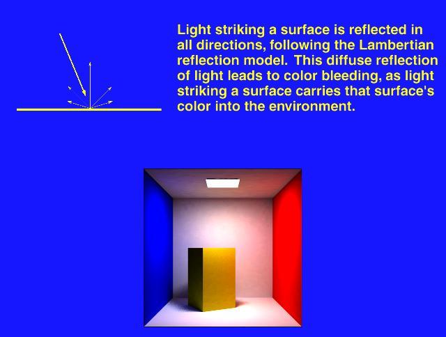
29 Radiosity Radiosity is a method of trying to simulate lighting effects using much more realistic models than were used previously: lighting simulation Closed environment: so light energy is conserved. All of the light energy is accounted for No need for an ambient light term anymore as what the ambient term simulated will now be specifically computed 29
30 Radiosity Radiosity is the rate at which energy leaves a surface (via emittance, reflectance or transmittance) Light interactions are computed first for the entire scene without regard for the viewpoint: diffuse reflection Generate images from any viewpoint 30
31 Radiosity Light sources are not treated as separate from the objects in the scene All objects emit light which can give more realistic effects when areas are giving off light rather than several discrete sources Space divided into n discrete finite sized patches which emit and reflect light uniformly over their area 31
32 Radiosity Equation B i = E i + p i n j=1 B jf ji (A j /A i ) Bi - radiosity of patch i Bj - radiosity of patch j Ei - rate at which light is emitted from patch i pi - reflectivity of patch i Fj-i - form factor (configuration factor) fraction of energy that leaves j and arrives at i Ai - area of patch i Aj - area of patch j 32
33 Radiosity So the radiosity of a unit area is the sum of the emitted light + reflected incident light Note that the summation includes patch i - that is an object can reflect light onto itself 33
34 Radiosity System B i p i n j=1 F ijb j = E i Rewrite the previous equation End up with a set of simultaneous equations to solve, one for each object in the scene: linear system to solve Since these equations have nothing to do with the users viewpoint there is no need to recompute if the user moves through the 34
35 35

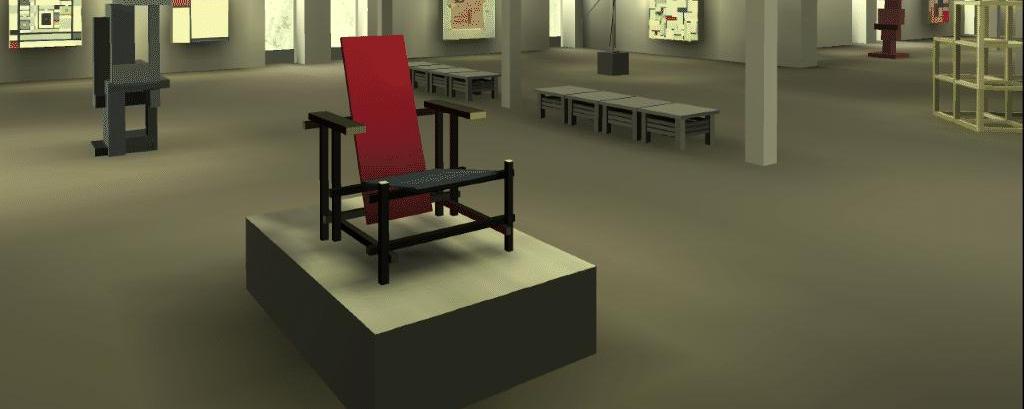

36 Example 36


37 Example 37
38 Special Topics (web) Stereopsis Virtual Reality Scientific Visualization Medical Visualization New devices GeoWall, Paris, Tiled display 38
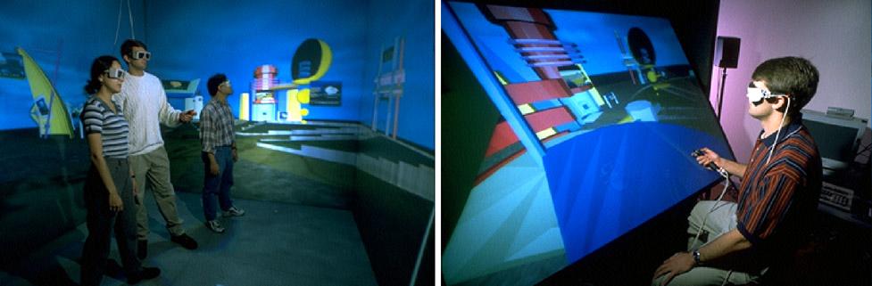


39 39
40 The END 40
41 Next CS Comp. Graphics II current topics in computer graphics - generally with students presenting papers from the most recent couple years of SIGGRAPH publications, and creating projects based around these ideas. CS Human-Computer Interaction CS Multi-Media Systems CS Computer Animation CS Virtual Reality 41
Computer Graphics. Lecture 13. Global Illumination 1: Ray Tracing and Radiosity. Taku Komura
 Computer Graphics Lecture 13 Global Illumination 1: Ray Tracing and Radiosity Taku Komura 1 Rendering techniques Can be classified as Local Illumination techniques Global Illumination techniques Local
Computer Graphics. Lecture 10. Global Illumination 1: Ray Tracing and Radiosity. Taku Komura 12/03/15
 Computer Graphics Lecture 10 Global Illumination 1: Ray Tracing and Radiosity Taku Komura 1 Rendering techniques Can be classified as Local Illumination techniques Global Illumination techniques Local
9. Illumination and Shading
 9. Illumination and Shading Approaches for visual realism: - Remove hidden surfaces - Shade visible surfaces and reproduce shadows - Reproduce surface properties Texture Degree of transparency Roughness,
Photorealism. Ray Tracing Texture Mapping Radiosity
 Photorealism Ray Tracing Texture Mapping Radiosity Photorealism -- Taking into Account Global Illumination Light can arrive at surfaces indirectly This light called global illumination To now we ve approximated
Homework #2. Shading, Ray Tracing, and Texture Mapping
 Computer Graphics Prof. Brian Curless CSE 457 Spring 2000 Homework #2 Shading, Ray Tracing, and Texture Mapping Prepared by: Doug Johnson, Maya Widyasari, and Brian Curless Assigned: Monday, May 8, 2000
Photorealism. Photorealism: Ray Tracing. Ray Tracing
 CS 460 Computer Graphics Professor Richard Eckert Ray Tracing Texture Mapping Radiosity Photorealism April 30, 2004 Photorealism -- Taking into Account Global Illumination Light can arrive at surfaces
CEng 477 Introduction to Computer Graphics Fall 2007
 Visible Surface Detection CEng 477 Introduction to Computer Graphics Fall 2007 Visible Surface Detection Visible surface detection or hidden surface removal. Realistic scenes: closer objects occludes the
Computer Graphics 1. Chapter 7 (June 17th, 2010, 2-4pm): Shading and rendering. LMU München Medieninformatik Andreas Butz Computergraphik 1 SS2010
: Shading and rendering. LMU München Medieninformatik Andreas Butz Computergraphik 1 SS2010") Computer Graphics 1 Chapter 7 (June 17th, 2010, 2-4pm): Shading and rendering 1 The 3D rendering pipeline (our version for this class) 3D models in model coordinates 3D models in world coordinates 2D Polygons
Computer Graphics 1 Chapter 7 (June 17th, 2010, 2-4pm): Shading and rendering 1 The 3D rendering pipeline (our version for this class) 3D models in model coordinates 3D models in world coordinates 2D Polygons
Lighting and Shading
 Lighting and Shading Today: Local Illumination Solving the rendering equation is too expensive First do local illumination Then hack in reflections and shadows Local Shading: Notation light intensity in,
Graphics for VEs. Ruth Aylett
 Graphics for VEs Ruth Aylett Overview VE Software Graphics for VEs The graphics pipeline Projections Lighting Shading VR software Two main types of software used: off-line authoring or modelling packages
Photorealism CS 460/560. Shadows Ray Tracing Texture Mapping Radiosity. Computer Graphics. Binghamton University. EngiNet. Thomas J.
 Binghamton University EngiNet State University of New York EngiNet Thomas J. Watson School of Engineering and Applied Science WARNING All rights reserved. No Part of this video lecture series may be reproduced
Computer Graphics. Lecture 14 Bump-mapping, Global Illumination (1)
") Computer Graphics Lecture 14 Bump-mapping, Global Illumination (1) Today - Bump mapping - Displacement mapping - Global Illumination Radiosity Bump Mapping - A method to increase the realism of 3D objects
Computer Graphics Lecture 14 Bump-mapping, Global Illumination (1) Today - Bump mapping - Displacement mapping - Global Illumination Radiosity Bump Mapping - A method to increase the realism of 3D objects
Pipeline Operations. CS 4620 Lecture 10
 Pipeline Operations CS 4620 Lecture 10 2008 Steve Marschner 1 Hidden surface elimination Goal is to figure out which color to make the pixels based on what s in front of what. Hidden surface elimination
CS5620 Intro to Computer Graphics
 So Far wireframe hidden surfaces Next step 1 2 Light! Need to understand: How lighting works Types of lights Types of surfaces How shading works Shading algorithms What s Missing? Lighting vs. Shading
Reflection and Shading
 Reflection and Shading R. J. Renka Department of Computer Science & Engineering University of North Texas 10/19/2015 Light Sources Realistic rendering requires that we model the interaction between light
CS 325 Computer Graphics
 CS 325 Computer Graphics 04 / 02 / 2012 Instructor: Michael Eckmann Today s Topics Questions? Comments? Illumination modelling Ambient, Diffuse, Specular Reflection Surface Rendering / Shading models Flat
CS130 : Computer Graphics Lecture 8: Lighting and Shading. Tamar Shinar Computer Science & Engineering UC Riverside
 CS130 : Computer Graphics Lecture 8: Lighting and Shading Tamar Shinar Computer Science & Engineering UC Riverside Why we need shading Suppose we build a model of a sphere using many polygons and color
Lighting. To do. Course Outline. This Lecture. Continue to work on ray programming assignment Start thinking about final project
 To do Continue to work on ray programming assignment Start thinking about final project Lighting Course Outline 3D Graphics Pipeline Modeling (Creating 3D Geometry) Mesh; modeling; sampling; Interaction
Topic 12: Texture Mapping. Motivation Sources of texture Texture coordinates Bump mapping, mip-mapping & env mapping
 Topic 12: Texture Mapping Motivation Sources of texture Texture coordinates Bump mapping, mip-mapping & env mapping Texture sources: Photographs Texture sources: Procedural Texture sources: Solid textures
So far, we have considered only local models of illumination; they only account for incident light coming directly from the light sources.
 11 11.1 Basics So far, we have considered only local models of illumination; they only account for incident light coming directly from the light sources. Global models include incident light that arrives
Illumination and Reflection in OpenGL CS 460/560. Computer Graphics. Shadows. Photo-Realism: Ray Tracing. Binghamton University.
 Binghamton University EngiNet State University of New York EngiNet Thomas J. Watson School of Engineering and Applied Science WARNING All rights reserved. No Part of this video lecture series may be reproduced
ECS 175 COMPUTER GRAPHICS. Ken Joy.! Winter 2014
 ECS 175 COMPUTER GRAPHICS Ken Joy Winter 2014 Shading To be able to model shading, we simplify Uniform Media no scattering of light Opaque Objects No Interreflection Point Light Sources RGB Color (eliminating
surface: reflectance transparency, opacity, translucency orientation illumination: location intensity wavelength point-source, diffuse source
 walters@buffalo.edu CSE 480/580 Lecture 18 Slide 1 Illumination and Shading Light reflected from nonluminous objects depends on: surface: reflectance transparency, opacity, translucency orientation illumination:
OpenGl Pipeline. triangles, lines, points, images. Per-vertex ops. Primitive assembly. Texturing. Rasterization. Per-fragment ops.
 OpenGl Pipeline Individual Vertices Transformed Vertices Commands Processor Per-vertex ops Primitive assembly triangles, lines, points, images Primitives Fragments Rasterization Texturing Per-fragment
Topic 11: Texture Mapping 11/13/2017. Texture sources: Solid textures. Texture sources: Synthesized
 Topic 11: Texture Mapping Motivation Sources of texture Texture coordinates Bump mapping, mip mapping & env mapping Texture sources: Photographs Texture sources: Procedural Texture sources: Solid textures
Topic 11: Texture Mapping 10/21/2015. Photographs. Solid textures. Procedural
 Topic 11: Texture Mapping Motivation Sources of texture Texture coordinates Bump mapping, mip mapping & env mapping Topic 11: Photographs Texture Mapping Motivation Sources of texture Texture coordinates
Rendering. Mike Bailey. Rendering.pptx. The Rendering Equation
 1 Rendering This work is licensed under a Creative Commons Attribution-NonCommercial-NoDerivatives 4.0 International License Mike Bailey mjb@cs.oregonstate.edu Rendering.pptx d i d 0 P P d i The Rendering
Virtual Reality for Human Computer Interaction
 Virtual Reality for Human Computer Interaction Appearance: Lighting Representation of Light and Color Do we need to represent all I! to represent a color C(I)? No we can approximate using a three-color
Illumination Models & Shading
 Illumination Models & Shading Lighting vs. Shading Lighting Interaction between materials and light sources Physics Shading Determining the color of a pixel Computer Graphics ZBuffer(Scene) PutColor(x,y,Col(P));
Interpolation using scanline algorithm
 Interpolation using scanline algorithm Idea: Exploit knowledge about already computed color values. Traverse projected triangle top-down using scanline. Compute start and end color value of each pixel
Chapter 7 - Light, Materials, Appearance
 Chapter 7 - Light, Materials, Appearance Types of light in nature and in CG Shadows Using lights in CG Illumination models Textures and maps Procedural surface descriptions Literature: E. Angel/D. Shreiner,
Topic 9: Lighting & Reflection models 9/10/2016. Spot the differences. Terminology. Two Components of Illumination. Ambient Light Source
 Topic 9: Lighting & Reflection models Lighting & reflection The Phong reflection model diffuse component ambient component specular component Spot the differences Terminology Illumination The transport
Graphics for VEs. Ruth Aylett
 Graphics for VEs Ruth Aylett Overview VE Software Graphics for VEs The graphics pipeline Projections Lighting Shading Runtime VR systems Two major parts: initialisation and update loop. Initialisation
COMP371 COMPUTER GRAPHICS
 COMP371 COMPUTER GRAPHICS SESSION 15 RAY TRACING 1 Announcements Programming Assignment 3 out today - overview @ end of the class Ray Tracing 2 Lecture Overview Review of last class Ray Tracing 3 Local
CS3500 Computer Graphics Module: Lighting and Shading
 Computer Graphics Module: Lighting and Shading P. J. Narayanan Spring 2009 We know which pixels of the frame buffer belongs to which object after visibility and scan conversion. What colour to give to
Topic 9: Lighting & Reflection models. Lighting & reflection The Phong reflection model diffuse component ambient component specular component
 Topic 9: Lighting & Reflection models Lighting & reflection The Phong reflection model diffuse component ambient component specular component Spot the differences Terminology Illumination The transport
Photorealistic 3D Rendering for VW in Mobile Devices
 Abstract University of Arkansas CSCE Department Advanced Virtual Worlds Spring 2013 Photorealistic 3D Rendering for VW in Mobile Devices Rafael Aroxa In the past few years, the demand for high performance
Ray Tracing. CSCI 420 Computer Graphics Lecture 15. Ray Casting Shadow Rays Reflection and Transmission [Ch ]
![Ray Tracing. CSCI 420 Computer Graphics Lecture 15. Ray Casting Shadow Rays Reflection and Transmission [Ch ]](/thumbs/78/78594982.jpg "Ray Tracing. CSCI 420 Computer Graphics Lecture 15. Ray Casting Shadow Rays Reflection and Transmission [Ch ]") CSCI 420 Computer Graphics Lecture 15 Ray Tracing Ray Casting Shadow Rays Reflection and Transmission [Ch. 13.2-13.3] Jernej Barbic University of Southern California 1 Local Illumination Object illuminations
CSCI 420 Computer Graphics Lecture 15 Ray Tracing Ray Casting Shadow Rays Reflection and Transmission [Ch. 13.2-13.3] Jernej Barbic University of Southern California 1 Local Illumination Object illuminations
Announcements. Written Assignment 2 out (due March 8) Computer Graphics
 Computer Graphics") Announcements Written Assignment 2 out (due March 8) 1 Advanced Ray Tracing (Recursive) Ray Tracing Antialiasing Motion Blur Distribution Ray Tracing Ray Tracing and Radiosity Assumptions Simple shading
Announcements Written Assignment 2 out (due March 8) 1 Advanced Ray Tracing (Recursive) Ray Tracing Antialiasing Motion Blur Distribution Ray Tracing Ray Tracing and Radiosity Assumptions Simple shading
COMP environment mapping Mar. 12, r = 2n(n v) v
 v") Rendering mirror surfaces The next texture mapping method assumes we have a mirror surface, or at least a reflectance function that contains a mirror component. Examples might be a car window or hood,
Rendering mirror surfaces The next texture mapping method assumes we have a mirror surface, or at least a reflectance function that contains a mirror component. Examples might be a car window or hood,
CS580: Ray Tracing. Sung-Eui Yoon ( 윤성의 ) Course URL:
 Course URL:") CS580: Ray Tracing Sung-Eui Yoon ( 윤성의 ) Course URL: http://sglab.kaist.ac.kr/~sungeui/gcg/ Recursive Ray Casting Gained popularity in when Turner Whitted (1980) recognized that recursive ray casting could
CS580: Ray Tracing Sung-Eui Yoon ( 윤성의 ) Course URL: http://sglab.kaist.ac.kr/~sungeui/gcg/ Recursive Ray Casting Gained popularity in when Turner Whitted (1980) recognized that recursive ray casting could
Consider a partially transparent object that is illuminated with two lights, one visible from each side of the object. Start with a ray from the eye
 Ray Tracing What was the rendering equation? Motivate & list the terms. Relate the rendering equation to forward ray tracing. Why is forward ray tracing not good for image formation? What is the difference
Global Illumination. CMPT 361 Introduction to Computer Graphics Torsten Möller. Machiraju/Zhang/Möller
 Global Illumination CMPT 361 Introduction to Computer Graphics Torsten Möller Reading Foley, van Dam (better): Chapter 16.7-13 Angel: Chapter 5.11, 11.1-11.5 2 Limitation of local illumination A concrete
Computer Graphics. Lecture 9 Environment mapping, Mirroring
 Computer Graphics Lecture 9 Environment mapping, Mirroring Today Environment Mapping Introduction Cubic mapping Sphere mapping refractive mapping Mirroring Introduction reflection first stencil buffer
Computer Graphics I Lecture 11
 15-462 Computer Graphics I Lecture 11 Midterm Review Assignment 3 Movie Midterm Review Midterm Preview February 26, 2002 Frank Pfenning Carnegie Mellon University http://www.cs.cmu.edu/~fp/courses/graphics/
Rendering and Radiosity. Introduction to Design Media Lecture 4 John Lee
 Rendering and Radiosity Introduction to Design Media Lecture 4 John Lee Overview Rendering is the process that creates an image from a model How is it done? How has it been developed? What are the issues
COMP 175 COMPUTER GRAPHICS. Lecture 11: Recursive Ray Tracer. COMP 175: Computer Graphics April 9, Erik Anderson 11 Recursive Ray Tracer
 Lecture 11: Recursive Ray Tracer COMP 175: Computer Graphics April 9, 2018 1/40 Note on using Libraries } C++ STL } Does not always have the same performance. } Interface is (mostly) the same, but implementations
I have a meeting with Peter Lee and Bob Cosgrove on Wednesday to discuss the future of the cluster. Computer Graphics
 Announcements Assignment 4 will be out later today Problem Set 3 is due today or tomorrow by 9am in my mail box (4 th floor NSH) How are the machines working out? I have a meeting with Peter Lee and Bob
University of Victoria CSC 305 Shading. Brian Wyvill 2016
 University of Victoria CSC 305 Shading Brian Wyvill 2016 The illuminating Hemisphere Energy and Intensity Energy is the intensity integrated over the solid angle through which it acts. Intensity is not
Page 1. Area-Subdivision Algorithms z-buffer Algorithm List Priority Algorithms BSP (Binary Space Partitioning Tree) Scan-line Algorithms
 Scan-line Algorithms") Visible Surface Determination Visibility Culling Area-Subdivision Algorithms z-buffer Algorithm List Priority Algorithms BSP (Binary Space Partitioning Tree) Scan-line Algorithms Divide-and-conquer strategy:
Visible Surface Determination Visibility Culling Area-Subdivision Algorithms z-buffer Algorithm List Priority Algorithms BSP (Binary Space Partitioning Tree) Scan-line Algorithms Divide-and-conquer strategy:
General Hidden Surface Removal Algorithms. Binghamton University. EngiNet. Thomas J. Watson. School of Engineering and Applied Science CS 460/560
 Binghamton University EngiNet State University of New York EngiNet Thomas J. Watson School of Engineering and Applied Science WARNING All rights reserved. No Part of this video lecture series may be reproduced
Recursive Ray Tracing. Ron Goldman Department of Computer Science Rice University
 Recursive Ray Tracing Ron Goldman Department of Computer Science Rice University Setup 1. Eye Point 2. Viewing Screen 3. Light Sources 4. Objects in Scene a. Reflectivity b. Transparency c. Index of Refraction
Ray Tracing. Kjetil Babington
 Ray Tracing Kjetil Babington 21.10.2011 1 Introduction What is Ray Tracing? Act of tracing a ray through some scene Not necessarily for rendering Rendering with Ray Tracing Ray Tracing is a global illumination
Announcements. Written Assignment 2 is out see the web page. Computer Graphics
 Announcements Written Assignment 2 is out see the web page 1 Texture and other Mappings Shadows Texture Mapping Bump Mapping Displacement Mapping Environment Mapping Watt Chapter 8 COMPUTER GRAPHICS 15-462
Recollection. Models Pixels. Model transformation Viewport transformation Clipping Rasterization Texturing + Lights & shadows
 Recollection Models Pixels Model transformation Viewport transformation Clipping Rasterization Texturing + Lights & shadows Can be computed in different stages 1 So far we came to Geometry model 3 Surface
Rasterization. MIT EECS Frédo Durand and Barb Cutler. MIT EECS 6.837, Cutler and Durand 1
 Rasterization MIT EECS 6.837 Frédo Durand and Barb Cutler MIT EECS 6.837, Cutler and Durand 1 Final projects Rest of semester Weekly meetings with TAs Office hours on appointment This week, with TAs Refine
Lecture 17: Recursive Ray Tracing. Where is the way where light dwelleth? Job 38:19
 Lecture 17: Recursive Ray Tracing Where is the way where light dwelleth? Job 38:19 1. Raster Graphics Typical graphics terminals today are raster displays. A raster display renders a picture scan line
Visible-Surface Detection Methods. Chapter? Intro. to Computer Graphics Spring 2008, Y. G. Shin
 Visible-Surface Detection Methods Chapter? Intro. to Computer Graphics Spring 2008, Y. G. Shin The Visibility Problem [Problem Statement] GIVEN: a set of 3-D surfaces, a projection from 3-D to 2-D screen,
Illumination and Shading
 Illumination and Shading Illumination (Lighting)! Model the interaction of light with surface points to determine their final color and brightness! The illumination can be computed either at vertices or
Topics and things to know about them:
 Practice Final CMSC 427 Distributed Tuesday, December 11, 2007 Review Session, Monday, December 17, 5:00pm, 4424 AV Williams Final: 10:30 AM Wednesday, December 19, 2007 General Guidelines: The final will
w Foley, Section16.1 Reading
 Shading w Foley, Section16.1 Reading Introduction So far, we ve talked exclusively about geometry. w What is the shape of an object? w How do I place it in a virtual 3D space? w How do I know which pixels
03 RENDERING PART TWO
 03 RENDERING PART TWO WHAT WE HAVE SO FAR: GEOMETRY AFTER TRANSFORMATION AND SOME BASIC CLIPPING / CULLING TEXTURES AND MAPPING MATERIAL VISUALLY DISTINGUISHES 2 OBJECTS WITH IDENTICAL GEOMETRY FOR NOW,
Lighting. Figure 10.1
 We have learned to build three-dimensional graphical models and to display them. However, if you render one of our models, you might be disappointed to see images that look flat and thus fail to show the
Global Rendering. Ingela Nyström 1. Effects needed for realism. The Rendering Equation. Local vs global rendering. Light-material interaction
 Effects needed for realism Global Rendering Computer Graphics 1, Fall 2005 Lecture 7 4th ed.: Ch 6.10, 12.1-12.5 Shadows Reflections (Mirrors) Transparency Interreflections Detail (Textures etc.) Complex
Raytracing. COSC 4328/5327 Scott A. King
 Raytracing COSC 4328/5327 Scott A. King Basic Ray Casting Method pixels in screen Shoot ray p from the eye through the pixel. Find closest ray-object intersection. Get color at intersection Basic Ray Casting
Computer Graphics. Illumination Models and Surface-Rendering Methods. Somsak Walairacht, Computer Engineering, KMITL
 Computer Graphics Chapter 10 llumination Models and Surface-Rendering Methods Somsak Walairacht, Computer Engineering, KMTL Outline Light Sources Surface Lighting Effects Basic llumination Models Polygon
Introduction Rasterization Z-buffering Shading. Graphics 2012/2013, 4th quarter. Lecture 09: graphics pipeline (rasterization and shading)
") Lecture 9 Graphics pipeline (rasterization and shading) Graphics pipeline - part 1 (recap) Perspective projection by matrix multiplication: x pixel y pixel z canonical 1 x = M vpm per M cam y z 1 This
Lecture 9 Graphics pipeline (rasterization and shading) Graphics pipeline - part 1 (recap) Perspective projection by matrix multiplication: x pixel y pixel z canonical 1 x = M vpm per M cam y z 1 This
Visible Surface Detection Methods
 Visible urface Detection Methods Visible-urface Detection identifying visible parts of a scene (also hidden- elimination) type of algorithm depends on: complexity of scene type of objects available equipment
Local vs. Global Illumination & Radiosity
 Last Time? Local vs. Global Illumination & Radiosity Ray Casting & Ray-Object Intersection Recursive Ray Tracing Distributed Ray Tracing An early application of radiative heat transfer in stables. Reading
graphics pipeline computer graphics graphics pipeline 2009 fabio pellacini 1
 graphics pipeline computer graphics graphics pipeline 2009 fabio pellacini 1 graphics pipeline sequence of operations to generate an image using object-order processing primitives processed one-at-a-time
Chapter 10. Surface-Rendering Methods. Somsak Walairacht, Computer Engineering, KMITL
 Computer Graphics Chapter 10 llumination Models and Surface-Rendering Methods Somsak Walairacht, Computer Engineering, KMTL 1 Outline Light Sources Surface Lighting Effects Basic llumination Models Polygon
graphics pipeline computer graphics graphics pipeline 2009 fabio pellacini 1
 graphics pipeline computer graphics graphics pipeline 2009 fabio pellacini 1 graphics pipeline sequence of operations to generate an image using object-order processing primitives processed one-at-a-time
Pipeline Operations. CS 4620 Lecture Steve Marschner. Cornell CS4620 Spring 2018 Lecture 11
 Pipeline Operations CS 4620 Lecture 11 1 Pipeline you are here APPLICATION COMMAND STREAM 3D transformations; shading VERTEX PROCESSING TRANSFORMED GEOMETRY conversion of primitives to pixels RASTERIZATION
Movie: For The Birds. Announcements. Ray Tracing 1. Programming 2 Recap. Programming 3 Info Test data for part 1 (Lines) is available
 is available") Now Playing: Movie: For The Birds Pixar, 2000 Liar Built To Spill from You In Reverse Released April 11, 2006 Ray Tracing 1 Rick Skarbez, Instructor COMP 575 November 1, 2007 Announcements Programming
Now Playing: Movie: For The Birds Pixar, 2000 Liar Built To Spill from You In Reverse Released April 11, 2006 Ray Tracing 1 Rick Skarbez, Instructor COMP 575 November 1, 2007 Announcements Programming
lecture 18 - ray tracing - environment mapping - refraction
 lecture 18 - ray tracing - environment mapping - refraction Recall Ray Casting (lectures 7, 8) for each pixel (x,y) { cast a ray through that pixel into the scene, and find the closest surface along the
Computer Graphics. Shadows
 Computer Graphics Lecture 10 Shadows Taku Komura Today Shadows Overview Projective shadows Shadow texture Shadow volume Shadow map Soft shadows Why Shadows? Shadows tell us about the relative locations
RASTERISED RENDERING
 DH2323 DGI16 INTRODUCTION TO COMPUTER GRAPHICS AND INTERACTION RASTERISED RENDERING Christopher Peters HPCViz, KTH Royal Institute of Technology, Sweden chpeters@kth.se http://kth.academia.edu/christopheredwardpeters
3D Rasterization II COS 426
 3D Rasterization II COS 426 3D Rendering Pipeline (for direct illumination) 3D Primitives Modeling Transformation Lighting Viewing Transformation Projection Transformation Clipping Viewport Transformation
Sung-Eui Yoon ( 윤성의 )
") CS380: Computer Graphics Ray Tracing Sung-Eui Yoon ( 윤성의 ) Course URL: http://sglab.kaist.ac.kr/~sungeui/cg/ Class Objectives Understand overall algorithm of recursive ray tracing Ray generations Intersection
CS380: Computer Graphics Ray Tracing Sung-Eui Yoon ( 윤성의 ) Course URL: http://sglab.kaist.ac.kr/~sungeui/cg/ Class Objectives Understand overall algorithm of recursive ray tracing Ray generations Intersection
Pipeline Operations. CS 4620 Lecture 14
 Pipeline Operations CS 4620 Lecture 14 2014 Steve Marschner 1 Pipeline you are here APPLICATION COMMAND STREAM 3D transformations; shading VERTEX PROCESSING TRANSFORMED GEOMETRY conversion of primitives
Lighting and Reflectance COS 426
 ighting and Reflectance COS 426 Ray Casting R2mage *RayCast(R3Scene *scene, int width, int height) { R2mage *image = new R2mage(width, height); for (int i = 0; i < width; i++) { for (int j = 0; j < height;
Questions??? Announcements Assignment 3 due today
 Announcements Assignment 3 due today Questions??? Remember that you have late days (if you haven t used them yet ) Problem set 3 out at the end of the day Movie for Assignment 2 at the end of class 1 Ray
Graphics Hardware and Display Devices
 Graphics Hardware and Display Devices CSE328 Lectures Graphics/Visualization Hardware Many graphics/visualization algorithms can be implemented efficiently and inexpensively in hardware Facilitates interactive
A Little Background. Motivation. Motivation
 A Little Background Ray casting Process of shooting rays into scene to get pixel colors Nonrecursive, i.e., no interreflections Origin: Arthur Appel, 1968 (earlier work by others for nonrendering) Ray
Raytracing & Epsilon. Today. Last Time? Forward Ray Tracing. Does Ray Tracing Simulate Physics? Local Illumination
 Raytracing & Epsilon intersects light @ t = 25.2 intersects sphere1 @ t = -0.01 & Monte Carlo Ray Tracing intersects sphere1 @ t = 10.6 Solution: advance the ray start position epsilon distance along the
Local Illumination. CMPT 361 Introduction to Computer Graphics Torsten Möller. Machiraju/Zhang/Möller
 Local Illumination CMPT 361 Introduction to Computer Graphics Torsten Möller Graphics Pipeline Hardware Modelling Transform Visibility Illumination + Shading Perception, Interaction Color Texture/ Realism
CSE528 Computer Graphics: Theory, Algorithms, and Applications
 CSE528 Computer Graphics: Theory, Algorithms, and Applications Hong Qin State University of New York at Stony Brook (Stony Brook University) Stony Brook, New York 11794--4400 Tel: (631)632-8450; Fax: (631)632-8334
Review for Ray-tracing Algorithm and Hardware
 Review for Ray-tracing Algorithm and Hardware Reporter: 邱敬捷博士候選人 Lan-Da Van ( 范倫達 ), Ph. D. Department of Computer Science National Chiao Tung University Taiwan, R.O.C. Summer, 2017 1 2017/7/26 Outline
Computer Graphics 10 - Shadows
 Computer Graphics 10 - Shadows Tom Thorne Slides courtesy of Taku Komura www.inf.ed.ac.uk/teaching/courses/cg Overview Shadows Overview Projective shadows Shadow textures Shadow volume Shadow map Soft
Homework 3: Shading, Raytracing, and Image Processing
 Computer Graphics CSE 457, Spring 1999 Craig Kaplan Douglas Zongker Homework 3: Shading, Raytracing, and Image Processing Received: Friday May 7, 1999 Due: Friday May 21, 1999 DIRECTIONS Please provide
Today s class. Simple shadows Shading Lighting in OpenGL. Informationsteknologi. Wednesday, November 21, 2007 Computer Graphics - Class 10 1
 Today s class Simple shadows Shading Lighting in OpenGL Wednesday, November 21, 27 Computer Graphics - Class 1 1 Simple shadows Simple shadows can be gotten by using projection matrices Consider a light
Illumination and Shading
 Illumination and Shading Computer Graphics COMP 770 (236) Spring 2007 Instructor: Brandon Lloyd 2/14/07 1 From last time Texture mapping overview notation wrapping Perspective-correct interpolation Texture
The Rendering Equation & Monte Carlo Ray Tracing
 Last Time? Local Illumination & Monte Carlo Ray Tracing BRDF Ideal Diffuse Reflectance Ideal Specular Reflectance The Phong Model Radiosity Equation/Matrix Calculating the Form Factors Aj Ai Reading for
Advanced Graphics. Global Illumination. Alex Benton, University of Cambridge Supported in part by Google UK, Ltd
 Advanced Graphics Global Illumination 1 Alex Benton, University of Cambridge A.Benton@damtp.cam.ac.uk Supported in part by Google UK, Ltd What s wrong with raytracing? Soft shadows are expensive Shadows
Lighting and Shading Computer Graphics I Lecture 7. Light Sources Phong Illumination Model Normal Vectors [Angel, Ch
 15-462 Computer Graphics I Lecture 7 Lighting and Shading February 12, 2002 Frank Pfenning Carnegie Mellon University http://www.cs.cmu.edu/~fp/courses/graphics/ Light Sources Phong Illumination Model
Illumination Algorithms
 Global Illumination Illumination Algorithms Digital Lighting and Rendering CGT 340 The goal of global illumination is to model all possible paths of light to the camera. Global Illumination Global illumination
Introduction to Visualization and Computer Graphics
 Introduction to Visualization and Computer Graphics DH2320, Fall 2015 Prof. Dr. Tino Weinkauf Introduction to Visualization and Computer Graphics Visibility Shading 3D Rendering Geometric Model Color Perspective
Rendering. Converting a 3D scene to a 2D image. Camera. Light. Rendering. View Plane
 Rendering Pipeline Rendering Converting a 3D scene to a 2D image Rendering Light Camera 3D Model View Plane Rendering Converting a 3D scene to a 2D image Basic rendering tasks: Modeling: creating the world
Global Illumination. COMP 575/770 Spring 2013
 Global Illumination COMP 575/770 Spring 2013 Final Exam and Projects COMP 575 Final Exam Friday, May 3 4:00 pm COMP 770 (and 575 extra credit) Projects Final report due by end of day, May 1 Presentations:
Raytracing CS148 AS3. Due :59pm PDT
 Raytracing CS148 AS3 Due 2010-07-25 11:59pm PDT We start our exploration of Rendering - the process of converting a high-level object-based description of scene into an image. We will do this by building