WTP-100. Thermal Receipt printer Technical manual. SEWOO TECH CO., LTD.
|
|
|
- Brooke Fleming
- 5 years ago
- Views:
Transcription
1 WTP-100 Thermal Receipt printer Technical manual SEWOO TECH CO., LTD.
2 TABLE OF CONTENTS 1. General Specifications 1.1 Printing Specifications 1.2 Character Specifications 1.3 Auto Cutter 1.4 Paper Roll Supply Device 1.5 Paper Specifications 1.6 Printable Area 1.7 Printing and Cutting Positions 1.8 Internal Buffer 1.9 Electrical Characteristics 1.10 EMI and Safety Standards Applied 1.11 Reliability 1.12 Environmental Conditions 2. Configuration 2.1 Interface RS-232 serial interface Specifications Switching between on-line and off-line Interface connector terminal assignments and signal functions Serial interface connection example Centronics parallel interface Data Receiving Timing(Compatibility Mode) USB Interface Interface Connector 3. Connectors 3.1 Interface Connectors 3.2 Electrical Characteristics 3.3 Drawer kick-out Connector (Modular Connector) 4. Control Command Summary Page2
3 1. General Specifications 1.1 Printing Specifications 1) Printing method: Thermal line printing 2) Dot density: 180dpi x 180dpi 3) Printing direction: Unidirectional with friction feed 4) Printing width: 72mm(2.83"), 512 dot positions 5) Characters per line(default): Font A: 42 Font B: 56 6) Printing speed: High speed mode: 35.5lines/second maximum (1/6inch feed) (at 24V, 20 ) Approximately 150mm/sec maximum (approximately 5.9inchs/sec maximum) NOTE: Speeds are switched depending on the applied voltage to the printer and head temperature conditions automatically. NOTE: There may be variations in printing after switching the mode of the printing speed. To prevent this for logo printing with ESC* command, using a downloaded bit image is recommended. Change in printing speed does not occur during down loaded bit image printing. 7) Line spacing (default): 1/6 inch (4.23mm) Programmable by control command. Page3
4 1.2 Character Specifications 1) Number of characters: Alphanumeric characters: 95 Extended graphics pages (including one space page) International characters: 32 1 English 2 Hangul 3 Chinese (GB2312,Big5) 4 Kanji 2) Character structure: Font A: 12 ⅹ 24 Font B: 9 ⅹ 24 Hangul, Chinese: 24 ⅹ 24 Font A is selected as the default 3) Character size: Standard Double-height Double-width WⅹH(mm) CPL WⅹH(mm) CPL WⅹH(mm) CPL Double-width / Double-height WⅹH FontA 12ⅹ ⅹ ⅹ ⅹ ⅹ FontB 9ⅹ ⅹ ⅹ ⅹ ⅹ Hangul, GB 24ⅹ ⅹ ⅹ ⅹ ⅹ Space between characters is not included. CPL = Characters per line 1.3 Auto Cutter Partial cut: Cutting with one point center uncut NOTE: To prevent dot displacement, after cutting, paper must be fed approximately 1mm(14/360 inches) or more before printing. (mm) CPL 1.4 Paper Roll Supply Device 1) Supply method: Drop-in paper roll 1.5 Paper Specification 1) Paper type: Specified thermal paper 2) Form: Paper roll 3) Paper width: 79.5 ± 0.5mm(3.13"±0.02") 4) Paper roll size: Roll diameter : Maximum 83mm Take-up paper roll width: 80 ± 0.5, 1.0mm(3.15"± 0.020", 0.04") 5) Paper roll spool diameter: Inside: 12mm(.47") Outside: 18mm(.71") NOTE: Paper must not be pasted to the paper roll spool. Page4
5 1.6 Printable Area 1) Paper roll The printable area of a paper with width of 79.5± 0.5mm(3.13"±0.02") is 72.2 ± 0.2mm(2.84"±0.008")(512dots) and the space on the right and left sides are approximately 3.7 ± 2mm(0.15"±0.079"). a=79.5±0.5mm(3.13"±0.02") b=0.141mm±0.05mm(.056"±.002") c=72.2mm±0.2mm(2.84±.008") d=3.7±0.2mm(0.15"±0.079") e=3.7±0.2mm(0.15"±0.079") [All the numeric values are typical.] < Figure 1.1 Paper Roll Printable Area > 1.7 Printing and Cutting Positions < Figure 1.2 Printing and Cutting Positions > NOTE: Numeric values used here are typical values; the values may vary slightly as a result of paper slack or variations in the paper. Take the notice into account when setting the cutting position of the auto-cutter. 1.8 Internal Buffer 1) Receive buffer: 4kbyte 1.9 Electrical Characteristics 1) Supply voltage: +24 VDC ± 7% 2) Current consumption (at 24V): Operating: Approx. 1.5A(at ASCII Printing) Peak:Approx. 10A(at print duty 100%, For 10 seconds or less) Stand-by: Approx. 0.15A Page5
6 1.10 EMI and Safety Standards Applied 1) Europe: EMI EN55022 CLASS A EMS EN , EN , EN Safety Standard: EN ) North America: EMI - FCC Part#15 Class A Safety Standards- UL(1950), c-ul(no.950) 1.11 Reliability 1) MCBF: 50 million lines (based on an average printing rate of 12.5% with paper thickness in the range 65 μm to 75 μm ). 35 million lines (based on an average printing rate of 12.5% with paper thickness in the range 76 μm to 150 μm ) 2) Cutter Life: 1.0 million cuttings (if the paper thickness is between 65 and 100 μm ) 1.12 Environmental Conditions 1) Temperature: Operating: 5 to 45 C Storage: -20 to 60 C (except for paper) 2) Humidity: Operating: 10 to 90%RH Storage: 10 to 90%RH (except for paper) Page6
7 2. Configuration 2.1 Interface RS-232 serial interface Specifications Data transmission: Serial Synchronization: Asynchronous Handshaking: DTR/DSR or XON/XOFF control Signal levels: MARK= -3 to 15V: Logic 1 SPACE= +3 to +15V: Logic 0 Baud rage: 4800, 9600, 19200, bps Data word length: 7 or 8 bits Parity Settings: None, even, odd Stop bits: 1 or more Connector (printer side): Female DSUB-25 pin connector NOTE: The data word length, baud rate, and parity depend on the DIPswitch settings Switching between on-line and off-line The printer does not have an on-line/off-line switch. The printer goes off-line: Between when the power is turned on (including reset using the interface) and when the printer is ready to receive data. During the self-test. When the cover is open. During paper feeding using the paper feed button. When the printer stops printing due to a paper-end (in cases when an empty paper supply is detected by either paper roll end detector or the paper roll near-end detector with a printing halt feature by ESC c4). During macro executing stand by status. When a temporary abnormality occurs in the power supply voltage. When an error has occurred Interface connector terminal assignments and signal functions PIN SIGNAL I/O DESCRIPTION 2 TXD - Printer transmit data line RS-232C level 3 RXD - Printer receive data line RS-232C level 4, 20 DTR Output Printer handshake to host line RS-232C level 6 DSR Input Data Send Ready 1,7 GND - System Ground Page7
8 2.1.5 Serial interface connection example Host side Printer side TXD RXD DSR DTR RXD TXD DTR DSR FG FG SG SG NOTES: Set the handshaking so that the transmit data can be received. Transmit data to the printer after turning on the power and initializing the printer. 1Bit 7 or 8 Bit None or 1 Bit 1 or 2 Bit < Figure 2.1 Serial transmission bit frame > < Figure 2.2 Line transmission with protocol > Page8
9 2.1.6 Centronics parallel interface PIN SIGNAL I/O DESCRIPTION 1 STROBE- Input Synchronize signal Data received 2-9 DATA0-7 Input Data bit Transmitted ACK- Output Data receiving competed 11 BUSY Output Impossible to printer data receiving 12 PE Output Paper empty 13 SELECT Output Printer s status for ON/OFF line 14 AUTO FEED- Input ND 15 GROUND - System Ground 16 GROUND - System Ground 17 NC - 18 LOGIC-H - +5V GROUND - System Ground 31 INIT- Input Initialize 32 ERROR- Output Printer Error 33 GROUND - System Ground 34 NC V - +5V 36 SELECT IN- Input ND Page9
10 1) Specifications Data transmission: Synchronization: Handshaking: Connector: 8-bit parallel STROBE pulse supplied by host computer. ACK and BUSY D-SUB 36(female) or equivalent DATA Data n Data n+1 nstrobe thold tsetup tstb Busy tready tbusy Peripheral Busy nack treply tack tnbusy tnext Data Receiving Timing (Compatibility Mode) Characteristics Symbol Specifications Min [ns] Max [ns] Data Hold Time (host) thold Data Setup Time tsetup STROBE Pulse Width tstb READY Cycle Idle Time tready 0 -- BUSY Output Delay Time tbusy Data Processing Time treply 0 ACKNLG Pulse Width tack us BUSY Release Time tnbusy 0 ACK Cycle Idle Time tnext 0 -- *The printer latches data at a nstrobe timing Page10
11 2.1.8 USB Interface PIN SIGNAL I/O DESCRIPTION 1 +5V - +5V 2 DATA- - Printer transmit data line 3 DATA+ - Printer transmit data line 4 GND - System Ground 1) Specifications Data transmission: USB 2.0 Connector: USB B type connector 2) USB interface connection example Host side Printer side VCC VCC DATA+ DATA+ DATA- DATA- GND GND Interface Connector <D-SUB 25 Female Serial Port> <D-SUB Centronics Parallel Port> Page11
12 3. Connectors 3.1 Interface Connectors Refer to Section 2.1, Interface 3.2 Electrical Characteristics 1) Input Voltage: DC 24V ± 10% 2) Current Consumption: Operating: Approx. 1.5 A (at ASC printing) Peak: Approx. 10 A (at print duty 100%, For 10 seconds or less) Stand-by: Approx A 3) Power Connector Page12
13 3.3 Drawer Kick-out Connector (Modular Connector) The pulse specified by ESC p or DLE DC4 is output to this connector. The host can confirm the status of the input signal by using the DLE EOT, GS a, or GS r commands. 1) Pin assignments: Refer to Table ) Connector model: Printer side: DAEEUN DEK-623PCB-6-B or Equivalent User side: 6-position 6-contact (RJ12telephone jack) < Drawer Kick-out Connector Pin Assignments > Pin Number Signal Name Direction 1 Frame GND - 2 Drawer kick-out drive signal 1 Output 3 Drawer open/close signal Input 4 +24V - 5 Drawer kick-out drive signal 2 Output 6 Signal GND - +24V is output through pin 4 when the power is turned on. However, pin 4 must by used only for the drawer. < Figure 3.1 Drawer Kick-out Connector > 3) Drawer kick-out drive signal Output signal: Output voltage: Approximately 24V Output current: 1A or less CAUTION: To avoid an overcurrent, the resistance of the drawer kick-out solenoid must be 24 Ω or more. Output waveform: Outputs the waveforms in Figure 3.2 to the points A and B in Figure 3.3 t1 (ON time) and t2 (OFF time) are specified by ESC p or DLE DC4. Page13
14 < Figure 3.2 Drawer Kick-out Drive Signal Output Waveform > 4) Drawer open/close signal Input signal level (connector pin 3): L = 0 to 0.8V H = 3 to 5V < Figure 3.3 Drawer Circuitry > NOTE: 1. Use a shielded cable for the drawer connector cable. 2. Two driver transistors cannot be energized simultaneously. 3. The drawer drive duty must by as shown below. ON time 0.2 (ON time + OFF time) 4. Be sure to use the printer power supply (connector pin 4) for the drawer power source. 5. The resistance of the drawer kick-out solenoid must not be less than the specified. Otherwise, an overcurrent could damage the solenoid. 6. Do not connect telecommunication network to the drawer kick-out connector. Page14
15 4. Controle Command summary No. Command Function 1 HT Horizontal tab 2 LF Print and line feed 3 CR Print and carriage return 4 FF Print end position label to start printing 5 CAN Cancel print data in page mode 6 DLE EOT Real-time status transmission 7 DLE ENQ Real-time request to printer 8 DLE DC4 Generate pulse at real-time 9 ESC FF Print data in page mode 10 ESC SP Set character right-side spacing 11 ESC! Set print mode 12 ESC $ Select/cancel user-defined character set 13 ESC % Define user-defined characters 14 ESC & Turn underline mode on/off 15 ESC * Set bit image mode 16 ESC - Turn underline mode on/off 17 ESC 2 Set 1/6 inch line spacing 18 ESC 3 Set line spacing using minimum units 19 ESC = Select peripheral device 20 ESC? Cancel user-defined characters 21 Initialize printer 22 ESC D Set horizontal tab positions 23 ESC E Select emphasized mode 24 ESC G Select double-strike mode 25 ESC J Print end feed paper using minimum units 26 ESC L Select page mode 27 ESC M Select character font 28 ESC R Select international character set 29 ESC S Select standard mode 30 ESC T Select print direction in page mode 31 ESC V Set/cancel 90 cw rotated character 32 ESC W Set printing area in page mode 33 ESC \ Set relative position 34 ESC a Align position 35 ESC c 3 Select paper sensor(s) to output paper-end signals 36 ESC c 4 Select paper sensor(s) to stop printing 37 ESC c 5 Enable/disable panel buttons 38 ESC d Print and feed paper n lines 39 ESC p General pulse 40 ESC t Select character code table Page15
16 41 ESC { Set/cancel upside-down character printing 42 FS p Print NV bit image 43 FS q Define NV bit image 44 GS! Select character size 45 GS $ Set absolute vertical print position in page mode 46 GS * Define downloaded bit image 47 GS / Print down-loaded bit image 48 GS : Start/end macro definition Not avalible 49 GS B Turn white/black reverse printing mode on/off 50 GS H Select printing position of HRI characters 51 GS I Transmit printer ID 52 GS L Set left margin 53 GS P Set horizontal and vertical motion units 54 GS V Cut paper 55 GS W Set printing area width 56 GS \ Set relative vertical print position in page mode 57 GS ^ Execute macro Not avalible 58 GS a Enable/disable Automatic Status Back(ASB) 59 GS b Turn smooting mode on/off Not avalible 60 GS f Select font for HRI characters 61 GS h Set bar code height 62 GS k Print bar code 63 GS r Transmit status 64 GS v 0 Print raster bit image 65 GS w Set bar code width < Add > 1 ESC i Full cut 2 ESC m Partial cut Page16
17 Command Descriptions Command Notation The name of the control command. [Format] [Range] [Default] [Reference] [Example] The code sequence. In this description, < > H denotes hexadecimal numbers, < >denotes decimal numbers and < > B denotes binary numbers. [ ] k indicates the contents of the [ ] should be repeated k times. The allowable range for the arguments. Description of the command function. If necessary provides important information on setting and using the printer command. The default values for the commands. List related commands. Example of using the commands. The numbers denoted by <>H is hexadecimal. The numbers denoted by <>B is binary. Page17
18 Print Commands The WTP series supports the following commands for printing characters and advancing paper. HT Horizontal tab [Format] ASCII HT Hex 09 Decimal 9 Moves the print position to the next tab position. This command is ignored unless the next tab position has been set. Horizontal tab positions are set using ESC D. If this command is received when the printing position is at [printing area width +1], the printer executes print buffer-full printing of the current line and horizontal tab processing from the beginning of the next line. [Reference] ESC D LF Print and line feed [Format] ASCII LF Hex 0A Decimal 10 LF prints the data in the print buffer and feeds one line. The amount of paper fed per line is based on the value set using the line spacing command. The default setting is 1/6 inch. [Reference] ESC 2, ESC 3 CR Print and carriage return. Page18
19 [Format] ASCII CR Hex 0D Decimal 13 [Reference] When auto line feed is enabled, this command functions in the same way as LF. When auto line feed is disabled, this command is ignored. This command sets the print position to the beginning of the line. This command is available only with a parallel interface and is ignored with a serial interface. FF Print and return to standard mode (in page mode). [Format] ASCII FF Hex 0C Decimal 12 [Reference] FF prints the data in the print buffer and returns to standard mode. The printing area set by ESC W is reset to the default setting. This command is effective only when page mode is selected. All data are cleared after printing. This command sets the print position to the beginning of the line. ESC FF, ESC L, ESC S CAN Cancel print data in page mode [Format] ASCII CAN Hex 18 Decimal 24 In page mode, delete all the print data in the current printable area. This command is enabled only in page mode. If data that existed in the reviously specified printable area also exists in the currently specified printable area, it is deleted. Page19
20 DLE EOT n Real-time status transmission. [Format] ASCII DLE EOT n Hex n Decimal 16 4 n [Range] 1 n 4 Transmits the selected printer status specified by n in real-time, according to the following parameters: n=1 : Transmit printer status n=2 : Transmit off-line status n=3 : Transmit error status n=4 : Transmit paper roll sensor status The status is transmitted whenever the data sequence of <10>H<04>H<n> (1 n 4) is received. Example: In ESC * m nl nh d1...dk, d1=<10>h, d2=<04>h, d3=<01>h This command should not be used within the data sequence of another command that consists of 2 or more bytes. Example: If you attempt to transmit ESC 3 n to the printer, but DTR (DSR for the host computer) goes to MARK before n is transmitted and then DLE EOT 3 interrupts before n is received, the code <10>H for DLE EOT 3 is processed as the code for ESC 3 <10>H. Even though the printer is not selected using ESC = (select peripheral device), this command is effective. The printer transmits the current status. Each status is represented by one-byte data. The printer transmits the status without confirming whether the host computer can receive data. The printer executes this command upon receiving it. This command is executed even when the printer is off-line, the receive buffer is full, or there is an error status with a serial interface model. With a parallel interface model, this command can not be executed when the printer is busy. This command is executed even when the printer is off-line or there is an error status when DIP switch 2-1 is on with a parallel interface model. When Auto Status Back (ASB) is enabled using the GS a command, the status transmitted by the DLE EOT command and the ASB status must be differentiated. Page20
21 n = 1: Printer status Bit Off/On Hex Decimal Function 0 Off 00 0 Not used. Fixed to Off 1 On 02 2 Not used. Fixed to On 2 Off 00 0 Drawer open/close signal is LOW (connector pin 3). On 04 4 Drawer open/close signal is HIGH (connector pin 3). 3 Off 00 0 On-line On 08 8 Off-line. 4 On Not used. Fixed to On 5, Undefined. 7 Off 00 0 Not used. Fixed to Off. n = 2: Off-line status Bit Off/On Hex Decimal Function 0 Off 00 0 Not used. Fixed to Off 1 On 02 2 Not used. Fixed to On 2 Off 00 0 Cover is closed On 04 4 Cover is open 3 Off 00 0 Paper is not being fed by using the FEED button On 08 8 Paper is being fed by the FEED button 4 On Not used. Fixed to On 5 Off 00 0 No paper-end stop On Printing is being stopped 6 Off 00 0 No error On Error occurs 7 Off 00 0 Not used. Fixed to Off Bit 5: Becomes on when the paper end sensor detects paper end and printing stops. n= 3: Error status Bit Off/On Hex Decimal Function 0 Off 00 0 Not used. Fixed to Off 1 On 02 2 Not used. Fixed to On Undefined 3 Off 00 0 No auto-cutter error On 08 8 Auto-cutter error occurs 4 On Not used. Fixed to On 5 Off 00 0 No unrecoverable error On Unrecoverable error occurs 6 Off 00 0 No auto-recoverable error On Auto recoverable error occurs 7 Off 00 0 Not used. Fixed to Off Page21
22 Bit 3: If these errors occur due to paper jams or the like, it is possible to recover by correcting the cause of the error and executing DLE ENQ n (1 n 2). If an error due to a circuit failure (e.g. wire break) occurs, it is impossible to recover. Bit 6: When printing is stopped due to high print head temperature until the print head temperature drops sufficiently or when the paper roll cover is open during printing, bit 6 is On. n = 4: Continuous paper sensor status Bit Off/On Hex Decimal Function 0 Off 00 0 Not used. Fixed to Off 1 On 02 2 Not used. Fixed to On 2,3 Off 00 0 Paper roll near-end sensor: paper adequate On 0C 12 Paper near-end is detected by the paper roll nearendsensor. 4 On Not used. Fixed to On 5,6 Off 00 0 Paper roll sensor: Paper present On Paper roll end detected by paper roll sensor 7 Off 00 0 Not used. Fixed to Off [Reference] DLE ENQ, GS a, GS r DLE ENQ n Real-time request to printer [Format] ASCII DLE EOT n Hex n Decimal 16 5 n [Range] 1 n 2 Responds to a request from the host computer. n specifies the requests as follows: n Request 1 Recover from an error and restart printing from the line where the error occurred 2 Recover from an error aft clearing the receive and print buffers This command is effective only when an auto-cutter error occurs The printer starts processing data upon receiving this command. This command is executed even when the printer is off-line, the receive buffer is full, or there is an error status with a serial interface model. With a parallel interface model, this command can not be executed when Page22
23 [Reference] the printer is busy. This command is executed even when the printer is off-line or there is an error status when DIP switch 2-1 is on with a parallel interface model. The status is also transmitted whenever the data sequence of <10>H<05>H< n> (1 n 2) is received. Example: In ESC * ** * m nl nh dk, d1 = <10>H, d2 = <05>H, d3 = <01>H This command should not be contained within another command that consists of two or more bytes. Example: If you attempt to transmit ESC 3 n to the printer, but DTR (DSR for the host computer) goes to MARK before n is transmitted, and DLE ENQ 2 interrupts before n is received, the code <10>H for DLE ENQ 2 is processed as the code for ESC 3 <10>H. DLE ENQ 2 enables the printer to recover from an error after clearing the data in the receive buffer and the print buffer. The printer retains the settings (by ESC!, ESC 3, etc.) that were in effect when the error occurred. The printer can be initialized completely by using this command and This command is enabled only for errors that have the possibility of recovery, except for print head temperature error. When the printer is disabled with ESC = (Select peripheral device), the error recovery functions (DLE ENQ 1 and DLE ENQ 2) are enabled, and the other functions are disabled. DLE EOT DLE DC4 n m t Generate pulse at real-time [Format] ASCII DLE EOT n m t Hex n m t Decimal n m t [Range] n=1 m=0,1 1 t 8 Outputs the pulse specified by t to connector pin m as follows: m Connector pin 1 Drawer kick-out connector pin 2 2 Drawer kick-out connector pin 5 The pulse ON time is [ t x 100 ms] and the OFF time is [ t x 100ms]. When the printer is in an error status when this command is processed, this command is ignored. Page23
24 When the pulse is output to the connector pin specified while ESC p or DEL DC4 is executed while this command is processed, this command is ignored. The printer executes this command upon receiving it. With a serial interface model, this command is executed even when the printer is off-line, the receive buffer is full, or there is an error status. With a parallel interface model, this command cannot be executed when the printer is busy. This command is executed even when the printer is off-line or there is an error status when DIP switch 2-1 is on. If print data includes the same character strings as this command, the printer performs the same operation specified by this command. The user must consider this. This command should not be used within the data sequence of another command that consists of 2 or more bytes. This command is effective even when the printer is disabled with ESC = (Select peripheral device). [Reference] ESC p ESC FF Print data in page mode [Format] ASCII ESC FF Hex 1B 0C Decimal [Reference] In page mode, prints all buffered data in the printable area collectively. This command is enabled only in page mode. After printing, the printer does not clear the buffered data, setting value for ESC T and ESC W, and the position for buffering character data. FF, ESC L, ESC S ESC SP n Set right-side character spacing [Format] ASCII ESC SP n Hex 1B 20 n Decimal n [Range] 0 n 255 Page24
25 ESC SP n sets the character spacing for the right side of the character to [n x (horizontal or vertical motion units) ]. This command is not effective on Kanji characters. The right-side character spacing is [n x (horizontal or vertical motion unit)] inches. The right-side character spacing is [n x (horizontal or vertical motion unit)] inches. This command sets values independently in each mode (standard and page modes). The horizontal and vertical motion units are specified by GS P. Changing the horizontal or vertical motion units does not affect the current right-side spacing. The GS P command can change the horizontal (and vertical) motion unit. However, the value cannot be less than the minimum horizontal movement amount, and it must be in even units of the minimum horizontal movement amount. In standard mode, the horizontal motion unit is used. The horizontal or vertical motion unit differs in page mode, de pending on the starting position of the printable area as follows : When the starting position is set to the upper left or lower right of the printable area using ESC T, the horizontal motion unit (x) is used. When the starting position is set to the upper right or lower left of the printable area using ESC T, the vertical motion unit (y) is used. Any setting exceeding the maximum is converted to the maximum automatically. [Default] n = 0 [Reference] GS P ESC! n Select print mode(s) [Format] ASCII ESC! n Hex 1B 21 n Decimal n [Range] 0 n 255 Selects print modes using n as follows: Page25
26 Bit Off/On Hex Decimal Function 0 Off 00 0 Character font A (12x24) selected. On 01 1 Character font B (9x24) selected Undefined Undefined. 3 Off 00 0 Emphasized mode not selected. On 08 8 Emphasized mode selected. 4 Off 00 0 Double-height mode not selected. On Double-height mode selected. 5 Off 00 0 Double-width mode not selected. On Double-width mode selected Undefined. 7 Off 00 0 Underline mode not selected. On Underline mode selected. When both double-height and double-width modes are selected, quadruple size characters are printed. The printer can underline all characters, but cannot underline the space set by HT, ESC $, ESC \, or 90 clockwise-rotated characters. The thickness of the underline is selected by ESC-, regardless of the character size. When some characters in a line are double or more height, all the characters on the line are aligned at the baseline. ESC E Can also turn on or off emphasized mode. However, the setting of the last received command is effective. ESC - Can also turn on or off underline mode. However, the setting of the last received command effective. GS! Can also select character size, However, the setting of the last received command is effective. [Default] n = 0 [Reference] ESC E, ESC -, GS! ESC $ nl nh Set absolute print position [Format] ASCII ESC $ nl nh Hex 1B 24 nl nh Decimal nl nh [Range] 0 nl nl 255 Page26
27 Sets the distance from the beginning of the line to the position at which subsequent characters are to be printed. The distance from the beginning of the line to the print position is [(nl + nh x 256) x (vertical or horizontal motion unit)] inches. Settings outside the specified printable area are ignored. The horizontal and vertical motion units are specified by GS P. The GS P command can change the horizontal (and vertical) motion unit. However, the value cannot be less than the minimum horizontal movement amount, and it must be in even units of the minimum horizontal movement amount. In standard mode, the horizontal motion unit is used. The horizontal or vertical motion unit differs in page mode, depending on the starting position of the printable area as follows : When the starting position is set to the upper left or lower right of the printable area using ESC T, the horizontal motion unit (x) is used. When the starting position is set to the upper right or lower left of the printable area using ESC T, the vertical motion unit (y) is used. [Reference] ESC \, GS $, GS \, GS P ESC % n Select/cancel user-defined character set [Format] ASCII ESC % n Hex 1B 25 n Decimal n [Range] 0 n 255 Selects or cancels the user-defined character set When the LSB of n is 0, the user-defined character set is canceled. When the LSB of n is 1, the user-defined character set is selected. When the user-defined character set is canceled, the internal character set is automatically selected. n is available only for the least significant bit. [Default] n = 0 [Reference] ESC &, ESC? Page27
28 ESC & y c1 c2 [x1 d1 d(y x x1)]..[ xk d1..d(y x xk)] Define user-defined characters [Format] ASCII ESC & y c1 c2 [x1 d1...d(y x1)]...[xk d1...d(y xk)] Hex 1B 26 y c1 c2 [x1 d1...d(y x1)]...[xk d1...d(y xk)] Decimal y c1 c2 [x1 d1...d(y x1)]...[xk d1...d(y xk)] [Range] y = 3 32 c1 c x 12 Font A (12 x 24) 0 x 9 Font B (9 x 24) 0 d1... d(y x xk) 255 Defines user-defined characters y specifies the number of bytes in the vertical direction. c1 specifies the beginning character code for the definition, and c2 specifies the final code. X specifies the number of dots in the horizontal direction. The allowable character code range is from ASCII code <20>H to <7E>(95characters). It is possible to define multiple characters for consecutive character codes. If only one character is desired, use c1 = c2. d is the dot data for the characters. The dot pattern is in the horizontal direction from the left side. Any remaining dots on the right side are blank. The data to define a user-defined character is (y x) bytes. Set a corresponding bit to 1 to print a dot or 0 to not print a dot. This command can define different user-defined character patterns by each fonts. To select a font, use ESC! A user-defined character and a downloaded bit image cannot be defined simultaneously. When this command is executed, the downloaded bit image is cleared. The user-defined character definition is cleared when: 1 is executed. 2 ESC? is executed. 3 FS q is executed. 4 GS * is executed. 5 The printer is reset or the power is turned off. When the user-defined characters are defined in font B (9 x 24), only the most significant bit of the 3rd byte of data in vertical direction is effective. Page28
29 Page29
30 Page30
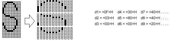
31 ESC *m nl nh [d1...dk] Select bit-image mode [Format] ASCII ESC * m nl nh[d1...dk] Hex 1B 2A m nl nh[d1...dk] Decimal m nl nh[d1...dk] [Range] m = 0, 1, 32, 33 0 nl nh 3 0 d 255 Selects bit-image mode using m for the number of dots specified by (nl+ nh,x256). This command is used to print a predefined picture or logo. The modes selectable by m are follows; m Mode Vertical Direction Horizontal Direction NO. of Dots Dot Density Dot Density Number of (Data(K) 0 8-dot single-density 8 60 DPI 90 DPI nl + nh x dot double-density 8 60 DPI 180 DPI nl + nh x dot single-density DPI 90 DPI (nl + nh x 256) x dot double-density DPI 180 DPI (nl + nh x 256) x 3 The nl and nh indicate the number of dots of the bit image in the horizontal direction. The number of dots is calculated by nl + nh x 256. If the bit-image data input exceeds the number of dots to be printed on a line, the excess data is ignored. d indicates the bit-image data. Set a corresponding bit of 1 to print a dot or to 0 to not print a dot. If the value of m is out of the specified range, nl and data following are processed as normal data. If the width of the printing area set by GS L and GS W less than the width required by the data sent with the ESC * command the following will be performed on the line in question (but the printing cannot exceed the maximum printable area) : 1 The width of the printing area is extended to the right to accommodate the amount of data. 2 If step 1 does not provide sufficient width for the data, the left margin is reduced to accommodate the data. For each bit of data in single-density mode, the printer prints two dots : for each bit of data in double-density mode, the printer prints one dot. Page31
, except upside-down mode. The relationship between the image data and the dots to be printed is as follows.")
32 This must be considered in calculating the amount of data that can be printed in one line. After printing a bit images the printer returns to normal data processing mode. This command is not affected by print modes (emphasized, double-strike, and underline etc.), except upside-down mode. The relationship between the image data and the dots to be printed is as follows. ESC - n Turn underline mode on/off [Format] ASCII ESC - n Hex 1B 2D n Decimal n [Range] 0 n 2, 48 n 50 Turns underline mode on or off, based on the following values of n. n Function 0, (48) Turns off underline mode 1, (49) Turns on underline mode (1-dot thick) 2, (50) Turns on underline mode (2-dots thick) The printer an underline all characters (including right-side character spacing), but cannot underline the space set by HT. The printer cannot underline 90 clockwise rotated characters and white/black inverted characters. When underline mode is turned off by setting the value of n to 0 or 48, the Page32
33 [Default] n = 0 [Reference] ESC! following data is not underlined, and the underline thickness set before the mode is turned off does not change. The default value thickness is 1 dot. Changing the character size does not affect the current underline thickness. Underline mode can also be turned on or off by using ESC!. Note, however, that the last received is effective. This command is not effective on Kanji characters. ESC 2 Select 1/6-inch line spacing [Format] ASCII ESC 2 Hex 1B 32 Decimal ESC 2 sets the line spacing to 1/6 of an inch. The line spacing can be set independently in standard mode and in page mode. [Reference] ESC 3 ESC 3 n Set line spacing [Format] ASCII ESC 3 n Hex 1B 33 n Decimal n [Range] 0 n 255 ESC 3 n sets the line spacing to [n x (vertical or horizontal motion unit)] inches. The default setting of the paper feed amount is 1/6 inch. The default value in the vertical direction is 1/144 inch. The line spacing can be set independently in standard mode and in page mode. Page33
34 The horizontal and vertical motion unit is specified by GS P. Changing the horizontal or vertical motion unit does not affect the current line spacing. The GS P command can change the horizontal (and vertical) motion unit. However, the value cannot be less than the minimum vertical movement amount, and it must be in even units of the minimum vertical movement amount. In standard mode, the vertical motions until (y) is used. This command function as follows in page mode, depending on the starting position of the printable area : When the starting position is set to the upper left or lower right to the printable area using ESC T, the vertical motion unit (y) is used. When the starting position is set to the upper right or lower left of the printable area using ESC T, the horizontal motion unit (x) is used. The maximum line spacing is 40 inches. When the setting value exceeds the maximum, it is converted to the maximum automatically. [Default] [Reference] Line space is equivalent to approximately 4.23mm(1/6inch) ESC 2, GS P ESC = n Set peripheral device [Format] ASCII ESC = n Hex 1B 3D n Decimal n [Range] 1 n 255 [Default] n=1 Selects device to which host computer sends data, using n as follows: Bit Off/On Hex Decimal Function 0 Off 00 0 Printer disabled On 01 1 Printer enabled Undefined When the printer is disabled, it ignores all data except for error-recovery commands (DLE EOT,DLE ENQ, DLE DC4) until it is enabled by this command. Page34
35 ESC? n Cancel user-defined characters [Format] ASCII ESC? n Hex 1B 3F n Decimal n [Range] 32 n 126 Cancels user-defined characters. This command cancels the pattern defined for the character code specified by n. After the user-defined characters is canceled, the corresponding pattern for the internal character is printed. This command deletes the pattern defined for the specified code in the font selected by ESC!. If a user-defined character has not been defined for the specified character code, the printer ignores this command. [Reference] ESC &, ESC % Initialize printer [Format] ASCII Hex 1B 40 Decimal is initializes the printer. The data in receive buffer is not cleared. Adjustment amount of the label starting position using GS A command is not cleared. ESC D [n1...nk] NUL Set horizontal tab positions [Format] ASCII ESC D n1 nk NUL Hex 1B 44 n1 nk 00 Decimal n1 nk 0 Page35
36 [Range] 1 n k 32 Set is horizontal tab positions. n specifies the column number for setting a horizontal tab position from the beginning of the line. k indicates the total number of horizontal tab positions to be set. The horizontal tab position is stored as a value of [character width x n] measured from the beginning of the line. The character width includes the right-side character spacing, and double-width characters are set with twice the width of normal characters. This command cancels the previous horizontal tab settings. When setting n = 8, the print position is moved to column 9 by sending HT. Up to 32 tab positions (k=32) can be set. Data exceeding 32-tab positions s is processed as normal data. Transmit [ n]k in ascending order and place a NUL code 0 at the end. When [n]k is less than or equal to the preceding value [n]k-1, tab setting is finished and the following data is processed as normal data, ESC D NUL cancels all horizontal tab positions. When [n]k exceeds the number of characters printable on one line, the tab position set is equal to the maximum printable column plus 1. The previously specified horizontal tab positions do not change. even if the character width changes. [Default] The default tab positions are at intervals of 8 characters (columns 9, 17, 25,...) for the font A (12 X 24). [Reference] HT ESC E n Turn emphasized mode on/off [Format] ASCII ESC E n Hex 1B 45 n Decimal n [Range] 0 n 255(Only the LSB of n is enabled.) Turns emphasized mode on or off. Only the lowest bit of n is valid. When n = <*******1>B, the emphasized characters are selected. When n = <*******0>B, the emphasized characters are canceled. Page36
![ESC! Also turns on and off emphasized mode. However, the last received command is effective. [Default] n = 0 [Reference] ESC!](/docs-images/91/107015891/images/37-0.jpg "ESC G n Select/cancel double-strike mode [Format] ASCII ESC G n Hex 1B 47 n Decimal 27 71 n [Range] 0 n 255 Select/cancel is double-strike mode. This command is available for all character types.")
37 ESC! Also turns on and off emphasized mode. However, the last received command is effective. [Default] n = 0 [Reference] ESC! ESC G n Select/cancel double-strike mode [Format] ASCII ESC G n Hex 1B 47 n Decimal n [Range] 0 n 255 Select/cancel is double-strike mode. This command is available for all character types. Only the lowest bit of n is valid. When n = <*******1>B, the double-strike mode is selected. When n = <*******0>B, the double-strike mode is canceled. In this printer, double- strike mode has the same function as emphasized mode. [Default] n = 0 [Reference] ESC E Page37
38 ESC J n Print and feed paper [Format] ASCII ESC J n Hex 1B 4A n Decimal n [Range] 0 n 255 ESC J n Prints the data in the print buffer and feeds the paper [n x (vertical or horizontal motion unit) inches. This command is used to temporarily feed a specific length without changing the line spacing set by other commands. After printing is completed, this command sets the print starting position to the beginning of the line. The paper feed amount set by this command does not affect the values set by ESC 2 or ESC 3. The horizontal and vertical motion unit is specified by GS P. The GS P command can change the vertical (and horizontal) motion unit. However, the value cannot be less than the minimum vertical movement, and it must be in even units of the minimum vertical movement amount. In standard mode, the printer uses the vertical motion unit. When this command is used in page mode, the command functions as follows, depending on the starting position of the printable area. When the starting position is set to the upper left or lower right of the printable area using ESC T, the vertical motion unit (y) is used. When the starting position is set to the upper right or lower left of the printable area using ESC T, the horizontal motion unit (x) is used. The maximum paper feed amount is 40 inches. Even if a paper feed amount of more than 40 inches is set, the printer feeds the paper only 40 inches. When label mode is selected and a paper feed amount that exceeds the length of one label is set, the printer feeds the label paper to the next print starting position. [Reference] GS P ESC L Page38
39 Select page mode [Format] ASCII ESC L Hex 1B 4C Decimal [Reference] Select from standard mode to page mode. This command is enabled only when input at the beginning of a line. This command has no affect in page mode. After printing by FF is completed or by using ESC S, the printer returns to standard mode. This command sets the position where data is buffered to the position specified by ESC T within the printing area defined by ESC W. This command is switches the setting for the following commands (in which the values can be set independently in standard mode and page mode) to those for page mode. 1 Set right-side character spacing: ESC SP 2 Select 1/6-inch line spacing: ESC 2 3 Set line spacing: ESC 3 Setting for the following commands are effective only in page mode: 1 Turn 90 clockwise rotation mode on/off: ESC V 2 Select justification: ESC a 3 Turn upside-down printing mode on/off: ESC { 4 Set left margin: GS L 5 Set printable area width: GS W The printer returns to standard mode by using the FF, CAN, ESC FF, ESC S, ESC T, ESC W, GS $, GS \ ESC M n Select character font [Format] ASCII ESC M n Hex 1B 4D n Decimal n [Range] n= 0, 1, 48, 49 Selects chatacter fonts n Function 0, (48) Character font A(12 X 24 ) Selected 1, (49) Character font B(9 X 24 ) Selected Page39
40 ESC R n Select international character set [Format] ASCII ESC R n Hex 1B 52 n Decimal n [Range] 0 n 13 ESC R n selects an international character set from the following table. n 0 U. S. A 1 France 2 Germany 3 U. K. 4 Denmark I 5 Sweden 6 Italy 7 Spain 8 Japan 9 Norway 10 Denmark II 11 Spain II 12 Latin America 13 Korea Character Set [Default] n = 0 [Reference] Character Code Tables ESC S Select standard mode [Format] ASCII ESC S Hex 1B 53 Decimal Select from page mode to standard mode. Page40
41 This command is effective only in page mode. Data buffered in page mode and the printable area developed in page mode are cleared. This command is switches the setting for the following command (in which the values can be set independently in standard mode and page mode) to those for standard mode: 1 Set right-side character spacing: ESC SP 2 Select 1/6-inch line spacing: ESC 2 3 Set line spacing: ESC 3 Setting for the following commands are effective only in standard mode: 1 Select print direction in page mode: ESC T 2 Set printing area in page mode: ESC W [Reference] FF, ESC FF, ESC L ESC T n Select print direction in page mode [Format] ASCII ESC T n Hex 1B 54 n Decimal n [Range] 0 n 3, 48 n 51 Select the print direction and starting position in page mode. n specifies the print direction and starting position as follows: N Print Direction Starting Position 0, (48) Left to right Upper left(a in the figure) 1, (49) Bottom to top Lower left(b in the figure) 2, (50) Right to left Lower right(c in the figure) 3, (51) Top to bottom Upper right(d in the figure) A D B Printing area C Paper feed direction Page41
42 When the command is input in standard mode, the printer executes only internal flag operation. This command does not affect printing in standard mode. This command sets yhe position where data is buffered within the printing area set by ESC W. Parameters for horizontal or vertical motion units (x or y) differ as follow, [Default] n = 0 depending on the starting position of the printing area: If the starting position is the upper left or lower right of the printing area, data is buffered in the direction perpendicular to the paper feed direction. Commands using horizontal motion units: ESC SP, ESC $, ESC \ Commands using vertical motion units: ESC 3, ESC J, GS $, GS \ If the starting position is the upper right or lower left of the printing area, data is buffered in the paper feed direction: Commands using horizontal motion units: ESC 3, ESC J, GS $, GS \ Commands using vertical motion units: ESC SP, ESC $, ESC \ [Reference] ESC $, ESC L, ESC W, GS $, GS P ESC V n Turn 90 clockwise rotation mode on/off [Format] ASCII ESC V n Hex 1B 56 n Decimal n [Range] 0 n 1,48 n 49 Turns 90 clockwise rotation mode on or off. When n = 1 or 49, 90 CW rotated characters are set. When n = 0 or 48, 90 CW rotated characters are canceled. When underline mode is turned on, the printer does not underline 90 clockwise-rotated characters. Double-width and double-height commands in 90 rotation mode enlarge characters in the opposite directions from double height and double-width commands in normal mode. This command is input in page mode, the printer performs only internal flag operations. [Default] n = 0 Page42
43 [Reference] ESC!, ESC - ESC W xl xh yl yh dxl dxh dyl dyh Set printing area in page mode [Format] ASCII ESC W xl xh yl yh dxl dxh dyl dyh Hex 1B 57 xl xh yl yh dxl dxh dyl dyh Decimal xl xh yl yh dxl dxh dyl dyh [Range] 0 xl xh yl yh dxl dxh dyl dyh 255 ESC W sets the position and size of the printing area. The horizontal starting position, vertical starting position, printing area width, and printing area height are defined as x0, y0, dx(inch),dy(inch), respectively. Each setting for the printable area is calculated as follow: x0 = [(xl + xh x 256) x (horizontal motion unit)] y0 = [(yl + yh x 256) x (vertical motion unit)] dx = [(dxl + dxh x 256) x (horizontal motion unit)] dy = [(dyl + dyh x 256) x (vertical motion unit)] If this command is input in standard mode, the printer executes printing in standard mode. If the horizontal or vertical starting position is set outside the printable area, the printer stops command processing and processes the following data as normal data. If the printing area width or height is set to 0, the printer stops command processing and processes the following data as normal data. This command sets the position where data is buffered to the position specified by ESC T within the printing area. If (horizontal starting position + printing area width) exceeds the printable area, the printing area width is a automatically set to (horizontal printable - horizontal starting position). If (vertical starting position + printing area height) exceeds the printable area, the printing area height is automatically set to( vertical printable area - vertical starting position). The horizontal and vertical motion units are specified by GS P. Changing the horizontal or vertical motion unit does not affect the current printing area. The GS P command can change the horizontal (and vertical) motion unit. However, the value cannot be less than the minimum horizontal movement amount, and it must be in even units of minimum horizontal movement amount. Page43
44 Use the horizontal motion unit for setting the horizontal starting position area width, and use the vertical motion unit for setting the vertical starting position and printing area height. When the horizontal starting position, vertical starting position, printing area width, and printing area height are defined as X,Y, Dx, and Dy respectively, the printing area is set as shown in the figure below. (0,0) Printable area of the paper (x,y) Dx Dy Printing area Forward (x + Dx -1, Y + Dy = 1) [Default] xl = xh = yl = yh = 0 dxl = 0, dxh = 2, dyl =126, dyh = 6 [Reference] CAN, ESC L, ESC T, GS P ESC \ nl nh Set relative print position [Format] ASCII ESC \ nl nh Hex 1B 5C nl nh Decimal nl nh [Range] 0 nl nh 255 Sets the print starting position based on the current position by using the horizontal or vertical motion unit. This command sets the distance from the current position to [(nl+ nh x 256) x (horizontal or vertical unit)]. When pitch n is specified to the right : nl + nh x 256 = n. When pitch n is specified to the left (the negative direction), use the complement of When pitch n is specified to the left : nl + nh x 256 = n. The print starting position moves from the current position to [n x (horizontal or vertical motion unit)]. Page44
45 The horizontal and vertical motion units are specified by GS P. The GS P command can change the horizontal (and vertical) motion unit. However, the value cannot be less than the minimum horizontal movement amount, and it must be in even units of the minimum horizontal movement amount. In standard mode, the horizontal motion unit is used. Any setting that exceeds the printable area is ignored. In page mode, the horizontal or vertical motion unit differs as follows, depending on the starting point of the printing area : When the starting position is set to the upper left or lower right of the printable area using ESC T, the horizontal motion unit (x) is used. When the starting position is set to the upper right or lower left of the printable area using ESC T, the vertical motion unit (y) is used. [Reference] ESC $, GS P ESC a n Select justification [Format] ASCII ESC a n Hex 1B 61 n Decimal n [Range] 0 n 2,48 n 50 ESC a n aligns all the data in one line to the specified position. ESC a n selects the type of justification as follows: n Justification 0,48 Left justification 1,49 Centering 2,50 Right justification The command is enabled only when input at the beginning of the line. If this command is input in page mode, the printer performs only internal flag operation. This command does not affect printing in page mode. Lines are justified within the specified printing area. Spaces set by HT, ESC $, and ESC \ are all justified. [Default] n = 0 [Example] Page45
46 Left justification Centering Right justification ABC ABCD ABCDE ABC ABCD ABCDE ABC ABCD ABCDE ESC c 3 n Select paper sensor(s) to output paper end signals [Format] ASCII ESC c 3 n Hex 1B n Decimal n [Range] 0 n 255 Selects the paper sensor(s) to output paper end signals. Bit Off / On Hex Decimal Function 0 Off 00 0 Paper roll near-end sensor disabled On 01 1 Paper roll near-end sensor enabled 1 Off 00 0 Paper roll near-end sensor disabled On 02 2 Paper roll near-end sensor enabled 2 Off 00 0 Paper roll end sensor disabled On 04 4 Paper roll end sensor enabled 3 Off 00 0 Paper roll end sensor disabled On 08 8 Paper roll end sensor enabled Undefined {Notes} It is possible to select multiple sensors to output signals. Then, if any of the sensors detects a paper end, the paper end signal is output. The command is available only with a parallel interface and is ignored with a serial interface. Sensor is switched when executing this command. The paper end signal switching be delayed depending on the receive buffer state. If either bit 0 or bit 1 is on, the paper roll near-end sensor is selected as the paper sensor outputting paper-end signals If either bit 2 or bit 3 is on, the paper roll end sensor is selected as the paper sensor outputting paper-end signals. When all the sensors are disabled, the paper end signal always outputs a paper present status. [Default] n = 15 Page46
Printer Control Command Set
 Printer Control Command Set Technical Manual Revision: November 1, 2017 Omniprint Inc. 1923 East Deere Ave., Santa Ana, California 92705, U.S.A. T: 949.833.0080 :: F: 949.833.0040 www.omniprintinc.com
ODP 200. Thermal Receipt Printer Technical Manual
 ODP 200 Thermal Receipt Printer Technical Manual TABLE OF CONTENTS 1. General Specifications 1.1 Printing Specifications 1.2 Character Specifications 1.3 Auto Cutter 1.4 Paper Roll Supply Device 1.5 Paper
PANDA Thermal Receipt Printer. Programmer Manual
 PANDA Thermal Receipt Printer Programmer Manual 1. COMMANDS 1.1 Command Notation The name of the command. [Format] The code sequence. [Range] Gives the allowable ranges for the arguments. Describes the
Command Manual SRP-350 Thermal Printer Rev. 1.01
 Command Manual SRP-350 Thermal Printer Rev. 1.01 http://www.samsungminiprinters.com 1. Control Commands List Control codes Hexadecimal codes Function 09 Horizontal tab 0A Print and line feed
MOBILE THERMAL PRINTER
 MOBILE THERMAL PRINTER MODEL CMP-30 series ESC Command Manual Rev. 1.00 TABLE OF CONTENTS 1. Command Description... 6 2. Commands... 7 HT... 7 LF... 7 CR... 8 FF... 8 CAN... 8 DLE EOT... 9 DLE ENQ... 12
Control Command list (ESC/POS)
") Printer Command Control Command list (ESC/POS) Rev 1.4 1. Command Summary 2. Control Command 3. [STAR Emulation Mode] Command Summary SAM4S PRINTER ELLIX30/40 1 Control Command list 1. Command Summary
Printer Command Control Command list (ESC/POS) Rev 1.4 1. Command Summary 2. Control Command 3. [STAR Emulation Mode] Command Summary SAM4S PRINTER ELLIX30/40 1 Control Command list 1. Command Summary
OM9500-II. Thermal Receipt printer Technical Manual. Revision: January 8, 2018
 OM9500-II Thermal Receipt printer Technical Manual Revision: January 8, Omniprint Inc. 1923 East Deere Ave., Santa Ana, California 92705, U.S.A. T: 949.833.0080 :: F: 949.833.0040 www.omniprintinc.com
MOBILE THERMAL PRINTER
 MOBILE THERMAL PRINTER MODEL CMP-20 series Technical Manual Rev. 1.00 TABLE OF CONTENTS 1. General Specifications 1.1 Printing Specifications 1.2 Character Specifications 1.3 Paper Specification 1.4 Printable
Tally Dascom DT-210/230 Programming Guide V1.1
 About This Manual Please read this technical manual before programming. Main description for command as below: 1) Function This is the first part of command description. Here we propose the command of
MODEL : TRP-100-II Receipt Printer User s Manual
 MODEL : TRP-100-II Receipt Printer User s Manual All specifications are subject to change without notice Table of Contents 1. Parts Identifications 3 2. Setting up the printer 4 2.1 Unpacking 4 2.2 Connecting
1. Control Command List
 1. Control Command List Num Control Code Function 01 HT Horizontal tab 02 LF Print and line feed 03 CR Print and carriage return 04 DLE EOT n Real-time status transmission 05 DLE ENQ n Real-time response
MODEL : PR-T25 Receipt Printer User s Manual
 MODEL : PR-T25 Receipt Printer User s Manual All specifications are subject to change without notice Table of Contents 1. Parts Identifications 1. Parts Identifications 3 2. Setting up the printer 4 2.1
MODEL : LK-T210 Receipt Printer User s Manual
 SEWOO TECH CO.,LTD. Doosung BD, 689-20, Geumjeong-dong, Gunpo-si, Gyeonggi-do, 435-862, Korea TEL : +82-31-459-8200 FAX : +82-31-459-8880 www.miniprinter.com MODEL : LK-T210 Receipt Printer User s Manual
MODEL : LK-T200 Receipt Printer User s Manual
 SEWOO TECH CO.,LTD. Doosung BD, 689-20, Geumjeong-dong, Gunpo-si, Gyeonggi-do, 435-862, Korea TEL : +82-31-459-8200 FAX : +82-31-459-8880 www.miniprinter.com MODEL : LK-T200 Receipt Printer User s Manual
Command Manual Metapace T-2. Thermal Printer Rev. 1.00
 Command Manual Metapace T-2 Thermal Printer Rev. 1.00 1. Control Commands List Command HT LF FF CR CAN DLE EOT DLE ENQ DLE DC4 ESC FF ESC SP ESC! ESC $ ESC % ESC & ESC * ESC - ESC 2 ESC 3 ESC = ESC? ESC
FEC-80T Receipt Printer User s Manual
 FEC-80T Receipt Printer User s Manual All specifications are subject to change without notice TABLE OF CONTENTS 1. Parts Identifications 3 2. Setting up the printer 4 2.1 Unpacking 4 2.2 Connecting the
4 Pr P i r n i t n e t r e Co C m o m m a m n a d n s d Li L s i t N. C m o m m a m n a d
 4. Printer Commands List NO. Command Function Description 01 HT Horizontal tab(#) 02 LF Print and line feed 03 CR Print and carriage return (#) 04 ESC SO Set all characters times width print 05 ESC DC4
TRP-100 Receipt Printer User s Manual
 TRP-100 Receipt Printer User s Manual All specifications are subject to change without notice TABLE OF CONTENTS 1. Parts Identifications 3 2. Setting up the printer 4 2.1 Unpacking 4 2.2 Connecting the
WinPOS system. Co., ltd. WP-K837 series. Esc/POS Command specifications Ver.0.94
 WinPOS system. Co., ltd. WP-K837 series Esc/POS Command specifications 2014-05-06 Ver.0.94 LF Prints buffered data and feeds one line. Syntax: ASCII LF Hex 0A Decimal 10 Remarks: This command sets the
DS-800. ::: Receipt Printer User s manual :::
 DS-800 ::: Receipt Printer User s manual ::: All specifications are subjected to change without notice TABLE OF CONTENTS 1. Parts Identifications 2 2. Setting up the printer 3 2.1 Unpacking 3 2.2 Connecting
MODEL : AP-8220 U Receipt Printer User s Manual
 MODEL : AP-8220 U Receipt Printer User s Manual AP-8220 U Rev.A 10/14 All specifications are subject to change without notice Table of Contents 1. Parts Identifications 1. Parts Identifications 3 2. Setting
PROGRAMMER S MANUAL 58mm Printer
 PROGRAMMER S MANUAL 58mm Printer (#)Note: this command is available for POS58 model. 5. Printer Commands List 5.1 Command Conception POS58 series printers support ESC/POS print commands. Descriptions as
[Notes] Provides important information on setting and using the printer command, if necessary.
![[Notes] Provides important information on setting and using the printer command, if necessary.](/thumbs/95/122526477.jpg "[Notes] Provides important information on setting and using the printer command, if necessary.") 2. COMMANDS 2. 1 Command Notation X X X X [Name] The name of the command. [Format] The code sequence. [Range] Gives the allowable ranges for the arguments. [Description] Describes the command s function.
2. COMMANDS 2. 1 Command Notation X X X X [Name] The name of the command. [Format] The code sequence. [Range] Gives the allowable ranges for the arguments. [Description] Describes the command s function.
MODEL : TRP100-III Receipt Printer User s Manual
 MODEL : TRP100-III Receipt Printer User s Manual All specifications are subject to change without notice A software tool is available to configure the printer settings on AURES technical website: www.aures-support.fr
MODEL : SLK-TE20X Series Receipt Printer User s Manual
 MODEL : SLK-TE20X Series Receipt Printer User s Manual TE20X Series Rev.F 03/16 All specifications are subject to change without notice Table of Contents 1. Parts Identifications 1. Parts Identifications
MODEL : SLK-T12EB Receipt Printer User s Manual
 J. STEPHEN Lab., Ltd. 28-6, Gajangsaneopdong-ro, Osan-si, Gyeonggi-do, 447-210 Republic of Korea TEL : +82-31-8077-5000 FAX : +82-31-459-8880 www.miniprinter.com MODEL : SLK-T12EB Receipt Printer User
MODEL : LK-TL200 Receipt Printer User s Manual
 SEWOO TECH CO.,LTD. 28-6, Gajangsaneopdong-ro, Osan-si, Gyeongi-do, 447-210, Korea TEL : +82-31-459-8200 FAX : +82-31-459-8880 www.miniprinter.com MODEL : LK-TL200 Receipt Printer User s Manual TL200 Rev.
Command Manual SPP-R200. Mobile Printer Rev
 Command Manual SPP-R200 Mobile Printer Rev. 1.03 http://www.bixolon.com Table of Contents 1. Notice... 3 2. Control Commands List... 3 3. Control Commands Details... 5 3-1 Command Notation... 5 3-2 Explanation
MODEL : SLK-TL100 Receipt Printer User s Manual
 J. STEPHEN Lab., Ltd. 28-6, Gajangsaneopdong-ro, Osan-si, Gyeongi-do, 447-210, Korea TEL : +82-31-459-8200 FAX : +82-31-459-8880 www.miniprinter.com MODEL : SLK-TL100 Receipt Printer User s Manual TL100
PP7X PRINTER COMMAND MANUAL
 PP7X PRINTER COMMAND MANUAL Pinnacle Technology Corp. CONTENTS 1 COMMANDS... 1 2 COMMAND SAMPLE (hex command)... 31 1 COMMANDS The command explanations include the following parts: 1 Name and the general
PP7X PRINTER COMMAND MANUAL
 PP7X PRINTER COMMAND MANUAL Pinnacle Technology Corp. CONTENTS 1 COMMANDS... 1 2 COMMAND SAMPLE (hex command)... 30 1 COMMANDS The command explanations include the following parts: 1) Name and the general
SRP-330 Command Manual Rev. 1.01
 Command Manual Rev. 1.01 http://www.bixolon.com Contents 1. Notice... 3 2. Control Commands List in Alphanumeric Order... 4 2-1 Command Description Items... 6 2-2 Details of Control Commands... 7 Rev.
STP-103II Thermal Printer Command Manual
 Thermal Printer Command Manual Contents 1. Notice... 3 2. Control Commands List in Alphanumeric Order... 4 2-1 Command Description Items... 6 2-2 Details of Control Commands... 7 Rev. 1.02 BIXOLON - 2
MODEL : SLK-TS400EB. Receipt Printer User s Manual. TS400EB Rev. B 07/16. All specifications are subject to change without notice
 MODEL : SLK-TS400EB Receipt Printer User s Manual TS400EB Rev. B 07/16 All specifications are subject to change without notice Table of Contents 1. Parts Identifications 1. Parts Identifications 3 2.
SPP-R300 Command Manual Rev. 1.01
 Rev. 1.01 http://www.bixolon.com Contents 1. Notice... 3 2. SPP-R300 Supported Commands... 4 2-1 Command Description Items... 5 2-2 Details of Control Commands... 6 Rev. 1.01 BIXOLON - 2 - 1. Notice This
SRP-275III Command Manual Rev. 1.00
 Rev. 1.00 http://www.bixolon.com Contents 1. Notice... 3 2. SRP-275III Supported Commands... 4 2-1 Command Description Items... 5 2-2 Details of Control Commands... 6 Rev. 1.00 BIXOLON - 2 - 1. Notice
Command Emulator ESC/POS Mode Command Specifications
 Line Thermal Printer ESC/POS Mode Command Specifications Revision 1.02 Star Micronics Co., Ltd. Special Products Operating Division TABLE OF CONTENTS 1....1-1 1-1) Command List... 1-1 1-2) COMMAND DETAILS...
POS Thermal Receipt Printer A11 Standard/Prime
 A11-Prime/Standard-E(Rev001) POS Thermal Receipt Printer A11 Standard/Prime Command Manual Table of Contents 1. Notice... 3 2. Control Commands List in Alphanumeric Order... 4 2-1 Command Description Items...
SRP-QE300/302 Command Manual Rev
 Command Manual Rev. 1.00 http://www.bixolon.com Contents SRP-QE300/302 1. Notice... 3 2. Control Commands List in Alphanumeric Order... 4 2-1 Command Description Items... 6 2-2 Details of Control Commands...
PP8X Printer Command Manual
 PP8X Printer Command Manual Pinnacle Technology Corp. CONTENTS 1 COMMANDS... 1 2 COMMAND SAMPLE (hex command)... 29 1 COMMANDS Command Decimal Hex Function HT 9 9 Horizontal tab LF 10 0A Print and line
PP8X Printer Command Manual
 PP8X Printer Command Manual Pinnacle Technology Corp. CONTENTS 1 COMMANDS... 1 2 COMMAND SAMPLE (hex command)... 29 1 COMMANDS Command Decimal Hex Function HT 9 9 Horizontal tab LF 10 0A Print and line
Receipt Printer BTP-R580II. Programming Manual. Shandong New Beiyang Information Technology Co., Ltd.
 Receipt Printer BTP-R580II Programming Manual Shandong New Beiyang Information Technology Co., Ltd. REVISION HISTORY Date Version Description Author 2011-9-6 V100 Initial draft Sun Chuanliang - 1 - Declaration
SRP-F310/312 Command Manual Rev. 1.00
 Command Manual Rev. 1.00 http://www.bixolon.com Contents 1. Notice...3 2. Control Commands List in Alphanumeric Order...4 2-1 Command Description Items...6 2-2 Details of Control Commands...7 Rev. 1.00
Command Manual SPP-R200. Mobile Printer Rev
 Command Manual SPP-R200 Mobile Printer Rev. 0.10 http://www.samsungminiprinters.com 1. Control Commands List COMMAND Name Funtion type 1 LF Print and line feed Print 2 FF Print and return to standard mode
MODEL 814M DIRECT THERMAL PRINTER PROGRAMMING MANUAL
 MODEL 814M DIRECT THERMAL PRINTER PROGRAMMING MANUAL PART NUMBER 880048-0101 Revised 04/14 MSG Copyright 2014 by Microcom Corporation, Lewis Center, Ohio All rights reserved. Printed in the United States
COMMAND REFERENCE COMMAND REFERENCE PLUS II
 COMMAND REFERENCE PLUS II Edit by: CUSTOM ENGINEERING S.p.A. Str. Berettine 2-43010 Fontevivo (PARMA) - Italy http: www.custom.biz All rights reserved 2 Command Reference Introduction 1 INTRODUCTION 1.1
SPP-R210 Command Manual Rev. 1.00
 Rev. 1.00 http://www.bixolon.com Contents SPP-R210 Command Manual 1. Notice... 3 2. SPP-R210 Supported Commands... 4 2-1 Command Description Items... 5 2-2 Details of Control Commands... 6 Rev. 1.00 BIXOLON
NEO-PLACA-PRINTER-PT486F24401
 PT486F24401 Control board specifications NEO-PLACA-PRINTER-PT486F24401 Add: 4/5F, 8#, Gaoqi Nan Shi er Road, (AideAirport Industrial Park) Xiamen, Fujian, China-361006. Tel: +86-592-5932525 +86-592-5235252
XR-200 MINI DOT IMPACT PRINTER PRODUCT SPECIFICATION DATE : MAY 3, 2004 MANUAL REVISION 2.0
 XR-200 MINI DOT IMPACT PRINTER PRODUCT SPECIFICATI DATE : MAY 3, 2004 MANUAL REVISI 2.0 Features Dip Switch Configuration Emulation mode, communications mode, baud rate, serial/parallel handshake, and
SRP-275II Impact Printer Command Manual
 SRP-275II Impact Printer Command Manual Contents 1. Notice...3 2. SRP-275II Supported Commands...4 2-1 Command Description Items...5 2-2 Details of Control Commands...6 Rev. 1.00 BIXOLON - 2 - 1. Notice
One station Impact Printer. Model: WP-300 Version : 1.03
 One station Impact Printer Model: WP-300 Version : 1.03 INDEX 1. GENERAL SPECIFICATION... 2 1.1 DESCRIPTION... 2 1.2 CHARACTERISTICS... 2 1.3 ACCESSORIES... 2 2. MAIN SPECIFICATION... 3 3. ILLUSTRATION...
Mobile Printer. Command Manual Ver Models: SM series
 Mobile Printer Command Manual Ver. 1.9 Models: SM series CONTENTS 1. Printer Control Function...3 1.1. Print Commands...5 1.2. Line Spacing Commands....7 1.3. Character Commands...8 1.4. Print Position
VKP80 VKP80II VKP80II-EE STATUS LINE FEED. RS232 ETHERNET USB Vin FORM FEED
 STATUS COMMAND REFERENCE VKP80 VKP80II LINE FEED FORM FEED RS232 ETHERNET USB Vin VKP80II-EE Edit by: CUSTOM ENGINEERING S.p.A. Str. Berettine 2-43010 Fontevivo (PARMA) - Italy http: www.custom.biz All
TSP552 TSP552II TSP2000
 THERMAL PRINTER TSP552 TSP552II TSP2000 PROGRAMMER'S MANUAL Trademark acknowledgments TSP552, TSP552II, TSP2000: Star Micronics Co., Ltd. ESC/POS: Seiko Epson Corporation Notice All rights reserved. Reproduction
KM216H KPM216H WARNING! MOVING PARTS PUSH HERE TO CLOSE
 WARNING! COMMAND REFERENCE KM216H PUSH HERE TO CLOSE MOVING PARTS KPM216H Edit by: CUSTOM ENGINEERING S.p.A. Str. Berettine 2-43010 Fontevivo (PARMA) - Italy http: www.custom.biz All rights reserved 2
SRP RECEIPT PRINTER. Operator s Manual. All specifications are subjected to change without notice
 SRP - 350 RECEIPT PRINTER Operator s Manual All specifications are subjected to change without notice Warning - U.S. This equipment has been tested and found to comply with the limits for a Class A digital
Command Manual.
 Command Manual http://www.woosim.com CONTENTS 1. Printer Control Function...3 1.1. Print Commands....5 1.2. Line Spacing Commands....8 1.3. Character Commands....9 1.4. Print Position Commands.... 19 1.5.
TM-L60II/L60IIP. The words on the left side of this screen are bookmarks for all the topics in this guide.
 TM-L60II/L60IIP Using this online information guide The words on the left side of this screen are bookmarks for all the topics in this guide. Use the scroll bar next to the bookmarks to find any topic
DIR-E58III Mobile Print
 1 Kunxilin Electronic Co.,LTD Kunxi HK Electronic Technology Limited Web: http://www.siipos.com http://www.sii-prt.com WhatsApp:13632856413 SKYPE:kunxisz QQ:2676804008 DIR-E58III Mobile Print Development
MP200 DOT MATRIX IMPACT PRINTER USER MANUAL
 MP200 DOT MATRIX IMPACT PRINTER USER MANUAL All specifications are subject to change without notice Disposal of Old Electrical & Electronic Equipment (Applicable in the European Union and other European
MODEL : SLK-D10 Mini Dot Impact Printer
 MODEL : SLK-D10 Mini Dot Impact Printer All specifications are subject to change without notice 1 Table of Contents 1. Features 3 2. Specification 4 3. Self Test 6 4. Configuration Setup 7 5. User Switches
REVISION RECORDS REV. DATE DESCRIPTION DRAWN CHECKED APPROVED
 User Manual MPT725 Xiamen PRT Technology Co.,Ltd. ADD: 4/5F, 8#, Gaoqi Nan Shi er Road, (AideAirport Industrial Park) Xiamen, Fujian, China-361006. Tel.: +86-(0)592-5932525 Fax: +86-(0)592-5235252 Web:
Thermal Bluetooth Printer
 Thermal Bluetooth Printer ---Version 1.0.0.4 Introduction Appreciate for purchasing our thermal receipt series printers. This manual is used on our mini portable thermal receipt series printers which include
628/638_ Specification
 628/638_110105 Specification Date Version Remark Jan. 5, 2011 V2.0 Contents 1.Introduction... 1 2. Appearance and PIN definition... 1 2.1 Appearance... 1 2.2 J3 RS232... 1 2.3 J2 TTL... 1 3 specifications...
SPRT. Portable Micro Printer
 R -TⅢ Portable Micro Printer User s Manual Beijing Spirit Technology Development Co, Ltd. www.sprinter.com.cn Content Operating Precautions 3 Notes on Safety 3 Notes on Using 3 Notes on Handling 4 Chapter
MPP6800 series - PANEL MOUNT PRINTERS. Options
 series - PANEL MOUNT PRINTERS Page 1 of 12 MPP6810 MPP6820 MPP6840 Introduction 5-8Vdc, 4A peak 5-8Vdc, 2A peak 10-35Vdc 24Vdc Features Easy load paper feature High resolution thermal printing 5-8Vdc standard,
MODEL WSP-i350. (3inch Industrial Printer)
") MODEL WSP-i350 (3inch Industrial Printer) WOOSIM SYSTEMS Inc. #501, Daerung Technotown 3th, 448, Gasan-Dong, GeumChun-Ku, Seoul, Korea Tel : +82-2-2107-3700 Fax : +82-2-2107-3707 URL: http://www.woosim.com
MODEL WSP-i350 (3inch Industrial Printer) WOOSIM SYSTEMS Inc. #501, Daerung Technotown 3th, 448, Gasan-Dong, GeumChun-Ku, Seoul, Korea Tel : +82-2-2107-3700 Fax : +82-2-2107-3707 URL: http://www.woosim.com
TM200 USER S MANUAL USER S MANUAL. for THERMAL RECEIPT PRINTER
 USER S MANUAL for THERMAL RECEIPT PRINTER TM200 USER S MANUAL This is a general guide for TM200 direct thermal printer, and not all functions will perform in every printer. Other than specified in this
Mobile POS Thermal printer
 PK109 Mobile POS Thermal printer MEGADATA INDUSTRIAL, Inc. 1F, NO.10, Lane 58, Ta Chuan Street, TAICHUNG, TAIWAN R.O.C. TEL: +886-4-2376-6881 FAX: +886-4-2371-7974 www.posjet.com.tw megadata@ms21.hinet.net
Reliance-ESC/POS Documentation
 Reliance-ESC/POS Documentation Release 1.0.2 Pyramid Technologies Jun 25, 2018 Contents 1 Command Table Layout 3 2 Pseudo Command Syntax 7 3 Printer Information 9 4 Font Controlling Commands 13 5 Cursor
Dot Matrix Printer. SP2000 Series. Programmer s Manual
 Dot Matrix Printer SP2000 Series Programmer s Manual TABLE OF CONTENTS 1. Control Codes (Star Mode)... 1 1-1. Control Codes List... 1 1-1-1. Character Selection... 1 1-1-2. Print Position Control... 3
COMBINATION PRINTER SCP700 SERIES
 COMBINATION PRINTER SCP700 SERIES Programmer s Manual Trademark acknowledgments SCP700: Star Micronics Co. Ltd. ESC/POS, TM-295, TM-T85: Seiko Epson Corporation Notice All rights reserved. Reproduction
The ICP 300 is an ultra-compact, lightweight portable thermal printer with an easy-load paper feature.
 THERMAL PRINTER Applications Datasheet Features Easy-Load paper feature RS232 Interface 10-35VDC Power Supply requirement High speed, high resolution printing capability Quiet, non-impact system Maintenance-free
KPM202 KPM203 KPM302 KPM303 TK202 TK203 TK302 TK303
 OEM COMMANDS MANUAL KPM202 KPM203 KPM302 KPM303 TK202 TK203 TK302 TK303 Code: 77200000030600 CUSTOM ENGINEERING S.p.A. Str. Berettine 2 43010 Fontevivo (PARMA) - Italy Tel. : +39 0521-680111 Fax : +39
SPRT SP-POS88III Line Thermal Printer
 SP-POS88III Line Thermal Printer User s Manual Beijing Spirit Technology Development Co, Ltd. Content troduction 2 Chapter 1 Feature and Performance 3 1.1 Print Performance 3 1.2 Print Paper 3 1.3 Print
TM-U295/U295P. Using this online operator s guide. Operator s Manual
 TM-U295/U295P Operator s Manual Using this online operator s guide The words on the left side of this screen are bookmarks for all the topics in this guide. Use the scroll bar next to the bookmarks to
PRODUCT INFORMATION. MPP5500 Series PANEL-MOUNT PRINTERS
 PRODUCT INFORMATION Series PANEL-MOUNT PRINTERS Applications Datasheet Features Easy load paper feature High speed, high resolution printing 5Vdc, 10-35Vdc or low power Quiet, non-impact system Maintenance-free
Dot Matrix Printer. SP300 Series. Programmer s Manual
 Dot Matrix Printer SP300 Series Programmer s Manual TABLE OF CONTENTS 1. CONTROL PANEL... 1 1-1. Basic Operation... 1 1-2. Switch Operation (Combined Switch Operation)... 2 2. SERIAL INTERFACE... 7 2-1.
Manopla para abertura da impressora
 MANUAL ESCRIBA 80 CARACTERÍSTICAS Mecanismo de Impressão Térmica Alimentação 24V Comunicação USB e Serial (RS232) Duas posições para a bobina de papel Botão de tracionamento do papel Driver para Windows
 )$4 DERXW (6& 326 [Format] [Range] [Default] [Description] The name of the command. The code sequence. [ ]k indicates the contents of the [ ] should be repeated k times. Gives the allowable ranges,
Customer Pole Display. Model: WD-304 Version: 1.12
 Customer Pole Display Model: WD-304 Version: 1.12 INDEX 1 FEATURES... 3 2 GENERAL SPECIFICATIONS... 4 3 UNPACKING... 5 3.1 PARTS LIST (WITH BASE PCB)... 5 3.2 PARTS LIST (WITHOUT BASE PCB)... 6 4 CONFIGURATION...
MTP-1500 Modular Thermal Printer. User Manual
 MTP-1500 Modular Thermal Printer User Manual TELPAR A Platinum Equity COMPANY 187 Crosby Road Dover, New Hampshire 03820 Toll Free: 800-872-4886 (from the U.S.A. and Canada only) 603-750-7237 Fax: 603-742-9938
Thermal printer for information kiosks and ATMs VKP80. User Manual. VKP80
 Thermal printer for information kiosks and ATMs User Manual www.custom.it All rights reserved. Total or partial reproduction of this manual in whatever form, whether by printed or electronic means, is
FEC-240G. Rev. Date
 Model User s Manual Contents Contents. 1 Features... 2 Type Model and Serial Number... 2 Specifications... 3 Interface Connections...... 4 DIP Switch Setting... 6 Dimension... 7 Command Set Table... 8
Command Specifications Rev 0.01
 Line Thermal Printer STAR Line Mode Command Specifications Rev 0.01 Table of Contents 1. INTERFACE CONFIGURATION... 1-1 1-1) RS-232C Serial Interface... 1-1 1-1-1) Specifications (Conforming to RS-232)...
Command Specifications Rev 0.09
 Line Thermal Printer STAR Line Mode Command Specifications Rev 0.09 Star Micronics Co., Ltd. Special Products Division Table of Contents 1. INTERFACE CONFIGURATION...1-1 1.1. RS-232 Serial Interface...1-1
ZQ110. Mobile Printer Command Manual. P Rev. A
 Mobile Printer Command Manual P1069085-001 Rev. A Table of Contents 1. Notice... 6 2. Control Commands List... 6 3. Control Commands Details... 8 3-1 Command Notation... 8 3-2 Explanation of Terms... 8
Command Specifications Rev 1.90
 Line Thermal Printer StarPRNT Command Specifications Rev 1.90 Star Micronics Co., Ltd. Special Products Division Table of Contents 1. COMMAND FUNCTION LIST... 1-1 2. COMMAND DETAILS... 2-1 2.1. Explanation
User s Manual AOPOS T220III THERMAL RECEIPT PRINTER. AOPOS SYSTEMS, S.A.
 User s Manual WARNING: All rights reserved. No part of this publication may be reproduced, stored in a retrieval, or transmitted in any form or by any means, electronic, mechanical, photocopying, recording,
Thermal printer for information kiosks and ATMs KPM 216 H. 210/216mm (8.5 ) User Manual. KPM216H
 User Manual. KPM216H") Thermal printer for information kiosks and ATMs KPM 216 H 210/216mm (8.5 ) User Manual www.custom.it All rights reserved. Total or partial reproduction of this manual in whatever form, whether by printed
Thermal printer for information kiosks and ATMs KPM 216 H 210/216mm (8.5 ) User Manual www.custom.it All rights reserved. Total or partial reproduction of this manual in whatever form, whether by printed
User s Manual. PDF created with pdffactory Pro trial version
 POS76Ⅱ Printer User s Manual Content Part 1 Performance Index 2 Part 2 Operation Specifications 5 2.1 Printer Appearance 5 2.2 Interface Connection 5 2.2.1 Serial Interface 5 2.2.2 Parallel Interface 6
ADDMASTER. Addmaster Corporation. IJ-3080 Journal/Validation Printer. Specification. IJ-3080 Specification
 IJ-3080 Journal/Validation Printer Specification Provides the electrical, mechanical, and interface specifications of the IJ-3080 Journal/Validation Printer. Cover Models: IJ-3080 The Addmaster Model IJ-3080
OKIPOS 408II. Programmer s Technical Reference. Section 1: Star Line Mode Page 3 Section 2: Star Page Mode Page 229 *
 OKIPOS 408II Programmer s Technical Reference Section 1: Star Line Mode Page 3 Section 2: Star Page Mode Page 229 * *(note that page numbers restart in Section 2) 59102801 Table of Contents 1. INTERFACE
PRINTER PRESENTER UNIT Command Reference. Model: PPU-700/700II. Revision: /03/26
 PRINTER PRESENTER UNIT Command Reference Model: PPU-700/700II Revision: 1.11 2010/03/26 REVISION Rev No. Date Comment 0.00 2004/01/14 Newly issued 1.00 2005/03/4 1.02 2005/04/25 Change of code pages GS
Addmaster Corporation
 IJ-1000 Ink-Jet Validation Printer Specification Addmaster Corporation Address: 225 East Huntington Drive Monrovia, CA 91016 Web: www.addmaster.com Phone: (626) 358-2395 FAX: (626) 358-2784 Document: ij1w.doc
PRINTER READY 28/04/08 11:03:50 TK300II KPM300 KUBE II KUBE-L
 PRINTER READY 28/04/08 11:03:50 COMMAND REFERENCE TK300II KPM300 KUBE II KUBE-L Edit by: CUSTOM ENGINEERING S.p.A. Str. Berettine 2-43010 Fontevivo (PARMA) - Italy http: www.custom.biz All rights reserved
COMMANDS MANUAL TG2460H TG2480H TL60 TL80
 COMMANDS MANUAL TG2480H TL80 CUSTOM S.p.A. Via Berettine 2/B 43010 Fontevivo (PARMA) - Italy Tel. : +39 0521-680111 Fax : +39 0521-610701 http: www.custom.biz Customer Service Department: Email : support@custom.it
User s Manual Models CD5220 / CD6220. Vacuum Fluorescent Customer Display
 User s Manual Models CD5220 / CD6220 Vacuum Fluorescent Customer Display INDEX 1. FEATURES...3 2. TYPE CLASSIFICATION...4 3. GENERAL SPECIFICATIONS...5 4. INTERFACE SPECIFICATIONS...6 5. FUNCTION SELECTION...9
VKP80 VKP80II USER MANUAL
 VKP80 II USER MANUAL OEM All rights reserved. Total or partial reproduction of this manual in whatever form, whether by printed or electronic means, is forbidden. While guaranteeing that the information
Command Specifications Rev. 2.13
 Line Thermal Printer StarPRNT Command Specifications Rev. 2.13 Star Micronics Co., Ltd. Special Products Division Table of Contents 1. COMMAND FUNCTION LIST... 1-1 2. COMMAND DETAILS... 2-1 2.1. Explanation