AOI for MGB-L1B-EI on Allen Bradley ControlLogix
|
|
|
- Alexia Morgan
- 6 years ago
- Views:
Transcription

1 AOI for MGB-L1B-EI on Allen Bradley ControlLogix Contents Guard locking according to EN ISO spring force to lock, power to release (closed-circuit current principle)... 2 Components/modules used... 2 EUCHNER... 2 Others... 2 Software... 2 Functional description... 3 General... 3 Data structure... 3 Mounting... 3 Installing the EDS file... 3 Setting up the EUCHNER MGB with Ethernet/IP... 3 Using the EUCHNER AOI Importing the AOI Adding the AOI_MGB command in the safety program Creating the control tag for the AOI_MGB command Linking the AOI_MGB command to the MGB Creating the tags for the safety task Creating the output tag for the standard task Data structures produced due to the AOI Important note please observe carefully! AP /16 Page 1 of 14

2 Guard locking according to EN ISO spring force to lock, power to release (closed-circuit current principle) Safety function Guard locking for personnel protection according to EN ISO Reliability figures according to EN ISO Category 4, PL e Components/modules used EUCHNER Description Safety system MGB with Ethernet/IP interface, guard locking with guard lock monitoring Order no./item designation Set / MGB-L1HB-EIA-R / MGB-L1HB-EIA-L Order no./item designation Evaluation unit / MGB-L1B-EIA-R / MGB-L1B-EIA-L Tip: More information and downloads about the aforementioned EUCHNER products can be found at www. EUCHNER.com. Simply enter the order number in the search box. Others Description Allen Bradley ControlLogix 4 Slots Chassis Allen Bradley Logix 5576S Automation Controller 8M/4M Allen Bradley Logix L7SP SIL3 PLe Safety Partner Item Mat No PN Mat No PN Mat No PN Allen Bradley 2-PORT CLX HI-CAP ENET/IP MODULE TP Mat No Notice: The device can be operated on control systems of the type RSLogix5000 from version 20. (Firmware ). Software Figure 1 AP /16 Page 2 of 14

3 Functional description General The MGB-L1B-EI is guard locking in accordance with EN ISO according to the closed-circuit current principle. In this example all safety functions are processed via the CIP Safety protocol. The MGB is connected to an Allen Bradley ControlLogix CPU. Figure 2 Data structure Figure 2 shows the general data structure. For the respective MGB selected, only the bits described in the related data sheet are used. For example, on an MGB without connection for an enabling switch, bit FI.EN is always 0. A description of the individual bits of the data structure is given in the operating instructions. Important: In the MGB Ethernet/IP all data are only transmitted via CIP Safety in the safety area. This does not mean the data all have a PL or SIL in safety-related terms. Only the data that start with FI or FO are subject to safety-related assessment. This application is based on the operating instructions for the MGB-L..B-EI- (Ethernet/IP) with data structure type A. The technical details are available in the operating instructions. Tip: The operating instructions are available at Simply enter the order number for the device in the search box. Mounting Please ensure the device is mounted correctly as described in the operating instructions. Installing the EDS file The EDS file is saved in the MGB and can be downloaded. The EDS file does not contain any information on the operation of the MGB. Setting up the EUCHNER MGB with Ethernet/IP Setup via a "Generic Safety Device" is described in application Use this application before you install the AOI. AP /16 Page 3 of 14
.")

4 Using the EUCHNER AOI An Add-On-Instruction (AOI) is available from Euchner in the internet at "Service Downloads Software". Prior to use, download the file AOI_MGB_Vx.xx.L5X (x.xx stands for the version of the AOI). On the usage of the new command AOI_MGB, the safe information is separated from the standard information and the identifiers for the individual bits from the related MGB assigned. The command must be used for each MGB that is used in the system. 1. Importing the AOI Go offline with Studio5000. Right-click the Add-On Instructions folder in the Controller Organizer window to obtain the following screen. Figure 3 Now import the new AOI from the folder in which you have saved the downloaded file. Studio5000 now imports all the necessary information and displays it. Please accept using OK. Figure 4 AP /16 Page 4 of 14


5 After the import you will see the new AOI_MGB command in the Add-On Instructions folder as well as the new data types for the MGB in the Data Types folder, User-Defined sub-folder Figure 5 2. Adding the AOI_MGB command in the safety program Now prepare a new rung on the ladder diagram in the safety task Figure 6 AP /16 Page 5 of 14

.")
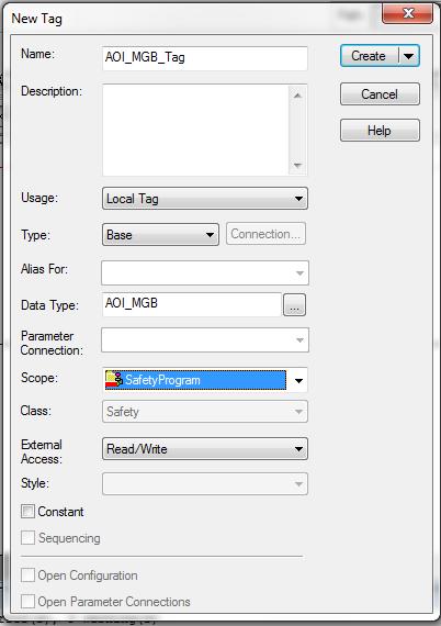
6 Figure 7 Figure 8 3. Creating the control tag for the AOI_MGB command The tag for the command must be created (for example using right mouse button and "New Tag"). AP /16 Page 6 of 14

7 Figure 9 Figure 10 AP /16 Page 7 of 14


8 4. Linking the AOI_MGB command to the MGB Once the tag has been created, the inputs and outputs on the MGB used must be linked in the MGB_Device_Input_Data field and in the MGB_Device_Output_Data field. For this purpose select the identifier for the MGB to which the command is to be linked (here the identifier from the application AP ) Figure 11 Figure 12 AP /16 Page 8 of 14


9 5. Creating the tags for the safety task Create a new tag for the standard program as well as a new tag for the safety program. Figure 13 Figure 14 AP /16 Page 9 of 14

10 Now create the standard tags for input and output. Figure 15 Figure 16 AP /16 Page 10 of 14


11 Then check whether the command has been added correctly to the rung. If an error has occurred, please correct it. Figure Creating the output tag for the standard task In the global controller tags create a new standard tag; this tag will contain the output bits that are to be used in the standard task. ATTENTION: The new variable must be created in the class Standard! Figure 18 During processing in the safety task, the AOI_MGB command copies the necessary bits from the MGB input area to the variables created earlier. The outputs from the standard task are copied to the MGB structure. To separate safe bits and standard bits, the standard bits for the outputs still need to be made available on the standard tasks. For this purpose the corresponding part of the safety bits is mapped to the new variable just created. The safe inputs can be read directly from the safe data in the standard task. Figure 19 AP /16 Page 11 of 14


12 Figure Data structures produced due to the AOI The following bits are now available in the safe task. Figure 21 AP /16 Page 12 of 14


13 The following bits are available as read-only data in the standard task. Figure 22 The following bits are available as data that can be written in the standard task. Figure 23 AP /16 Page 13 of 14
14 Important note please observe carefully! This document is intended for a design engineer who possesses the requisite knowledge in safety engineering and knows the applicable standards, e.g. through training for qualification as a safety engineer. Only with the appropriate qualification is it possible to integrate the introduced example into a complete safety chain. The example represents only part of a complete safety chain and does not fulfill any safety function on its own. In order to fulfill a safety function, the energy switch-off function for the hazard location and the software within the safety evaluation must also be considered, for example. The introduced applications are only examples for solving certain safety tasks for protecting safety doors. The examples cannot be comprehensive due to the application-dependent and individual protection goals within a machine/installation. If questions concerning this example remain open, please contact us directly. In accordance with Machinery Directive 2006/42/EC, the design engineer of a machine or installation is obligated to perform a risk assessment and take measures to reduce the risk. When doing this, the engineer must comply with the applicable national and international standards. Standards generally represent the current state of the art. Therefore, the design engineer should continuously inform himself about changes in the standards and adapt his considerations to them. Relevant standards include EN ISO and EN This application must be regarded only as assistance for the considerations about safety measures. The design engineer of a machine/installation is obligated to assess the safety technology itself. The examples must not be used for assessment, because only a small excerpt of a complete safety function was considered in terms of safety engineering here. In order to be able to use the safety switch applications correctly on safety doors, it is indispensable to observe the standards EN ISO , EN ISO and all relevant C-standards for the respective machine type. Under no circumstances does this document replace the engineer s own risk assessment, and it cannot serve as the basis for a fault assessment. Particularly in case of fault exclusion, it must be noted that this can be performed only by the design engineer of a machine or installation and requires a reason. General fault exclusion is not possible. More information about fault exclusion can be found in EN ISO Changes to products or within assemblies from third-party suppliers used in this example can lead to the function no longer being ensured or the safety assessment having to be adapted. In any event, the information in the operating instructions on the part of EUCHNER, as well as on the part of third-party suppliers, must be used as the basis before this application is integrated into an overall safety function. If contradictions should arise between the operating instructions and this document, please contact us directly. Use of brand names and company names All brand names and company names stated are the property of the related manufacturer. They are used only for the clear identification of compatible peripheral devices and operating environments in relation to our products. EUCHNER GmbH + Co. KG Kohlhammerstraße Leinfelden-Echterdingen Telefon: Telephone: Telefax: Fax: info@euchner.de AP /16 Page 14 of 14
Connection of MGB-L1B-EI to Allen Bradley ControlLogix
 Connection of MGB-L1B-EI to Allen Bradley ControlLogix Content Guard locking spring applied power on released according to EN ISO 14119 (closed-circuit current principle)... 2 Components/modules used...
MGB-L1B-EI on Allen Bradley ControlLogix with Gateway in Network
 MGB-L1B-EI on Allen Bradley ControlLogix with Gateway in Network Contents Guard locking according to EN ISO 14119 actuated by spring force applied power-on released (closed-circuit current principle).
Connecting MGB-L1B-PN to Siemens S7 315F (TIA Portal V13)
") Connecting MGB-L1B-PN to Siemens S7 315F (TIA Portal V13) Contents Guard locking acc. to EN ISO 14119 actuated by spring force applied power-on released (closed-circuit current principle)... 2 Components/modules
Connecting MGB-L1B-PN to Siemens S7 315F (TIA Portal V13) Contents Guard locking acc. to EN ISO 14119 actuated by spring force applied power-on released (closed-circuit current principle)... 2 Components/modules
Connection of CET3-AR to safety relay PNOZ X3.10P
 Connection of CET3-AR to safety relay PNOZ X3.10P Content Guard locking spring applied power on released according to EN ISO 14119 (closed-circuit current principle)... 2 Components/modules used... 2 EUCHNER...
Connection of MGB-L2..-AR to safety relay PNOZ X3.10P
 Connection of MGB-L2..-AR to safety relay PNOZ X3.10P Content Guard locking spring applied power on released according to EN ISO 14119 (open-circuit current principle)... 2 Components/modules used... 2
Connection of CET3-AR to Pilz PDP67
 Connection of CET3-AR to Pilz PDP67 Content Guard locking spring applied power on released according to EN ISO 14119 (closed-circuit current principle)... 2 Components/modules used... 2 EUCHNER... 2 Other...
Connection of MGB-L2..-AR to safety relay PNOZ s5
 Connection of MGB-L2..-AR to safety relay PNOZ s5 Content Guard locking power on applied spring released according to EN ISO 14119 (open-circuit current principle)... 2 Components/modules used... 2 EUCHNER...
Connection of serial wired MGB-L1..-AR to Safety Relay MSR127TP
 Connection of serial wired MGB-L1..-AR to Safety Relay MSR127TP Content Guard locking spring applied power on released according to EN ISO 14119 (closed-circuit current principle)... 2 Components/modules
Connection of CES-AR to safety relay ESM-BA..1 Content
 Connection of CES-AR to safety relay ESM-BA..1 Content Interlocking device according to EN ISO 14119... 2 Components/modules used... 2 EUCHNER... 2 Functional description... 3 General... 3 Connections...
Connection of MGB-L1..-AR to Safety Relay ESM-BA..1
 Connection of MGB-L1..-AR to Safety Relay ESM-BA..1 Content Guard locking spring applied power on released according to EN ISO 14119 (closed-circuit current principle)... 2 Components/modules used... 2
Connection of CET3-AR to Pilz PDP67
 Connection of CET3-AR to Pilz PDP67 Content Guard locking spring applied power on released according to EN ISO 14119 (closed-circuit current principle)... 2 Components/modules used... 2 EUCHNER... 2 Other...
Connection of CET4-AR to Siemens ET 200S
 Connection of CET4-AR to Siemens ET 200S Content Guard locking power on applied spring released according to EN ISO 14119 (open-circuit current principle)... 2 Components/modules used... 2 EUCHNER... 2
Connection of serial wired CES-AR to safety relay ESM-BA..1 Content
 Connection of serial wired CES-AR to safety relay ESM-BA..1 Content Interlocking device according to EN ISO 14119... 2 Components/modules used... 2 EUCHNER... 2 Functional description... 3 General... 3
Connection of serial wired CTP-L1..-AR to Safety Relay ESM-BA..1
 Connection of serial wired CTP-L1..-AR to Safety Relay ESM-BA..1 Content Guard locking spring applied power on released according to EN ISO 14119 (closed-circuit current principle)... 2 Components/modules
Connection of MGB-L1..-AR to Siemens ET 200S
 Connection of MGB-L1..-AR to Siemens ET 200S Content Guard locking spring applied power on released according to EN ISO 14119 (closed-circuit current principle)... 2 Components/modules used... 2 EUCHNER...
Connection of serial wired CTP-L1..-AR to Siemens ET 200S
 Connection of serial wired CTP-L1..-AR to Siemens ET 200S Content Guard locking spring applied power on released according to EN ISO 14119 (closed-circuit current principle)... 2 Components/modules used...
Setting up the EKM software as a programming station
 Setting up the EKM software as a programming station Contents Components/modules used... 2 EUCHNER... 2 Others... 2 Functional description... 3 General... 3 Example of an Electronic-Key structure... 3
EKS Light FSA on Siemens S7-300 operation mode selection with touchscreen
 EKS Light FSA on Siemens S7-300 operation mode selection with touchscreen Contents Components/modules used... 2 EUCHNER... 2 Others... 2 Abbreviations... 2 Functional description... 2 General... 2 Electronic-Key
EKS PROFINET Selection of Operating Mode with Pushbuttons
 EKS PROFINET Selection of Operating Mode with Pushbuttons Contents Components/modules used... 2 EUCHNER... 2 Others... 2 Abbreviations... 2 Functional description... 3 General... 3 Electronic-Key structure
The safe choice Selection of operation mode with EKS up to PL e
 The safe choice Selection of operation mode with EKS up to PL e 1 Tampering with safety guards is prohibited Without suitable operation mode, safety guards (e.g. safety doors) on many machines and installations
Product Overview Safety Engineering electronic
 Product Overview Safety electronic EN Without guard locking Safety System Multifunctional Gate Box MGB With/Without guard With guard locking With guard locking locking Control module MGB-L0 MGB-L1/L2 MGB
Transponder-coded. with guard locking
 Transponder-coded safety switch CTP with guard locking The safety switch CTP The new safety switch CTP combines the proven principle of operation of electromechanical safety switches with guard locking
Versatile and safe. Transponder-coded safety systems CES
 Versatile and safe. Transponder-coded safety systems CES Transponder-coded safety systems CES The coded electronic safety systems CES are modern interlocking devices of type 4 for the protection of people,
Safety light grids and light curtains LCA
 1 Safety light grids and light curtains LCA Light grids and light curtains LCA Light grids and light curtains are non-contact safety guards (electro-sensitive protective equipment) for securing danger
AS-i Safety Relay Output Module with Diagnostic Slave
 AS-i Safety Relay Output Module with Diagnostic Slave User Manual...supports the requirements for AS-i Safety up to SIL3 Revision date: 2016-03-9 Subject to modifications without notice. Generally, this
GuardLogix: TLS Guardlocking Application
 Safety Application Example GuardLogix: TLS Guardlocking Application Safety Rating: PLd, Cat. 3 to EN ISO 13849.1 2008 Introduction... 2 Important User Information... 2 General Safety Information... 3 Description...
Safety Function: Door Locking and Monitoring Products: TLS3-GD2 GuardLogix Controller POINT Guard Safety I/O Modules
 Safety Function: Door Locking and Monitoring Products: TLS3-GD2 GuardLogix Controller POINT Guard Safety I/O Modules Safety Rating: PLe, Cat. 4 to EN ISO 13849.1 2008 Table of Contents Introduction 3 Important
Operating Instructions
 Key Adapter CKS-K-AS2A-U-C20-PC (Unicode) EN Contents 1. About this document... 3 1.1. Scope...3 1.2. Target group...3 1.3. Key to symbols...3 1.4. Supplementary documents...3 2. Correct use... 4 3. Description
GuardLogix: Dual Zone Gate Protection with E-stop and Trojan Interlock Switch
 Safety Application Example GuardLogix: Dual Zone Gate Protection with E-stop and Trojan Interlock Switch Safety Rating: PLd, Cat. 3 to EN ISO 13849.1 2008 Introduction... 2 Important User Information...
GuardLogix: Safety Gate Application with SensaGuard Switch
 Safety Application Example GuardLogix: Safety Gate Application with SensaGuard Switch Safety Rating: PLe, Cat. 4 to EN ISO 13849.1 2008 Introduction...2 Important User Information...2 General Safety Information...3
GuardLogix Controller Systems
 Safety Reference Manual GuardLogix Controller Systems Catalog Numbers 1756-L61S, 1756-L62S, 1756-L63S, 1756-L71S, 1756-L72S, 1756-L73S, 1756-L73SXT, 1756-LSP, 1756-L7SP, 1756-L7SPXT, 1768-L43S, 1768-L45S
GuardLogix 5570 Controller Systems
 Safety Reference Manual GuardLogix 5570 Controller Systems Catalog Numbers 1756-L71S, 1756-L72S, 1756-L73S, 1756-L73SXT, 1756-L7SP, 1756-L7SPXT, 1756-L72EROMS, Studio 5000 Logix Designer Applications Original
Using the WAGO as Remote I/O with a ControlLogix Ethernet/IP Bridge Module Application note
 Using the WAGO 750-341 as Remote I/O with a ControlLogix Ethernet/IP Bridge Module, English Version 1.0.0 2 General Copyright 2004 by WAGO Kontakttechnik GmbH All rights reserved. WAGO Kontakttechnik GmbH
INDUSTRY. Ongoing dialog. Communication at Industry 4.0 level
 INDUSTRY Ongoing dialog Communication at Industry 4.0 level Safety switch CES-C07 There is more than meets the eye to EUCHNER s smallest safety switch. Its actual innovation is on the inside. The CES-C07
GuardLogix Controller to Kinetix 6000 Drive with Safe-Off using EtherNet/IP CompactBlock Guard I/O Module
 Safety Application Example GuardLogix Controller to Kinetix 6000 Drive with Safe-Off using EtherNet/IP CompactBlock Guard I/O Module Safety Rating: SIL3/Category 3 (also see SIL3/CAT4 section), according
GuardLogix Controller Systems
 Safety Reference Manual Original Instructions GuardLogix Controller Systems Catalog Numbers 1756-L61S, 1756-L62S, 1756-L63S, 1756-L71S, 1756-L72S, 1756-L73S, 1756-L73SXT, 1756-LSP, 1756-L7SP, 1756-L7SPXT,
Communicating To Acromag Series 9xxEN-6xxx Ethernet Modules In An Allen Bradley CLX5555 Control System
 BusWorks 900EN Series 10/100 Mbps Industrial Ethernet I/O Modules APPLICATION NOTE Communicating To Acromag Series 9xxEN-6xxx Ethernet Modules In An Allen Bradley CLX5555 Control System ACROMAG INCORPORATED
PowerMonitor 5000 Unit Catalog Number Upgrade
 Installation Instructions PowerMonitor 5000 Unit Catalog Number Upgrade Catalog Numbers 1426-MxE-xxx Topic Page Upgrade the Device Catalog Number with the ControlFLASH Utility 3 Determine Communication
More than safety. System Manual Safety System MGB-AR in combination with a locking module MGB-L1-AR-.../MGB-L2-AR-...
 More than safety. System Manual Safety System MGB-AR in combination with a locking module MGB-L1-AR-.../MGB-L2-AR-... Contents Correct Use 3 Exclusion of Liability and Warranty 4 General Safety Instructions
Electronic Displays, Inc. EDV111 Series LED Signs Allen Bradley AOI (Add on Instruction) Software Manual
 Software Manual") Electronic Displays, Inc. EDV111 Series LED Signs Allen Bradley AOI (Add on Instruction) Version Control Version Date Author Change Description 1.0 12/01/2012 c.elston Initial release EDV111 Series - LED
Electronic Displays, Inc. EDV111 Series LED Signs Allen Bradley AOI (Add on Instruction) Version Control Version Date Author Change Description 1.0 12/01/2012 c.elston Initial release EDV111 Series - LED
Communicating To Acromag Series 9xxEN-6xxx and XTxxx2-xxx Ethernet Modules In An Allen Bradley ControlLogix System
 BusWorks 900EN Series 10/100 Mbps Industrial Ethernet I/O Modules APPLICATION NOTE Communicating To Acromag Series 9xxEN-6xxx and XTxxx2-xxx Ethernet Modules In An Allen Bradley ControlLogix System ACROMAG
Integrated Safety & PowerFlex DriveGuard
 Integrated Safety & PowerFlex DriveGuard Session Agenda Introduction to GuardLogix Approx 15min Agenda Hands-on lab Approx 1.5 hrs Topics to Cover Introduction to GuardLogix Contents GuardLogix with ControlLogix
PowerFlex 70 Safe-Off Control EtherNet/IP Guard I/O Safety Module and GuardLogix Integrated Safety Controller
 Safety Application Example PowerFlex 70 Safe-Off Control EtherNet/IP Guard I/O Safety Module and GuardLogix Integrated Safety Controller Safety Rating: Category 3 (also see Achieving a Cat. 4 Safety Rating)
NHP SAFETY REFERENCE GUIDE
 NHP SAFETY REFERENCE GUIDE GuardLogix SAFETY FUNCTION DOCUMENTS Emergency Stop Table of Contents: Introduction 6-121 Important User Information 6-121 Safety Function Realization 6-122 General Safety Information
Using the WagoAppEtherNetIP_Adapter library with a CompactLogix Controller A500930
 Application Note Building Automation Using the WagoAppEtherNetIP_Adapter library with a CompactLogix Controller A500930 2 Application Note A500930 2016 by WAGO Kontakttechnik GmbH & Co. KG All rights reserved.
ControlLogix Redundancy Update and Module Replacement Guidelines
 Reference Manual Original Instructions ControlLogix Redundancy Update and Module Replacement Guidelines Product Family ControlLogix 5570 Controllers Important User Information Read this document and the
Using a Guard Locking Interlock Switch and Light Curtains with DeviceNet Guard I/O and a GuardLogix Controller
 Safety Application Example Using a Guard Locking Interlock Switch and Light Curtains with DeviceNet Guard I/O and a GuardLogix Controller Safety Rating: Category 3, according to EN954-1 Introduction...
Actuator Subsystems Stop Cat. 0 or 1 via an Integrated Safety Controller and PowerFlex 527 Drive with Hardwired Safe Torque Off Safety Function
 Application Technique Actuator Subsystems Stop Cat. 0 or 1 via an Integrated Safety Controller and PowerFlex 527 Drive with Hardwired Safe Torque Off Safety Function Products: GuardLogix 5570 or Compact
Agenda. Session Agenda. Introduction to GuardLogix Approx 15min. Hands-on lab Approx 1.5 hrs
 Integrated Safety Session Agenda Introduction to GuardLogix Approx 15min Agenda Hands-on lab Approx 1.5 hrs Topics to Cover Introduction to GuardLogix Contents GuardLogix with ControlLogix Functionality
CENTERLINE 2100 Motor Control Centers EtherNet/IP Network Adapter
 User Manual CENTERLINE 2100 Motor Control Centers EtherNet/IP Network Adapter Catalog Numbers 2100-ENET Series A FRN 1.XXX Important User Information Solid-state equipment has operational characteristics
EC Type-Examination Certificate
 Powered by TCPDF (www.tcpdf.org) EC Type-Examination Certificate Reg.-No.: 01/205/5192.02/18 Product tested Safety-Related Programmable Logic Controller Certificate holder Rockwell Automation, Inc. 1201
L01 - Effective Design Methods for Integrating Safety Using Logix Controllers. For Classroom Use Only!
 L01 - Effective Design Methods for Integrating Safety Using Logix Controllers For Classroom Use Only! Important User Information This documentation, whether, illustrative, printed, online or electronic
Electronic Keying in Logix5000 Control Systems
 Application Technique Electronic Keying in Logix5000 Control Systems Topic Page Compatible Module 4 Disable Keying 7 Exact Match 8 Connection Fault Indication 9 Keying is a feature that reduces the possibility
User Manual. PowerFlex ENETR Dual-port EtherNet/IP Option Module Firmware Revision Number 1.xxx
 User Manual PowerFlex 20-750-ENETR Dual-port EtherNet/IP Option Module Firmware Revision Number 1.xxx Important User Information Solid-state equipment has operational characteristics differing from those
Import/Export Project Components. Programming Manual
 Import/Export Project Components Programming Manual Important User Information Solid state equipment has operational characteristics differing from those of electromechanical equipment. Safety Guidelines
GuardLogix Controller Systems
 GuardLogix Controller Systems (Catalog Numbers 1756-L61S, 1756-L62S, 1756-LSP) Safety Reference Manual Important User Information Solid state equipment has operational characteristics differing from those
NHP SAFETY REFERENCE GUIDE
 NHP SAFETY REFERENCE GUIDE GuardLogix SAFETY FUNCTION DOCUMENTS Cable Pull Switch - Products: GuardLogix Series Connection of Cable Pull Switches Safety Rating: PLd, Cat. 3 to EN ISO 13849-1: 2008 Table
Servo Press Kit YJKP - Integration of host function blocks in Allen Bradley (Studio 5000 Logix Designer V26.01)
") Application Note Servo Press Kit YJKP - Integration of host function blocks in Allen Bradley (Studio 5000 Logix Designer V26.01) This application note describes how you integrate the host function blocks
Application Note Servo Press Kit YJKP - Integration of host function blocks in Allen Bradley (Studio 5000 Logix Designer V26.01) This application note describes how you integrate the host function blocks
ControlLogix Configurable Flowmeter Module Firmware Revision 2.4
 Release Note ControlLogix Configurable Flowmeter Module Firmware Revision 2.4 Catalog Number 1756-CFM Contents Topic Page Enhancements 2 Corrected Anomalies 2 Install the 2.4 Firmware 3 Configure the CFM
EtherNet/IP Communications Module
 EtherNet/IP Communications Module M/N RECOMM-ENET Firmware Version 2.xxx Firmware Version 3.xxx Instruction Manual D2-3510-1 The information in this manual is subject to change without notice. Throughout
NHP SAFETY REFERENCE GUIDE
 NHP SAFETY REFERENCE GUIDE GuardLogix SAFETY FUNCTION DOCUMENTS Safety Mat Stop Table of Contents: Introduction 6-204 Important User Information 6-204 General Safety Information 6-205 Safety Function Realization:
Operating instructions Safe AS-i input module ASIM-C-M About this document. Content
 7 Set-up and maintenance 7.1 Functional testing....10 7.2 Maintenance...10 EN Operating instructions.............pages 1 to 6 Original 8 Disassembly and disposal 8.1 Disassembly....10 8.2 Disposal...10
ControlLogix 5580 and GuardLogix 5580 Controllers
 User Manual Original Instructions ControlLogix 5580 and GuardLogix 5580 Controllers Catalog Numbers 1756-L81E, 1756-L81EK, 1756-L81ES, 1756-L81ESK, 1756-L82E, 1756-L82EK, 1756-L82ES, 1756-L82ESK, 1756-L83E,
ControlLogix EtherNet/IP Bridge Module
 Release Notes ControlLogix EtherNet/IP Bridge Module Catalog Number 1756-ENBT Topic Page Enhancements 2 Corrected Anomalies 7 Known Anomalies 11 Application Notes 12 Additional Resources 15 About This
More than safety. Product Overview. Safety Engineering
 More than safety. Product Overview Safety Engineering Safety Engineering at a Glance Non-Contact Safety Systems Transponder Coding CES-A-C5 Safety system CES-A-A Safety system CES-AZ-A Approvals Safety
HST -TZ1 Guard-locking mechanism (Translation of Original Manual)
") Installation and Operating Manual for Components HST -TZ1 Guard-locking mechanism (Translation of Original Manual) HST-TZ1 Ident.-No.: 10234 HST-TZ1 Ident.-No.: 10236 HST-TZ1 Ident.-No.: 10235 HST-TZ1
Installation and Operating Manual for Components HST -TZ1 Guard-locking mechanism (Translation of Original Manual) HST-TZ1 Ident.-No.: 10234 HST-TZ1 Ident.-No.: 10236 HST-TZ1 Ident.-No.: 10235 HST-TZ1
AS-i Safety Relay Output Module with Diagnostic Slave
 AS-i Safety Relay Output Module with Diagnostic Slave User Manual Revision date: 2013-01-30...supports the requirements for AS-i Safety up to SIL3 Subject to modifications without notice. Generally, this
L12 - Studio 5000 and Logix: Basics Lab. For Classroom Use Only!
 L12 - Studio 5000 and Logix: Basics Lab For Classroom Use Only! Important User Information This documentation, whether, illustrative, printed, online or electronic (hereinafter Documentation ) is intended
Application Technique. Safety Function: SensaGuard Non-contact Interlock Switch
 Application Technique Safety Function: SensaGuard Non-contact Interlock Switch Products: SensaGuard Switch, GuardLogix Controller Safety Rating: CAT. 4, PLe to EN ISO 13849-1: 2008 2 Safety Function: SensaGuard
Technical Note. MVI56(E)-MNETR Add-On Instruction Installation Guide
-MNETR Add-On Instruction Installation Guide") MVI56(E)-MNETR Add-On Instruction Installation Guide Modbus TCP/IP Ethernet Communication Module Author: ProSoft Technical Publications Date: November 06, 2009 Document Information Author ProSoft Technical
MVI56(E)-MNETR Add-On Instruction Installation Guide Modbus TCP/IP Ethernet Communication Module Author: ProSoft Technical Publications Date: November 06, 2009 Document Information Author ProSoft Technical
POINT Guard I/O Safety Modules
 User Manual POINT Guard I/O Safety Modules Catalog Numbers 1734-IB8S, 1734-OB8S, 1734-IE4S Important User Information Solid-state equipment has operational characteristics differing from those of electromechanical
Open user communication to 3rd party control system. STEP 7 (TIA Portal), S7-1200/S7-1500, Allen-Bradley. Library description 01/2015
, S7-1200/S7-1500, Allen-Bradley. Library description 01/2015") Library description 01/2015 Open user communication to 3rd party control system STEP 7 (TIA Portal), S7-1200/S7-1500, Allen-Bradley http://support.automation.siemens.com/ww/view/en/108740380 Warranty and
Library description 01/2015 Open user communication to 3rd party control system STEP 7 (TIA Portal), S7-1200/S7-1500, Allen-Bradley http://support.automation.siemens.com/ww/view/en/108740380 Warranty and
Balluff smart safety BE ON THE SAFE SIDE. SAFETY OVER IO-LINK
 Balluff smart safety BE ON THE SAFE SIDE. SAFETY OVER IO-LINK 2 Balluff smart safety Simply safe SMART SAFETY. SAFETY WITH BALLUFF QUALITY. Balluff smart safety 3 Safety over IO-Link bridges the gap between
NHP SAFETY REFERENCE GUIDE
 NHP SAFETY REFERENCE GUIDE GuardLogix SAFETY FUNCTION DOCUMENTS Pneumatic Safety Valves- Products: GuardLogix Controller, E-stop, Safety I/O Module, DM 2 Safety Valve Safety Rating: CAT. 3, PLd to EN ISO
Application Technique. Products: Guardmaster 440C-CR30 Configurable Safety Relay, PowerFlex 755 Drive. Safety Rating: CAT. 3, PLe to ISO : 2008
 Application Technique Safety Function: Actuator Subsystems Stop Category 0 or Stop Category 1 via a Configurable Safety Relay and PowerFlex 755 Drive with Hardwired Safe Torque-off Products: Guardmaster
Product Overview Safety Engineering electro-mechanical
 Product Overview Safety electro-mechanical EN Safety Enabling Switches Enabling switches ZSE/ZXE Enabling switches ZSA/ZSB Enabling switches ZSM 1) Approvals Features/specifi c advantages three-stage built-in
POINT Guard I/O Safety Modules
 User Manual POINT Guard I/O Safety Modules Catalog Numbers 1734-IB8S, 1734-OB8S, 1734-IE4S Important User Information Read this document and the documents listed in the additional resources section about
Introduction to Safety PLCs GuardLogix & CIP Safety
 Introduction to Safety PLCs GuardLogix & CIP Safety Jon Riemer Solution Architect Safety & Security Functional Safety Engineer (TÜV Rheinland) Cyber Security Specialist (TÜV Rheinland) 2018 Rockwell Automation
HST -TS1 Guard-locking mechanism (Translation of Original Manual)
") Installation and Operating Manual for Components HST -TS1 Guard-locking mechanism (Translation of Original Manual) HST-TS1 Ident.-No.: 10250 HST-TS1 Ident.-No.: 10252 HST-TS1 Ident.-No.: 10251 HST-TS1
Installation and Operating Manual for Components HST -TS1 Guard-locking mechanism (Translation of Original Manual) HST-TS1 Ident.-No.: 10250 HST-TS1 Ident.-No.: 10252 HST-TS1 Ident.-No.: 10251 HST-TS1
Guard I/O EtherNet/IP Safety Modules
 User Manual Guard I/O EtherNet/IP Safety Modules Catalog Numbers 1791ES-IB8XOBV4, 1791ES-IB16, 1732ES-IB12XOB4, 1732ES-IB12XOBV2 Important User Information Read this document and the documents listed in
Copyright Information. Copyright ThePlcCorner.com
 Copyright Information Copyright 2009-2010 ThePlcCorner.com All rights reserved. No part of these pages may be used for any purpose other than personal use. Therefore, reproduction, modification, storage
Logix5000 Controllers Nonvolatile Memory Card
 Programming Manual Logix5000 Controllers Nonvolatile Memory Card 1756 ControlLogix, 1756 GuardLogix, 1769 CompactLogix, 1769 Compact GuardLogix, 1789 SoftLogix, 5069 CompactLogix, Studio 5000 Logix Emulate
Studio 5000 Architect Getting Results Guide
 Getting Results Studio 5000 Architect Getting Results Guide Rockwell Automation Publication ARCH-GR001I-EN-E Supersedes Publication ARCH-GR001H-EN-E Important user information Read this document and the
464E PLC Trainer, Extended
 464E PLC Trainer, Extended GENERAL DESCRIPTION A multi-use training platform allowing for instruction related to the programming and use of industrial PLCs. The basic device is provided without a PLC,
Point Guard I/O Safety Modules
 User Manual Original Instructions Point Guard I/O Safety Modules Catalog Numbers 1734-IB8S, 1734-OB8S, 1734-IE4S, 1734-OBV2S Important User Information Read this document and the documents listed in the
More than safety. Operating Instructions Non-Contact Safety Switch CES-AP-CR2-AH (Unicode) CES-AP-CL2-AH (Unicode)
 CES-AP-CL2-AH (Unicode)") More than safety. Operating Instructions Non-Contact Safety Switch CES-AP-CR2-AH (Unicode) CES-AP-CL2-AH (Unicode) Contents About this document 3 Correct use 3 Possible combinations for CES components
More than safety. Operating Instructions Non-Contact Safety Switch CES-AP-CR2-AH (Unicode) CES-AP-CL2-AH (Unicode) Contents About this document 3 Correct use 3 Possible combinations for CES components
Anybus CompactCom 40 Diagnostic Events for EtherNet/IP
 Anybus CompactCom 40 Diagnostic Events for EtherNet/IP SCM-1202 037 1.1 ENGLISH Important User Information Liability Every care has been taken in the preparation of this document. Please inform HMS Industrial
Safety Function: Safety Camera
 Safety Function: Safety Camera Products: SC300 Safety Camera, GuardLogix Controller Safety Rating: CAT. 3, PLd to EN ISO 13849-1: 2008 Application Technique 2 Safety Function: Safety Camera Important User
ControlLogix Redundancy
 User Manual Original Instructions ControlLogix Redundancy Important User Information Read this document and the documents listed in the additional resources section about installation, configuration, and
Presentation. EUCHNER Multifunctional Gate Box MGB
 Presentation EUCHNER Multifunctional Gate Box MGB Page 1 EUCHNER Multifunctional Gate Box MGB Guard locking / Interlocking Device Interlocking device MGB-L 0. Locking device MGB-L 1 Mechanical locking/
Operating Instructions
 Non-Contact Safety Switch CES-AH-C03-AH-SM (Unicode) EN Contents 1. About this document... 4 1.1. Scope...4 1.2. Target group...4 1.3. Key to symbols...4 1.4. Supplementary documents...4 2. Correct use...
NHP SAFETY REFERENCE GUIDE
 NHP SAFETY REFERENCE GUIDE GuardLogix SAFETY FUNCTION DOCUMENTS Light Curtain Table of Contents: Introduction 6-22 Important User Information 6-22 Safety Function Realization 6-23 General Safety Information
More than safety. Product Overview. ManMachine
 More than safety. Product Overview ManMachine Man Machine at a glance Hand-Held Pendant Stations H HS HE HL HLS Kit available pprovals Housing Color Weight Operating temperature Storage temperature Gray
Servo drives. SafeMotion
 2 Bosch Rexroth AG Electric Drives and Controls Documentation Instructions Intelligent and reliable Safety category 3, PL d, SIL 2 Extensive safety functions Minimum response times Independent of the control
ED17: Architectures for Process Safety Applications
 ED17: Architectures for Process Safety Applications Name Pete Skipp Title Process Safety Architect Date November 5 th & 6 th 2012 Copyright 2012 Rockwell Automation, Inc. All rights reserved. Agenda An
EtherNet/IP Adapter. 20-COMM-E FRN 2.xxx. User Manual. AB Drives
 AB Drives EtherNet/IP Adapter 20-COMM-E FRN 2.xxx User Manual Important User Information Solid state equipment has operational characteristics differing from those of electromechanical equipment. Safety
IO-Link Device Add-On Instruction User Guide May 17, 2012
 IO-Link Device Add-On Instruction User Guide May 17, 2012 Balluff Inc. 8125 Holton Drive Florence, KY 41042 1-800-543-8390 www.balluff.com Table of Contents 1.0 Scope... 3 2.0 Products... 3 3.0 Instructions...
https://support.industry.siemens.com/cs/ww/en/view/
 Connecting SIMOCODE pro and Allen-Bradley Controller via EtherNet/IP SIMOCODE pro V EIP https://support.industry.siemens.com/cs/ww/en/view/109748968 Siemens Industry Online Support Warranty and liability
PLX51-DF1-ENI. DF1 Router DF1 to EtherNet/IP TM Router USER MANUAL
 PLX51-DF1-ENI DF1 Router DF1 to EtherNet/IP TM Router USER MANUAL December, 2017 Preface Page 2 of 81 Preface CONTENTS 1. Preface... 5 1.1. Introduction to the PLX51-DF1-ENI... 5 1.2. Features... 6 1.3.
Operating Instructions
 AR Evaluation Unit CES-AR-AES-12 EN Contents 1. About this document... 4 1.1. Scope...4 1.2. Target group...4 1.3. Key to symbols...4 1.4. Supplementary documents...4 2. Correct use... 5 3. Exclusion of