SECURITEST USER S MANUAL TABLE OF CONTENTS SAFETY PRECAUTIONS SAFETY INFORMATION... 2 WARNINGS... 28
|
|
|
- Mark Dixon
- 6 years ago
- Views:
Transcription


1
2 SECURITEST USER S MANUAL TABLE OF CONTENTS SAFETY PRECAUTIONS SAFETY INFORMATION WARNINGS SAFETY INFORMATION BATTERY PRECAUTIONS INTRODUCTION FEATURES MAIN FUNCTIONS STANDARD ACCESSORIES DESCRIPTION OF BUTTONS/PORTS SPECIFICATIONS GENERAL SPECIFICATIONS...14 METER SPECIFICATIONS FUNCTIONAL USE POWER ON/OFF ON SCREEN DISPLAY OPERATION MODES VIDEO FUNCTION DIGITAL MULTIMETER FUNCTION WARNINGS PTZ CONTROL UTP CABLE TESTER SYSTEM INFORMATION MAIN SETTINGS
3 BEFORE USING SECURITEST WARNING Read the Safety Information portion of the manual before using the SecuriTEST CCTV tester. This manual is for users of the IDEAL SecuriTEST multifunction CCTV tester. The manual describes the operation and function of the various features of SecuriTEST. It is highly recommended that operators read the entire manual before using SecuriTEST to prevent damage to the tester or injury to the operator.
4 WARNING SECURITEST SAFETY PRECAUTIONS When using the Digital MultiMeter function to measure voltage or current, be sure that the input does not exceed the capabilities of the tester. Overloading the tester can cause damage or personal injury. When measuring current of unknown values, always begin with the 10A mode, then step down to the 400mA input if necessary. Environmental Limitations Temperature: Relative Humidity: DC input voltage: -10 to 50 degrees C 14 to 122 degrees F 0-90%, non-condensing 12V +/-10%, 1A
5 Do not use the unit in damp conditions or environments where explosive gases may be present. Do not handle the unit with wet hands. Avoid dropping or causing mechanical shock to the unit. Do not expose the ports to liquids and avoid exposure to dust. Use only specified replacement fuses. Do not use damaged test leads with the DMM function. Do not measure resistance on powered circuits. When using the DMM function, set the proper mode before connecting to the circuit under test. When measuring resistance, make certain that the circuit is deenergized before connecting the test leads to the circuit.
6 This page intentionally left blank.
7 WARNING BATTERY CHARGING PRECAUTIONS SecuriTEST is capable of recharging NiMH batteries installed in its battery compartment. Attach the included 12V adapter to the handset to charge the batteries. Charging time takes 8 hours. Operation time is approximately 3-4 hours on a fully charged set of batteries. When using alkaline batteries the tester can run for approximately 2 hours on a new set of batteries. When using alkaline batteries, set the switch inside the battery compartment to OFF to prevent accidental charging of alkaline batteries.
8 - Battery Precautions - The following batteries can be used with SecuriTEST: > AA size alkaline batteries > AA size rechargeable nickel metal hydrogen (Ni-MH) batteries When charging batteries in SecuriTEST: Place both the MAIN POWER and the CHARGE SWITCH to the ON position. The charge LED will light when the MAIN POWER SWITCH is in either position, but the batteries will only charge when the switch is set to ON. The CHARGE SWITCH is located on the upper part of battery compartment. (Refer to the figure below) The performance of batteries can be very different, depending on manufacturers. Please use any reputable brand for best performance. Do not mix batteries of different manufacturers when charging batteries. Make sure not to reverse the polarization of the batteries. Do not short-circuit or disassemble batteries. Make sure to check the polarization and the voltage and current ratings before charging batteries and disconnect the charger immediately should an abnormal situation arise.
9 FEATURES SecuriTEST is a portable device for testing and troubleshooting various functions of CCTV cameras. It includes functions to test video image quality, control PTZ operation, analyzes various PTZ protocols, generates video test patterns, test UTP cables and includes a full-function Digital MultiMeter. All functions are controlled through the front keypad and onscreen display. For testing each function, set up modes and capacities to be tested, using the keypad located on the front part of SecuriTEST. MAIN FUNCTIONS OF SECURITEST Video Tester The video signal and the quality of picture can be tested, and brightness, color and focus can also be adjusted while the image is being watched. Video signal generator mode: Outputs color bars, Red Blue and Green to allow technicians to inspect video monitor or DVR. Supports both PAL & NTSC video signal formats. Multimeter Voltage, current, resistance and continuity can be tested. PTZ Controller The PTZ controller tests the motor control of the dome and the focus and zoom functions of the camera. Supports RS-485/422 communications protocols. UPT Cable Tester The UTP cable check tests unshielded cables for continuity, opens, shorts and miswired pairs.
10 STANDARD ACCESSORIES The following items are included with the SecuriTEST CCTV Tester. SecuriTEST Main Body User s Manual Test Lead Set (Red, Black) AC Adapter Rechargeable AA Nickel Metal Hydrogen (Ni-MH) Battery (6ea) Neck Strap UTP test Terminator BNC Video Cable Car Power Jack

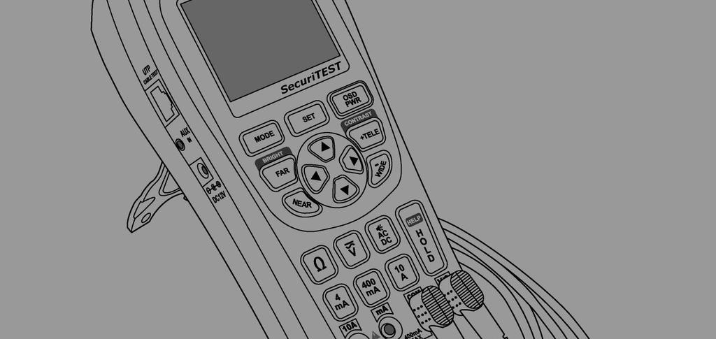
11 NAMES & FUNCTIONS
12 PART NAME FUNCTION Power LED Charge Indicating LED Data Transmitting LED Data Receiving LED LCD Keypad MODE Button SET Button OSD Button FAR Button NEAR Button TELE Button Red LED is on when the system is switched on Green LED is on when being charged Red LED is on when PTZ data is transmitted Red LED is on when PTZ data is received 2.5 Color TFT LCD Controls cameras connected to SecuriTEST Mode Select (Video, MultiMeter, PTZ Control, UTP Test) Used when setup is changed, hold for special functions It toggles OSD & POWER on/off Adjusts PTZ focus (far direction) & Video Mode Brightness Adjust PTZ focus (near direction) & Video Mode Brightness Zoom PTZ (zoom in) & Adjusts Video Mode Contrast WIDE Button Zoom PTZ (zoom out) & Adjusts Video Mode Contrast Direction Keys Moves up, down, right, left for PTZ & for menus and others
13 PART NAME FUNCTION MultiMeter Keys Selects functions of Digital MultiMeter Resistance Button Selects Resistance Mode Voltage Button Selects Voltage Mode Setup Change Button Current Measuring Button 1 Current Measuring Button 2 Current Measuring Button 3 HOLD, HELP Button Test Lead Connection Toggles AC/DC Mode & Selects Continuity Test Selects low Current (below 4mA) Mode Selects Current (below 400mA) Mode Selects Current (up to 10A) Mode Locks Auto-Ranging Function. Hold for HELP Ports for Digital MultiMeter Voltage & Resistance Port Common Port Current Measurement below 400mA Port Current Measurement up to 10A Port
14 PART NAME FUNCTION Input BNC Output BNC Communication Port Connect to camera output to display image on screen Use as pass-through port for camera image or to output video test signal to external monitor Input & Output of communications signals Kickstand Hold unit upright when extended Neck-strap Hook Connect neck-strap here to hang unit Neck-strap Hook Can be used to hang the unit upside down
15 PART NAME FUNCTION UTP Jack AUX Jack DC Power Jack Test jack for UTP Cable Audio, AUX Input Port (for future use) DC Power Input Jack (for over DC12V, 1A) Power S/W Main Power Supply ON/OFF switch
16 GENERAL SPECIFICATIONS Electric Characteristics Image PTZ Operation Test UTP Cable Test Size Input Voltage Battery Built-in Charger TV Type Image Level Protocol Transmission Speed Transmission Mode Kinds of Test 12V ± 10% above 1A Rechargeable Ni-MH battery 6ea (AAsize) Charging Time Operation Time NTSC / PAL Above 8 hrs > 3 hrs 1 Vpp, 140IRE Multi-Protocol support 2400bps ~ 38400bps RS-422, RS-485 Direct / Cross Cable, and Broken or Short-Circuit W 3.5 (88mm) X L 7.9 (190mm) X H 2.3 (58mm)
17 METER SPECIFICATIONS Measuring Item DC Voltage AC Voltage Measured Value Minimum Measuring Accuracy 400mV 100uV ± (0.8% + 2dgts) 4V 40V 400V 4V 40V 400V 400uA 4mV 4mA DC Current 40mA 400mV 400mA 1mV 10mV 100mV 1mV 10mV 100mV 0.2uA 2uA 20uA 200uA ± (1.0% + 2dgts) ± (1.2% + 3dgts) (40Hz ~ 500Hz) ± (1.0% + 2dgts) ± (1.5% + 2dgts) 10A 10A 2mA ± (2.0% + 3dgts)
18 Measuring Item AC Current Resistance Measured Value Minimum Measuring 4mV 400mV 400uA 4mA 40mA 400mA 0.2uV 2uV 20uV 200uV 10A 10A 2mV Accuracy ± (1.5% + 5dgts) (40Hz ~ 500Hz) 40Hz ~ 500Hz ± (1.8% + 5dgts) (40Hz ~ 500Hz) 40Hz ~ 500Hz ± (3.0% + 4dgts) 40Hz ~ 500Hz ± (1.0% + 4dgts) 4k 40k 400k ± (1.0% + 2dgts) 4M 1k ± (2.0% + 4dgts) Continuity 40M 10k ± (3.0% + 5dgts) Beeper is activated when the resistance is below 80 Rated Fuse 250 Volt 800 ma

19 POWER ON/OFF The Power slide switch is located on the side of the handset. Turn the Power slide switch on, and press SecuriTEST. to start To turn off the system, press & hold more than 3 sec. Then, POWER OFF is displayed on the main screen with a beep. Release the button. The power goes off. A rechargeable battery should be plugged in over 8 hrs to fully charge. The charged battery can operate for about 3 hours. When the battery indicator shows below [][], recharge it for use. (Full charge: [][][][]) OSD SETUP SCREEN WHEN POWER IS ON When power is on, the OSD is displayed, and it enters automatically to the video test mode after 3 ~ 5 sec. The initial OSD displays its SecuriTEST version and the initial setup on the screen. Product Version: 2.02 Firmware Version: 2.03 Initital Protocol: PELCO-D TV Mode: NTSC / PAL automatic setup Battery Indicator: [][][][] User Name: User s name (Name can be changed in Main menu) Model & Software versions are subject to be changed without notice.

20 MODE SETUP Pressing the key changes the operation mode between VIDEO, METER, PTZ, and UTP. To directly select a mode, press and hold the for 3 seconds then choose a mode and press the key to select the mode. key Video Tester Mode: In this mode, the image quality of the external input picture signal is tested, or the monitor, etc. is tested by using the picture signal that is output from PATTERN GENERATOR mode. Digital MultiMeter Mode: In this mode, voltage, current, & continuity are tested. PTZ Controller Mode: In this mode, the basic movement of up, down, right, left for PTZ cameras is controlled. Zooming and focus can also be adjusted. UTP Cable Test Mode: UTP cables are tested for straight (direct), crossover, opens, and shorts.
21 View Information Mode: In this mode, the basic information of SecuriTEST can be seen. (Version, battery level, communications protocol and speed.) Main Setting Mode: At this mode, the basic setup of SecuriTEST can be changed. (User s name, auto power off time, beeper, brightness, contrast, etc.) HELP: VIDEO TEST HELP image relevant to the mode displays when the key is pressed on for more than 2 seconds. This function gives a brief explanations of the current function. Connect the output of video output system to the video input BNC of SecuriTEST. Connect the video output BNC of SecuriTEST to the video input terminal of system.
22 OSD Screen Setup VIDEO: NTSC: B [][][][]: C [][][][]: Indicates that the system is in video test mode. Indicates if input or output video signal system is NTSC or PAL. Input video signal is output on LCD screen automatically. Output video signal in Pattern Generator mode can be switched to NTSC or PAL, using or keys. Indicates screen brightness, and the brightness increases gradually by +1 when key is pressed, and decreases gradually by -1 when key is pressed. Returns to the initial setup value when one of the two keys is pressed for more than 3 sec. Indicates screen sharpness, and the brightness increases gradually by +1 when key is pressed, and decreases gradually by -1 when key is pressed. Returns to the initial setup value when one of the two keys is pressed for more than 3 sec.
23 PATTERN GENERATION MODE Enter the PATTERN GENERATION MODE when key is pressed in VIDEO mode. Output is changed between NTSC or PAL, using or keys. Output patterns can be cycled between COLOR BAR, RED, BLUE, GREEN using or keys. COLOR BAR RED BLUE GREEN Press key to return to Video MODE.
24 DIGITAL MULTI-METER Voltage, Current, Resistance, continuity can be measured. WARNING To prevent an electric shock, injury or damage to SecuriTEST, turn off the power supply of the circuit, and discharge all the high-voltage capacitors before testing resistance and continuity. When using the meter function of your SecuriTEST, make sure to turn on its power and set the proper mode before connecting the test leads to the circuit to be tested. WKEY SELECTIONS Press button, and then press button to change to continuity mode Press the button, and then press button to cycle between ACV/DCV. This button is used to test Current below 4mA. This button is used to test Current below 400mA. This button is used to test Current below 10A.
 - Input measured value is indicated in the form of")
25 DESCRIPTION OF METER MODE LCD WINDOW PART FUNCTION DESCRIPTION Test Mode Test Value Measured Value Graph - Resistance test - Continuity test - Set-up tests of DC/AC voltage, current - unit of resistance test is indicated - Indicator of AC or DC value of voltage or current - AC voltage & current are indicated as rms (root mean square) - Input measured value is indicated in the form of graph - Graph is changed automatically equal to the measured value in automatic mode OVER is displayed when higher value is measured than the setup value Measured Value in Memory Hold The measured value is stored and indicated here when SET key is pressed during measurements MODE Display Digital MultiMeter Mode is displayed
 MEASURING RESISTANCE The unit of measurement is. The meter sends low current into the circuit to measure its resistance.")
26 PART FUNCTION DESCRIPTION DC AC OHM VOLT AMP DC Voltage test AC Voltage test Resistance test (Measuring unit: ) Voltage test (Measuring unit: V) Current test (Measuring unit: ma, A) Continuity test (Beeps below 80 ) MEASURING RESISTANCE The unit of measurement is. The meter sends low current into the circuit to measure its resistance. How to measure: Connect the red lead to and the black lead to as shown in the figure above at left. Measure in the resistance mode by pressing on the keypad.

27 TESTING CONTINUITY Continuity indicates the presence of a complete path for current flow. The continuity test features a beeper that sounds when a circuit is complete. The beep allows users to quickly test continuity without having to watch the display. How to test: The resistance mode changes to the continuity mode, when is pressed. The beeper is activated when the resistance between the red probe and black probe is below 80.
 readings.")
28 MEASURING AC & DC VOLTAGE Voltage means the difference in electrical potential between two points. The polarity of AC voltage varies over time, while the polarity of DC is constant over time. The meter displays AC voltage value as rms (root mean square) readings. The rms value means the equivalent dc voltage that can produce the same amount of heat in a resistance as the measured sinewave voltage. How to measure: First, press, the voltage measuring button, then selects AC or DC by pressing. When measuring DC, place the red lead on the + point, and the black lead on - point of the circuit.

29 MEASURING AC & DC CURRENT Current is simply defined as a flow of electrons running through a conductor. To measure current, you must break the circuit under test, and place the meter in series with the circuit. The current measuring range of the meter is 10A max. How to measure: First, turn off the power to the circuit and discharge any high voltage capacitors. Place the red lead into the ma or 10A terminals in accordance with the value to be measured. Select one of the buttons, or. When & are selected, place the red lead on ma. When button is selected, place the red lead on 10A.
30 WARNING Check the position of the test lead set in current test mode. Place the red lead at ma only when below 400mA, and place it at 10A when the value to be tested is over 400mA, or the value is unknown. WARNING Do not attempt to measure voltage when the test leads are connected to the ma or 10A port. Doing so will create a short circuit condition and blow the internal fuse or cause damage to the instrument and possibly cause bodily injury.


31 PTZ CONTROLLER How to connect each terminal and LCD screen PTZ Operation Test: Up, Down, Left, Right, Zoom and Manual focus control are possible. The tester can also be set to various protocols and transmission speeds (baud rates). To use - PTZ Control Setup Screen ADD Setup Screen Protocol Setup Screen Communications Speed Setup Screen

32 - KEYBOARD CONTROL CODE SCREEN - The control commands from the keyboard of an external control are displayed on the screen. Most important is that the communications speed be matched. When you want to know the input signal of an exterior controller, you can see the input data by connecting the communications cable to the RX terminal of the SecuriTEST. Using the PTZ Controls PT control (Up, Down, Left, Right), is performed using the arrow keys. Zoom is controlled using the TELE/WIDE buttons, and focus is controlled with the FAR/NEAR buttons. FUNCTION SETUP of PTZ Press the SHIFT key then use the arrow keys to adjust GPST / SPST / TOUR / and SDP functions. SDP / MENU are displayed on the lower part of LCD screen by pressing the SET key once shortly. GPST: Moves the camera view to the designated preset location. Setup can be from 1 up to 99. (Short for GO TO PRESET). The cursor goes to the GPST position after the key is pressed, select the previously memorized PRESET number using the arrow keys. When the selection is complete, press again to move the camera.
33 SPST: Memorizes PRESET. Setup can range from 1 up to 99. (Short for SET PRESET) First, move the camera to the desired view and press the key, then using the & keys, select SPST and set the address to store using the & keys. Press the key once more to save the address. TOUR: Operates TOUR through SPST points. Can be programmed from 1 to 99. TOUR is set using the same process described for the SPST function. SPD: Sets the speed of the camera. Programmed using the same described for SPST. Range is from 1 to 16. CAUTION Make sure to check communications protocol, transmission speed, and ID.


34 PTZ CONTROL SETUP PTZ ADDR is activated on the upper part on LCD screen, when key is held for more than 3 seconds. The menu also controls the PTZ Protocol and Baud rate. Use the & keys to move between the menus. PTZ ADDR: Setup of PTZ Camera Address Each PTZ camera in a system must have a unique address from 1 to 255 to allow it to be operated by a PTZ controller. Use the PTZ ADDR function to set the address of the camera to control. PROTOCOL: Setup of PTZ PROTOCOL Camera manufacturer use various communications protocols to control the PTZ functions of the camera. Use the PROTOCOL menu to set the output of SecuriTEST to match the protocol of the camera system in use.

35 * BAUDRATE: Setup of TRANSMISSION SPEED The initial setup is 2.4kbps, it can be set from 2.4kbps to 38.4kbps. To escape from the PTZ CONTROL SETUP mode, press the key again. CAUTION Make sure to check for CAMERA ID, PROTOCOL, BAUDRATE when testing. PTZ operation test can not be done when the setup is different from the camera.


36 UTP Cable Tester Connect one end of the UTP cable to be tested to the UTP Cable Test port of SecuriTEST and the other end to the yellow UTP Cable terminator. The connected condition of the cable can be tested, by pressing. The test can detect straight and crossover cables as well as shorts, opens and most miswire conditions. Cross Cable Short-circuit & Disconnection Direct Cable


37 VIEW INFORMATION Mode Setup: First, press key more than 3 sec. and select VIEW INFORMATION on MODE SELECT MENU, then press MAIN SETTING key. Mode Setup: First, press key more than 3 sec. and select MAIN SETTING on MODE SELECT MENU, then press key. Select the item by pressing & keys. Then each setup value can be changed by pressing & keys. A user can enter the name he or she wants by editing USER NAME. SLEEP TIME sets the time that SecuriTEST will remain on when no button presses are detected.
38 This page intentionally left blank.
39 IDEAL Industries, INC. Becker Place Sycamore, IL Customer Service: Made in Korea
Distributed by: Made in Korea
 Distributed by: Manufacturer : Wonwoo Engineering Co., Ltd. Made in Korea TABLE OF CONTENTS Before Reading the User's Manual 1 1. Safety Information 2 WARNING 2 2. Introduction of Rapport337 7 Names &
CCTV Tester. User s Manual
 CCTV Tester User s Manual Table of Contents 1, Safety Information......2 1.1 Precaution before using the tester...2 1.2 Precautions when using the tester...2 1.3 Precautions for battery charging and using...2
Safety Information. Introduction. 1.1 Precaution before using the tester. 1.2 Precautions when using the tester
 CCTV-Test info CCTV-Test allthings.com.au Safety Information 1.1 Precaution before using the tester A. Make sure to read the user s manual before using the product. B. Make sure to check the input and
Rapport mini. Multi Functional CCTV Tester P/N : PRINTED IN KOREA SET MODE. Tx Rx PWR CHG COM V/ FAR OPEN TELE OSD NEAR CLOSE WIDE ~ V
 Rapport mini Multi Functional CCT Tester PWR CHG Tx Rx P/N : 38808730 PRINTED IN KOREA 300 300 COM / TABLE OF CONTENTS TABLE OF CONTENTS BEFORE USING RAPPORT mini SAFETY INFORMATION PRODUCT INTRODUCTION
INSTRUCTION MANUAL. ST-F35TEST CCTV Test Meter
 INSTRUCTION MANUAL ST-F35TEST CCTV Test Meter SAFETY INFORMATION The ST- F35TEST is intended for use in compliance with the local regulations for electrical equipment. The user is not to use the ST- F35TEST
T1 Professional CCTV Tester / Analyser T Version EN triax.com
 T1 Professional CCTV Tester / Analyser Model Item no. T1 301083 Version EN triax.com Table of Contents 1. Safety Information 1.1 Precaution before using the tester 2 1.2 Precautions when using the tester
CCTV Tester. User s Manual
 CCTV Tester User s Manual Table of Contents CCTV Tester User s Manual 1, Safety Information... 2 1.1 Precaution before using the tester... 2 1.2 Precautions when using the tester... 2 1.3 Precautions for
CT-510. Multifunctional CCTV Tester. User Manual
 CT-510 Multifunctional CCTV Tester User Manual Please read these instructions carefully & save this manual for future use Content 1 Safety information... 1 1.1 Precaution before using the tester... 1 1.2
User s Manual Model: EX-TB2
 CCTV Tester User s Manual Model: EX-TB2 CCTV Tester User s Manual Table of Contents 1, Safety Information...2 1.1 Precaution before using the tester...2 1.2 Precautions when using the tester...2 1.3 Precautions
USER S MANUAL. CCTV TESTER Model:TM035
 USER S MANUAL CCTV TESTER Model:TM035 3.5 TFT LCD Colour Monitor with LED Back light, Composite Video In/Out BNC, 12volts output for Camera, Colour Pattern Generator, Multi-meter, PTZ controller, LAN cable
Content. 1, Safety Information...1
 CCTV User s Manual Content 1, Safety Information...1 1.1Precautions before using the tester...2 1.2Precautions during using the tester...2 1.3Precautions for battery charging and usage...2 2, Product Introduction...2
USER S MANUAL. CCTV TesterPro. Ver:STPV
 USER S MANUAL CCTV TesterPro Ver:STPV1.32 2009.5 Page.1. Table of Content 1 Safety Information -----------------------------------------------------------------------------------3 2 Introduction----------------------------------------------------------------------------------------------4
USER S MANUAL. CCTV Tester - MC3.5H-BP-PTZ
 USER S MANUAL CCTV Tester - MC35H-BP-PTZ Thank you for purchasing the CCTV security tester Please read the manual before using the CCTV tester and use properly For using the CCTV tester safely, please
USER S MANUAL. CCTV TesterPro
 USER S MANUAL CCTV TesterPro Thank you for purchasing the CCTV security tester. Please read the manual before using the CCTV testerpro, and use properly. For using the CCTV testerpro safely, please first
SBS -600 Graphical Digital Multimeter SBS- 700 Multi-Function Oscilloscope. Quick Start Guide
 SBS -600 Graphical Digital Multimeter SBS- 700 Multi-Function Oscilloscope Quick Start Guide 99 Washington Street Melrose, MA 02176 Phone 781-665-1400 Toll Free 1-800-517-8431 Visit us at www.testequipmentdepot.com
2 in 1 LAN Tester and Multimeter Model:
 2 in 1 LAN Tester and Multimeter Model: 72-8495 1 IMPORTANT SAFETY INFORMATION Please read these instructions carefully before use and retain for future reference. This instrument is designed and manufactured
IDEAL INDUSTRIES, INC. TECHNICAL MANUAL MODELS:
 IDEAL INDUSTRIES, INC. TECHNICAL MANUAL MODELS: 61-773 61-775 The Service Information provides the following information: Precautions and safety information Specifications Performance test procedure Calibration
Instruction Manual. 2in1 LAN Tester & Multimeter. Model: 57314
 Instruction Manual 2in1 LAN Tester & Multimeter Model: 57314 1 Contents Introduction... Features... Safety Precautions.. Meter Description... Electrical Specification... Operation.. AutoRanging Multimeter.
700 Series 200 Amp Clamp Meters
 700 Series 200 Amp Clamp Meters #61-700 #61-701 #61-702 1 2 3 6 5 7 4 8 1. Non-contact voltage (NCV) (#61-701 and #61-702) With the NCV tab on the tip of the clamp close to an AC voltage, press the NCV
Autoranging True RMS Multimeter User Manual
 Autoranging True RMS Multimeter User Manual Please read this manual before switching the unit on. Important safety information inside. Contents Page 1. Safety Information... 4 2. Safety Symbols... 5 3.
2 in1 LAN Tester & Multimeter. Model: PCE-LT 1
 www.pce-industrial-needs.com Tursdale Technical Services Ltd Unit N12B Tursdale Business Park Co. Durham DH6 5PG United Kingdom Phone: +44 ( 0 ) 191 377 3398 Fax: +44 ( 0 ) 191 377 3357 info@tursdaletechnicalservices.co.uk
S-14 S-14. Compact Digital Multimeter. Compact Digital Multimeter
 S-14 Compact Digital Multimeter S-14 Compact Digital Multimeter SAFETY INFORMATION The following safety information must be observed to insure maximum personal safety during the operation at this meter
IDEAL INDUSTRIES INC. TECHNICAL MANUAL MODEL:
 IDEAL INDUSTRIES INC. TECHNICAL MANUAL MODEL: 61-795 The Service Information provides the following: Precautions and safety information Specifications Performance test procedure Calibration and calibration
IDEAL INDUSTRIES, INC. TECHNICAL MANUAL MODEL:
 IDEAL INDUSTRIES, INC. TECHNICAL MANUAL MODEL: 61-796 The Service Information provides the following information: Precautions and safety information Specifications Performance test procedure Calibration
OWNER S MANUAL 9908-TE. HIGH PRECISION AUTO-RANGING DC/True RMS AC BENCH-TOP DIGITAL MULTIMETER
 OWNER S MANUAL 9908-TE HIGH PRECISION AUTO-RANGING DC/True RMS AC BENCH-TOP DIGITAL MULTIMETER IMPORTANT! Read and understand this manual before using the instrument. Failure to understand and comply with
OPERATING INSTRUCTION
 OPERATING INSTRUCTION AUTORANGING MULTIMETER MAX Ω F C 10A MAX every 15 min. COM V SAFETY INFORMATION The following safety information must be observed to insure maximum personal safety during the operation
OPERATING INSTRUCTION. Pen-Type Digital Multimeter
 OPERATING INSTRUCTION Pen-Type Digital Multimeter International Safety Symbols This symbol, adjacent to another symbol or terminal, indicates the user must refer to the manual for further information.
Model INSTRUCTION MANUAL DIGITAL MULTIMETER
 Model 57040 INSTRUCTION MANUAL DIGITAL MULTIMETER SAFETY INFORMATION This multimeter has been designed according to IEC 1010 concerning electronic measuring instruments with an overvoltage category (CAT
Owner's Manual. True RMS Multimeter. Model No Safety Operation Maintenance Español
 Owner's Manual True RMS Multimeter Model No. 82023 CAUTION: Read, understand and follow Safety Rules and Operating Instructions in this manual before using this product. Safety Operation Maintenance Español
Digital Clamp-on Meter Instruction Manual
 265 Digital Clamp-on Meter Instruction Manual TABLE OF CONTENTS A. INTRODUCTION 1. Congratulations...3 2. Product Description...3 3. Declaration of Conformity...4 B. SAFETY CONSIDERATIONS...5 C. TECHNICAL
User Guide True RMS Multimeter Extech EX205T
 User Guide Extech EX205T True RMS Digital Multimeter Extech EX210T True RMS Digital Multimeter IR True RMS Multimeter Extech EX205T Introduction Thank you for selecting the Extech EX205T True RMS Auto-ranging
USER S MANUAL. CCTV TesterPro
 USER S MANUAL CCTV TesterPro Thank you for purchasing the CCTV security tester. Please read the manual before using the CCTV testerpro, and use properly. For using the CCTV testerpro safely, please first
B-Qtech Electronics Co.,Ltd / USER S MANUAL. CCTV TesterPro. Stest-895. Ver:STPV
 www.b-qtech.com B-Qtech Electronics Co.,Ltd Email: sales@b-qtech.com / bqshelly@gmail.com USER S MANUAL CCTV TesterPro Stest-895 Ver:STPV1.32 2009.5 Ms Shelly Yoe (GM) MSN:bqshelly@hotmail.com / Skype:
3.5 HVGA TFT-LCD Wide angle screen display/480 (RGB)*320 resolution / AHD TEST /PTZ
*320 resolution / AHD TEST /PTZ") AHD Tester HD-2800A 3.5 HVGA TFT-LCD Wide angle screen display/480 (RGB)*320 resolution / AHD TEST /PTZ control/ Color bar generator /12V 1A power output The new HD coaxial tester is developed for the
AHD Tester HD-2800A 3.5 HVGA TFT-LCD Wide angle screen display/480 (RGB)*320 resolution / AHD TEST /PTZ control/ Color bar generator /12V 1A power output The new HD coaxial tester is developed for the
User Manual. 400Amp AC Clamp Meter + NCV. Model MA430. Additional User Manual Translations available at
 User Manual 400Amp AC Clamp Meter + NCV Model MA430 Additional User Manual Translations available at www.extech.com Introduction Congratulations on your purchase of this Extech MA430 Clamp Meter. This
AutoRanging Digital MultiMeter
 Owner's Manual AutoRanging Digital MultiMeter Model No. 82175 CAUTION: Read, understand and follow Safety Rules and Operating Instructions in this manual before using this product. Safety Operation Maintenance
Model: Pro93 TRUE RMS LEAKAGE CURRENT TESTER
 Model: Pro93 TRUE RMS LEAKAGE CURRENT TESTER CONTENTS TITLE PAGE I. Safety Information.......1 Environmental Conditions... 1 Explanation of Symbols..... 1 II. Specification..... 2 General Specification...
Model R5005. Instruction Manual. True RMS Industrial Multimeter. reedinstruments. www. com
 Model R5005 True RMS Industrial Multimeter Instruction Manual reedinstruments com Table of Contents Safety... 4 Features... 5 Specifications...5-6 Instrument Description...7-8 Operating Instructions...9-13
DM-918 OPERATIONS MANUAL AUTORANGING MULTIMETER
 DM-918 OPERATIONS MANUAL AUTORANGING MULTIMETER SAFETY INFORMATION The following safety information must be observed to ensure maximum personal safety during the operation of this meter: This meter is
USER MANUAL. Mini Multimeter with Non-Contact Voltage Detector (NCV) Model EX310
 Model EX310") USER MANUAL Mini Multimeter with Non-Contact Voltage Detector (NCV) Model EX310 Introduction Congratulations on your purchase of the Extech EX310 MultiMeter. The EX310 offers AC/DC Voltage, AC/DC Current,
USER MANUAL Mini Multimeter with Non-Contact Voltage Detector (NCV) Model EX310 Introduction Congratulations on your purchase of the Extech EX310 MultiMeter. The EX310 offers AC/DC Voltage, AC/DC Current,
Mini Digital Multimeter
 User Manual Mini Digital Multimeter Model MN15A Additional User Manual Translations available at www.extech.com Introduction Congratulations on your purchase of the Extech MN15A MultiMeter. The MN15A offers
User's Guide. Digital Multimeter. Model MN42
 User's Guide Digital Multimeter Model MN42 Introduction Congratulations on your purchase of the Extech MN42 MultiMeter. The MN42 offers AC/DC Voltage, DC Current, and Resistance testing. Proper use and
MTP INSTRUCTION MANUAL
 DT-118B MTP INSTRUCTION MANUAL Pocket Autoranging Digital Multimeter 3 in 1 Model MTP-1025 Auto Ran ging DMM Hz% A OFF V AU TO PO WER OFF MTP Instruments Table of Contents Introduction Page 1 Features
Mini Digital Multimeter Model MN15. User's Guide
 Mini Digital Multimeter Model MN15 User's Guide Introduction Congratulations on your purchase of the Extech MN15 MultiMeter. The MN15 offers AC/DC Voltage, AC/DC Current, Resistance, Diode, and Continuity
3.5 LCD CCTV Test Monitor ART
 3.5 LCD CCTV Test Monitor ART. 43600 Via Don Arrigoni, 5 24020 Rovetta S. Lorenzo (Bergamo) http://www.comelit.eu e-mail: export.department@comelit.it SAFETY PRECAUTIONS Please read before using The lightning
5.6" Multi-function Monitor
 5.6" Multi-function Monitor User s Manual Please read this Manual carefully before use of this product, and keep it handy for future reference. I. Packing List.. 2 II. Product Appearance... 3-5 III. Product
Mini Digital Multimeter
 User's Guide Mini Digital Multimeter Model MN15 99 Washington Street Melrose, MA 02176 Phone 781-665-1400 Toll Free 1-800-517-8431 Visit us at www.testequipmentdepot.com Back to the Extech MN15/MN16 Series
3700 SERIES USER MANUAL
 SAFETY GUIDE This manual contains the precautions necessary to ensure your personal safety as well as for protection for the products and the connected equipment. These precautions are highlighted with
IDEAL INDUSTRIES, INC. TECHNICAL MANUAL MODEL:
 99 Washington Street Melrose, MA 02176 Fax 781-665-0780 TestEquipmentDepot.com IDEAL INDUSTRIES, INC. TECHNICAL MANUAL MODEL: 61-609 The Service Information provides the following information: Precautions
POCKET MULTIMETER Model No: MM18
 INSTRUCTIONS FOR: POCKET MULTIMETER Model No: MM18 Thank you for purchasing a Sealey product. Manufactured to a high standard this product will, if used according to these instructions and properly maintained,
User's Guide. MiniTec TM Series Model MN25 MultiMeter
 User's Guide MiniTec TM Series Model MN25 MultiMeter Warranty EXTECH INSTRUMENTS CORPORATION warrants this instrument to be free of defects in parts and workmanship for one year from date of shipment (a
Model A Mini AC/DC Clamp Meter. User's Guide
 Model 380950 80A Mini AC/DC Clamp Meter User's Guide Introduction Congratulations on your purchase of the Extech 80A Mini AC/DC Clamp Meter. The Model 380950 measures AC/DC Current, AC/DC Voltage, Resistance,
ATK-2040 AC/DC TRMS Watt Clamp Meter Users Manual
 ATK-2040 AC/DC TRMS Watt Clamp Meter Users Manual EN 61010-2-032 CAT II 600V, CAT III 300V Pollution Degree 2 SYMBOLS showed on the clamp meter or in this manual: Caution, risk of danger. Refer to accompanying
OPERATOR S INSTRUCTION MANUAL DIGITAL MULTIMETER
 OPERATOR S INSTRUCTION MANUAL DIGITAL MULTIMETER SAFETY INFORMATION This multimeter has been designed according to IEC 1010 concerning electronic measuring instruments with an overvoltage category (CATⅡ)
Digital Multimeter Instruction Manual
 126 Digital Multimeter Instruction Manual TABLE OF CONTENTS page A. INTRODUCTION 1. Congratulations..................3 2. Product Description..............3 3. EC Declaration of Conformity........4 B.
Digital Clamp-on Meter Instruction Manual
 255 Digital Clamp-on Meter Instruction Manual TABLE OF CONTENTS A. INTRODUCTION 1. Congratulations...3 2. Product Description...3 3. Declaration of Conformity...4 B. SAFETY CONSIDERATIONS...5 C. TECHNICAL
R5050. Model. Instruction Manual. TRMS AC/DC Clamp Meter. reedinstruments. www. com
 Model R5050 TRMS AC/DC Clamp Meter Instruction Manual reedinstruments com Table of Contents Safety... 3 Features... 4 Specifications...4-6 Instrument Description...7-8 Measurement Procedures...9-12 Battery
Digital Clamp-on Meter Amp Plus. Instruction Manual
 296 Digital Clamp-on Meter Amp Plus Instruction Manual TABLE OF CONTENTS A. INTRODUCTION 1. Congratulations...3 2. Product Description...3 3. Declaration of Conformity...4 B. SAFETY CONSIDERATIONS...5
USER MANUAL. For XLCD17-LED XLCD19-LED
 USER MANUAL For XLCD17-LED XLCD19-LED 2 TABLE OF CONTENTS CE information ------------------------------------------------------------------------ 4 Safety Precautions -------------------------------------------------------------------
BENCH-TOP DIGITAL MULTIMETER INSTRUCTION MANUAL
 BENCH-TOP DIGITAL MULTIMETER INSTRUCTION MANUAL SK-4033 / SK-4035 Thank you for purchasing KAISE MODEL SK-4033/4035 BENCH-TOP DIGITAL MULTIMETERS. To obtain the maximum performance of this instrument,
Handheld Video Magnifier
 Zoomax TM Snow Handheld Video Magnifier V1.1 1 Contents Description...3 Accessories...3 Compositions:...4 Operation...5 Battery installation...5 Charging the battery...6 Install short strap...6 Operation
Digital Clamp-on Meter Amp Plus. Instruction Manual
 293 Digital Clamp-on Meter Amp Plus Instruction Manual TABLE OF CONTENTS A. INTRODUCTION 1. Congratulations...3 2. Product Description...3 3. Declaration of Conformity...4 B. SAFETY CONSIDERATIONS...5
Marshall M-CT710. Camera-Top Monitor. Owner s Manual
 Marshall M-CT710 Camera-Top Monitor Owner s Manual Dear users: Thank you for purchasing Marshall s M-CT710 HD LCD Monitor. This 7 Pro HD LCD Monitor is designed to be used as an external video display,
FastCam Outdoor Speed Dome Camera
 FastCam Outdoor Speed Dome Camera CC-9760 & CC-9760-I USER INSTRUCTION MANUAL Version: V1.2 Doc No.: 20051114001 1 A BOUT THIS GUIDE Conventions used in this guide To make sure that you perform certain
CamView PTZ Instruction Manual
 CamView PTZ TM Instruction Manual 84-887 REV A 8/12 Thank you for purchasing the Triplett CamView PTZ CCTV Monitor with PTZ Controller. Please read the complete manual carefully before using the product.
Bench Multimeter. Users Manual
 Bench Multimeter Users Manual Bench Multimeter Users Manual Introduction This manual contains information and warnings, which must be followed to ensure safe operation and retain the meter in safe condition.
Introduction. Chapter 2
 The Vantage PRO unit (Figure 2-1) combines a digital and graphing multimeter, lab scope and ignition scope with a powerful diagnostic database. Figure 2-1 Vantage PRO This diagnostic database gives you
True RMS Multimeter with IR Thermometer
 Owner's Manual True RMS Multimeter with IR Thermometer Model No. 82024 CAUTION: Read, understand and follow Safety Rules and Operating Instructions in this manual before using this product. Safety Operation
HuddleCamHD RS-232 Joystick Controller Model Number: HC-JOY
 HuddleCamHD RS-232 Joystick Controller Model Number: HC-JOY JOYSTICK KEYBOARD INSTALLATION & OPERATION MANUAL Rev 1.0 6/15 Easy pan, tilt & zoom controls for any RS-232 VISCA protocol camera! Controls
Digital Multimeter User's Manual
 Digital Multimeter User's Manual MS8238C MS8238C DIGITAL MULTIMETER FUNC HOLD RAN NCV TEMP V μa ma 12V 9V 1.5V CAT III COM FUSED 10A 30 sec. every 15 min. 200mA FUSED Autorange Auto power off TEMP maμav
Model 3526-B Digi-Probe Multimeter
 Model 3526-B Digi-Probe Multimeter CAUTION: Read, understand and follow all Safety Rules and Operating Instructions in this instruction manual before using this product. 84-797 Rev A The Model 3526-B has
Bluetooth/USB Data Logger USER S MANUAL. Hantek 365A/B/C/D/E/F V
 Bluetooth/USB Data Logger USER S MANUAL Hantek 365A/B/C/D/E/F V 1.0.3 www.hantek.com Content General Safety Summary... 1 Chapter 1 Getting Start... 3 1.1 General Check... 4 1.2 The User interface... 5
TENMA INSTRUCTION MANUAL MULTI-TESTER
 TENMA 72-9165 INSTRUCTION MANUAL MULTI-TESTER 6 IN 1 SOUND LEVEL LIGHT HUMIDITY TEMPERATUPRE MULTIMETER Non-contact AC Voltage Test TABLET OF CONTENTS 1. INTRODUCTION 2 2. INFORMATION FOR SAFETY 3 3. FEATURES
User's Guide. 800 Amp Clamp Meters. EX710 AC Clamp meter EX720 True RMS AC Clamp meter EX730 AC/DC True RMS Clamp meter
 User's Guide 800 Amp Clamp Meters EX710 AC Clamp meter EX720 True RMS AC Clamp meter EX730 AC/DC True RMS Clamp meter Introduction Congratulations on your purchase of the EX710, EX720, or EX730 Clamp DMM.
HD Coaxial Tester Manual V2.10
 V2.10 Thank you for purchasing the HD CCTV security tester. Please read the manual before using the HD coaxial tester and use properly. For using the HD coaxial tester safely, please first read the Safety
I. PANEL DESCRIPTION... 1
 Table of Contents I. PANEL DESCRIPTION... 1 II. OPERATING INSTRUCTION... 7 1. MA OUTPUT... 7 1A. GENERAL OPERATION 4-20MA... 7 1B. SELECT 0-20MA OR 0-24MA... 8 1C. ENTER A VALUE LESS THAN 1... 9 2. % (PERCENTAGE)
RS Stock No Instruction Manual RS Input Data Logging Thermometer
 RS Stock No. 730-0458 Instruction Manual RS-1384 4 Input Data Logging Thermometer EN FR IT DE ES TABLE OF CONTENTS / EN TITLE TABLE OF CONTENTS PAGE 1. INTRODUCTION FEATURE... 1 2. SPECIFICATIONS... 2
DIGITAL MULTIMETER 4 1/2 digits, True RMS Model : DM-9027T
 DIGITAL MULTIMETER 4 1/2 digits, True RMS Model : DM-9027T Caution Symbol Caution : * Risk of electric shock! Caution : * Do not apply the overload voltage, current to the input terminal! * Remove test
User s Guide. 600A True RMS AC/DC Clamp Meter. Model 38389
 User s Guide 600A True RMS AC/DC Clamp Meter Model 38389 Safety International Safety Symbols This symbol, adjacent to another symbol or terminal, indicates the user must refer to the manual for further
INTRODUCTION PARTS & ACCESSORIES STRUCTURE USING YOUR EXPLORĒ ATTACHING THE STRAP OPERATING YOUR EXPLORĒ
 INTRODUCTION... 1 1. PARTS & ACCESSORIES... 2 2. STRUCTURE... 3 3. USING YOUR EXPLORĒ 3... 4 3.1 ATTACHING THE STRAP... 5 3.2 OPERATING YOUR EXPLORĒ 3... 5 3.2.1 Power On/Off... 5 3.2.2 Zoom In/Zoom Out...
7 LCD CCTV Test monitor. Quick guide
 Thank you for purchasing our product. Speco Technologies is constantly developing and improving products. We reserve the right to modify product design and specifications without notice and without incurring
USER'S MANUAL DCL-650
 USER'S MANUAL Clamp on Multimeter - Compact Design True RMS AC/DC DCL-650 CIRCUIT-TEST ELECTRONICS www.circuittest.com Safety International Safety Symbols This symbol, adjacent to another symbol or terminal,
DC / AC True RMS Watt Clamp DMM
 99 Washington Street Melrose, MA 02176 Phone 781-665-1400 Toll Free 1-800-517-8431 Visit us at www.testequipmentdepot.com Back to the Extech 380940 Product Page DC / AC True RMS Watt Clamp DMM 10W or 100mA
CM-220 True RMS AC CLAMP METER INSTRUCTION MANUAL
 CM-220 True RMS AC CLAMP METER INSTRUCTION MANUAL Safety International Safety Symbols This symbol, adjacent to another symbol or terminal, indicates the user must refer to the manual for further information.
1. REMOTE SENSOR 2. A/V IN JACK 4. DC 12V IN 5. TFT-LCD SCREEN 6. EARPHONE JACK 7. SPEAKER 9. TV/AV BUTTON 13. ROD ANTENNA 14.
 1 2 WARNINGS The exclamation point within the triangle is a warning sign alerting the user of important instructions accompanying the product. The lightening flash with arrowhead symbol within the triangle
the excelptz range Installation and Operation Manual Speed Dome Camera Controller Version 1.0 For updates to these instructions visit
 the excelptz range Installation and Operation Manual Speed Dome Camera Controller MODEL PTZ730 Version 1.0 For updates to these instructions visit www.excelptz.com CONTENTS Page 1. Summary 3 2. Keyboard
Multifunction Calibrator
 Multifunction Calibrator Model CL TC - - - C V _ TECPEL CO., LTD. Features:. - (KΩ load, V Loop Supply). -.,-.V, -.V. K, J, E, T Thermocouple ( C and ). Frequency -.. Basic Accuracy. Easy Key-pad Operation.
7032 Digital-Analog Multimeter
 7032 Digital-Analog Multimeter OPERATOR S MANUAL CONTENTS: 1. Safety precautions and procedures 1 1.1. Preliminary 1 1.2. During Use 2 1.3. After Use.. 2 2. General Description. 3 3. Preparation for Use..
NTP-5521/5531/5561 SWITCHING MODE POWER SUPPLY
 NTP-5521/5531/5561 SWITCHING MODE POWER SUPPLY USER MANUAL Keep this manual in a safe place for quick reference at all times. This manual contains important safety and operation instructions for correct
Test Equipment Depot Washington Street Melrose, MA TestEquipmentDepot.com. TRIPLETT Model 9055
 Test Equipment Depot - 800.517.8431 99 Washington Street Melrose, MA 02176 - TestEquipmentDepot.com TRIPLETT Model 9055 6-in-1 EnviroMeter with Sound Light, Temperature and Humidity Instruction Manual
WARNING CAUTION 1. SAFETY
 Instructions for: Professional auto ranging Digital Multimeter - 8 Function MOdel No: TM102 Thank you for purchasing a Sealey product. Manufactured to a high standard, this product will, if used according
General Warranty. For more details, please refer to the user manual, it can be downloaded at
 General Warranty OWON warrants that the product will be free from defects in materials and workmanship for a period of 1 year from the date of purchase of the product by the original purchaser from the
Operating Instructions
 Bracken Hill South West Industrial Estate Peterlee Co Durham SR8 2SW ENGLAND Tel: +44(0)191 5863511 www.seaward.co.uk sales@seaward.co.uk service@seaward.co.uk Part Number 344A550 Revision 1 2006 Seaward
Keypad with joystick and LCD display USER MANUAL
 Keypad with joystick and LCD display 430 502 430 603 USER MANUAL LE03722AA TABLE OF CONTENTS INTRODUCTION. FEATURES...4 2. HARDWARE OVERVIEW...4 3. SYSTEM CONFIGURATION AND WIRING...7 SYSTEM INSTALLATION
99 Washington Street Melrose, MA Phone Toll Free Visit us at INSTRUCTION MANUAL
 99 Washington Street Melrose, MA 02176 Phone 781-665-1400 Toll Free 1-800-517-8431 Visit us at www.testequipmentdepot.com INSTRUCTION MANUAL Test Equipment Depot - 800.517.8431-99 Washington Street Melrose,
Mini Digital Multimeter
 User's Guide Mini Digital Multimeter Model MN15 Introduction Congratulations on your purchase of the Extech MN15 MultiMeter. The MN15 offers AC/DC Voltage, AC/DC Current, Resistance, Diode, and Continuity
4.3 Testing Analog Cameras
 20 CamView IP Pro Series Combined User Manual 4.3 Testing Analog Cameras 4.3.1 Overview You can test standard Analog (NTSC/PAL) cameras with the Pro model, NTSC/PAL & HD-CVI with the Pro-C model, or you
ETHOS Auto Ranging Digital Multimeter
 ETHOS 5020 Auto Ranging Digital Multimeter 1 1. SAFETY INFORMATION SAFETY SYMBOLS Warning! Dangerous Voltage (Risk of electric shock). Caution! Refer to the user s manual before using this Meter. Double
Keysight U1602B and U1604B Handheld Digital Oscilloscopes
 Keysight U1602B and U1604B Handheld Digital Oscilloscopes Quick Start Guide Safety Information Use the product only as specified by the manufacturer. Do not install substitute parts or perform any unauthorized
Video Borescope Inspection Camera
 Owner's Manual Video Borescope Inspection Camera Model 82027 CAUTION: Read, understand and follow Safety Rules and Operating Instructions in this manual before using this product. Safety Operation Maintenance