Implement Inter-VLAN Routing. LAN Switching and Wireless Chapter 6 Modified by Tony Chen 11/01/2008
|
|
|
- Maryann Day
- 5 years ago
- Views:
Transcription

1 Implement Inter-VLAN Routing LAN Switching and Wireless Chapter 6 Modified by Tony Chen 11/01/2008 ITE I Chapter Cisco Systems, Inc. All rights reserved. Cisco Public 1
2 Notes: If you see any mistake on my PowerPoint slides or if you have any questions about the materials, please feel free to me at Thanks! Tony Chen College of DuPage Cisco Networking Academy 2
3 Objectives Explain to the satisfaction of a qualified instructor how network traffic is routed between VLANs in a converged network. Configure inter-vlan routing on a router to enable communications between end-user devices on separate VLANs Troubleshoot common inter-vlan connectivity issues. 3

4 Introducing Inter-VLAN Routing Now that you know how to configure VLANs on a network switch, the next step is to allow devices connected to the various VLANs to communicate with each other. In a previous chapter, you learned that each VLAN is a unique broadcast domain, so computers on separate VLANs are, by default, not able to communicate. There is a way to permit these end stations to communicate; it is called inter-vlan routing. In this topic, you will learn what inter-vlan routing is and the different ways to accomplish inter-vlan routing. In this chapter, we focus on one type of inter-vlan routing using a separate router connected to the switch infrastructure. We define inter-vlan routing as a process of forwarding traffic from one VLAN to another VLAN using a router. VLANs are associated with unique IP subnets on the network. When using a router to facilitate inter-vlan routing, the router interfaces can be connected to separate VLANs. Devices on those VLANs send traffic through the router to reach other VLANs. As you can see in the figure, traffic from PC1 on VLAN10 is routed through router R1 to reach PC3 on VLAN30. 4

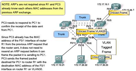
5 Introducing Inter-VLAN Routing In this example, the router was configured with 2 separate interfaces to interact with the different VLANs and routing. Routing is performed by connecting different physical router interfaces to different physical switch ports. The switch ports connect to the router in access mode Each switch interface assigned to a different static VLAN. In this example. 1. PC1 on VLAN10 is communicating with PC3 on VLAN30 through R1. 2. PC1 and PC3 are on different VLANs and have IP addresses on different subnets. 3. R1 has a separate interface configured for each of the VLANs. 4. PC1 sends unicast traffic destined for PC3 to S2 on VLAN10, where it is then forwarded out the trunk interface to S1. 5. Switch S1 then forwards the unicast traffic to R1 on interface F0/0. 6. The router routes the unicast traffic through to its interface F0/1, which is connected to VLAN The router forwards the unicast traffic to S1 on VLAN S1 then forwards the unicast traffic to S2 through the trunk link, after which S2 can then forward the unicast traffic to PC3 on VLAN30. 5


6 Introducing Inter-VLAN Routing "Router-on-a-stick" However, not all inter-vlan routing configurations require multiple physical interfaces. "Router-on-a-stick" is a type of router configuration in which a single physical interface routes traffic between multiple VLANs on a network. The router interface is configured to operate as a trunk link and is connected to a switch port configured in trunk mode. The router performs the inter-vlan routing by accepting VLAN tagged traffic on the trunk interface coming from the adjacent switch and internally routing between the VLANs using subinterfaces. The router then forwards the routed traffic-vlan tagged for the destination VLAN-out the same physical interface. Subinterfaces are multiple virtual interfaces, associated with one physical interface. Subinterfaces are configured for different subnets corresponding to their VLAN assignment to facilitate logical routing before the data frames are VLAN tagged and sent back out the physical interface. 6


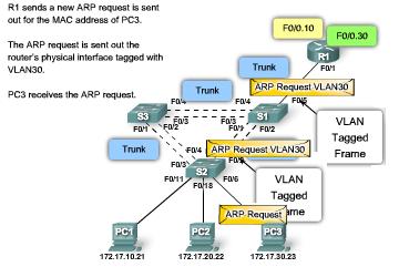
7 router-on-a-stick The figure shows how a router-on-a-stick performs its routing function. 1. PC1 on VLAN10 is communicating with PC3 on VLAN30 through router R1 using a single, physical router interface. 2. PC1 sends its unicast traffic to switch S2. 3. Switch S2 then tags the unicast traffic as originating on VLAN10 and forwards the unicast traffic out its trunk link to switch S1. 4. Switch S1 forwards the tagged traffic out the other trunk interface on port F0/5 to the interface on router R1. 5. Router R1 accepts the tagged unicast traffic on VLAN10 and routes it to VLAN30 using its configured subinterfaces. 6. The unicast traffic is tagged with VLAN30 as it is sent out the router interface to switch S1. 7. Switch S1 forwards the tagged unicast traffic out the other trunk link to switch S2. 8. Switch S2 removes the VLAN tag of the unicast frame and forwards the frame out to PC3 on port F0/6. 7


8 Inter-VLAN Routing Layer 3 switch Some switches can perform Layer 3 functions, replacing the need for dedicated routers to perform basic routing on a network. 1. PC1 on VLAN10 is communicating with PC3 on VLAN30 through switch S1 using VLAN interfaces configured for each VLAN. 2. PC1 sends its unicast traffic to switch S2. 3. Switch S2 tags the unicast traffic as originating on VLAN10 as it forwards the unicast traffic out its trunk link to switch S1. 4. Switch S1 removes the VLAN tag and forwards the unicast traffic to the VLAN10 interface. 5. Switch S1 routes the unicast traffic to its VLAN30 interface. 6. Switch S1 then retags the unicast traffic with VLAN30 and forwards it out the trunk link back to switch S2. 7. Switch S2 removes the VLAN tag of the unicast frame and forwards the frame out to PC3 on port F0/6. Configuring inter-vlan routing on a multilayer switch (CCNP) 8

9 Using the Router as a Gateway The traditional model: Using the Router as a Gateway Traditional routing requires routers to have multiple physical interfaces to facilitate inter-vlan routing. Each interface is also configured with an IP address for the subnet associated with the particular VLAN that it is connected to. In this configuration, network devices can use the router as a gateway to access the devices connected to the other VLANs. The routing process requires the source device to determine if the destination device is local or remote to the local subnet. The source device accomplishes this by comparing the source and destination addresses against the subnet mask. Once the destination address has been determined to be on a remote network, the source device has to identify where it needs to forward the packet to reach the destination device. The source device examines the local routing table to determine where it needs to send the data. Typically, devices use their default gateway as the destination for all traffic that needs to leave the local subnet. The default gateway is the route that the device uses when it has no other explicitly defined route to the destination network. The router interface on the local subnet acts as the default gateway for the sending device. 9


10 Using the Router as a Gateway Once the source device has determined that the packet must travel through the local router interface on the connected VLAN,


11 Using the Router as a Gateway


12 Interface Configuration In global configuration mode, switch to interface configuration mode. interface F0/0 is configured with IP address and subnet mask interface F0/1 is configured with IP address and subnet mask Routing Table As you can see in the example, the routing table has two entries, one for network and the other for network Notice the letter C to the indicates that the route is local for a connected interface, which is also identified in the route entry. Traditional inter-vlan routing using physical interfaces does have a limitation. As the number of VLANs increases on a network, the physical approach of having one router interface per VLAN quickly becomes hindered by the physical hardware limitations of a router. Routers have a limited number of physical interfaces that they can use to connect to different VLANs. 12

13 Interface Configuration: subinterface To overcome the hardware limitations of inter-vlan routing based on router physical interfaces, virtual subinterfaces and trunk links are used, as in the router-on-a-stick example described earlier. Subinterfaces are software-based virtual interfaces that are assigned to physical interfaces. Each subinterface is configured with its own IP address, subnet mask, and unique VLAN assignment, allowing a single physical interface to simultaneously be part of multiple logical networks. This is useful when performing inter-vlan routing on networks with multiple VLANs and few router physical interfaces. Functionally, the router-on-a-stick model for inter- VLAN routing is the same as using the traditional routing model, but instead of using the physical interfaces to perform the routing, subinterfaces of a single interface are used. 13


14 Interface Configuration: subinterface In the figure, PC1 wants to communicate with PC3. PC1 is on VLAN10, and PC3 is on VLAN30. For PC1 to communicate with PC3, PC1 needs to have its data routed through router R1 using configured subinterfaces


15 Interface Configuration: subinterface


16 Subinterface Configuration The syntax for the subinterface is always the physical interface, followed by a period and a subinterface number. The subinterface number is configurable, but it is typically associated to reflect the VLAN number. In the example, the subinterfaces use 10 and 30 as subinterface numbers to make it easier to remember which VLANs they are associated with. Unlike a typical physical interface, subinterfaces are not enabled with the no shutdown command at the subinterface configuration mode. Instead, when the physical interface is enabled with the no shutdown command, all the configured subinterfaces are enabled. Likewise, if the physical interface is disabled, all subinterfaces are disabled. Before assigning an IP address to a subinterface, the subinterface needs to be configured to operate on a specific VLAN using the encapsulation dot1q vlan id command. 16
17 Interface and Subinterface Using either physical interfaces or subinterfaces have advantages and disadvantage. Port Limits Physical interfaces are configured to have one interface per VLAN. On networks with many VLANs, using a single router to perform inter- VLAN routing is not possible. Subinterfaces allow a router to scale to accommodate more VLANs than the physical interfaces permit. Performance Because there is no contention for bandwidth on physical interfaces, physical interfaces have better performance for inter-vlan routing. When subinterfaces are used for inter-vlan routing, the traffic being routed competes for bandwidth on the single physical interface. On a busy network, this could cause a bottleneck for communication. Access Ports and Trunk Ports Connecting physical interfaces for inter-vlan routing requires that the switch ports be configured as access ports. Subinterfaces require the switch port to be configured as a trunk port so that it can accept VLAN tagged traffic on the trunk link. 17
18 Interface and Subinterface Using either physical interfaces or subinterfaces have advantages and disadvantage. Cost Routers that have many physical interfaces cost more than routers with a single interface. Additionally, if you have a router with many physical interfaces, each interface is connected to a separate switch port, consuming extra switch ports on the network. Financially, it is more cost-effective to use subinterfaces over separate physical interfaces. Complexity Using subinterfaces for inter-vlan routing results in a less complex physical configuration than using separate physical interfaces. On the other hand, using subinterfaces with a trunk port results in a more complex software configuration, which can be difficult to troubleshoot. If one VLAN is having trouble routing to other VLANs, you cannot simply trace the cable to see if the cable is plugged into the correct port. You need to check to see if the switch port is configured to be a trunk and verify that the VLAN is not being filtered on any of the trunk links before it reaches the router interface. You also need to check that the router subinterface is configured to use the correct VLAN ID and IP address for the subnet associated with that VLAN. 18
19 Configure Inter-VLAN Routing Switch Configuration. VLANs are created using the vlan vlan id command. VLANs 10 and 30 were created on switch S1. After the VLANs have been created, they are assigned to the switch ports that the router will be connecting to. interfaces F0/4 and F0/11 has been configured on VLAN 10 using the switchport access vlan 10 command. The same process is used to assign VLAN 30 to F0/5 and F0/6. Finally, to protect the configuration, the copy running-config startup-config command is executed. Router configuration. 19


20 Configure Inter-VLAN Routing Router configuration. Each interface is configured with an IP address using the ip address ip_address subnet_mask command. interface F0/0 has been assigned the using ip address command. Router interfaces are disabled by default and need to be enabled using the no shutdown command. The process is repeated for all router interfaces. F0/1, has been configured to use IP address , which is on a different subnet than interface F0/0. By default, Cisco routers are configured to route traffic between the local interfaces. As a result, routing does not specifically need to be enabled. 20


21 Inter-VLAN Routing: Routing Table Examine routing table using show ip route. There are two routes in the routing table. One route is to the subnet, which is attached to the local interface F0/0. The other route is to the subnet, which is attached to the local interface F0/1. Verify Configuration using show running-config. interface F0/0 is configured correctly with the IP address. Also, the absence of the shutdown command below F0/0. The absence of the shutdown command confirms that the no shutdown command has been issued. You can get more detailed information about the router interfaces, such as diagnostic information, status, MAC address, and transmit or receive errors, using the show interface command in privileged EXEC mode. 21
22 Router on a Stick Inter-VLAN Routing Switch Configuration: R1 is connected to S1 on trunk port F0/5. VLANs 10 and 30 have also been added to S1. To review switch configuration, VLANs 10 and 30 were created using the vlan 10 and vlan 30 commands. To configure switch port F0/5 as a trunk port, execute the switchport mode trunk command in interface configuration mode on the F0/5 interface. You cannot use the switchport mode dynamic auto or switchport mode dynamic desirable commands because the router does not support dynamic trunking protocol. Finally, to protect the configuration, copy runningconfig startup-config command is executed. Router Configuration 22


23 Router on a Stick Inter-VLAN Routing Router Configuration The subinterface Fa0/0.10 is created using the interface fa0/0.10 global configuration mode command. After the subinterface has been created, the VLAN ID is assigned using the encapsulation dot1q vlan_id subinterface command. Subinterface F0/0.10 is assigned the IP address using the ip address command. This process is repeated for all the router subinterfaces that are needed to route between the VLANs configured on the network. By default, Cisco routers are configured to route traffic between the local subinterfaces. As a result, routing does not specifically need to be enabled. 23


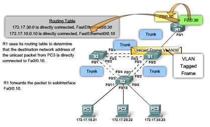
24 Router on a Stick: Routing Table Examine routing table using show ip route command. There are two routes in the routing table. One route is to the subnet, which is attached to the local subinterface F0/0.10. The other route is to the subnet, which is attached to the local subinterface F0/0.30. Verify Router Configuration using the show runningconfig command in privileged EXEC mode. Interface F0/0.10 has been configured correctly with the IP address. The absence of the shutdown command below the F0/0 interface. The absence of the shutdown command confirms that the no shutdown command has been issued and the interface is enabled. You can get more detailed information about the router interfaces, such as diagnostic information, status, MAC address, and transmit or receive errors, using the show interface command in privileged EXEC mode. 24


25 Verify Router on a Stick Inter-VLAN Routing For the example shown in the figure, you would initiate a ping and a tracert from PC1 to the PC3. The Ping Test The ping command sends an ICMP echo request to the destination address. When a host receives an ICMP echo request, it responds with an ICMP echo reply to confirm that it received the ICMP echo request. The Tracert Test Tracert is a utility for confirming the routed path taken between two devices. Tracert also uses ICMP to determine the path taken, but it uses ICMP echo requests with specific time-to-live values defined on the frame. The first ICMP echo request is sent with a time-to-live value set to expire at the first router on route to the destination device. When the ICMP echo request times out on the first route, a confirmation is sent back from the router to the originating device. The device send out another ICMP echo request, but this time with a greater time-to-live value. The process repeats until finally the ICMP echo request is sent all the way to the final destination device. 25

26 Switch Configuration Issues: Topology 1 When using the traditional routing model for inter- VLAN routing, ensure that the switch ports that connect to the router interfaces are configured on the correct VLANs. If the switch ports are not configured on the correct VLAN, devices configured on that VLAN cannot connect to the router interface, and therefore, are unable to route to the other VLANs. As you can see in Topology 1, PC1 and router R1 interface F0/0 are configured to be on the same logical subnet, as indicated by their IP address assignment. However, the switch port F0/4 that connects to router R1 interface F0/0 has not been configured and remains in the default VLAN. Because router R1 is on a different VLAN than PC1, they are unable to communicate. To correct this problem, execute the switchport access vlan 10 interface configuration command on switch port F0/4 on switch S1. 26

27 Switch Configuration Issues: Topology 2 In Topology 2, the router-on-a-stick routing model has been chosen. However, the F0/5 interface on switch S1 is not configured as a trunk and subsequently left in the default VLAN for the port. As a result, the router is not able to function correctly because each of its configured subinterfaces is unable to send or receive VLAN tagged traffic. This prevents all configured VLANs from routing through router R1 to reach the other VLANs. To correct this problem, execute the switchport mode trunk interface configuration command on switch port F0/5 on switch S1. This converts the interface to a trunk, allowing the trunk to successfully establish a connection with router R1. 27

28 Switch Configuration Issues: Topology 3 In Topology 3, the trunk link between switch S1 and switch S2 is down. As a result, all devices connected to switch S2 are unable to route to other VLANs through router R1. To reduce the risk of a failed inter-switch link disrupting inter-vlan routing, redundant links and alternate paths should be configured between switch S1 and switch S2. Redundant links are configured in the form of an EtherChannel that protects against a single link failure. Cisco EtherChannel technology enables you to aggregate multiple physical links into one logical link. (CCNP) Additionally, alternate paths through other interconnected switches could be configured. This approach is dependent on the Spanning Tree Protocol (STP) to prevent the possibility of loops within the switch environment. 28

29 Switch Configuration Issues Incorrect VLAN assignment The screen output shows the results of the show interface interface-id switchport command. Assume that you have issued these commands because you suspect that VLAN 10 has not been assigned to port F0/4 on switch S1. The top highlighted area shows that port F0/4 on switch S1 is in access mode, but it does not show that it has been directly assigned to VLAN 10. The bottom highlighted area confirms that port F0/4 is still set to the default VLAN. 29

30 Switch Configuration Issues Incorrect access mode assignment Communication between R1 and S1 is supposed to be a trunk link. The screen output shows the results of the show interface interface-id switchport and the show running-config commands. The top highlighted area confirms that port F0/4 on switch S1 is in access mode, not trunk mode. The bottom highlighted area also confirms that port F0/4 has been configured for access mode. 30

31 Router Configuration Issues: Topology 1 One of the most common inter-vlan router configuration errors is to connect the physical router interface to the wrong switch port, placing it on the incorrect VLAN and preventing it from reaching the other VLANs. As you can see in Topology 1, router R1 interface F0/0 is connected to switch S1 port F0/9. Switch port F0/9 is configured for Default VLAN, not VLAN10. This prevents PC1 from being able to communicate with the router interface, and it is therefore unable to route to VLAN30. To correct this problem, physically connect router R1 interface F0/0 to switch S1 port F0/4. This puts the router interface on the correct VLAN and allows inter-vlan routing to function. Alternatively, you could change the VLAN assignment of switch port F0/9 to be on VLAN10. This also allows PC1 to communicate with router R1 interface F0/0. 31

32 Router Configuration Issues: Topology 2 In Topology 2, router R1 has been configured to use the wrong VLAN on subinterface F0/0.10, preventing devices configured on VLAN10 from communicating with subinterface F0/0.10. To correct this problem, configure subinterface F0/0.10 to be on the correct VLAN using the encapsulation dot1q 10 subinterface configuration mode command. When the subinterface has been assigned to the correct VLAN, it is accessible by devices on that VLAN and can perform inter-vlan routing. 32

33 Verify Router Configuration Issues In this troubleshooting scenario, you suspect a problem with the router R1. The subinterface F0/0.10 should allow access to VLAN 10 traffic, and the subinterface F0/0.30 should allow VLAN 30 traffic. The screen capture shows the results of running the show interface and the show running-config commands. The top highlighted section shows that the subinterface F0/0.10 on router R1 uses VLAN 100. With proper verification, router configuration problems are quickly addressed, allowing for inter-vlan routing to function again properly. Recall that the VLANs are directly connected, which is how they enter the routing table. 33
34 IP Addressing Issues: Topology 1 For inter-vlan routing to operate,each interface, or subinterface, needs to be assigned an IP address that corresponds to the subnet for which it is connected. As you can see in Topology 1, router R1 has been configured with an incorrect IP address on interface F0/0. To correct this problem, assign the correct IP address to router R1 interface F0/0 using the ip address interface command in configuration mode. After the router interface has been assigned the correct IP address, PC1 can use the interface as a default gateway for accessing other VLANs. 34
35 IP Addressing Issues: Topology 2 In Topology 2, PC1 has been configured with an incorrect IP address for the subnet associated with VLAN10. To correct this problem, assign the correct IP address to PC1. Depending on the type of PC being used, the configuration details may be different. 35

36 IP Addressing Issues: Topology 3 In Topology 3, PC1 has been configured with the incorrect subnet mask. According to the subnet mask configured for PC1, PC1 is on the network. This results in PC1 determining that PC3, with IP address , is on the local subnet. As a result, PC1 does not forward traffic destined for PC3 to router R1 interface F0/0. Therefore, the traffic never reaches PC3. To correct this problem, change the subnet mask on PC1 to Depending on the type of PC being used, the configuration details may be different. 36


37 Verify IP Addressing Issues A common error is to incorrectly configure an IP address for a subinterface. The screen capture shows the results of the show running-config command. The highlighted area shows that the subinterface F 0/0.10 on router R1 has an IP address of The VLAN for this subinterface should allow VLAN 10 traffic. The show ip interface is another useful command. The second highlight shows the incorrect IP address. Sometimes it is the end-user device, such as a personal computer, that is the culprit. In the screen output configuration of the computer PC1, the IP address is , with a subnet mask of But in this scenario, PC1 should be in VLAN10, with an address of and a subnet mask of
38 Summary Inter-VLAN routing is the process of routing information between VLANs Inter-VLAN routing requires the use of a router or a layer 3 switch Tony Chen COD Traditional inter-vlan routing Cisco Networking Academy Requires multiple router interfaces that are each connected to separate VLANs 38
39 Summary Router on a stick this is an inter-vlan routing topology that uses router sub interfaces connected to a layer 2 switch. Each Subinterface must be configured with: An IP address Associated Tony VLAN Chen number COD Cisco Networking Academy Configuration of inter VLAN routing Configure switch ports connected to router with correct VLAN Configure each router subinterface with the correct IP address & VLAN ID Verify configuration on switch and router 39
University of Jordan Faculty of Engineering & Technology Computer Engineering Department Advance Networks Laboratory Exp.4 Inter-VLAN Routing
 University of Jordan Faculty of Engineering & Technology Computer Engineering Department Advance Networks Laboratory 0907529 Exp.4 Inter-VLAN Routing Objectives 1. Describe the three primary options for
Chapter 5: Inter-VLAN Routing. Routing & Switching
 Chapter 5: Inter-VLAN Routing Routing & Switching What is Inter-VLAN routing? Layer 2 switches cannot forward traffic between VLANs without the assistance of a router. Inter-VLAN routing is a process for
Implement VTP. LAN Switching and Wireless Chapter 4 Modified by Tony Chen 10/01/2008
 Implement VTP LAN Switching and Wireless Chapter 4 Modified by Tony Chen 10/01/2008 ITE I Chapter 6 2006 Cisco Systems, Inc. All rights reserved. Cisco Public 1 Notes: If you see any mistake on my PowerPoint
Implement Spanning Tree Protocols-PART-I. LAN Switching and Wireless Chapter 5 Modified by Tony Chen 05/01/2008
 Implement Spanning Tree Protocols-PART-I LAN Switching and Wireless Chapter 5 Modified by Tony Chen 05/01/2008 ITE I Chapter 6 2006 Cisco Systems, Inc. All rights reserved. Cisco Public 1 Notes: If you
Configuring VLANs. Understanding VLANs CHAPTER
 CHAPTER 11 This chapter describes how to configure normal-range VLANs (VLAN IDs 1 to 1005) and extended-range VLANs (VLAN IDs 1006 to 4094) on the Cisco ME 3400 Ethernet Access switch. It includes information
Configuring VLANs. Understanding VLANs CHAPTER
 7 CHAPTER This chapter describes how to configure normal-range VLANs (VLAN IDs 1 to 1005) and extended-range VLANs (VLAN IDs 1006 to 4094) on the Cisco MWR 2941 router. It includes information about VLAN
Lab 6.4.2: Challenge Inter-VLAN Routing
 Lab 6.4.2: Challenge Inter-VLAN Routing Topology Diagram Addressing Table Device (Hostname) Interface IP Address Subnet Mask Default Gateway S1 VLAN 99 192.168.99.11 255.255.255.0 192.168.99.1 S2 VLAN
VLAN Configuration. Understanding VLANs CHAPTER
 CHAPTER 11 This chapter describes how to configure normal-range VLANs (VLAN IDs 1 to 1005) and extended-range VLANs (VLAN IDs 1006 to 4094) on the CGR 2010 ESM. It includes information about VLAN membership
Introduction to Switched Networks Routing And Switching
 Introduction to Switched Networks Routing And Switching 1 Converged Networks Growing Complexity of Networks Our digital world is changing Information must be accessed from anywhere in the world Networks
Lab 7.5.3: Troubleshooting the Wireless WRT300N
 Lab 7.5.3: Troubleshooting the Wireless WRT300N Topology Diagram Addressing Table Device Interface IP Address Subnet Mask Default Gateway Fa0/1.5 5.5.5.10 255.255.255.0 N/A Fa0/1.10 192.168.10.1 255.255.255.0
Configuring VLANs. Understanding VLANs CHAPTER
 CHAPTER 11 This chapter describes how to configure normal-range VLANs (VLAN IDs 1 to 1005) and extended-range VLANs (VLAN IDs 1006 to 4094) on your Catalyst 3550 switch. It includes information about VLAN
Laboration 2 Troubleshooting Switching and First-Hop Redundancy
 Laboration 2 Troubleshooting Switching and First-Hop Redundancy Topology All contents are Copyright 1992 2011 Cisco Systems, Inc. All rights reserved. This document is Cisco Public Information. Page 1
Interconnecting Cisco Networking Devices Part 2 (ICND2 v3.0)
") Interconnecting Cisco Networking Devices Part 2 (ICND2 v3.0) Cisco 200-105 Dumps Available Here at: /cisco-exam/200-105-dumps.html Enrolling now you will get access to 170 questions in a unique set of
Interconnecting Cisco Networking Devices Part 2 (ICND2 v3.0) Cisco 200-105 Dumps Available Here at: /cisco-exam/200-105-dumps.html Enrolling now you will get access to 170 questions in a unique set of
The following steps should be used when configuring a VLAN on the EdgeXOS platform:
 EdgeXOS VLANs VLAN Overview This document provides an overview of what a VLAN is and how it is configured on the EdgeXOS platform. Use the step-by-step guide below to configure a VLAN on the Edge appliance
CCNA Exploration Network Fundamentals
 CCNA Exploration 4.0 1. Network Fundamentals The goal of this course is to introduce you to fundamental networking concepts and technologies. These online course materials will assist you in developing
Lab 1. CLI Navigation. Scenario. Initial Configuration for R1
 Lab 1 CLI Navigation This lab covers the most basic skills for accessing and using the command-line interface (CLI) on a Cisco router or switch. Many of the small, picky details of how the CLI works cannot
Chapter 2. Switch Concepts and Configuration. Part I
 Chapter 2 Switch Concepts and Configuration Part I CCNA3-1 Chapter 2-1 Note for Instructors These presentations are the result of a collaboration among the instructors at St. Clair College in Windsor,
Configuring VLANs. Understanding VLANs CHAPTER
 CHAPTER 9 This chapter describes how to configure normal-range VLANs (VLAN IDs 1 to 1005) and extended-range VLANs (VLAN IDs 1006 to 4094). It includes information about VLAN membership modes, VLAN configuration
Configuring VLANs. Understanding VLANs CHAPTER
 CHAPTER 14 This chapter describes how to configure normal-range VLANs (VLAN IDs 1 to 1005) and extended-range VLANs (VLAN IDs 1006 to 4094) on the Catalyst 3750 switch. It includes information about VLAN
Lab 5: Inter-VLANs Routing
 Lab 5: Inter-VLANs Routing Network Topology:- Device Interface IP Address Subnet Mask Gateway/Clock Rate Fa 0/0.10 10.5.0.1 255.255.255.192 ----- R1 Fa 0/0.20 10.6.0.1 255.255.255.192 ----- Fa 0/0.30 10.10.0.1
Configuring Private VLANs
 CHAPTER 15 This chapter describes how to configure private VLANs on the Cisco 7600 series routers. Note For complete syntax and usage information for the commands used in this chapter, refer to the Cisco
Configuring VLANs. Understanding VLANs CHAPTER
 CHAPTER 12 This chapter describes how to configure normal-range VLANs (VLAN IDs 1 to 1005) and extended-range VLANs (VLAN IDs 1006 to 4094) on the switch. It includes information about VLAN membership
Lab - Troubleshooting VLAN Configurations (Instructor Version Optional Lab)
") (Instructor Version Optional Lab) Instructor Note: Red font color or gray highlights indicate text that appears in the instructor copy only. Optional activities are designed to enhance understanding and/or
(Instructor Version Optional Lab) Instructor Note: Red font color or gray highlights indicate text that appears in the instructor copy only. Optional activities are designed to enhance understanding and/or
et Su cc es s in Passing Yourertification Exam at first
 www.dumpspdf.com in Passing Yourertification Exam at first et Su cc es s Vendor: Cisco Exam Code: 200-101 Exam Name: Interconnecting Cisco Networking Devices Part 2 QUESTION: 1 **Exhibit Missing** A technician
EXAM - HP0-Y52. Applying HP FlexNetwork Fundamentals. Buy Full Product.
 HP EXAM - HP0-Y52 Applying HP FlexNetwork Fundamentals Buy Full Product http://www.examskey.com/hp0-y52.html Examskey HP HP0-Y52 exam demo product is here for you to test the quality of the product. This
Switching & ARP Week 3
 Switching & ARP Week 3 Module : Computer Networks Lecturer: Lucy White lbwhite@wit.ie Office : 324 Many Slides courtesy of Tony Chen 1 Ethernet Using Switches In the last few years, switches have quickly
Top-Down Network Design
 Top-Down Network Design Chapter Seven Selecting Switching and Routing Protocols Original slides by Cisco Press & Priscilla Oppenheimer Selection Criteria for Switching and Routing Protocols Network traffic
Configuring VLANs. Understanding VLANs CHAPTER
 CHAPTER 10 This chapter describes how to configure normal-range VLANs (VLAN IDs 1 to 1005) and extended-range VLANs (VLAN IDs 1006 to 4094) on the switch. It includes information about VLAN membership
Configuring Layer 3 Interfaces
 This chapter contains the following sections: Information About Layer 3 Interfaces, page 1 Licensing Requirements for Layer 3 Interfaces, page 4 Guidelines and Limitations for Layer 3 Interfaces, page
Chapter 5 Lab 5-1 Inter-VLAN Routing INSTRUCTOR VERSION
 CCNPv7.1 SWITCH Chapter 5 Lab 5-1 Inter-VLAN Routing INSTRUCTOR VERSION Topology Objectives Implement a Layer 3 EtherChannel Implement Static Routing Implement Inter-VLAN Routing Background Cisco's switching
Lab Applying a Logical Layered Model to a Physical Network
 Lab 3.1.1 Applying a Logical Layered Model to a Physical Network Objective In this exercise, you will use various Cisco IOS commands and a protocol analyzer to map the layers in the OSI model to the encapsulated
Configuring HSRP. Global Knowledge Training LLC L5-1
 L5 Configuring HSRP Global Knowledge Training LLC L5-1 Objectives In this lab you will examine the hot standby router protocol (HSRP). First you will configure PxR2 similar to PxR1, so they are both possible
Configuring Layer 3 Interfaces
 This chapter contains the following sections: Information About Layer 3 Interfaces, page 1 Licensing Requirements for Layer 3 Interfaces, page 4 Guidelines and Limitations for Layer 3 Interfaces, page
Configuring Access and Trunk Interfaces
 Configuring Access and Trunk Interfaces Ethernet interfaces can be configured either as access ports or trunk ports. Trunks carry the traffic of multiple VLANs over a single link and allow you to extend
Technologies Covered
 Technologies Covered Connect to your POD Base Configuration Interface Configuration Virtual LAN (VLAN) Configuration [Access & Trunk Ports] IP Addressing Frame Relay [Dynamic] RIP Routing TCL Scripts /
Sybex CCENT Chapter 11: VLANs and Inter-VLAN Routing. Instructor & Todd Lammle
 Sybex CCENT 100-101 Chapter 11: VLANs and Inter-VLAN Routing Instructor & Todd Lammle Chapter 11 Objectives The CCENT Topics Covered in this chapter include: LAN Switching Technologies Describe how VLANs
Configuring VLANs. Understanding VLANs CHAPTER
 CHAPTER 16 This chapter describes how to configure normal-range VLANs (VLAN IDs 1 to 1005) and extended-range VLANs (VLAN IDs 1006 to 4094) on your Catalyst 2950 or Catalyst 2955 switch. It includes information
Configuring Interfaces
 CHAPTER 9 This chapter defines the types of interfaces on the Cisco ME 3400 Ethernet Access switch and describes how to configure them. The chapter consists of these sections: Understanding Interface Types,
Configuring Private VLANs
 36 CHAPTER This chapter describes private VLANs (PVLANs) on Catalyst 4500 series switches. It also provides restrictions, procedures, and configuration examples. This chapter includes the following major
CCNA Semester 3 labs. Part 1 of 1 Labs for chapters 1 8
 CCNA Semester 3 labs Part 1 of 1 Labs for chapters 1 8 2.1.2.12 Lab - Building a Switched Network with Redundant Links 2.3.2.3 Lab - Configuring Rapid PVST+, PortFast and BPDU Guard 2.4.3.4 Lab - Configuring
Lab Configuring EtherChannel
 Topology Addressing Table Objectives Device Interface IP Address Subnet Mask S1 VLAN 99 192.168.99.11 255.255.255.0 S2 VLAN 99 192.168.99.12 255.255.255.0 S3 VLAN 99 192.168.99.13 255.255.255.0 PC-A NIC
Configuring HSRP. Understanding HSRP CHAPTER
 CHAPTER 40 This chapter describes how to use Hot Standby Router Protocol (HSRP) on the Cisco ME 3400E Ethernet Access switch to provide routing redundancy for routing IP traffic without being dependent
the larger the number of users and devices, the more broadcasts and packets each switch must handle.
 VLANs Introduction By default, routers allow broadcasts to occur only within the originating network, while switches forward broadcasts to all segments. Flat network = one broadcast domain. that the largest
Configuring Spanning Tree Protocol
 CHAPTER 7 This chapter descibes how to configure Spanning Tree Protocol (STP) on the Cisco wireless mobile interface card (WMIC). Note For complete syntax and usage information for the commands used in
Lab 6-1 Configuring a WLAN Controller
 Lab 6-1 Configuring a WLAN Controller Topology Diagram Scenario In the next two labs, you will configure a wireless solution involving a router with a built-in WLAN controller, two lightweight wireless
Ch. 9 VTP (Trunking, VTP, Inter-VLAN Routing) CCNA 3 version 3.0
 CCNA 3 version 3.0") Ch. 9 VTP (Trunking, VTP, Inter-VLAN Routing) CCNA 3 version 3.0 Overview Explain the origins and functions of VLAN trunking Describe how trunking enables the implementation of VLANs in a large network
Ch. 9 VTP (Trunking, VTP, Inter-VLAN Routing) CCNA 3 version 3.0 Overview Explain the origins and functions of VLAN trunking Describe how trunking enables the implementation of VLANs in a large network
Configuring Interfaces
 CHAPTER 9 This chapter defines the types of interfaces on the Cisco ME 3400 Ethernet Access switch and describes how to configure them. Understanding Interface Types, page 9-1 Using Interface Configuration
CCNA 3 (v v6.0) Chapter 6 Exam Answers % Full
 Chapter 6 Exam Answers % Full") CCNA 3 (v5.0.3 + v6.0) Chapter 6 Exam Answers 2017 100% Full ccnav6.com /ccna-3-v5-0-3-v6-0-chapter-6-exam-answers-2017-100-full.html CCNA Exam Answers 2017 CCNA 3 (v5.0.3 + v6.0) Chapter 6 Exam Answers
CCNA 3 (v5.0.3 + v6.0) Chapter 6 Exam Answers 2017 100% Full ccnav6.com /ccna-3-v5-0-3-v6-0-chapter-6-exam-answers-2017-100-full.html CCNA Exam Answers 2017 CCNA 3 (v5.0.3 + v6.0) Chapter 6 Exam Answers
Using Packet Tracer to Build a Network
 Using Packet Tracer to Build a Network We will be using Packet Tracer today to create the following network. This topology requires one 2811 router two 2960 switches and three workstations. Launch Packet
For information about configuring these settings from Cluster Management Suite (CMS), refer to the online help.
, refer to the online help.") Configuring VLANs This chapter provides information about configuring virtual LANs (VLANs). It includes command-line interface (CLI) procedures for using commands that have been specifically created or
Configuring VLANs This chapter provides information about configuring virtual LANs (VLANs). It includes command-line interface (CLI) procedures for using commands that have been specifically created or
CCNA Cisco Certified Network Associate CCNA (v3.0)
") CCNA Cisco Certified Network Associate CCNA (v3.0) Cisco 200-125 Dumps Available Here at: /cisco-exam/200-125-dumps.html Enrolling now you will get access to 455 questions in a unique set of 200-125 dumps
CCNA Cisco Certified Network Associate CCNA (v3.0) Cisco 200-125 Dumps Available Here at: /cisco-exam/200-125-dumps.html Enrolling now you will get access to 455 questions in a unique set of 200-125 dumps
Configuring SPAN and RSPAN
 34 CHAPTER This chapter describes how to configure the Switched Port Analyzer (SPAN) and Remote SPAN (RSPAN) on the Catalyst 4500 series switches. SPAN selects network traffic for analysis by a network
VLANs. LAN Switching and Wireless Chapter 3. Version Cisco Systems, Inc. All rights reserved. Cisco Public 1
 VLANs LAN Switching and Wireless Chapter 3 Version 4.0 2006 Cisco Systems, Inc. All rights reserved. Cisco Public 1 Objectives Explain the role of VLANs in a converged network. Explain the role of trunking
Configuring VLANs. Finding Feature Information. Prerequisites for VLANs
 Finding Feature Information, page 1 Prerequisites for VLANs, page 1 Restrictions for VLANs, page 2 Information About VLANs, page 2 How to Configure VLANs, page 7 Monitoring VLANs, page 19 Where to Go Next,
Which of the following are primary functions of a router? (Choose two.) - packet switching - path selection
 - packet switching - path selection") Which three statements are true regarding the encapsulation and de-encapsulation of packets when traveling through a router? (Choose three.) - The router modifies the TTL field, decrementing it by one.
Which three statements are true regarding the encapsulation and de-encapsulation of packets when traveling through a router? (Choose three.) - The router modifies the TTL field, decrementing it by one.
Configuring VLANs. Understanding VLANs CHAPTER
 CHAPTER 14 This chapter describes how to configure normal-range VLANs (VLAN IDs 1 to 1005) and extended-range VLANs (VLAN IDs 1006 to 4094). It includes information about VLAN modes and the VLAN Membership
exam. Number: Passing Score: 800 Time Limit: 120 min CISCO Interconnecting Cisco Networking Devices Part 1 (ICND)
") 100-105.exam Number: 100-105 Passing Score: 800 Time Limit: 120 min CISCO 100-105 Interconnecting Cisco Networking Devices Part 1 (ICND) Exam A QUESTION 1 Which route source code represents the routing
100-105.exam Number: 100-105 Passing Score: 800 Time Limit: 120 min CISCO 100-105 Interconnecting Cisco Networking Devices Part 1 (ICND) Exam A QUESTION 1 Which route source code represents the routing
Implementing Inter-VLAN Routing. 2003, Cisco Systems, Inc. All rights reserved. 2-1
 Implementing Inter-VLAN Routing 2003, Cisco Systems, Inc. All rights reserved. 2-1 Internetwork Communications C:>ping 172.16.30.100 Can two hosts on different subnets communicate without a router? No
FSOS. Ethernet Configuration Guide
 FSOS Ethernet Configuration Guide Contents 1 Configuring Interface... 1 1.1 Overview...1 1.2 Configuring Interface State...1 1.2.1 Configurations...1 1.2.2 Validation...1 1.3 Configuring Interface Speed...
Cisco Questions & Answers
 Cisco 200-101 Questions & Answers Number: 200-101 Passing Score: 800 Time Limit: 120 min File Version: 23.7 http://www.gratisexam.com/ Cisco 200-101 Questions & Answers Exam Name: Interconnecting Cisco
Configuring Interface Characteristics
 CHAPTER 10 This chapter defines the types of interfaces on the switch and describes how to configure them. Unless otherwise noted, the term switch refers to a standalone switch and to a switch stack. The
Lab Subnetting Network Topologies (Instructor Version)
") (Instructor Version) Instructor Note: Red font color or Gray highlights indicate text that appears in the instructor copy only. Objectives Parts 1 to 5, for each network topology: Determine the number
(Instructor Version) Instructor Note: Red font color or Gray highlights indicate text that appears in the instructor copy only. Objectives Parts 1 to 5, for each network topology: Determine the number
Configuring Private Hosts
 CHAPTER 25 This chapter describes how to configure the private hosts feature in Cisco IOS Release 12.2SX. Note For complete syntax and usage information for the commands used in this chapter, see the Cisco
Lab Configuring 802.1Q Trunk-Based Inter-VLAN Routing Topology
 Topology 2016 Cisco and/or its affiliates. All rights reserved. This document is Cisco Public. Page 1 of 7 Addressing Table Device Interface IP Address Subnet Mask Default Gateway R1 G0/1.1 192.168.1.1
LAN design. Chapter 1
 LAN design Chapter 1 1 Topics Networks and business needs The 3-level hierarchical network design model Including voice and video over IP in the design Devices at each layer of the hierarchy Cisco switches
Describing the STP. Enhancements to STP. Configuring PortFast. Describing PortFast. Configuring. Verifying
 Enhancements to STP Describing the STP PortFast Per VLAN Spanning Tree+ (PVST+) Rapid Spanning Tree Protocol (RSTP) Multiple Spanning Tree Protocol (MSTP) MSTP is also known as Multi-Instance Spanning
Objectives. 1. Introduction:
 University of Jordan Faculty of Engineering & Technology Computer Engineering Department Advance Networks Laboratory 0907529 Exp.5 Spanning-Tree Protocol (STP) Objectives 1. Explain the role of redundancy
VLANs Level 3 Unit 9 Computer Networks
 VLANs Some Requirements of LANs Need to split up broadcast domains to make good use of bandwidth People in different departments may need to be grouped together for access to servers Security: restrict
Pass-Through Technology
 CHAPTER 3 This chapter provides best design practices for deploying blade servers using pass-through technology within the Cisco Data Center Networking Architecture, describes blade server architecture,
Vendor: Cisco. Exam Code: Exam Name: Cisco Interconnecting Cisco Networking Devices Part 1 (ICND1 v3.0) Version: Demo
 Version: Demo") Vendor: Cisco Exam Code: 100-105 Exam Name: Cisco Interconnecting Cisco Networking Devices Part 1 (ICND1 v3.0) Version: Demo DEMO QUESTION 1 If the resume command is entered after the sequence that is
Vendor: Cisco Exam Code: 100-105 Exam Name: Cisco Interconnecting Cisco Networking Devices Part 1 (ICND1 v3.0) Version: Demo DEMO QUESTION 1 If the resume command is entered after the sequence that is
Lab : Challenge OSPF Configuration Lab. Topology Diagram. Addressing Table. Default Gateway. Device Interface IP Address Subnet Mask
 Topology Diagram Addressing Table Device Interface IP Address Subnet Mask Default Gateway Fa0/0 HQ S0/0/0 S0/0/1 Lo1 10.10.10.1 255.255.255.252 Fa0/0 Branch1 S0/0/0 S0/0/1 Fa0/0 Branch2 S0/0/0 S0/0/1 PC1
CCNA Cisco Certified Network Associate CCNA (v3.0)
") 200-125 - CCNA Cisco Certified Network Associate CCNA (v3.0) 1.What is one benefit of PVST+? A. PVST+ supports Layer 3 load balancing without loops. B. PVST+ reduces the CPU cycles for all the switches
200-125 - CCNA Cisco Certified Network Associate CCNA (v3.0) 1.What is one benefit of PVST+? A. PVST+ supports Layer 3 load balancing without loops. B. PVST+ reduces the CPU cycles for all the switches
Packet Tracer - Connect a Router to a LAN (Instructor Version)
") (Instructor Version) Instructor Note: Red font color or gray highlights indicate text that appears in the instructor copy only. Topology Addressing Table Device Interface IP Address Subnet Mask Default
(Instructor Version) Instructor Note: Red font color or gray highlights indicate text that appears in the instructor copy only. Topology Addressing Table Device Interface IP Address Subnet Mask Default
Introduction to the Packet Tracer Interface using a Hub Topology
 Introduction to Packet Tracer What is Packet Tracer? Packet Tracer is a protocol simulator developed by Dennis Frezzo and his team at Cisco Systems. Packet Tracer (PT) is a powerful and dynamic tool that
CCNA Semester 3 labs. Labs for chapters 2 10
 CCNA Semester 3 labs Labs for chapters 2 10 2.1.4.5 Lab - Configure Extended VLANs, VTP, and DTP 2.2.2.5 Lab - Troubleshooting Inter-VLAN Routing 3.1.2.12 Lab - Building a Switched Network with Redundant
Configuring Private VLANs
 Finding Feature Information, on page 1 Prerequisites for Private VLANs, on page 1 Restrictions for Private VLANs, on page 1 Information About Private VLANs, on page 2 How to Configure Private VLANs, on
Configuring VLANs. Understanding VLANs
 This document describes how to configure your Cisco wireless mobile interface card (WMIC) to operate with the VLANs set up on your wired LAN. These sections describe how to configure your WMIC to support
Configuring Link Aggregation
 Information About Link Aggregation, page 1 Restrictions for Link Aggregation, page 1 (GUI), page 3 (CLI), page 4 Verifying Link Aggregation Settings (CLI), page 4 Configuring Neighbor Devices to Support
Configuring VLAN Trunks
 Finding Feature Information, page 1 Prerequisites for VLAN Trunks, page 1 Information About VLAN Trunks, page 2 How to Configure VLAN Trunks, page 5 Configuration Examples for VLAN Trunking, page 20 Where
Lab 6-1 Configuring a WLAN Controller
 Lab 6-1 Configuring a WLAN Controller Topology Diagram Scenario In the next two labs, you will configure a wireless solution involving a WLAN controller, two lightweight wireless access points, and a switched
Actual4Test. Actual4test - actual test exam dumps-pass for IT exams
 Actual4Test http://www.actual4test.com Actual4test - actual test exam dumps-pass for IT exams Exam : 200-125 Title : CCNA Cisco Certified Network Associate CCNA (v3.0) Vendor : Cisco Version : DEMO Get
Configuring VLANs. Finding Feature Information. Prerequisites for VLANs
 Finding Feature Information, page 1 Prerequisites for VLANs, page 1 Restrictions for VLANs, page 2 Information About VLANs, page 2 How to Configure VLANs, page 8 Monitoring VLANs, page 22 Where to Go Next,
Switches running the LAN Base feature set support only static routing on SVIs.
 Finding Feature Information, on page 1 Prerequisites for VLANs, on page 1 Restrictions for VLANs, on page 2 Information About VLANs, on page 2 How to Configure VLANs, on page 6 Monitoring VLANs, on page
Lab 5-1 Hot Standby Router Protocol
 Lab 5-1 Hot Standby Router Protocol Topology Diagram Objective Configure inter-vlan routing with HSRP to provide redundant, fault tolerant routing to the internal network. Scenario Step 1 HSRP provides
Lab 3.3 Configuring Wireshark and SPAN
 Lab 3.3 Configuring Wireshark and SPAN Learning Objectives Install Wireshark on a host PC Configure a switch to use the SPAN monitoring tool. Topology Diagram Scenario In this lab, you will configure a
CISCO EXAM QUESTIONS & ANSWERS
 CISCO 200-101 EXAM QUESTIONS & ANSWERS Number: 200-101 Passing Score: 800 Time Limit: 120 min File Version: 32.2 http://www.gratisexam.com/ CISCO 200-101 EXAM QUESTIONS & ANSWERS Exam Name: Interconnecting
3. What could you use if you wanted to reduce unnecessary broadcast, multicast, and flooded unicast packets?
 Nguyen The Nhat - Take Exam Exam questions Time remaining: 00: 00: 51 1. Which command will give the user TECH privileged-mode access after authentication with the server? username name privilege level
RealCiscoLAB.com. Configuring EtherChannel. Topology. Objective. Background. Required Resources. CCNPv6 Switch. Configure EtherChannel.
 RealCiscoLAB.com CCNPv6 Switch Configuring EtherChannel Topology Objective Background Configure EtherChannel. Four switches have just been installed. The distribution layer switches are Catalyst 3560 switches,
Antonio Cianfrani. Virtual LAN (VLAN)
") Antonio Cianfrani Virtual LAN (VLAN) Ethernet Ethernet standard (IEEE 802.3) for Local Area Network (LAN). CSMA/CD (Carrier Sense Multiple Access/Collision Detection) Carrier Sense: all devices have to
Antonio Cianfrani Virtual LAN (VLAN) Ethernet Ethernet standard (IEEE 802.3) for Local Area Network (LAN). CSMA/CD (Carrier Sense Multiple Access/Collision Detection) Carrier Sense: all devices have to
CCENT Study Guide. Chapter 11 VLANs and Inter-VLAN Routing
 CCENT Study Guide Chapter 11 VLANs and Inter-VLAN Routing Chapter 11 Objectives The CCENT Topics Covered in this chapter include: 2.0 LAN Switching Technologies 2.4 Configure, verify, and troubleshoot
Implementing Inter-VLAN Routing
 Internetwork Communications C:>ping 72.6.30.00 Implementing Inter-VLN Routing Can two hosts on different subnets communicate without a router? No What would happen if a host tried to ping another host?
VLANs over IP Unnumbered SubInterfaces
 The VLANs over IP Unnumbered Subinterfaces feature allows IP unnumbered interface support to be configured on Ethernet VLAN subinterfaces. This feature also provides support for DHCP on VLAN subinterfaces.
Skills Assessment (OSPF) Student Training Exam
 Student Training Exam") Skills Assessment (OSPF) Student Training Exam Topology 2013 Cisco and/or its affiliates. All rights reserved. This document is Cisco Public. Page 1 of 17 Addressing Table Assessment Objectives Device
Skills Assessment (OSPF) Student Training Exam Topology 2013 Cisco and/or its affiliates. All rights reserved. This document is Cisco Public. Page 1 of 17 Addressing Table Assessment Objectives Device
VLANs. Traditional Campus Networks. Performance Issues. Broadcast Issues. Bridges terminate collision domains
 Traditional Campus Networks Broadcast Domain VLANs Collision Domain 1 Collision Domain 2 Bridges terminate collision domains 2003, Cisco Systems, Inc. All rights reserved. 2-1 2003, Cisco Systems, Inc.
VLANs. 2003, Cisco Systems, Inc. All rights reserved. 2-1
 VLANs 2003, Cisco Systems, Inc. All rights reserved. 2-1 Traditional Campus Networks Broadcast Domain Collision Domain 1 Collision Domain 2 Bridges terminate collision domains 2003, Cisco Systems, Inc.
CISCO EXAM QUESTIONS & ANSWERS
 CISCO 100-101 EXAM QUESTIONS & ANSWERS Number: 100-101 Passing Score: 800 Time Limit: 120 min File Version: 35.5 http://www.gratisexam.com/ CISCO 100-101 EXAM QUESTIONS & ANSWERS Exam Name: CCNA Interconnecting
VLANs. 2003, Cisco Systems, Inc. All rights reserved. 2-1
 VLANs 2003, Cisco Systems, Inc. All rights reserved. 2-1 Traditional Campus Networks Broadcast Domain Collision Domain 1 Collision Domain 2 Bridges terminate collision domains 2003, Cisco Systems, Inc.
Chapter 5. RIP Version 1 (RIPv1)
") Chapter 5 RIP Version 1 (RIPv1) CCNA2-1 Chapter 5 Note for Instructors These presentations are the result of a collaboration among the instructors at St. Clair College in Windsor, Ontario. Thanks must
Chapter 5 RIP Version 1 (RIPv1) CCNA2-1 Chapter 5 Note for Instructors These presentations are the result of a collaboration among the instructors at St. Clair College in Windsor, Ontario. Thanks must
Configuring SPAN and RSPAN
 41 CHAPTER This chapter describes how to configure the Switched Port Analyzer (SPAN) and Remote SPAN (RSPAN) on the Catalyst 4500 series switches. SPAN selects network traffic for analysis by a network
Laboration 1 Examine the Topology and Basic Troubleshooting Commands
 Laboration 1 Examine the Topology and Basic Troubleshooting Commands Topology All contents are Copyright 1992 2011 Cisco Systems, Inc. All rights reserved. This document is Cisco Public Information. Page