DAC Installation & Tuning Manual 2015
|
|
|
- Diane Goodwin
- 5 years ago
- Views:
Transcription

1 DAC Installation & Tuning Manual 2015 Effective March 1, 2015 Rust Sales, Inc. 2015
2 Disclaimer and Limited Warranty Statement While every effort has been made to ensure the accuracy of this document, Rust Sales, Inc. assumes no responsibility for omissions or errors. Nor is any liability assumed for damages resulting from the use of information contained in this manual. 2 Rust Sales, Inc. shall not be responsible or liable for incidental or consequential damages; or a loss of anticipated benefits or profits; or work stoppage; or loss or impairment of data arising out of the use, or inability to use the control software or computer or any other components. Rust Sales, Inc. warrants each product that it manufactures to be free from defects in material and workmanship. This warranty is applicable only for the normal service life expectancy of the product or components, not to exceed 12 consecutive months from the date of the delivery to the original purchaser. This warranty coverage applies only to the original owner and is not transferable. Under no circumstances will it cover any merchandise or components thereof, which in the opinion of the company has been subject to misuse, unauthorized modification, alterations, improper installation, maintenance, an accident or if repairs have been made with parts other than those obtained through Rust Sales, Inc. Our obligation under this warranty shall be limited to repairing at our facility or replacing, free of charge to the original purchaser, any part that, in our judgment, shall show evidence of such defect, provided further that such part be returned within 30 days from the date of failure to Rust Sales, Inc. routed through the dealer from whom the purchase was made, transportation charges prepaid. Proof of purchase must also accompany the returning defective part. This warranty shall not be interpreted to render Rust Sales, Inc. liable for injury or damages of any kind or nature to person or property. This warranty does not extend to the loss of revenue, extra labor cost associated with downtime, substitute machinery, rental, or for any other reason. Except as set forth above, Rust Sales, Inc. shall have no obligation or liability of any kind on account of any of its equipment and shall not be liable for special or consequential damages. Rust Sales, Inc. makes no other warranty, express or implied, and specifically, Rust Sales, Inc. disclaims any implied warrant or merchantability or fitness for a particular purpose. Some states or provinces do not permit limitations or exclusions of implied warranties or incidental or consequential damages, so the limitations or exclusions in this warranty may not apply. This warranty is subject to any existing conditions of supply which may directly affect our ability to obtain materials or manufacture replacement parts. No one is authorized to alter, modify or enlarge this warranty nor the exclusion, limitations, and reservations. As with all wireless and satellite signals, several factors may affect the availability and accuracy of wireless and satellite navigation and correction services. Therefore Rust Sales, Inc. cannot guarantee the accuracy, integrity, continuity, or availability of these services and cannot guarantee the ability to use Rust Sales, Inc. systems or products used as components of the systems, which rely upon the reception of these signals or availability of these services. Rust Sales, Inc. Accepts no responsibility for the use of any of these signals or services for other than the stated purpose.
3 Safety 3 Safety Precaution-Remember, YOU are ultimately responsible for your safety and the safety of those around you! When working with or near these systems, please observe the following safety measures: Be alert and aware of surroundings. Do not operate machinery or systems under the influence of alcohol or an illegal substance. Remain in the operator s position and be in complete control at all times when systems are engaged. Determine and maintain a safe working distance from other machinery, equipment, obstacles, farm personnel, and people. The operator is responsible for proper disengagement of all systems once safe working distance has been determined. Know your software!! The DAC will only move as is called for by a controller package. The operator is required to know how his software package functions and when it could possibly send movement commands to the DAC controller. Hydraulic Safety Requirements Machine must be off, isolated, and stationary while installation and maintenance is being performed. When disconnecting hydraulic hoses, be aware that the hydraulic oil within the system may be hot and under high pressure. Caution must be exercised. Any work carried out on the hydraulic systems must be performed in accordance with the equipment manufacturer s approved maintenance instructions. Rust Sales, Inc. recommends that appropriate protective equipment be worn while working on the hydraulic system. Warning: It is imperative that all hydraulic hoses are connected to the relevant components. Failure to connect the hydraulic hoses correctly will cause damage to the system. Electrical Safety Requirements Do not reverse the power leads. Doing so will cause severe damage to the equipment. Always check to make sure the power leads are connected to the correct polarity. Ensure that the power cable is the last cable to be connected.
4 Contents 4 Introduction Disclaimer... 2 Safety... 3 Contents... 4 Wiring Diagrams John Deere GPS Wiring Diagrams Trimble GPS Wiring Diagrams G2 GPS Wiring Diagrams DAC Mini Wiring Diagram Hardware Installation Mounting the Computer Power and Cables Mounting the GPS Antenna Slope Definitions DAC 7000 Setup within SD Drain DAC 7000 Selection DAC 7000 Configuration DAC Configuration Utility DAC 7000 Configuration DAC 7000 Basic Tuning DAC 7000 Advanced Tuning DAC 7000 Machine Label DAC Unlock Key DAC 2X Setup DAC 2X: Mounting the Sensor DAC 2X Channel 2 Configuration DAC Data Multi-Function Joystick DAC 7000 Pinout Contact Us... 30

5 Wiring Diagrams 5 Wiring Diagrams John Deere GPS
6 Wiring Diagrams 6 Wiring Diagrams John Deere GPS


7 Wiring Diagrams 7 Wiring Diagrams Trimble GPS

8 Wiring Diagrams 8 Wiring Diagrams Trimble GPS


9 Wiring Diagrams 9 Wiring Diagrams 300G2 GPS

10 Wiring Diagrams 10 Wiring Diagrams 300G2 GPS


11 Wiring Diagrams 11

12 Hardware Installation 12 Mounting the Computer Mounting the Computer Picking an ideal position for the computer screen A bar or bracket across the window or side panel of the passenger side of the tractor when seated in the cab is ideal. Use provided ram mounts to connect to the bar or bracket. Drill holes and use bolts if necessary. Make sure there is easy access to the touch screen at all times and that the operator can see the computer at all times. Make sure it is secure as it will take a lot of vibration and bumps during operation. See Picture 11.1 for a generic placement of the computer screen. Picture 11.1: computer screen placement


13 Hardware Installation 13 Power and Cables Power: Most tractors have convenience ports; this is the easiest place to connect the control computer, DAC 7000, and GPS power. Convenience ports: Pictures John Deere has convenience ports on the right hand side of the tractor on the dash by the back right post. Picture CNH has convenience ports on either the front right corner post or behind the seat on the right side (both work well, just depends on how you want the cords to run). Pictures 12.2a and 12.2b. CAT Challenger - Tracked - Challenger A/B has convenience ports behind the seat on the right side. Picture Challenger C/D/E may need an adapter cable from the power strip to a convenience port. If your tractor does not have a convenience port, you should find both constant power and switched and bring that into the cab, and wire in an in-line fuse (10 amp). Picture 12.1: John Deere Picture 12.2a: CNH Picture 12.2b: CNH Picture 12.3: Challenger A/B

 is for GPS ALWAYS (green) COM 2 or COM3 (serial) are for the electronic over hydraulic controller (DAC 7000).")
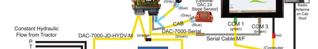
14 Hardware Installation 14 Power and Cables Cables: Routing overview: Run the GPS cables and the electric over hydraulic control cables out of the cab. John Deere out the back window through the rubber seals CNH - out the bottom of the cab; under the right side through the rubber or foam; or out the back window. CAT out the back window through the rubber seals Make sure all cords are tied up and excess is not in a position to get caught on anything or kicked by the operator s feet. Control computer: COM 1 (serial) is for GPS ALWAYS (green) COM 2 or COM3 (serial) are for the electronic over hydraulic controller (DAC 7000). Typically COM 2 on Sailor and COM 3 on AFL2-12A (brown, see starting page 18). See wiring diagrams on pages 5-10 for complete cable hookups. John Deere-00-R Series: For the electronic over hydraulic control cable (DAC-7000-JD), the gray connector off the DAC 7000 will run outside through the back window. Remove the back panel that the slow moving vehicle sign is attached to. The connection will be made underneath that panel on the left side when looking toward the front of the tractor. Make sure the tractor isn't running when plugging the cord in or it will throw a code in the tractor. When it is plugged in and the key is on, the tractor should show EC (or Auto on R Series) on the hydraulic screen showing that the cord has been plugged in. See Pictures 13.1, and 13.2 for examples. Picture 13.1: Remove dust cap from JD connector Picture 13.2: Plug DAC cable into JD connector

.")

 is also needed to give SD Drain control of the")
 button on the corner post, turn the key one notch to the right, then use the arrows to")

15 Hardware Installation 15 Power and Cables CNH for the electronic over hydraulic control cord (DAC-7000-CIH/NH), the gray connector will come off the DAC 7000 and run outside either down underneath the cab on the right side or out the back window. On the MX Series, the connection is under the slow moving vehicle sign. On 2010 and older QuadTracs, the connection is hanging below the cab on the right side (when looking from the back of the cab). See Picture 14.1 (just to the right of the arrow). On the 2011 QuadTrac and newer, the connector is inside the cab under the plastic on the right hand side. See Pictures 14.2a, 14.2b, and 14.2c. A 1-3 switch (must be installed by a CNH dealer, contact your local dealer) is also needed to give SD Drain control of the machine (see Pictures 14.3a and 14.3b). The tractor will now need to be programed to Scraper 1 on the corner post. With the key Off, hold the Program (PROG) button on the corner post, turn the key one notch to the right, then use the arrows to go down to AUX. Hit PROG button, then arrow down to AUX Setup, hit the PROG button, arrow down to Scraper 1 (unless you have a slope sensor, then use Scraper 2). Hit PROG button, then arrow down to AUX Exit, then hit PROG button. Arrow down to EXIT, then hit PROG button. Turn key to OFF. Picture 14.1: QuadTrac 2010 or older: connector Picture 14.2a: QuadTrac 2011 or newer: Picture 14.2b: QuadTrac 2011 or newer: Picture 14.3a: QuadTrac 2010 or older: Picture 14.3b: QuadTrac 2011 or newer: Standard 1-3 switch Picture 14.2c: QuadTrac 2011 or newer:


. Pictures 15.1-15.2.")


16 Hardware Installation 16 Power and Cables Challenger A/B will need to be run outside through the back window and down to the hydraulic block. It is best to use Hydraulic #1, but 1-4 can be used. Numbers 5 and above do not work. Disconnect the connections and reconnect the new ones (note or label which ones they are so they don t get mixed up). Pictures Picture 15.1: CAT hydraulic block Picture 15.2: CAT plugged in Challenger C/D: DAC 7000 controls plug in behind the fuse panel inside the cab, by the floor. Hydraulics #1 and #2 will be able to be controlled. Hydraulic #1 if only one is used. The CAN connector will connect to the Canbus extension cable on the right side of the fuse panel. The connection will be a black 4-pin connector. After the tractor is started, the enablement of the isobus control may be needed (Picture 15.3 and 15.4). Picture 15.3 Picture 15.4 To enable controls, select the wrench button on the main tractor screen (Picture 15.5). Select the second page button (bottom right) (Picture 15.6). Make sure Isobus Class 3 is enabled (Picture 15.7). The end result should be Picture Picture 15.5 Picture 15.6 Picture 15.7 Picture 15.8


17 Hardware Installation 17 Power and Cables Picture 16.1: External Valve control Picture 16.2: Multi-Function Joystick External Valve controls (Picture 16.1) will need to be run from the DAC 7000 to the outside of the cab and run to where the external valve is mounted. This cable needs to be tied up well so that the cable doesn t hang. Multi-Function Joystick - Run the joystick (Picture 16.2) from the DAC 7000 making sure the cables don t get caught or pinched under the seat.


18 Hardware Installation 18 Mounting the GPS Antenna Mounting the GPS Antenna The GPS antenna needs to be mounted directly above the scraper blade or plow tip. It should move 1:1 with the blade or tip. It should be mounted high enough to acquire signal above the tractor (3-6 foot mast is recommended). Scraper: Picture Tile Plow: Picture Make sure the GPS cord running back to the tractor from the antenna is attached securely and not hanging loose. Check that there is enough slack in the line for the movement of the implement and turning of the tractor. Picture 17.1: Scraper mount Slope Definitions Figure Picture 17.2: Tile Pro Tile Plow mount Figure 17.3: Cross Slope Figure 17.4: Fore Slope example


19 DAC 7000 Setup within SD Drain 19 DAC 7000 Setup within SD Drain DAC 7000 Figure 18.1 Choosing the DAC 7000 for control is needed. In SD Drain, go to the Settings Menu, then the DAC Menu, and select Detect. This allows the DAC 7000 to control the hydraulics. DAC 2X (Figure 18.2), refer also to Pages Figure 18.1: DAC 7000 Figure 18.2: DAC 2X DAC 7000 Selection (within SD Drain ) Select Settings Menu Select DAC Menu Select DAC Device Select Detect and the COM port should automatically detect the COM port the DAC 7000 is on.


20 DAC 7000 Setup within SD Drain 20 Select Settings Menu DAC 7000 Configuration Select DAC Menu Select DAC Device Menu Select Open DAC Settings


21 DAC 7000 Configuration Utility 21 DAC 7000 Configuration Choose Setup DAC 7000 Main Configuration window will appear Select COM Select Com Port Select Test Connection to DAC 7000, then verify connection Select Save

22 DAC 7000 Configuration Utility 22 DAC 7000 Configuration Choose the vehicle or external valve type Upload Config to DAC 7000 Save changes to DAC 7000 Machine Control will be saved and it is ready for a test run Your Hydraulic Flow should be set at 60-65%


23 DAC 7000 Configuration Utility 23 DAC 7000 Basic Tuning Minimum Up movement Settings Position blade so it can be moved up or down Move the + slider until the blade starts to come up a minimal amount The least possible movement will help the DAC 7000 be most accurate Minimum Down movement Settings Position blade so it can be moved up or down Move the - slider until the blade starts to move down a minimal amount The least possible movement will help the DAC 7000 be most accurate To save minimum movement settings: Touch the decimal number on the top side of the slider The number will be moved in the tune movement boxes Touch Set Tune then Save changes to DAC7000

24 DAC 7000 Configuration Utility 24 DAC 7000 Advanced Tuning Under Channel-Tune: the more steps there are, the slower the + or will react. (Change these only after the minimum movement is done). If changes need to be made, change one side of the steps and select Set Tune to save changes. Contact your Dealer for advanced tuning assistance. DAC 7000 Configuration After all changes have been made, click Save changes to DAC7000, then exit out of the window.

 Select the Config for Main List.")


25 DAC 7000 Configuration Utility 25 DAC 7000 Machine Label Select Config Admin Select Retrieve Current DAC7000 Config Insert a Config Name (label) Select the Config for Main List. It will appear in the vehicle list. Select Save Config to File DAC Unlock Key Select the Unlock key Select Refresh Feature List to see current unlocks. Enter DAC Unlock Key is for adding unlocks to the DAC when purchased.
 Picture 24.")
, which connects to the slope sensor (DAC 2X) and the On Plow cable.")

26 DAC 2X Setup 26 DAC 2X: Mounting the Sensor Per instructions on DAC 2X decal, place sensor label side up, with arrow pointing forward. Bolts are preferred over Tek screws. Picture 24.1: Liebrecht plow (arrow pointing forward) Picture 24.2: Tile Pro tile plow (arrow pointing forward) Picture 24.3: Gold Digger plow (arrow pointing forward) There are 3 cables. One is a black cable (5P-SLOPE-6P), which connects to the slope sensor (DAC 2X) and the On Plow cable. One is labeled On Plow, which connects at the hitch and connects to the black cable attached to the slope sensor (DAC 2X). The 3 rd cable is labeled In Cab, which connects to the On Plow cable and the DAC 7000 (off DAC 7000 black connector, attach to blue connector labeled CAN, and attach to gray connector labeled Joystick ).


27 DAC 2X Setup 27 DAC 2X Channel 2 Configuration NOTE: When using the DAC 2X, you must also configure Channel 2, and repeat the steps on Pages that outline configuring Channel 1. To Zero DAC 2X, touch the Zero Fore Slope button or Zero Cross Slope button. DAC Data This screen will show information on what the DAC 7000 is reading from the DAC 2X in SD Drain.


28 Multi-Function Joystick 28 DAC Joystick Configuration Select Menu, Device Menu, and Run DACCFG utility Setup DAC 7000 Select: Enable CAN Joystick if using Multi-Function Joystick Enable Analog Joystick if using the 3-Button Joystick Upload Config to DAC7000 and Save changes to DAC7000 If you reload default vehicle configuration, you will need to re-enable the joystick. Changing Settings on the Multi-Function Joystick Select Multi-Function Joystick on the maximized screen of DAC 7000 Config. Select Poll From DAC to see current config. Make changes, then select Save to DAC and exit.

29 DAC 7000 Pinout 29 DAC 7000 Pinout
")
30 Contact Us 30 Contact Us: Rust Sales, Inc th Ave. SE. Harwood, ND Phone: Toll Free: Fax: Hours: Monday Friday 8:00 am 5:00 pm Saturdays 8:00 am 12 Noon (Apr Nov) Closed Sundays and Holidays After Hours Tech Support: Chris Follow Us:
INSTALLATION MANUAL. Agra-GPS CNH-JD Bridge for a Quadtrac (can based steering)
") INSTALLATION MANUAL Agra-GPS CNH-JD Bridge for a Quadtrac (can based steering) Version 1.0 Revision A April 2018 Contact information Agra-GPS Ltd. Box 2585 Stony Plain, AB T7Z 1X9 CANADA 001 780 990 4052
INSTALLATION MANUAL Agra-GPS CNH-JD Bridge for a Quadtrac (can based steering) Version 1.0 Revision A April 2018 Contact information Agra-GPS Ltd. Box 2585 Stony Plain, AB T7Z 1X9 CANADA 001 780 990 4052
Installation and Operation Guide
 Installation and Operation Guide Raven Switch Box for Use with ISObus Systems Disclaimer While every effort has been made to ensure the accuracy of this document, Raven Industries assumes no responsibility
INSTALLATION MANUAL. Agra-GPS Versatile-JD Bridge (row crop tractor)
") INSTALLATION MANUAL Agra-GPS Versatile-JD Bridge (row crop tractor) Version 1.0 Revision A December 2017 Contact information Agra-GPS Ltd. Box 2585 Stony Plain, AB T7Z 1X9 CANADA 001 780 990 4052 Phone
INSTALLATION MANUAL Agra-GPS Versatile-JD Bridge (row crop tractor) Version 1.0 Revision A December 2017 Contact information Agra-GPS Ltd. Box 2585 Stony Plain, AB T7Z 1X9 CANADA 001 780 990 4052 Phone
INSTALLATION MANUAL. Agra-GPS Versatile-JD Bridge
 INSTALLATION MANUAL Agra-GPS Versatile-JD Bridge Version 1.0 Revision A September 2017 Contact information Agra-GPS Ltd. Box 2585 Stony Plain, AB T7Z 1X9 CANADA 001 780 990 4052 Phone www.agra-gps.com
SP-C1 Mobile Docking Station Installation Guide
 SP-C1 Mobile Docking Station Installation Guide Box Contents After you unpack your SP-C1 Mobile Docking Station, make sure everything here is included: 1 x Docking Cradle 1 x Audio Cable 1 x Adhesive Mount
AGRI-COVERTM REMOTE CONTROL INSTRUCTIONS
 AGRI-COVERTM REMOTE CONTROL INSTRUCTIONS Use these instructions to install and operate remote control with AGRI-COVERTM Switch Control. Read and follow these instructions along with the installation instructions
Hi-Tech Transport Electronics, Inc. DUAL LEVELING VALVE PROCESSOR INSTALLATION MANUAL. For the 4600 Scale System For the 5600 Scale System
 Hi-Tech Transport Electronics, Inc. DUAL LEVELING VALVE PROCESSOR INSTALLATION MANUAL For the 4600 Scale System For the 5600 Scale System September 1999 THE ACCURATE ON-BOARD ELECTRONIC SCALE For Air-Ride
PMDX-105 Quad Isolator Board
 PMDX105 Quad Isolator Board User s Manual Date: 18 April 2011 PMDX Web: http://www.pmdx.com 9704D Gunston Cove Rd Phone: 1 (703) 3722975 Lorton, VA 220792366 USA FAX: 1 (703) 3722977 PMDX105_Manual_10.doc
Proliphix EPA-60 Installation Guide
 Proliphix EPA-60 Installation Guide Rev 1.2 Page 2 of 5 Installation CAUTION THE EPA-60 SHOULD ONLY BE POWERED WITH THE PROLIPHIX POWER SUPPLY INCLUDED WITH THE EPA-60. DO NOT POWER THE EPA-60 WITH ANY
MPP200 User s Manual
 2011 Visionary Solutions, Inc. All rights reserved. Please visit the support section of our website at www.vsicam.com for manuals, other documentation, and software downloads. Visionary Solutions, Inc.
Instruction Guide. Removable Drive Drawer With Shock Absorbers for 3.5 IDE Hard Drive DRW110ATA DRW110ATABK DRW113ATA DRW113ATABK
 REMOVABLE HARD DRIVE DRAWER Removable Drive Drawer With Shock Absorbers for 3.5 IDE Hard Drive DRW110ATA DRW110ATABK DRW113ATA DRW113ATABK Instruction Guide * Actual product may vary from photo *DRW110ATA
Note: These installation instructions are only for the 4430/4440 Sprayer. For other SPX models please refer to P/N , &
 DirectCommand Installation Ag Leader Technology Note: These installation instructions are only for the 4430/4440 Sprayer. For other SPX models please refer to P/N 2005944, 2005945 & 2006383. Part Name/Description
Owner s Manual. TSD-DCPDV DC Power Distribution with Fixed & Variable Outputs. TSD-DCPDV DC Power Distribution. AtlasSound.com
 Owner s Manual with Fixed & Variable Outputs 1 AtlasSound.com Owner s Manual Description The Atlas Sound Variable Block is designed to reduce cost and wiring clutter in installations where multiple DC
PMDX-105. I/O Option Riser Board User s Manual. Document Revision: 1.1 Date: 7 September 2004 PCB Revision: PCB-443A
 PMDX-105 I/O Option Riser Board User s Manual Date: 7 September 2004 PMDX Web: http://www.pmdx.com 7432 Alban Station Blvd., A105 Phone: +1 (703) 912-4991 Springfield, VA 22150-2321 USA FAX: +1 (703) 912-5849
G2 Cradles. for ipod and iphone. Installation Guide/User manual
 G2 Cradles for ipod and iphone Installation Guide/User manual 2 Copyrights and Trademarks Copyright 2012 Audiovox Electronics Corporation The Audiovox and Audiovox Driven by DICE Electronics logos are
Ag Leader Technology. DirectCommand Installation Hardi 20-pin Interface Kit (Sprayer Chassis Mount)
") Part Name / Description Part Number Quantity DirectCommand Hardi Sprayer Kit 4100882 1 Dust Receptacle 8-pin 2002975-8C 1 Installation Instructions 2006335 1 Quick Reference Card- Liquid Application 2002831-38
Part Name / Description Part Number Quantity DirectCommand Hardi Sprayer Kit 4100882 1 Dust Receptacle 8-pin 2002975-8C 1 Installation Instructions 2006335 1 Quick Reference Card- Liquid Application 2002831-38
PSA200 User s Manual
 2011 Visionary Solutions, Inc. All rights reserved. Please visit the support section of our website at www.vsicam.com for manuals, other documentation, and software downloads. Visionary Solutions, Inc.
Tornado F-5. Motor Backspin Detect Relay And Probe For F-5 Motor Controller
 Tornado F-5 Motor Backspin Detect Relay And Probe For F-5 Motor Controller Tornado F-5 Motor Backspin Detection Relay And Probe Revision 8.1 Change Log: Rev 8.1 Apr 24 2012 JNesbitt@GPS-US.co GPS updates
Audio Cable (For CD Players Only) Sensor Board Cable
 Sensor Board Cable") "Telecommunication Products to solve Telecommunication Problems" Audio Cable (For CD Players Only) CK-1P Promotion- On-Hold Adapter For the KX-TG4500, KX-TG4000 & KX- TG2000 Phones Sensor Board Power Cube
"Telecommunication Products to solve Telecommunication Problems" Audio Cable (For CD Players Only) CK-1P Promotion- On-Hold Adapter For the KX-TG4500, KX-TG4000 & KX- TG2000 Phones Sensor Board Power Cube
DataPort 350 & 525 USB 2.0 and FireWire Enclosure User s Guide (800)
") DataPort 350 & 525 USB 2.0 and FireWire Enclosure User s Guide WWW.CRUINC.COM (800) 260-9800 TABLE OF CONTENTS PAGE Package Contents 1 Features and Requirements 2 Installation 6 Trouble Shooting 16 Technical
DataPort 350 & 525 USB 2.0 and FireWire Enclosure User s Guide WWW.CRUINC.COM (800) 260-9800 TABLE OF CONTENTS PAGE Package Contents 1 Features and Requirements 2 Installation 6 Trouble Shooting 16 Technical
ASCL1 / ASCL2. CarLink Guide for BlackBerry Users Audiovox Electronics Corporation. All rights reserved.
 ASCL1 / ASCL2 CarLink Guide for BlackBerry Users 2012 Audiovox Electronics Corporation. All rights reserved. CarLink Guide for BlackBerry Users New Account Creation After having CarLink installed, follow
Tile Plow Installation O Connell
 NOTE: Indented items indicate parts included in an assembly listed above Part Name/Description Part Number Quantity Tile Plow Kit O Connell System 4100471 1 Hex head cap screw 3/8-16 x 3 2002003-38300
ATV Single Gang Disc Harrow OWNER S MANUAL
 ATV Single Gang Disc Harrow OWNER S MANUAL WARNING: Read carefully and understand all ASSEMBLY AND OPERATION INSTRUCTIONS before operating. Failure to follow the safety rules and other basic safety precautions
What s in the box. SUP paddle sensor. Paddle sensor mounting track. Charger. USB cable. In your Motionize SUP kit you will find:
 User's Manual 1 What s in the box In your Motionize SUP kit you will find: SUP paddle sensor Paddle sensor mounting track Charger USB cable 2 Android & ios Requirements Android 5 or newer. iphone 5 or
Secured Series: Hub Plus Kit Single Door Controller Package Installation Manual
 Secured Series: Hub Plus Kit Single Door Controller Package Installation Manual This package is designed to simplify the connections to our Secured Series Hub Plus Controller. This will translate into
ASCL1 / ASCL2 CarLink Guide for Android Users
 ASCL1 / ASCL2 CarLink Guide for Android Users 2012 Audiovox Electronics Corporation. All rights reserved. CarLink Guide for Android Users New Account Creation After having CarLink installed, follow the
MANUFACTURING LLC Please read this manual carefully before using this product. 360SLT SMARTLINK TM TPMS TABLET USER MANUAL
 MANUFACTURING LLC Please read this manual carefully before using this product. 360SLT SMARTLINK TM TPMS TABLET USER MANUAL INDEX I. INTRODUCTION... 1 1. PACKAGE AND ACCESSORIES... 1 2. START TO USE...
Data Reporter. Installation-Operation E rev.f
 Installation-Operation Data Reporter 309867E rev.f Important Safety Instructions Read all warnings and instructions in this manual. Save these instructions. Part No. 246085 Records actual temperature,
EPSON PreferredSM Limited Warranty Program for the Epson Stylus
 Limited Warranty Program for the Epson Stylus Pro 17-inch Wide Format Printers Priority Technical Support Toll-Free Phone Number Security and Peace of Mind CPD-28163R1 Limited Warranty Program for the
CubePro. Main PCB Replacement Guide. Prosumer 3D Printer. Original Instructions
 CubePro Prosumer 3D Printer Main PCB Replacement Guide Original Instructions 1 INTRODUCTION COPYRIGHT 2014 by All rights reserved. This document is subject to change without notice. This document is copyrighted
DirectCommand Installation CASE IH SPX Ag Leader Technology. PN: Rev. E January 2014 Page 1 of 19
 Note: These installation instructions only cover installation on SPX 4420 Sprayers only. For installation on SPX 3230/3330 Sprayers refer to Installation Instructions P/N 2005945. For SPX 4430 refer to
AC4G-D User s Manual
 AC4G-D User s Manual Entire contents of this manual 2004 Active Cool Ltd. Ashkelon, Israel. Reproduction in whole or in part without permission is prohibited. Active Cool and AC4G-D are registered of Active
Sapling Converter Box
 Installation Manual Sapling Converter Box SCB-100-000-1 Version Number 1.2 Current as of March 15, 2015 The Sapling Company, Inc. (+1) 215.322.6063 P. (+1) 215.322.8498 F. 2-Wire Converter Box (SCB-100-000-1)
USB-A to Serial Cable
 26-949 User s Guide 6-Foot (1.82m) USB-A to Serial Cable Please read this user s guide before using your new cable. 2/2 Package contents USB-A to Serial Cable User s Guide Driver CD Quick Start Features
INSTALLATION AND USER GUIDE 2800MWB SINGLE LINE BASIC FEATURE TELEPHONE
 INSTALLATION AND USER GUIDE 2800MWB SINGLE LINE BASIC FEATURE TELEPHONE TeleMatrix Copyright 2005 COMPLIANCE AND SAFETY As specified by FCC regulation, we are required to inform you of specific governmental
PMDX-170 Slotted Optical Sensor
 PMDX-170 Slotted Optical Sensor User s Manual Date: 20 May 2009 PMDX Web: http://www.pmdx.com 9704-D Gunston Cove Rd Phone: +1 (703) 372-2975 Lorton, VA 22079-2366 USA FAX: +1 (703) 372-2977 PMDX-170_Manual_10.doc
INSTALLATION AND USER GUIDE 2800LBY SINGLE LINE HOTEL LOBBY TELEPHONE
 INSTALLATION AND USER GUIDE 2800LBY SINGLE LINE HOTEL LOBBY TELEPHONE TeleMatrix Copyright 2005 COMPLIANCE AND SAFETY As specified by FCC regulation, we are required to inform you of specific governmental
Woolich Racing. USB ECU Interface User Guide
 Woolich Racing USB ECU Interface User Guide 1) Introduction This user guide covers how to use the Woolich Racing USB ECU Interface. This includes: Connecting the USB ECU Interface into the Bike Harness
USER S MANUAL MODEL VP6630
 USER S MANUAL MODEL VP6630 Regulatory Compliance This device complies with Part 15 of the FCC Rules. Operation is subject to the following two conditions: (1) This device may not cause harmful interference,
Owner s/installation Manual
 Owner s/installation Manual 7 Color LCD Monitor Model: M130C For Technical Assistance, please call (800) 638-3600, or for more accessories or replacement parts visit www.magnadynestore.com. Table of Contents
RESIDENTIAL OPERATOR MOTOR CONTROL BOARD REPLACEMENT INSTRUCTIONS
 READ THIS MANUAL CAREFULLY BEFORE BEGINNING INSTALLATION RESIDENTIAL OPERATOR MOTOR CONTROL BOARD REPLACEMENT INSTRUCTIONS PRODUCT FEATURES MODELS: IIA SPRINT 310/510/710 200/250 2000 SERIES 3000 SERIES
Instruction Manual. Balanced Audio Upgrade Installation. iport IW-21/IW-22 Upgrade Kits. Balanced Audio Upgrade Kit. (iport IW-21)
") Introduction The iport IW Balanced Audio, Balanced Video, and RS-232 Upgrade Kits add functionality and capability to iport IW-21 and IW-22 models. Balanced Audio Upgrade Kit For use with iport IW-21 models.
Introduction The iport IW Balanced Audio, Balanced Video, and RS-232 Upgrade Kits add functionality and capability to iport IW-21 and IW-22 models. Balanced Audio Upgrade Kit For use with iport IW-21 models.
DataPort 250 USB 2.0 Enclosure User s Guide (800)
") DataPort 250 USB 2.0 Enclosure User s Guide WWW.CRU-DATAPORT.COM (800) 260-9800 TABLE OF CONTENTS PAGE Package Contents 1 Features and Requirements 2 Installation 4 Trouble Shooting 13 Technical Support
DataPort 250 USB 2.0 Enclosure User s Guide WWW.CRU-DATAPORT.COM (800) 260-9800 TABLE OF CONTENTS PAGE Package Contents 1 Features and Requirements 2 Installation 4 Trouble Shooting 13 Technical Support
Three Channel XLR Balanced Patch Bay. Artcessories. User's Manual
 Three Channel XLR Balanced Patch Bay Artcessories User's Manual IMPORTANT SAFETY INSTRUCTION READ FIRST This symbol, whenever it appears, alerts you to the presence of uninsulated dangerous voltage inside
Wall. No opening (Example: LA-030-W)
") Thank you very much for choosing an EIZO product. Please read this User s Manual carefully to familiarize yourself with safe and effective usage procedures. Please retain this manual for future reference.
Thank you very much for choosing an EIZO product. Please read this User s Manual carefully to familiarize yourself with safe and effective usage procedures. Please retain this manual for future reference.
User s Manual. Bluetooth Slim Keyboard. Page
 User s Manual Bluetooth Slim Keyboard Page Regulatory Compliance This device complies with Part 15 of the FCC Rules. Operation is subject to the following two conditions: (1) This device may not cause
PRODUCT CONTENTS... 3 II. REQUIRED MATERIALS... 3 III. OVERVIEW... 3 IV. BENCH LAYOUT...
 IR-510 Bench 2012 Infrared Industries, Inc. 25590 Seaboard Lane Hayward, CA 94545 Toll-free phone 800.344.0321 Phone 510.782.8100 Fax 510.782.8101 www.infraredindustries.com Table of Contents I. PRODUCT
Instruction Guide. Two Port ISA Serial Card ISA2S550. The Professionals Source For Hard-to-Find Computer Parts
 SERIAL CARD Two Port 16550 ISA Serial Card ISA2S550 Instruction Guide * Actual product may vary from photo The Professionals Source For Hard-to-Find Computer Parts FCC COMPLIANCE STATEMENT This equipment
I/O Expansion Box Installation & Operator s Instruction Manual
 I/O Expansion Box Installation & Operator s Instruction Manual May 2004 CTB Inc. Warranty I/O Expansion Box CTB Inc. Warranty CTB Inc. warrants each new Chore-Tronics product manufactured by it to be free
Chore-Tronics Mobile Server
 Chore-Tronics Mobile Server Installation & Operator s Instruction Manual Contact your nearby Chore-Time distributor or representative for additional parts and information. Chore-Time Group A division of
Direct Injection Module
 Note: Indented items indicate parts included in an assembly listed above Part Name/Description Part number Quantity DirectCommand Kit 4100571 1 Module Mounting Hardware Kit 2001354-1 1 Installation Instructions
Spec Tech Industrial Electric Technical Support. Model: DL34-(XX) Quick Start
 Quick Start") Technical Support For complete product documentation, video training, and technical support, go to www.flowline.com. For phone support, call 562-598-3015 from 8am to 5pm PST, Mon - Fri. (Please make sure
Technical Support For complete product documentation, video training, and technical support, go to www.flowline.com. For phone support, call 562-598-3015 from 8am to 5pm PST, Mon - Fri. (Please make sure
R & D SPECIALTIES SERIES 100 RO CONTROLLER USERS MANUAL. 2004, by R & D Specialties, Inc. All Rights Reserved.
 R & D SPECIALTIES 2004, by R & D Specialties, Inc. All Rights Reserved. No part of this document may be copied or reproduced in any form or by any means without the prior written permission of R & D Specialties.
DirectCommand Installation RoGator Model Year Ag Leader Technology
 Note: Indented items indicate parts included in an assembly listed above Part Name/Description Part Number Quantity Direct Command Kit 4100801 1 Dual Lock 2000052-9 1 Dual Lock 2000053-9 1 Quick Reference
TB-100 ControLynx Terminal Block
 TB-100 ControLynx Terminal Block TECHNICAL MANUAL Version 1.3 September 2006 Copyright This technical manual and the equipment, firmware and software described herein are copyrighted by INTENT DIGITAL
7191AD User Manual. June Daisy Data Displays, Inc Lewisberry Road, York Haven, PA Phone:
 June 2017 Daisy Data Displays, Inc. 2850 Lewisberry Road, York Haven, PA 17370 Phone: 717.932.9999 DISCLAIMER Daisy Data Displays, Inc. makes no representations or warranties with respect to the contents
PMDX-103. Parallel Port Isolator Board. User s Manual. Document Revision: 1.2 Date: 20 February 2007 PCB Revision: PCB-447B
 PMDX-103 Parallel Port Isolator Board User s Manual Date: 20 February 2007 PMDX Web: http://www.pmdx.com 9704-D Gunston Cove Rd Phone: +1 (703) 372-2975 Lorton, VA 22079-2366 USA FAX: +1 (703) 372-2977
Digital Snitch Wireless Camera Interceptor Pro. Model: PEB900. User Guide
 Digital Snitch Wireless Camera Interceptor Pro Model: PEB900 User Guide Introduction Thank you for purchasing the Digital Snitch Wireless Camera Interceptor Pro. Please first read over this manual for
Sign-Up Timeclock Set-up Departments & Employees Troubleshooting Device Installation Warranty
 Quick-Start Guide Contents: Sign-Up Timeclock Set-up Departments & Employees Troubleshooting Device Installation Warranty STEP 1: Sign-up Thank you for purchasing the CB1000 time clock, part of the uattend
Progressive Industries, Inc. EMS Electrical Management System
 Progressive Industries, Inc. EMS Electrical Management System Complete Installation Guide and Operating Instructions for: Model EMS-LCHW50 Rated at 240V/50A Manufactured by: Progressive Industries, Inc.
CONNECTOR AND RECEPTACLE WIRE/CABLE ASSEMBLY INSTRUCTIONS
 CONNECTOR AND RECEPTACLE WIRE/CABLE ASSEMBLY INSTRUCTIONS Throughout this manual, look for this symbol. It means BE ALERT YOUR SAFETY IS INVOLVED. If you do not follow these safety instructions, personal
6001TA Terminal Adapter Installation Instructions
 6001TA Terminal Adapter Installation Instructions The Model 6001 Terminal Adapter allows a Tone Commander 6210 or 6220 ISDN telephone to be controlled by a TAPI-compliant Windows computer application program.
User Guide SERIAL #:
 User Guide SERIAL #: Activation and Account Creation 1. Go to www.carlinkusa.com/activate/ 2. Enter your device s 12 digit Serial Number 3. Pick your service plan 4. Fill out the account and billing information
Cab Box Kit Dome Plug Cab Box Cab Box Lid
 DirectCommand Installation Ag Leader Technology Note: Indented items indicate parts included in an assembly listed above Part Name/Description Part Number Quantity Direct Command Kit 4100578 1 Cable Installation
MPP1700 User s Manual
 2011 Visionary Solutions, Inc. All rights reserved. Please visit the support section of our website at www.vsicam.com for manuals, other documentation, and software downloads. Visionary Solutions, Inc.
Troubleshooting Tips & Procedures. Model 8800 series. GeoNet Wireless
 Troubleshooting Tips & Procedures Model 8800 series GeoNet Wireless No part of this instruction manual may be reproduced, by any means, without the written consent of Geokon. The information contained
DCS-E 1kW Series, DLM-E 3kW & 4kW Power Supplies
 DCS-E 1kW Series, DLM-E 3kW & 4kW Power Supplies M51A Option: Isolated Analog Programming Manual Power Supplies Elgar Electronics Corporation 9250 Brown Deer Road San Diego, CA 92121-2294 1-800-73ELGAR
PREFACE. Thank you for choosing Zen Space Desks. We hope your desk helps you find your zen when being used. Zen Space Desks Team
 INSTRUCTION MANUAL PREFACE We are thrilled that you have chosen Zen Space. Congratulations, you have selected one of the most advanced and sophisticated Power Adjustable Workstations available today. Our
3.5 External IDE Drive Case
 EXTERNAL DRIVE CASE 3.5 External IDE Drive Case IDECASE35F IDECASE35U2 Instruction Guide * IDECASE35U2 shown * Actual product may vary from photo The Professionals Source For Hard-to-Find Computer Parts
Owner s Manual. TSD-ZDC Audio Impedance Combiner/Divider. TSD-ZDC Audio Impedance Combiner/Divider
 Owner s Manual 1 Owner s Manual Description The Atlas Sound is a universal impedance divider/combiner for passively summing or splitting of mic or line level signals. Features include four balanced 10K
Owner s Manual. TSD-DCPDV DC Power Distribution with Fixed & Variable Outputs. TSD-DCPDV DC Power Distribution. AtlasIED.com
 Owner s Manual with Fixed & Variable Outputs 1 AtlasIED.com Owner s Manual Description The AtlasIED Variable Block is designed to reduce cost and wiring clutter in installations where multiple DC power
MITSUBISHI ELECTRONICS AMERICA, INC.
 8.0 Product Support Mitsubishi Electronics position as an industry leader cannot be maintained by only developing new products. Mitsubishi also constantly strives to enhance product support and customer
QuickTouch (QT4) Owner s Manual
 Owner s Manual") QuickTouch (QT4) Owner s Manual 4-Function Hand-Held Wireless Remote Control IMPORTANT SAFETY INSTRUCTIONS READ AND FOLLOW ALL INSTRUCTIONS SAVE THESE INSTRUCTIONS Table of Contents SECTION I. APPLICATION...
QuickTouch (QT4) Owner s Manual 4-Function Hand-Held Wireless Remote Control IMPORTANT SAFETY INSTRUCTIONS READ AND FOLLOW ALL INSTRUCTIONS SAVE THESE INSTRUCTIONS Table of Contents SECTION I. APPLICATION...
Instruction Guide. 2 Channel Ultra ATA/100 PCI Card PCI2IDE100. The Professionals Source For Hard-to-Find Computer Parts. Revised: December 5, 2002
 IDE CARD 2 Channel Ultra ATA/100 PCI Card PCI2IDE100 Instruction Guide * Actual product may vary from photo Revised: December 5, 2002 The Professionals Source For Hard-to-Find Computer Parts 7 FCC COMPLIANCE
QUICK START GUIDE.
 QUICK START GUIDE www.speedcheetah.com Thank you for purchasing the Cheetah C550. You made a smart choice! The Cheetah C550 is a GPS driver safety system to help protect you and your family, as well as
NT1-220 Rack. Installation Instructions. Specifications. Contents of Shipping Box. Important Safety Instructions. NT1-220 Rack
 The NT1-220 Rack is designed to be used in conjunction with Tone Commander NT1U-220TC ISDN Network Terminations. A maximum of twelve NT1 units can be used in each rack. NT1-220 Rack Installation Instructions
MWR30. INSTALLATION/OWNER S MANUAL Wired Remote Control MARINE
 MWR30 INSTALLATION/OWNER S MANUAL Wired Remote Control MARINE MWR30 INSTALLATION Preparation Tools and supplies needed You will need the following tools and supplies to complete the installation process.
INTELLIGENT DOCKING STATION USERS MANUAL
 Kodiak Mobile by Jotto Desk 209 W. Easy St., Rogers, AR USA 72756 Customer Service: 877.455.6886 http://www.kodiakmobile.com PART NUMBER: 450-4011 - Last Update: 06.2009 INTELLIGENT DOCKING STATION USERS
LINE VOLTAGE TESTER CT101 USER S MANUAL. Please read this manual carefully and thoroughly before using this product.
 LINE VOLTAGE TESTER USER S MANUAL CT101 Please read this manual carefully and thoroughly before using this product. KEY FEATURES Visual indication of AC or DC voltage Easy to use approved Safe for CAT
User s Guide. OM-CP-PRHTEMP2000 Pressure, Humidity and Temperature Data Logger with LCD
 User s Guide OM-CP-PRHTEMP2000 Pressure, Humidity and Temperature Data Logger with LCD OM-CP-PRHTEMP2000 Product Overview The OM-CP-PRHTEMP2000 is a pressure, temperature and humidity data logger with
PixController, Inc. Wireless Switch Sensor For Normally Open (NO) and Normally Closed (NC) Sensors
 and Normally Closed (NC) Sensors") PixController, Inc. Wireless Switch Sensor For Normally Open (NO) and Normally Closed (NC) Sensors Model: SEN-410 User s Manual Version 1.00 WARRANTY REGISTRATION PixController, Inc. warrants products
PixController, Inc. Wireless Switch Sensor For Normally Open (NO) and Normally Closed (NC) Sensors Model: SEN-410 User s Manual Version 1.00 WARRANTY REGISTRATION PixController, Inc. warrants products
DVI KVM. Extra Long Range Extender Over One CAT5. User Manual EXT-DVIKVM-ELR. Release A8
 DVI KVM Extra Long Range Extender Over One CAT5 EXT-DVIKVM-ELR User Manual Release A8 Important Safety Instructions 1 Read these instructions 2 Keep these instructions 3 Heed all warnings 4 Follow all
INSTRUCTION MANUAL FN-8118 SCAN HERE
 FENIEX // 2018 // INSTRUCTION MANUAL Is this the latest version? SCAN HERE FN-8118 INSTRUCTION MANUAL Feniex Product Copyrights This price List and the mentioned Feniex products include or describe copyrighted
Installation and Operation Guide for PD5200 and PD5300 Automatic Transfer Switch
 Installation and Operation Guide for PD5200 and PD5300 Automatic Transfer Switch PD52 PD52S & PD52DCS PD53-100 te: The PD52S & PD52DCS are provided with LED lights. The GREEN LIGHTS indicate Shore Power
Operation and Installation Manual
 MRC-2U-UM 3/28/11 8:47 AM Page 1 Operation and Installation Manual MRC-2U Universal Watertight Marine Radio Controller with Speed Indicators MRC-2U-UM 3/28/11 8:47 AM Page 2 Index Introduction.....................................................................
Kube Embedded System
 Connect Tech Inc. Tel: 519-836-1291 42 Arrow Road Toll: 800-426-8979 (North America only) Guelph, Ontario Fax: 519-836-4878 N1K 1S6 Email: sales@connecttech.com support@connecttech.com CTIM-00464 Revision
EPSON Preferred SM Limited Warranty Program for the Epson Stylus Pro 17-inch Wide Format Printers
 EPSON Preferred SM Limited Warranty Program for the Epson Stylus Pro 17-inch Wide Format Printers Priority Technical Support Toll-Free Phone Number Security and Peace of Mind CPD-24355 Please open this
GSMR20 OWNER S MANUAL
 GSMR20 OWNER S MANUAL Version 1.0 FEATURES AM/FM/Radio/Preset 180 Watts Max Power Pre-Amplifier Outputs Splash Proof LCD Display Bluetooth Audio Streaming (Bluetooth 3.0) A2DP Audio Streaming USB/AUX Input
Part Name/Description Part Number Quantity
 Part Name/Description Part Number Quantity Direct Command 4200159 1 Cable Installation Kit 2000901-1 1 Hood 37-pin DSub 2001808-37 2 Dielectric Grease 2002872 1 Dust Plug 12 Pin Gray 2002899-12N 1 Feature
MVCI Cable User Manual X-Horse Electronics Co., Ltd.
 MVCI Cable User Manual X-Horse Electronics Co., Ltd. Table of Contents 1. Safety Precautions and Warnings... 3 2. General Information... 4 3. MVCI Overview... 5 3.1. Tool Description... 5 3.2. Specifications...
OPERATOR S MANUAL. Safety Notices... 1
 Safety Notices... 1 System Overview... 3 Features... 3 System Requirements... 3 Daisy Chain Sensors... 4 Daisy Chain Module(s)... 4 Daisy Chain Module Harnesses 1 and 2 Loop... 4 Module Extension Harnesses...
EPSON Preferred Limited Warranty Program for the Epson
 EPSON Preferred Limited Warranty Program for the Epson Stylus SM Pro 4800 Priority Technical Support Toll-Free Phone Number Security and Peace of Mind CPD-19588 Please open this booklet and record your
hyperion ! This device requires a downloaded phone app in Instruction Manual Data Transfer Module
 hyperion Data Transfer Module Instruction Manual! This device requires a downloaded phone app in order to control the growing environment. Search Titan Controls Hyperion on: or www.titancontrols.net Hyperion
3.5 inch Hard Drive Enclosure. Model #: HDE350U. User s Manual
 3.5 inch Hard Drive Enclosure Model #: HDE350U User s Manual 2 Rev. 060811 User s Record: To provide quality customer service and technical support, it is suggested that you keep the following information
3.5 inch Hard Drive Enclosure. User s Manual
 3.5 inch Hard Drive Enclosure Model #: HDE355U User s Manual Rev. 060811 User s Record: To provide quality customer service and technical support, it is suggested that you keep the following information
Interface Module for radio Auxiliary Input. Installation & Operation
 Interface Module for radio Auxiliary Input Installation & Operation Serial Number: Date of Purchase: Contents Introduction and Precautions... 2 Supported ipod Models... 3 Installation...3-4 Operation...
VK-3iX WARRANTY REGISTRATION FORM
 VK-3iX WARRANTY REGISTRATION FORM Unit Serial Number: Customer Name: Address: Date of Purchase: Purchased From: Dealer Name: Address: IMPORTANT NOTE: In order to receive the full five year product warranty,
Biesemeyer Fence Kit Installation Instructions:
 Biesemeyer Fence Kit Installation Instructions: Please note this installation kit is designed solely for installation on a Biesemeyer Commercial Fence. Accurate Technology manufactures kits for other saw
Speaker Selectors Models SSW-L4 EX and SSW-L6 EX. User Manual. SSW-L4 EX (bottom) and SSW-L6 EX (top)
 and SSW-L6 EX (top)") Speaker Selectors Models SSW-L4 EX and SSW-L6 EX User Manual SSW-L4 EX (bottom) and SSW-L6 EX (top) Table of Contents Important Safety Precautions...2 What s Included...2 Introduction... 3 Front Panel...
Speaker Selectors Models SSW-L4 EX and SSW-L6 EX User Manual SSW-L4 EX (bottom) and SSW-L6 EX (top) Table of Contents Important Safety Precautions...2 What s Included...2 Introduction... 3 Front Panel...
Safety Notices Tramline Setup Setup Input Type Input State (Hi/Lo) Assigning Sensors Auxiliary Power...
 Assigning Sensors Auxiliary Power...") Safety Notices... 1 System Overview... 3 Features... 3 System Requirements... 3 Daisy Chain Sensors... 4 Daisy Chain Module(s)... 4 Daisy chain Module Harnesses 1 and 2 Loop... 4 Module Extension Harnesses...
Safety Notices... 1 System Overview... 3 Features... 3 System Requirements... 3 Daisy Chain Sensors... 4 Daisy Chain Module(s)... 4 Daisy chain Module Harnesses 1 and 2 Loop... 4 Module Extension Harnesses...