CompuScope 3200 product introduction
|
|
|
- Kerry Anthony
- 5 years ago
- Views:
Transcription
1 CompuScope 3200 product introduction CompuScope 3200 is a PCI bus based board-level product that allows the user to capture up to 32 bits of singleended CMOS/TTL or differential ECL/PECL digital data into on-board memory of up to 2 Gigabytes at clock rates up to 100 MHz. CS3200 can also be configured, in software, to be 8, 16 or 32 bits wide, thereby allowing the user to maximize the use of acquisition memory for 8 or 16 bit inputs. Multiple CompuScope 3200 cards can be used in Master/Slave configuration to provide wider input words of up to 256 bits. INPUT CIRCUITRY The input stage of the CS3200 consists of 34 high-speed comparators: 32 for data and one each for clock and trigger. The use of high-speed comparators with fully programmable thresholds allows the use of virtually any logic level: 5V TTL/CMOS, 3.3V CMOS, 2.7 V CMOS, ECL, PECL or even custom logic levels. Inputs need to be driven by a source capable of driving a 50 Ω load. This is necessary in order to maintain good signal integrity. For CMOS or TTL signal sources not capable of driving 50 Ω loads, a special CMOS Buffer Board is available from GaGe, which buffers the data with 50 Ω drivers. The input of the CMOS Buffer Board is a 68 pin IDC header for data, a BNC connector for Trigger and another BNC for Clock input. All input signals must be 0 to 3.3 V or 0 to 5V CMOS or TTL signals. The output of the CMOS Buffer Board is a 68 pin MDR connector which connects to the CS3200 using a 6 foot long pleated foil cable, supplied with the CompuScope Differential ECL or PECL signals are, by definition, capable of driving a 50 Ω load and interface seamlessly with CompuScope CONFIGURABLE INPUT The output of the on-board comparators is fed into an on-board FPGA, which maximizes the use of on-board memory for data from 8, 16 or 32 bits of width. The presence of this FPGA also makes it possible to build customized digital acquisition systems, including front-end data processing, for specific requirements. Contact the factory for such custom applications. Customers must decide at the time of placing an order whether they require a differential ECL/PECL input or single-ended CMOS/TTL input CompuScope This setting must be configured at the factory and cannot be modified in the field. ON-BOARD MEMORY CompuScope 3200 stores digital data in on-board acquisition memory, which is addressable through the PCI bus under software control. The on-board memory is configured as a circular buffer, so it is possible to store both pre and post trigger data. In other words, it is possible to wait indefinitely for a trigger event and then capture digital data from both before and after this event. The number of data words that can be captured into on-board memory is a function of the size of the memory and input width. For example, a 16 MB model provides 16 million samples of storage when the input is 8 bits wide. The same model provides 4 million samples of storage with 32 bit word width. TRANSFERRING DATA TO PC MEMORY CompuScope 3200 is fully capable of acting as a bus master to DMA captured data into user buffers. CompuScope
2 EXTERNAL CLOCK CompuScope 3200 allows the use of either internal or External Clocks. External Clock can be very useful in systems that require synchronous data capture. These applications include A/D Testing, Telecommunication, DSP Systems, Video, Ultrasonic Imaging etc. The External Clock is carried on the 68 wire input connector. A high-speed comparator converts the input level of the clock to CMOS/TTL levels used by the on-board data latching and demultiplexing circuitry. The maximum clock frequency of the input clock is 100 MHz. The driving circuitry on the user s circuit must be capable of driving a 50 Ω load. CLOCK EDGE SELECTION The user is allowed to select either the rising or falling edge of the input clock to latch the data. This flexibility allows the user to apply the CompuScope 3200 in situations in which one of the clock edges and input data do not satisfy the timing requirements. In such cases, using the opposite edge of the clock may resolve the timing conflict. CLOCK AND DATA TIMING If the customer operates the CompuScope 3200 with an External Clock, it should be kept in mind that the maximum speed of the input clock is 100 MHz with a rise and fall time of 2.5 ns or less. The minimum clock frequency is zero, i.e. the clocks can be started and stopped at will, once the acquisition has started. The setup and hold times of the data with respect to the active edge of the clock must satisfy the minimum requirements listed in the specifications. CRYSTAL BASED TIMEBASE CompuScope 3200 allows the use of both Internal or External Clock under software control. When the internal clock is selected, the sampling clock is provided by a crystal controlled oscillator, thereby providing very good short and long term timing accuracy. When an External Clock is used, the timing accuracy depends entirely on the quality of the External Clock supplied by the user. INPUT CONNECTOR The data is input to the CompuScope 3200 over a 68 wire Pleated Foil cable. The input connector is a 68-pin MDR socket (P/N 3M H3VC). The mating connector is a 3M EC. The mating connector hood is a 3M A Each CompuScope 3200 is supplied with a 6 foot Pleated Foil cable featuring the 3M EC connector. TRIGGER An External Trigger input is provided on the CompuScope The configuration of this input is set at the factory as either differential ECL/PECL or single-ended CMOS/TTL. It is possible to trigger either on the rising or falling edge of this trigger input. TRIGGER OUTPUT A Trigger Output signal (5 Volt TTL) is also provided by the CompuScope This signal is synchronized to the clock that runs the demultiplexed memory counters whose source is either the internal clock of the external clock. As such, there can be a latency of as much as 8 clock cycles between a trigger input and a trigger output. This Trigger Output can be used to synchronize an entire system to GaGe s internal clock. BNC BREAKOUT BOARD One of the popular accessories for CompuScope 3200 is a BNC Breakout Board which connects to the card using the pleated foil cable and allows the user to inject digital data, clock and trigger signals using BNC coaxial connectors. While the Breakout Board is a useful tool for system set-up, it should not be incorporated into final circuit design since the Breakout Board conductor trace lengths and impedances are not adequately controlled for the optimal transmission of high-speed signals. 2 CompuScope 3200

3 INPUT BUFFER BOARD The single-ended CompuScope 3200 card with CMOS/TTL inputs requires digital input signals that are able to drive the 50 Ohm load presented by the CS3200 and mating pleated foil cable. For users whose digital signals are incapable of driving such a load, the CompuScope 3200 Input Buffer Board is available. The Input Buffer board presents a standard high impedance TTL load to the digital inputs and buffers the signals so that they can drive the 50 Ohm load of the CS3200. The output connector of the buffer board mates with the pleated foil cable that is shipped with the CS3200. Input power connector BNC external trigger input connector Output connector 2x36 pin IDC Input connector SMA external trigger input connector Power Connector: DC power for the buffer board is provided by a standard 4-pin Molex connector from a PC power supply. Connectors of this type are used to power internal PC peripherals such as hard disk drives. External Trigger Connectors The external trigger signal for the buffer board (which is passed along to the CS3200) can be introduced to either the BNC or SMA connector on the buffer board. Signals should not simultaneously be introduced to both BNC and SMA external trigger inputs. Input Connector: The input for digital signals to the buffer board is a 2x36 pin IDH type receptacle. This receptacle mates with a 2x36 pin IDC type connector. Data inputs to the buffer board must be TTL and the CS3200 must be configured for TTL inputs from software in order for the buffer board/cs3200 combination to operate correctly. Input wires to the buffer board should be kept as short as possible (ideally less than one inch) in order to avoid signal reflections. The pin assignments on the IDH receptacle are shown in the diagram below. CompuScope
4 4 CompuScope 3200

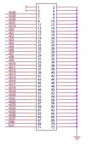
5 CompuScope 3200 connectors and headers CompuScope 3200 accepts digital data using a connector designed specially for ultra-fast digital signal transmission. A Trigger Out signal is also available on a BNC connector in order to synchronize CS3200 to the rest of the test system. The connectors and headers on the CS3200 card are shown below: Figure 1a: CS3200 connectors Figure 1b: Master/Slave connector* Figure 1: Connectors on CS3200 Digital input MDR connector is used to input up to 32 bits of single-ended or differential digital data lines, one clock input and one trigger input, all with 50 Ω characteristic impedance. This connector is designed to provide equivalent to coax performance by using copper conductors encapsulated in a specially formulated Teflon to provide the appropriate dielectric constant. This assembly is wrapped in a pleated copper foil, resulting in a 50 Ω transmission line impedance for each of the 68 conductors in the cable. For more information on the technology used in this connector, please visit Trigger Out BNC connector is used to output a 0 to 5 Volt, TTL signal which signifies that a trigger event has occurred on the CS3200. Master/Slave Pinout The Master/Slave connector on the top-left corner of the card is used to pass all the signals necessary to synchronize the Slave cards with the Master. CompuScope
6 Clock Output connector In some select cases, a user may want to drive the rest of the test system with the internal clock of the CS3200. A Clock Output Upgrade must be purchased in order to have access to this signal. A small, RF co-axial connector is available on the card, to which a 50 Ω cable can be attached to bring out a 5 Volt CMOS clock signal capable of driving a 50 Ω load. This upgrade is supplied with a cable that connects to the on-board RF connector on one end and a BNC connector mounted on a card bracket on the other. Note that an extra bracket is required to bring this signal outside the chassis. Note that in Master/Slave systems, the Clock Output signal is output from the Master card only. Figure 2: External Clock connector, single-card system or Master card 6 CompuScope 3200
7 CompuScope 3200 triggering Triggering allows the CompuScope 3200 to capture digital data just before or after an external event or a software command. CS3200 supports both pre- and post-trigger data capture. CompuScope 3200 allows the user to trigger the system on: External Trigger Software Trigger The user can also specify whether to trigger on the rising or falling edge of the External Trigger signal. Trigger Bus for Master/Slave systems In a Master/Slave system, a trigger signal on the Master card forces all Slave cards to trigger as well. A CompuScope 3200 Master/Slave system cannot trigger off of the External Trigger input of a Slave card. CompuScope
8 CompuScope 3200 digital input CompuScope 3200 is available with two different input configurations: Single-Ended, TTL/CMOS Inputs Differential, ECL/PECL Inputs Users must specify one or the other at the time of placing an order. The two configurations cannot be changed via software commands and require considerable changes to the input circuitry. As such, this change cannot be made in the field and must be done at the factory. Pin layout on CS3200 connector Single-ended, TTL/CMOS inputs CS3200 connector pin layout (Single-ended, TTL/CMOS inputs) 1 CLK 35 GND 2 D0 36 GND 3 D1 37 GND 4 D2 38 GND 5 D3 39 GND 6 D4 40 GND 7 D5 41 GND 8 D6 42 GND 9 D7 43 GND 10 D8 44 GND 11 D9 45 GND 12 D10 46 GND 13 D11 47 GND 14 D12 48 GND 15 D13 49 GND 16 D14 50 GND 17 D15 51 GND 18 D16 52 GND 19 D17 53 GND 20 D18 54 GND 21 D19 55 GND 22 D20 56 GND 23 D21 57 GND 24 D22 58 GND 25 D23 59 GND 26 D24 60 GND 27 D25 61 GND 28 D26 62 GND 29 D27 63 GND 30 D28 64 GND 31 D29 65 GND 32 D30 66 GND 33 D31 67 GND 34 TRIG IN 68 GND 8 CompuScope 3200
9 Pin layout on CS3200 connector Differential, ECL/PECL inputs CS3200 connector pin layout (Differential, ECL/PECL inputs) 1 CLK+ 35 CLK- 2 D0+ 36 D0-3 D1+ 37 D1-4 D2+ 38 D2-5 D3+ 39 D3-6 D4+ 40 D4-7 D5+ 41 D5-8 D6+ 42 D6-9 D7+ 43 D7-10 D8+ 44 D8-11 D9+ 45 D9-12 D D10-13 D D11-14 D D12-15 D D13-16 D D14-17 D D15-18 D D16-19 D D17-20 D D18-21 D D19-22 D D20-23 D D21-24 D D22-25 D D23-26 D D24-27 D D25-28 D D26-29 D D27-30 D D28-31 D D29-32 D D30-33 D D31-34 TRIG IN+ 68 TRIG IN- Input comparators The input stage for all inputs of the CS3200 is an EMI filter followed by a 50 Ω terminating resistor network wide bandwidth analog comparator. For single-ended input models, one of the inputs to the comparator is the input signal and the other is a programmable voltage level generated by an on-board DAC (Digital to Analog Converter). This enables the input stage to handle different voltage level CMOS signals, e.g. 3.3 Volt, 5 Volt etc. For differential input models, both inputs of the comparator are fed by the two differential signals corresponding to a particular input. For example, D0+ and D0- are fed into the inputs of the same comparator. CompuScope
10 Front-end FPGA At the heart of the CS3200 is a high-speed FPGA: all data lines, trigger and clock signals received from the outside world are injected into it; all data demultiplexing is done inside it; all acquisition control state machines exist in it; all sampling clock selection circuitry resides in it; all triggering is done within it; and all Master/Slave controls are handled inside it. This design allows for tremendous flexibility in adapting the CS3200 for a number of customized applications that require not only fast digital data acquisition, but also some data manipulation. Contact the factory with your custom requirement. This FPGA also allows the CS3200 to work in one of three input word widths of 32, 16 or 8 bits by demultiplexing (DMUX) the data. 10 CompuScope 3200
11 CompuScope 3200 compliance statement Category EC Declaration of Conformity EMC Standards or description Meets intent of Directive 89/336/EEC for Electromagnetic Compatibility. Compliance was demonstrated to the following specifications as listed in the Official Journal of the European Communities: EN EMC requirements for Class A electrical equipment for 1, 2, 3 measurement, control and laboratory use. IEC Electrostatic Discharge (Performance criterion B) IEC RF Electromagnetic Field (Performance criterion A) IEC Electrical Fast Transient/Burst Immunity (Performance criterion B) IEC Power Line Surge Immunity (Performance criterion B) IEC Conducted RF Immunity (Performance criterion A) IEC Voltage Dips and Interruptions Immunity (Performance criterion B) EN AC Power Line Harmonic Emissions Australia / New Zealand Declaration of Conformity - EMC Complies with EMC provision of Radio communications Act per the following standard(s): 1, 2, 3 AS/NZS /2 Industrial, Scientific and Medical Equipment: High-quality shielded cables must be used to ensure compliance to the above listed standards 2. Compliance demonstrated on a single card configuration 3. On the host PC used by the customer, all unused back panel slots must be covered with EMI blocking plates CompuScope
CompuScope bit, 100 MHz digital input card for the PCI bus. Features. We offer the widest range
 We offer the widest range of high-speed digitizers CompuScope 3200 32 bit, 100 MHz digital input card for the PCI bus and instrumentation cards available on the market today. Our powerful PC-based instrumentation
CompuScope bit, 100 MHz digital input card for the PCI bus
 CompuScope 3200 32 bit, 100 MHz digital input card for the PCI bus Fast and versatile digital capture card with logic analyzer characteristics for electronic test applications. FEATURES Capture 32 bits
CompuScope 3200C. 32 bit, 100 MHz digital input card for the CompactPCI/PXI bus. Features. We offer the widest range
 We offer the widest range of high-speed digitizers and instrumentation cards CompuScope 3200C 32 bit, 100 MHz digital input card for the CompactPCI/PXI bus available on the market today. Our powerful PC-based
Artisan Technology Group is your source for quality new and certified-used/pre-owned equipment
 Artisan Technology Group is your source for quality new and certified-used/pre-owned equipment FAST SHIPPING AND DELIVERY TENS OF THOUSANDS OF IN-STOCK ITEMS EQUIPMENT DEMOS HUNDREDS OF MANUFACTURERS SUPPORTED
CompuScope 1602 product introduction
 CompuScope 1602 product introduction CompuScope 1602 is 16 bit dual channel, 2.5 MS/s waveform digitizer card for the PCI Bus. Recognizing that until very recently, almost all multi-megahertz data acquisition
CompuScope product introduction
 CompuScope 12100 product introduction CompuScope 12100 is a 12 bit, waveform digitizer card for the PCI Bus, capable of 100 MS/s sampling on one channel and 50 MS/s sampling on two simultaneous channels.
CompuScope Ultra-fast waveform digitizer card for PCI bus. APPLICATIONS. We offer the widest range of
 We offer the widest range of high-speed and high-resolution digitizers available on the market CompuScope 1602 Ultra-fast waveform digitizer card for PCI bus today. Our powerful PC-based instrumentation
Artisan Technology Group is your source for quality new and certified-used/pre-owned equipment
 Artisan Technology Group is your source for quality new and certified-used/pre-owned equipment FAST SHIPPING AND DELIVERY TENS OF THOUSANDS OF IN-STOCK ITEMS EQUIPMENT DEMOS HUNDREDS OF MANUFACTURERS SUPPORTED
PCI-DIO. PCI Isolated Digital Input/Output Card. User Manual
 PCI-DIO PCI Isolated Digital Input/Output Card User Manual PCI-DIO User Manual Document Part N 0127-0192 Document Reference PCI-DIO\..\0127-0192.doc Document Issue Level 2.1 Manual covers PCBs identified
Product Information Sheet PDA14 2 Channel, 14-Bit Waveform Digitizer APPLICATIONS FEATURES OVERVIEW
 Product Information Sheet PDA 2 Channel, -Bit Waveform Digitizer FEATURES 2 Channels at up to 100 MHz Sample Rate Bits of Resolution Bandwidth from DC-50 MHz 512 Megabytes of On-Board Memory 500 MB/s Transfer
PCI Express XMC to PCI Express Adapter with J16 Connector Breakout DESCRIPTION
 PCI Express XMC to PCI Express Adapter with J16 Connector Breakout FEATURES Adapt one XMC.3 (PCI Express VITA 42.3) module to a PCI Express slot PCI Express x1 lane interface Active signal equalization
PCI-DDA08/16. Analog Output and Digital I/O. User's Guide
 PCI-DDA08/16 Analog Output and Digital I/O User's Guide Document Revision 3A March 2012 Copyright 2012 Trademark and Copyright Information Measurement Computing Corporation, InstaCal, Universal Library,
PMC to PCI Express Adapter with JN4 Connector Breakout
 Innovative Integration Real time solutions! Mar 2009, Rev 1.1 PMC to PCI Express Adapter with JN4 Connector Breakout FEATURES Adapt one PMC to a PCI Express slot 4 lane PCI Express Host Interface PCI 64
DAP 5200a Manual. Connector and Hardware Operation Reference. Version Microstar Laboratories, Inc.
 DAP 5200a Manual Connector and Hardware Operation Reference Version 1.02 Microstar Laboratories, Inc. The contents of this manual are protected by copyright. All rights are reserved. No part of this manual
PCI-PDISO8. Isolated Input and Relay Output. User's Guide
 PCI-PDISO8 Isolated Input and Relay Output User's Guide Document Revision 10A April 2012 Copyright 2012 Trademark and Copyright Information Measurement Computing Corporation, InstaCal, Universal Library,
14-Bit, 4-Channel, 50MSPS/Channel PMC Analog Input Board
 PMC66-14HSAI4 14-Bit, 4-Channel, 50MSPS/Channel PMC Analog Input Board With 66MHz PCI Compatibility, Multiple Ranges, and Data Packing Available also in PCI, cpci and PC104-Plus form factors as: PCI66-14HSAI4:
Product Information Sheet PX Channel, 14-Bit Waveform Digitizer
 Product Information Sheet PX14400 2 Channel, 14-Bit Waveform Digitizer FEATURES 2 Analog Channels at up to 400 MHz Sample Rate per Channel 14 Bits of Resolution Bandwidth from 100 KHz to 400 MHz 1 Gigabyte
DAP 4000a Manual. Installation Guide and Connector Reference. Version Microstar Laboratories, Inc.
 DAP 4000a Manual Installation Guide and Connector Reference Version 1.11 Microstar Laboratories, Inc. This manual contains proprietary information which is protected by copyright. All rights are reserved.
14HSAI4. 14-Bit, 4-Channel, 50MSPS/Channel PMC Analog Input Board. With 66MHz PCI Compatibility, Multiple Ranges, and Data Packing
 14HSAI4 14-Bit, 4-Channel, 50MSPS/Channel PMC Analog Input Board FEATURES: With 66MHz PCI Compatibility, Multiple Ranges, and Data Packing Available in PMC, PCI, cpci and PC104-Plus and PCI Express form
PCI-DIO24H Digital I/O User's Guide
 PCI-DIO24H Digital I/O User's Guide Document Revision 3A, May, 2009 Copyright 2009, Measurement Computing Corporation Trademark and Copyright Information Measurement Computing Corporation, InstaCal, Universal
PC104P--HPDI32A High-speed Parallel Digital I/O PMC Board 100 to 200 Mbytes/s Cable I/O with PCI-DMA engine
 PC104P--HPDI32A High-speed Parallel Digital I/O PMC Board 100 to 200 Mbytes/s Cable I/O with PCI-DMA engine Similar Product Features Include: 100 Mbytes per second (max) input transfer rate via the front
OPERATOR S MANUAL ATE 1/2 RACK POWER SUPPLY AUTOMATIC TEST EQUIPMENT MODEL
 OPERATOR S MANUAL ATE 1/2 RACK POWER SUPPLY AUTOMATIC TEST EQUIPMENT KEPCO INC. An ISO 9001 Company. MODEL 250W ATE 6-25, ATE 15-15, ATE 25-10, ATE 36-8, ATE 55-5, ATE 75-3, ATE 100-2.5, ATE 150-1.5, ATE
User s Guide. ivolt. I 2 C Bus/SMBus Voltage Level Translator. For 1.5 V to 5 V Applications.
 User s Guide ivolt I 2 C Bus/SMBus Voltage Level Translator For 1.5 V to 5 V Applications www.mcc-us.com Copyright 2004 by Micro Computer Control Corporation. All rights reserved. No part of this publication
Product Information Sheet PDA GHz Waveform Digitizer APPLICATIONS FEATURES OVERVIEW
 Product Information Sheet PDA1000 1 GHz Waveform Digitizer FEATURES Single channel at up to 1 GHz sample rate Bandwidth from DC-500 MHz 256 Megabytes of on-board memory 500 MB/s transfer via Signatec Auxiliary
PCM-DAC02. PCMCIA Dual Analog Outputs. User s Manual
 PCM-DAC02 PCMCIA Dual Analog Outputs User s Manual Revision 3 August, 2001 MEGA-FIFO, the CIO prefix to data acquisition board model numbers, the PCM prefix to data acquisition board model numbers, PCM-DAS08,
16-Channel 16-Bit Differential High-Speed PMC Analog Output Board
 66-16AO16 16-Channel 16-Bit Differential High-Speed PMC Analog Output Board With 450,000 Samples per Second per Channel, and 66 MHz PCI Support Available in PMC, PCI, cpci and PC104-Plus and PCI Express
PC-CARD-D24/CTR3 Digital I/O and Counter Board User s Guide
 PC-CARD-D24/CTR3 Digital I/O and Counter Board User s Guide Document Revision 6, April, 2007 Copyright 2007, Measurement Computing Corporation Your new Measurement Computing product comes with a fantastic
Digital Camera Image Acquisition
 NI PCI-1424, NI PCI-1422 NI PCI-1424 RS422, LVDS, or TTL area- and line-scan camera compatibility Full 8-, 10-, 12-, 14-, 16-, 24-, and 32-bit resolution (grayscale or color) 50 MHz pixel clock rate with
P344 4-lane MIPI DPhy Stimulus Generator Data Sheet & User Manual. January Rev 1.31
 P344 4-lane MIPI DPhy Stimulus Generator Data Sheet & User Manual January 2018 - Rev 1.31 P344 MIPI D-PHY Probe IMPORTANT SAFETY and USEAGE INFORMATION Please review the following safety precautions to
USB-1024LS. 24-bit Digital I/O Low-speed USB 2.0 device. User s Guide
 USB-1024LS 24-bit Digital I/O Low-speed USB 2.0 device User s Guide USB-1024LS USB-based Digital I/O Module User's Guide Document Revision 2A, May, 2006 Copyright 2006, Measurement Computing Corporation
User s Guide. IP-201 I 2 C Bus Multiplexer Board Revision 2.
 User s Guide IP-201 I 2 C Bus Multiplexer Board Revision 2 www.mcc-us.com Introduction The MCC IP-201 is a four channel I²C Bus Multiplexer Board that provides an easy way to connect multiple I²C Buses
16-Bit, 12-Channel, 2-MSPS PMC Analog Input/Output Board
 66-16AISS8AO4 16-Bit, 12-Channel, 2-MSPS PMC Analog Input/Output Board With Eight Simultaneously Sampled Analog Inputs, Four Analog Outputs, and Input Sampling Rates to 2.0 MSPS per channel Available in
Coda cx1 EMI/EMC Test Procedure
 Coda cx1 EMI/EMC Test Procedure CDL 1-TP07-0400:0209 MIT Ref. 85-01050.03 Revision 1.0 28 th March 2002 CDL 1-TP07-0400:0209 Contents 1 Introduction... 1 1.1 Activity Description... 1 2 Requirements...
User's Manual. PXI Power Distribution Module
 User's Manual PXI Power Distribution Module Version 2.5, June 2010 XIA LLC 31057 Genstar Road Hayward, CA 94544 USA Phone: (510) 401-5760; Fax: (510) 401-5761 http://www.xia.com Disclaimer Information
AccuStar Electronic Clinometer
 AccuStar Electronic Clinometer Single Axis ± 60 Range The AccuStar Electronic Clinometer is an extremely accurate angle measurement device. This compact and rugged sensor is ideal where space is critical
Includes P1/P2/P3/P4 compatibility for Analog I/O, Digital I/O, & Pulse/Frequency
 DBK214 16-Connector BNC Interface Module Includes P1/P2/P3/P4 compatibility for Analog I/O, Digital I/O, & Pulse/Frequency Overview 1 Block Diagram 2 Connection Tips 3 System Examples 4 Using the Screw-Terminal
RT4F-48V/50A-WAC RECTIFIER
 The RT4F-48V/50A-WAC is a switched mode rectifier (SMR) module designed to provide up to 58A of output current into a 48V nominal system, over a wide range of AC input voltage. This rectifier has been
PXDAC4800. Product Information Sheet. 1.2 GSPS 4-Channel Arbitrary Waveform Generator FEATURES APPLICATIONS OVERVIEW
 Product Information Sheet PXDAC4800 1.2 GSPS 4-Channel Arbitrary Waveform Generator FEATURES 4 AC-Coupled or DC-Coupled DAC Channel Outputs 14-bit Resolution @ 1.2 GSPS for 2 Channels or 600 MSPS for 4
SCIENCEWORKSHOP 750 INTERFACE. Instruction Sheet for the PASCO Model CI Introduction
 Instruction Sheet for the PASCO Model CI-7500 012-06772A 4/98 $1.00 SCIENCEWORKSHOP 750 INTERFACE ventilation louvres POWER power light ScienceWorkshop 750 1 2 3 4 A B C DIGITAL CHANNELS ANALOG CHANNELS
DaqBoard/1000. Series 16-Bit, 200-kHz PCI Data Acquisition Boards
 16-Bit, 200-kHz PCI Data Acquisition Boards Features 16-bit, 200-kHz A/D converter 8 differential or 16 single-ended analog inputs (software selectable per channel) Up to four boards can be installed into
PMC-HPDI32A-ASYNC High-speed Serial I/O PCI Board
 PMC-HPDI32A-ASYNC High-speed Serial I/O PCI Board Features Include: Data rate of 5.0 megabits per second 8 Bits transmitter. LSB First. Software Selectable Even / Odd Parity. Software Selectable No Parity
PC104P-24DSI Channel 24-Bit Delta-Sigma PC104-Plus Analog Input Board
 PC104P-24DSI12 12-Channel 24-Bit Delta-Sigma PC104-Plus Analog Input Board With 200 KSPS Sample Rate per Channel and Optional Low-Power Configuration Available also in PCI, cpci and PMC form factors as:
Test and Measurements Automated Systems Component Device Testing Semiconductor Processing & Burn-in Aerospace & Satellite Testing
 The TSR10 is a 10 kw, 3-phase input voltage 360-440 VAC power supply with an adjustable DC output voltage between 0.5 V and 50 V and output current between 0.5 A and 200 A. The power supply has been designed
USB-201. Analog and Digital I/O. User's Guide. January Rev 7 Measurement Computing Corporation
 USB-201 Analog and Digital I/O User's Guide January 2019. Rev 7 Measurement Computing Corporation Trademark and Copyright Information Measurement Computing Corporation, InstaCal, Universal Library, and
PC-CARD-DAC08. User s Manual
 PC-CARD-DAC8 Analog Outputs & Digital I/O User s Manual Revision March, 2 (C) Copyright 2, Measurement Computing Corporation MEGA-FIFO, the CIO prefix to data acquisition board model numbers, the PCM prefix
Differential Probe. GDP-040D for GDS-200 & GDS-300 Series QUICK START GUIDE GW INSTEK PART NO. 82DP-040D0MA1 ISO-9001 CERTIFIED MANUFACTURER
 Differential Probe GDP-040D for GDS-200 & GDS-300 Series QUICK START GUIDE GW INSTEK PART NO. 82DP-040D0MA1 ISO-9001 CERTIFIED MANUFACTURER This manual contains proprietary information, which is protected
ATS860. ATS MS/s 8-Bit PCI Digitizer
 2 channels sampled at 8-Bit resolution 250 MS/s simultaneous real-time sampling rate on each input ±20 mv to ±10 V input range Up to 256 Million samples of on-board acquisition memory per channel Optional
PC104-CTR10HD. User s Manual
 PC104-CTR10HD User s Manual Revision 2 October, 2000 MEGA-FIFO, the CIO prefix to data acquisition board model numbers, the PCM prefix to data acquisition board model numbers, PCM-DAS08, PCM-D24C3, PCM-DAC02,
z482 Digital I/O Module PXI Express
 TECHNICAL SPECIFICATIONS z482 Digital I/O Module PXI Express 2017 LitePoint, A Teradyne Company. All rights reserved. Port Description OUTPUT (VHDCI, 68-Position, Receptacle) z482 Digital I/O Module PXI
Low-Cost Multifunction DAQ for USB
 NI USB-6008, NI USB-6009 Small and portable 12 or 14-bit input resolution, at up to 48 ks/s Built-in, removable connectors for easier and more cost-effective connectivity 2 true DAC analog outputs for
M ICROSTAR LA BORATORIE S TM
 M ICROSTAR LA BORATORIE S TM 2265 116th Avenue N.E., Bellevue, WA 98004 Sales & Customer Support: (425) 453-2345 Finance & Administration: (425) 453-9489 Fax: (425) 453-3199 World Wide Web: http://www.mstarlabs.com/
TXM1.8U TXM1.8U-ML. Universal modules TX-I/O
 8 173 TX-I/O niversal modules TXM1.8 TXM1.8-ML Two fully compatible versions: TXM1.8: 8 inputs/outputs with LED signal / fault indication TXM1.8-ML: As TXM1.8, but with additional local override facility
PCIe-16AO64C. 16-Bit, 64/32-Channel, 500KSPS PCI Express Analog Output Board. With Optional Outputs-Disconnect
 PCIe-16AO64C 16-Bit, 64/32-Channel, 500KSPS PCI Express Analog Output Board With Optional Outputs-Disconnect Features Include: Precision 16-Bit simultaneously-clocked analog outputs: R-2R DAC per channel
H-series (Rectifier Module)
") H-series (Rectifier Module) Overview: The rectifier modules provide unprecedented power density and power levels in a true plug and play format. With a wide range of available voltages, power ratings,
H-series (Rectifier Module) Overview: The rectifier modules provide unprecedented power density and power levels in a true plug and play format. With a wide range of available voltages, power ratings,
PCIe-24DSI12WRCIEPE 24-Bit, 12-Channel, 105KSPS Transducer Input Module With 12 Wide-Range Delta-Sigma Input Channels and IEPE Current Excitation
 PCIe-24DSI12WRCIEPE 24-Bit, 12-Channel, 105KSPS Transducer Input Module With 12 Wide-Range Delta-Sigma Input Channels and IEPE Current Excitation Features Include: 12 wide-range 24-Bit unbalanced differential
PCIe-20AO8C500K. 20-Bit 8-Output 500KSPS Precision Wideband. PCI Express Short-Card Analog Output Module
 PCIe-20AO8C500K 20-Bit 8-Output 500KSPS Precision Wideband PCI Express Short-Card Analog Output Module Features Include: Eight Single-ended or 3-Wire Differential 20-Bit analog output channels. Simultaneous
NI PXI-2567 Specifications
 NI PXI-2567 Specifications 64-Channel Relay Driver Module This document lists specifications for the NI PXI-2567 relay driver module. All specifications are subject to change without notice. Visit ni.com/manuals
PC104P66-16HSDI4AO4:
 PMC66-16HSDI4AO4 16-Bit, 8-Channel, 1-MSPS PMC Analog Input/Output Board With Four Simultaneously Sampled Sigma-Delta Analog Inputs, and Four Buffered Analog Outputs, Available also in PCI, cpci and PC104-Plus
Contents INTRODUCTION...1 CARD SETUP...2 INSTALLATION TECHNICAL DESCRIPTION SPECIFICATIONS... 14
 Contents INTRODUCTION...1 OVERVIEW...1 WHAT S INCLUDED...1 FACTORY DEFAULT SETTINGS...1 CARD SETUP...2 ADDRESS SELECTION...2 IRQ SELECTION...3 INTERRUPT MODES...4 RS-485 ENABLE MODES...5 CONNECTOR PIN
Features: Analog to Digital: 12 bit resolution TTL outputs, RS-232 tolerant inputs 4.096V reference (1mV/count) 115K max speed
 115K max speed") The Multi-I/O expansion board gives users the ability to add analog inputs and outputs, UART capability (for GPS or modem) and isolated high current outputs to the Flashlite 386Ex. Available in several
The Multi-I/O expansion board gives users the ability to add analog inputs and outputs, UART capability (for GPS or modem) and isolated high current outputs to the Flashlite 386Ex. Available in several
3-Card Slot, Includes P1/P2/P3/P4 compatibility for Analog I/O, Digital I/O, & Pulse/Frequency
 DBK213 Screw-Terminal & Expansion Card Module 3-Card Slot, Includes P1/P2/P3/P4 compatibility for Analog I/O, Digital I/O, & Pulse/Frequency Overview 1 Connection Tips 2 Installing DBK Cards 3 System Examples
CMX18 FEATURES A 18-SLOT 3U PXI EXPRESS CHASSIS
 83-0062-000 15A D A T A S H E E T CMX18 18-SLOT 3U PXI EXPRESS CHASSIS FEATURES 18-slot PXI Express chassis with 1 system controller slot, 6 peripheral slots, 10 hybrid slots, and 1 timing slot High bandwidth
cpci6u64-20aof16c500kr
 cpci6u64-20aof16c500kr 20-Bit 16-Output 500KSPS Precision Wideband cpci 6U Analog Output Board With 8th-Order reconstruction output filters Features Include: 16 Single-ended or optional 3-Wire Differential
PC104P66-18AISS6C: 18-Bit, 6-Channel, 550KSPS Analog Input Module. With Six Simultaneously Sampled Analog Inputs and 8-Bit Digital I/O Port
 66-18AISS6C 18-Bit, 6-Channel, 550KSPS Analog Input Module With Six Simultaneously Sampled Analog Inputs and 8-Bit Digital I/O Port Available in PMC, PCI, cpci and PC104-Plus and PCI Express form factors
CIO-DO48H, CIO-DO96H and CIO-DO192H. User s Guide
 CIO-DO48H, CIO-DO96H and CIO-DO192H User s Guide Revision 4A April, 2001 Trademark and Copyright Information Measurement Computing Corporation, InstaCal, Universal Library, and the Measurement Computing
24DSI16WRC Wide-Range 24-Bit, 16-Channel, 105KSPS Analog Input Module With 16 Wide-Range (High-Level, Low-Level) Delta-Sigma Input Channels
 Delta-Sigma Input Channels") 24DSI16WRC Wide-Range 24-Bit, 16-Channel, 105KSPS Analog Input Module With 16 Wide-Range (High-Level, Low-Level) Delta-Sigma Input Channels Features Include: Available in PMC, PCI, cpci and PC104-Plus
24DSI16WRC Wide-Range 24-Bit, 16-Channel, 105KSPS Analog Input Module With 16 Wide-Range (High-Level, Low-Level) Delta-Sigma Input Channels Features Include: Available in PMC, PCI, cpci and PC104-Plus
Analog Input Sample Rate
 ECONseries Low Cost USB Data Acquisition Modules Overview The ECONseries is a flexible yet economical series of multifunction DAQ modules. You chse the number of analog I/O and digital I/O channels, the
PCI Hardware and Driver Installation Guide
 GAGE APPLIED TECHNOLOGIES PCI Hardware and Driver Installation Guide Reorder #: MKT-HWM-PCI01-Install 0408 Copyright Gage Applied Technologies 2004 First Edition (August 2004) GAGE, COMPUSCOPE, and GAGESCOPE
HMISBC Rear Module controller panel - Dig 8 inputs/8 outputs +Ana 4 In/2 Out
 Characteristics Rear Module controller panel - Dig 8 inputs/8 outputs +Ana 4 In/2 Out Main Range of product Product or component type Complementary Supply [Us] rated supply voltage Immunity to microbreaks
PCIe-16AOF Bit, 64/32-Channel, 500KSPS PCI Express Analog Output Board. With Reconstruction Output Filters
 PCIe-16AOF64 16-Bit, 64/32-Channel, 500KSPS PCI Express Analog Output Board With Reconstruction Output Filters Features Include: Precision 16-Bit simultaneously-clocked analog outputs: R-2R DAC per channel
CLK1, CLKIN, CLKOUT, OUTA, OUTB
 9-82; Rev 2; 5/ Evaluation Kit General Description The evaluation kit (EV kit) is a fully assembled and tested circuit board that contains all the components necessary for evaluating the. The is a dual,0-bit,
Chapter 1 Introducing the OM-USB-1608FS-Plus... 6 Functional block diagram... 6
 Table of Contents Preface About this User's Guide... 5 What you will learn from this user's guide... 5 Conventions in this user's guide... 5 Where to find more information... 5 Chapter 1 Introducing the
Product Information Sheet PX14400D 2 Channel, DC-Coupled, 14-Bit Digitizer
 Product Information Sheet PX14400D 2 Channel, DC-Coupled, 14-Bit Digitizer Fsab FEATURES 2 Analog Channels at up to 400 MHz Sample Rate per Channel 14 Bits of Resolution Bandwidth from DC to 200 MHz 200
ATS GS/s 8-Bit PCI Express Digitizer
 1.6 GB/s PCI Express (8-lane) interface 2 channels sampled at 8-bit resolution 1 GS/s simultaneous real-time sampling rate on each input Up to 4 GigaByte dual-port memory Continuous streaming mode ±200mV
16AIO 16-Bit Analog Input/Output Board With 32 Input Channels, 4 Output Channels and 16-Bit Digital I/O Port
 16AIO 16-Bit Analog Input/Output Board With 32 Input Channels, 4 Output Channels and 16-Bit Digital I/O Port Features Include: Available in PMC, PCI, cpci and PC104-Plus and PCI Express form factors as:
Installation Instructions
 Installation Instructions This document provides information on: important pre-installation considerations power supply requirements initial handling installing the module using the indicators for troubleshooting
8 AI (12-Bit, 10 ks/s), 2 AO (150 Hz), 12 DIO USB Multifunction I/O Device
, 2 AO (150 Hz), 12 DIO USB Multifunction I/O Device") SPECIFICATIONS USB-6008 8 AI (12-Bit, 10 ks/s), 2 AO (150 Hz), 12 DIO USB Multifunction I/O Device Definitions Warranted specifications describe the performance of a model under stated operating conditions
SPECIFICATIONS USB-6008 8 AI (12-Bit, 10 ks/s), 2 AO (150 Hz), 12 DIO USB Multifunction I/O Device Definitions Warranted specifications describe the performance of a model under stated operating conditions
PCI-DAS1002 Multifunction Analog & Digital I/O User's Guide
 PCI-DAS1002 Multifunction Analog & Digital I/O User's Guide Document Revision 5A, March, 2009 Copyright 2009, Measurement Computing Corporation Trademark and Copyright Information Measurement Computing
TM3AI4 module TM3-4 analog inputs
 Characteristics module TM3-4 analog inputs Main Range of product Product or component type Range compatibility Analogue input number 4 Analogue input type Complementary Analogue input resolution Permissible
XMC-16AI32SSC1M. 32-Channel, Differential, 16-Bit Simultaneous Sampling XMC Analog Input Board
 32-Channel, Differential, 16-Bit Simultaneous Sampling XMC Analog Input Board With 1.0MSPS Sample Rate per Channel, Time-tagging and Low-latency access 32 Differential analog inputs with dedicated 1.0MSPS
RoHS Compliant PCI Isolated Digital Input/Output Card User Guide
 PCI - DIO RoHS Compliant PCI Isolated Digital Input/Output Card User Guide Document Reference Product User Guide Document Issue Level 1.2 Table of Contents Table of Contents Introduction...3 Copyright...3
Safety Standards. Model Number: Unit Weight:
 MEA-250A24C Highlights & Features Meet Efficiency Level VI Safety Approvals to IEC 60601-1 3.1 Ed. & IEC 60950-1 Compliant with IEC 60601-1-2 3 th and 4 th Ed. Requirements IP22 ingress protection rating
PDD-300 pulsed diode driver
 rev 1.08 / 2019 02 13 PDD-300 pulsed diode driver User manual Warning! This equipment may be dangerous. Please read user manual before starting operations. Important note. Please measure output with adequate
12-Channel, 12-Bit PMC Analog Input/Output Board
 12-Channel, 12-Bit PMC Analog Input/Output Board With Eight Simultaneously-Sampled Wide-Range Inputs at 2.0 MSPS per Channel, Four Analog Outputs, and 16-Bit Digital I/O Port Available also in PCI, cpci
16-Bit, 12-Channel, 2-MSPS PMC Analog Input/Output Board
 PMC66-16AISS8AO4 16-Bit, 12-Channel, 2-MSPS PMC Analog Input/Output Board With Eight Simultaneously Sampled Analog Inputs, Four Analog Outputs, and Input Sampling Rates to 2.0 MSPS per channel Available
USB-201-OEM. Analog and Digital I/O. User's Guide
 USB-201-OEM Analog and Digital I/O User's Guide Document Revision 7A December 2014 Copyright 2014 Trademark and Copyright Information Measurement Computing Corporation, InstaCal, Universal Library, and
Installation Instructions
 Installation Instructions This document provides information on: important pre-installation considerations power supply requirements initial handling installing the module using the indicators for troubleshooting
SR3_Analog_32. User s Manual
 SR3_Analog_32 User s Manual by with the collaboration of March 2nd 2012 1040, avenue Belvédère, suite 215 Québec (Québec) G1S 3G3 Canada Tél.: (418) 686-0993 Fax: (418) 686-2043 1 INTRODUCTION 4 2 TECHNICAL
These power supplies are ideal for telecom, datacom, industrial equipment and other applications.
 The ABC60 Series of AC-DC open-frame power supplies, with its wide universal 90-264 VAC input range and high power density, is available at 60 W of output power and a variety of single and multiple output
ICF-1150 Series Quick Installation Guide
 ICF-1150 Series Quick Installation Guide Second Edition, March 2012 2012 Moxa Inc. All rights reserved. P/N: 1802011500011 Overview Introduction The ICF-1150 series fiber converters are equipped with a
PCI-DAS08 Analog input and Digital I/O User's Guide
 PCI-DAS08 Analog input and Digital I/O User's Guide Document Revision 5A, June, 2006 Copyright 2006, Measurement Computing Corporation Trademark and Copyright Information Measurement Computing Corporation,
A variety of ECONseries modules provide economical yet flexible solutions
 Economy USB Mini-Instruments Flexible Yet Economical A variety of low-cost modules are available to provide flexible yet economical solutions. Choose the number of analog I/O and digital I/O channels,
Best practices for EMI filtering and IC bypass/decoupling applications
 X2Y Component Connection and PCB Layout Guidelines Best practices for EMI filtering and IC bypass/decoupling applications X2Y Attenuators, LLC 1 Common X2Y Circuit Uses EMI FILTERING Conducted and Radiated
EFE300 / EFE400 EFE300M / EFE400M
 EFE300 / EFE400 EFE300M / EFE400M AC/DC Power Supply Series APPLICATION NOTE 68892 EFE300_400 App note 8.doc Document Number 68892 Page 1 of 13 1. INPUT... 3 AC INPUT LINE REQUIREMENTS... 3 2. DC OUTPUT...
CompuGen ISA Hardware Manual and Driver Installation Guide
 GAGE APPLIED TECHNOLOGIES CompuGen ISA Hardware Manual and Driver Installation Guide Reorder #: MKT-HWM-ISA01 0506 Copyright Gage Applied Technologies 1999, 2000, 2004, 2005 First Edition (June 2005) GAGE,
TM3TI8T module TM3-8 inputs temperature
 Characteristics module TM3-8 inputs temperature Main Range of product Product or component type Range compatibility Analogue input number 8 Analogue input type Complementary Analogue input resolution Input
Electrical Specifications. Input Current 115 VAC: 1 A max. 230 VAC: 0.5 A max.
 MLP75 Medical Features 3 x 2 x 1 Inches Form factor 75 Watts Convection Approval to EN60601 3 rd Edition Efficiencies upto 93% -40 to 70 degree operating temperature Dual fusing Thermal Shut-Down feature
A variety of ECONseries modules provide economical yet flexible solutions. Waveform Generation
 ECONseries BUS: USB Type: Economy, Mini-Instruments ECONseries Economy USB Mini-Instruments Flexible Yet Economical A variety of low-cost ECONseries modules are available to provide flexible yet economical
CPCI-HPDI32ALT High-speed 64 Bit Parallel Digital I/O PCI Board 100 to 400 Mbytes/s Cable I/O with PCI-DMA engine
 CPCI-HPDI32ALT High-speed 64 Bit Parallel Digital I/O PCI Board 100 to 400 Mbytes/s Cable I/O with PCI-DMA engine Features Include: 200 Mbytes per second (max) input transfer rate via the front panel connector
16-Channel 16-Bit PMC Analog I/O Board
 16-Channel 16-Bit PMC Analog I/O Board With 8 Input Channels, 8 Output Channels, and Autocalibration Eight 16-Bit Analog Output Channels with 16-Bit D/A Converter per Channel Eight 16-Bit Analog Input