Adafruit MAX31865 RTD PT100 or PT1000 Amplifier
|
|
|
- Bruce Riley
- 5 years ago
- Views:
Transcription

1 Adafruit MAX31865 RTD PT100 or PT1000 Amplifier Created by lady ada Last updated on :08:40 AM UTC
2 Guide Contents Guide Contents Overview Pinouts Power Pins: SPI Logic pins: Sensor Terminal Blocks Configuration Jumpers Assembly Prepare the header strip: Solder! RTD Wiring & Config 4-Wire RTDs 3-Wire RTDs 2-Wire RTDs How To Wire Up! 4-Wire Sensors 3-Wire Sensors 2 Wire Sensor Wiring & Test SPI Wiring Download Adafruit_MAX31865 library Attach PT100 or PT1000 RTD Load Demo More Accuracy Library Reference Reading Resistance Calculating Temperature Faults Downloads Files Schematic & Fabrication Print Adafruit Industries Page 2 of 26
 are temperature sensors that contain a resistor that changes resistance value as its temperature changes, basically a kind of thermistor.")
3 Overview For precision temperature sensing, nothing beats a Platinum RTD. Resistance temperature detectors (RTDs) are temperature sensors that contain a resistor that changes resistance value as its temperature changes, basically a kind of thermistor. In this sensor, the resistor is actually a small strip of Platinum with a resistance of 100 or 1000 ohms at 0 C, thus the name PT100/PT1000. Compared to most NTC/PTC thermistors, the PT type of RTD is much most stable and precise (but also more expensive) PT's have been used for many years to measure temperature in laboratory and industrial processes, and have developed a reputation for accuracy (better than thermocouples), repeatability, and stability. Adafruit Industries Page 3 of 26


4 However, to get that precision and accuracy out of your PT100x RTD you must use an amplifier that is designed to read the low resistance. Better yet, have an amplifier that can automatically adjust and compensate for the resistance of the connecting wires. If you're looking for a great RTD sensor, today is your lucky day because we have a lovely Adafruit RTD Sensor Amplifier with the MAX31865 sensor. Adafruit Industries Page 4 of 26

5 We've carried various MAXIM thermocouple amplifiers and they're great - but thermocouples don't have the best accuracy or precision, for when the readings must be as good as can be. The MAX31865 handles all of your RTD needs, and can even compensate 3 or 4 wire RTDs for better accuracy. Connect to it with any microcontroller over SPI and read out the resistance ratio from the internal ADC. We put a 0.1% resistor as a reference resistor on the breakout. We have some example code that will calcuate the temperature based on the resistance for you. The PT100 version of the breakout uses 430Ω The PT1000 version uses 4300Ω We even made the breakout 5V compliant, with a 3.3V regulator and level shifting, so you can use it with any Arduino or microcontroller Each order comes with one assembled RTD amplifier breakout board. Also comes with two 2-pin terminal blocks (for connecting to the RTD sensor) and pin header (to plug into any breadboard or perfboard). A required PT100 or PT1000 RTD is not included! (But we stock them in the shop). Some soldering is required to solder the headers and terminal blocks to the breakout, but it's an easy task with soldering tools. Adafruit Industries Page 5 of 26

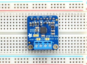
6 Pinouts The MAX31865 is a tiny surface mount chip, and it needs a lot of other parts to make it work, so we've got it on a nice breakout board for you. You can control the chip and read data from it using the breakouts at the bottom. Let's go thru these! Power Pins: Vin - this is the power pin. Since the chip uses 3 VDC, we have included a voltage regulator on board that will take 3-5VDC and safely convert it down. To power the board, give it the same power as the logic level of your microcontroller - e.g. for a 5V micro like Arduino, use 5V 3Vo - this is the 3.3V output from the voltage regulator, you can grab up to 100mA from this if you like GND - common ground for power and logic SPI Logic pins: All pins going into the breakout have level shifting circuitry to make them 3-5V logic level safe. Use whatever logic level is on Vin! SCK - This is the SPI Clock pin, its an input to the chip SDO - this is the Serial Data Out / Master In Slave Out pin, for data sent from the MAX31865 to your processor SDI - this is the Serial Data In / Master Out Slave In pin, for data sent from your processor to the MAX31865 CS - this is the Chip Select pin, drop it low to start an SPI transaction. Its an input to the chip If you want to connect multiple MAX31865's to one microcontroller, have them share the SDI, SDO and SCK pins. Then assign each one a unique CS pin. RDY (Ready) - is a data-ready indicator pin, you can use this pin to speed up your reads if you are writing your own driver. Our Arduino driver doesn't use it to save a pin Adafruit Industries Page 6 of 26

7 Sensor Terminal Blocks If you have an RTD sensor, you need to connect it somehow! the terminal block area is where you can clamp down to the sensor wires. There are four contacts, but you can use 2, 3 or 4 wire sensors. You may need to solder or jumper some pads deending on how many wires you want to use. You can also use a 3 or 4 wire sensor as a 3-wire or 2-wire sensor (just dont connect the extra wires). Check the RTD wiring page for details on how to connect the sensor you've got! Configuration Jumpers Adafruit Industries Page 7 of 26

8 By default the sensor is wired up for 4-wire RTD usage but can be set up for 2 or 3 wire very easily. For 4-wire usage, do nothing with the jumpers! For 3-wire usage. Solder closed the jumper labeled 2/3 Wire and cut the wire connecting the left side of the 2-way jumper right above Rref. Then solder closed the right side labeled 3 For 2-wire usage, solder closed the two triangular jumpers below the terminal blocks (or put short wire jumpers between the two terminal blocks on either side (essentially jumpering the two right side terminal holes together, and same for left side) Check the RTD wiring page for details on how to connect the sensor you've got! Adafruit Industries Page 8 of 26
9 Assembly Adafruit Industries Page 9 of 26
). Adafruit Industries https://learn.")
10 Prepare the header strip: Cut the strip to length if necessary. It will be easier to solder if you insert it into a breadboard - long pins down Solder! Be sure to solder all pins for reliable electrical contact. (For tips on soldering, be sure to check out our Guide to Excellent Soldering ( Adafruit Industries Page 10 of 26


11 Adafruit Industries Page 11 of 26


12 Next we will solder in the two 3.5mm terminal blocks used to connect power & the motor to the breakout board. Make sure the open parts of the terminals face outwards so you can easily connect wires To make it easier to keep these in place, you can use some tape to hold down the two header pieces. Tacky clay also works, whatever you've got handy! Adafruit Industries Page 12 of 26


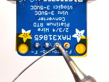
13 Solder in both pins of each terminal block. You can remove the tape when done. Adafruit Industries Page 13 of 26


14 OK You're done! Adafruit Industries Page 14 of 26

15 RTD Wiring & Config RTDs are really very simple devices: just a small strip of Platinum that measures 100Ω or 1000Ω exactly at 0 C. Bonded to the PT100/PT1000 are 2, 3 or 4 wires. 4-Wire RTDs We'll explain the 4-wire version since that's the most complex. Normally if you want to measure a resistor you just connect your multimeter to each side of the resistor. The multimeter puts a small current through the resistor and measures the voltage generated across it (remember V = I * R). This works great for just about all resistors. However, for very precise readings of low-resistance resistors, you also have to account for the wires connected! For basic resistors, they are only good to 5% anyways so we don't mind the resistance of the wires. For RTDs, the wires, especially the 1 meter long ones, are 1, 2 maybe even 4Ω of extra resistance! That can add up to half or even a full C! No good, we want to make sure that resistance is not included in our measurement Thus, the 4-wire RTD. Each side of the RTD has two wires attached. Each wire is maybe 1Ω of resistance. When connected to the amplifier, the smart amp will measure the voltage across the RTD and also across the wire pairs. For example, here's the approximate resistances of a 4-Wire PT100 RTD at 0 C (for a PT1000, the middle resistance would be (1002Ω rather than 102Ω) (Remember that the middle resistance or 1002 Ω - will vary with temperature, but the 2Ω wires will not) When the amp measures this sensor, it will measure the resistance between one set of red and blue wires. It will then measure the resistances between the red wires and blue wires. Then divide those resistances by half - since there's two wires and we just want the resistance of one wire. The final result is = 100Ω 3-Wire RTDs Adafruit Industries Page 15 of 26

16 These are very similar to the 4-wire type but there is only one 'pair' of connected wires. The reasoning for this is that the wires for the RTD are all pretty much the same gauge and length, so rather than having two pairs, the amplifier will just read one pair and use that resistance as the same for both wires. 2-Wire RTDs These are as simple as it gets, only one wire per side. You may need to calibrate the sensor by putting it an ice batch to get the resistance at 0 C (say 102Ω) and then subtracting 100Ω to figure out the collective resistance of the connection wires! Adafruit Industries Page 16 of 26
 and which connect through the RTD. Chances are the wires that connect together are the same color.")
17 How To Wire Up! 4-Wire Sensors Connect the four wires to each of the pads. Use a multimeter to determine which wires connect together directly (2 ohms or so between them) and which connect through the RTD. Chances are the wires that connect together are the same color. The two pairs connect so that the ones that are connected together go into the two matching terminal blocks on left or right. It doesn't matter which of the matched pair is on the outside or inside. It doesn't matter which of the match pairs are on the left or right. Do not solder closed any jumpers or cut any jumpers. Use as is! Adafruit Industries Page 17 of 26
18 3-Wire Sensors Connect the three wires to the three right-most contacts. Use a multimeter to determine which wires connect together directly (2 ohms or so between them) and which connect through the RTD. Chances are the wires that connect together are the same color. The two wires that are connected together should go in the right-most blocks (labeled F+ and RTD+). It doesn't matter which of the matched pair is on the outside or inside. The third wire that is on the other side of the RTD connects to the left (marked F- or RTD-). It doesn't matter which slot it's in! Adafruit Industries Page 18 of 26

19 You will have to cut the thin trace in between the 2-way jumper on the right side of the board, and then solder closed the blob on the right side. Then next to the terminal block on the left, solder closed that jumper as well. Alternatively you can put a piece of wire into the terminal blocks to 'short' them 2 Wire Sensor This is the easiest wiring, you can just use either terminal block slot on the sides for each wire. Then either solder closed the jumpers next to the RTD terminal block or put little wires in the right and left terminal blocks to short them together. Adafruit Industries Page 19 of 26

20 Wiring & Test You can easily wire this breakout to any microcontroller, we'll be using an Arduino. For another kind of microcontroller, as long as you have 4 available pins it is possible to 'bit-bang SPI' or you can use hardware SPI if you like. Just check out the library, then port the code. SPI Wiring Since this is a SPI-capable sensor, we can use hardware or 'software' SPI. To make wiring identical on all Arduinos, we'll begin with 'software' SPI. The following pins should be used: Connect Vin to the power supply, 3V or 5V is fine. Use the same voltage that the microcontroller logic is based off of. For most Arduinos, that is 5V Connect GND to common power/data ground Connect the SCK pin to Digital #13 but any pin can be used later Connect the SDO pin to Digital #12 but any pin can be used later Connect the SDI pin to Digital #11 but any pin can be used later Connect the CS pin Digital #10 but any pin can be used later Later on, once we get it working, we can adjust the library to use hardware SPI if you desire, or change the pins to other Download Adafruit_MAX31865 library To begin reading sensor data, you will need to download Adafruit_MAX31865 from our github repository. You can do that by visiting the github repo and manually downloading or, easier, just click this button to download the zip Download latest Adafruit MAX31865 Arduino Adafruit Industries Page 20 of 26

21 Library Rename the uncompressed folder Adafruit_MAX31865 and check that the Adafruit_MAX31865 folder contains Adafruit_MAX31865.cpp and Adafruit_MAX31865.h Place the Adafruit_MAX31865 library folder your arduinosketchfolder/libraries/ folder. You may need to create the libraries subfolder if its your first library. Restart the IDE. We also have a great tutorial on Arduino library installation at: Restart the IDE Attach PT100 or PT1000 RTD You'll need to attach an RTD, for this demo we'll be using a 3-wire 1 meter long one but you can adjust the demo if you have a 2 or 4 wire. Check the RTD wiring page for the jumpers and wiring requirements! Load Demo Open up File->Examples->Adafruit_MAX31865->max31865 and upload to your Arduino wired up to the sensor. Adjust the max.begin(max31865_3wire) line if necessary. Adafruit Industries Page 21 of 26

 You can use that ratio to calculate the resistance and then determine the temperature Adafruit Industries https://learn.")
22 Upload to your Arduino and open up the serial console at baud to see a print out of the sensors data. The MAX31865 doesn't actually return the resistance it measures. Instead it returns the ratio between the resistance measured and the Rref reference resistor. For the PT100 version of the breakout, this is a 430 ohm 0.1% resistor (marking is 4300!!!) For the PT100 version of the breakout, this is a 4300 ohm 0.1% resistor (marking is 4301!!!) You can use that ratio to calculate the resistance and then determine the temperature Adafruit Industries Page 22 of 26
23 More Accuracy Our library is efficient and small and uses an algorithm to calculate temperature. While this works very well, it isn't as accurate as it could be. Check out this ITS-90 conforming library from DrHaney that uses a lookup table for better accuracy! Library Reference You can start out by creating a MAX31865 object with either software SPI (where all four pins can be any I/O) using // Use software SPI: CS, DI, DO, CLK Adafruit_MAX31865 max = Adafruit_MAX31865(10, 11, 12, 13); Or you can use hardware SPI. With hardware SPI you must use the hardware SPI pins for your Arduino - and each arduino type has different pins! Check the SPI reference to see what pins to use. In this case, you can use any CS pin, but the other three pins are fixed // use hardware SPI, just pass in the CS pin Adafruit_MAX31865 max = Adafruit_MAX31865(10); Once started, you can initialize the sensor with one of the following, depending on what kind of RTD you've got connected! max.begin(max31865_2wire) max.begin(max31865_3wire) max.begin(max31865_4wire) Reading Resistance If you want to know the actual resistance (not temperature) you can do that fairly easily. You can read ratio from the MAX31865 with max.readrtd() This will give you the raw 16-bit unsigned value where 0xFFFF is '1.0 ratio'. Chances are you want to convert it to the resistance. We recommend this code: Serial.print("RTD value: "); Serial.println(rtd); float ratio = rtd; ratio /= 32768; Serial.print("Ratio = "); Serial.println(ratio,8); Serial.print("Resistance = "); Serial.println(RREF*ratio,8); You'll need to define RREF - in this case its for PT100 and for PT1000 Calculating Temperature Once you have the resistance you can look up in an RTD table or use a calculation to do a best-fit approximation. We use the example from this app note: Adafruit Industries Page 23 of 26
24 notes/an709_0.pdf It's fast and seems to work very well! We have a one-stop function that does everything for you, just call: max.temperature(100, RREF) Where the first argument is the resistance of the RTD at 0 C (for PT100 that's 100) and the second argument is the value of the reference resistor. This function returns the tempreature in C Faults The MAX31865 has a wide-ranging fault mechanism that can alert you via pin or function when something is amiss. Don't forget to test this functionality before relying on it! You can read faults with max.readfault() Which will return a uint8_t type with bits set for each of 6 different fault types. You can test for each one with this set of code: // Check and print any faults uint8_t fault = max.readfault(); if (fault) { Serial.print("Fault 0x"); Serial.println(fault, HEX); if (fault & MAX31865_FAULT_HIGHTHRESH) { Serial.println("RTD High Threshold"); } if (fault & MAX31865_FAULT_LOWTHRESH) { Serial.println("RTD Low Threshold"); } if (fault & MAX31865_FAULT_REFINLOW) { Serial.println("REFIN- > 0.85 x Bias"); } if (fault & MAX31865_FAULT_REFINHIGH) { Serial.println("REFIN- < 0.85 x Bias - FORCE- open"); } if (fault & MAX31865_FAULT_RTDINLOW) { Serial.println("RTDIN- < 0.85 x Bias - FORCE- open"); } if (fault & MAX31865_FAULT_OVUV) { Serial.println("Under/Over voltage"); } max.clearfault(); } In particular, the last four are ones that indicate a hardware failure. The first two are threshhold faults, we don't have code for setting those threshholes at this time. Adafruit Industries Page 24 of 26
25 Downloads Files Fritzing object in Adafruit Fritzing library EagleCAD PCB files on GitHub Library on GitHub MAX31865 Datasheet A "lookup table" based library is bigger but more precise since it doesn't do an approximation of the temperature - for advanced users! Schematic & Fabrication Print Adafruit Industries Page 25 of 26

26 Adafruit Industries Last Updated: :08:39 AM UTC Page 26 of 26
Adafruit MAX31865 RTD PT100 or PT1000 Amplifier
 Adafruit MAX31865 RTD PT100 or PT1000 Amplifier Created by lady ada Last updated on 2018-08-22 03:57:30 PM UTC Guide Contents Guide Contents Overview Pinouts Power Pins: SPI Logic pins: Sensor Terminal
Adafruit VL53L0X Time of Flight Micro-LIDAR Distance Sensor Breakout
 Adafruit VL53L0X Time of Flight Micro-LIDAR Distance Sensor Breakout Created by lady ada Last updated on 2016-12-05 06:40:45 PM UTC Guide Contents Guide Contents Overview Sensing Capablities Pinouts Power
Adafruit 1-Wire Thermocouple Amplifier - MAX31850K
 Adafruit 1-Wire Thermocouple Amplifier - MAX31850K Created by lady ada Last updated on 2018-08-22 03:40:09 PM UTC Guide Contents Guide Contents Overview Pinouts Power Pins Address Pins Data Pin Themocouple
Adafruit HMC5883L Breakout - Triple-Axis Magnetometer Compass Sensor
 Adafruit HMC5883L Breakout - Triple-Axis Magnetometer Compass Sensor Created by lady ada Last updated on 2016-09-14 07:05:05 PM UTC Guide Contents Guide Contents Overview Pinouts Assembly Prepare the header
Adafruit BMP280 Barometric Pressure + Temperature Sensor Breakout
 Adafruit BMP280 Barometric Pressure + Temperature Sensor Breakout Created by lady ada Last updated on 2017-12-09 06:21:37 PM UTC Guide Contents Guide Contents Overview Pinouts Power Pins: SPI Logic pins:
Adafruit BME280 Humidity + Barometric Pressure + Temperature Sensor Breakout
 Adafruit BME280 Humidity + Barometric Pressure + Temperature Sensor Breakout Created by lady ada Last updated on 2017-01-11 09:01:04 PM UTC Guide Contents Guide Contents Overview Pinouts Power Pins: SPI
Adafruit BME680. Created by lady ada. Last updated on :10:23 AM UTC
 Adafruit BME680 Created by lady ada Last updated on 2018-01-22 05:10:23 AM UTC Guide Contents Guide Contents Overview Pinouts Power Pins: SPI Logic pins: I2C Logic pins: Assembly Prepare the header strip:
Adafruit 1-Wire Thermocouple Amplifier - MAX31850K
 Adafruit 1-Wire Thermocouple Amplifier - MAX31850K Created by lady ada Last updated on 2015-04-09 03:45:15 PM EDT Guide Contents Guide Contents Overview Pinouts Power Pins Address Pins Data Pin Themocouple
Adafruit SHT31-D Temperature & Humidity Sensor Breakout
 Adafruit SHT31-D Temperature & Humidity Sensor Breakout Created by lady ada Last updated on 2016-09-16 07:45:55 PM UTC Guide Contents Guide Contents Overview Pinouts Power Pins: I2C Logic pins: Other Pins:
Adafruit HTU21D-F Temperature & Humidity Sensor
 Adafruit HTU21D-F Temperature & Humidity Sensor Created by lady ada Last updated on 2014-07-26 01:30:08 PM EDT Guide Contents Guide Contents Overview Pinouts Power Pins: I2C Logic pins: Assembly Prepare
Adafruit BME280 Humidity + Barometric Pressure + Temperature Sensor Breakout
 Adafruit BME280 Humidity + Barometric Pressure + Temperature Sensor Breakout Created by lady ada Last updated on 2018-08-22 03:49:22 PM UTC Guide Contents Guide Contents Overview Pinouts Power Pins: SPI
Adafruit DS3231 Precision RTC Breakout
 Adafruit DS3231 Precision RTC Breakout Created by lady ada Last updated on 2016-02-05 04:43:25 PM EST Guide Contents Guide Contents Overview Pinouts Power Pins: I2C Logic pins: Other Pins: Assembly Prepare
Adafruit Terminal Block Breakout FeatherWing
 Adafruit Terminal Block Breakout FeatherWing Created by lady ada Last updated on 2017-01-04 04:53:26 AM UTC Guide Contents Guide Contents Overview Pinouts Assembly Downloads Datasheets & Files Schematic
2.2" TFT Display. Created by lady ada. Last updated on :19:15 PM UTC
 2.2" TFT Display Created by lady ada Last updated on 2017-12-22 11:19:15 PM UTC Guide Contents Guide Contents Overview Pinouts Assembly Arduino Wiring Arduino UNO or Compatible Wiring Wiring for Other
Adafruit CAP1188 Breakout
 Adafruit CAP1188 Breakout Created by lady ada Last updated on 2014-05-14 12:00:10 PM EDT Guide Contents Guide Contents Overview Pinouts Power pins I2C interface pins SPI inteface pins Other interfacing
Adafruit Mini TFT " 160x80
 Adafruit Mini TFT - 0.96" 160x80 Created by lady ada Last updated on 2017-07-14 05:24:22 AM UTC Guide Contents Guide Contents Overview Pinouts Assembly Prepare the header strip: Add the board: And Solder!
Adafruit Metro Mini. Created by lady ada. Last updated on :12:28 PM UTC
 Adafruit Metro Mini Created by lady ada Last updated on 2018-01-24 08:12:28 PM UTC Guide Contents Guide Contents Overview Pinouts USB & Serial converter Microcontroller & Crystal LEDs Power Pins & Regulators
Adafruit USB Power Gauge Mini-Kit
 Adafruit USB Power Gauge Mini-Kit Created by Bill Earl Last updated on 2017-07-14 11:55:04 PM UTC Guide Contents Guide Contents Overview Assembly Basic Assembly Solder the female connector. Solder the
Adafruit Optical Fingerprint Sensor
 Adafruit Optical Fingerprint Sensor Created by lady ada Last updated on 2017-11-27 12:27:09 AM UTC Guide Contents Guide Contents Overview Enrolling vs. Searching Enrolling New Users with Windows Searching
1.5" & 2.1" Monochrome 128x64 OLED Display Module
 1.5" & 2.1" Monochrome 128x64 OLED Display Module Created by lady ada Last updated on 2018-11-29 04:47:33 PM UTC Guide Contents Guide Contents Overview Pinouts Power Pins Signal Pins Remaining Pins Assembly
Adafruit PowerBoost Charger
 Adafruit PowerBoost 500 + Charger Created by lady ada Last updated on 2017-06-01 04:08:36 PM UTC Guide Contents Guide Contents Overview Pinouts Power Pins Control Pins LEDs Battery and USB connection On/Off
Adafruit 1-Wire GPIO Breakout - DS2413
 Adafruit 1-Wire GPIO Breakout - DS2413 Created by Bill Earl Last updated on 2018-08-22 03:40:00 PM UTC Guide Contents Guide Contents Overview Assembly & Wiring Headers Position the Header And Solder! Wiring
Adafruit 2.4" Color TFT Touchscreen Breakout
 Adafruit 2.4" Color TFT Touchscreen Breakout Created by lady ada Last updated on 2016-09-30 12:51:56 AM UTC Guide Contents Guide Contents Overview Pinouts SPI Mode Resistive touch pins 8-Bit Mode Assembly
Adafruit INA219 Current Sensor Breakout
 Adafruit INA219 Current Sensor Breakout Created by lady ada Last updated on 2018-01-17 05:25:30 PM UTC Guide Contents Guide Contents Overview Why the High Side? How does it work? Assembly Addressing the
2.3" Monochrome 128x32 OLED Display Module
 2.3" Monochrome 128x32 OLED Display Module Created by lady ada Last updated on 2018-08-22 03:49:39 PM UTC Guide Contents Guide Contents Overview Pinouts Power Pins Signal Pins Remaining Pins Assembly Changing
TLC5947 and TLC59711 PWM LED Driver Breakouts
 TLC5947 and TLC59711 PWM LED Driver Breakouts Created by Bill Earl Last updated on 2016-03-01 07:38:00 PM EST Guide Contents Guide Contents Overview Assembly Assembly: Soldering the Headers Position the
Adafruit Powerboost 1000 Basic
 Adafruit Powerboost 1000 Basic Created by lady ada Last updated on 2018-08-22 03:42:57 PM UTC Guide Contents Guide Contents Overview Pinouts Power Pins Control Pins (https://adafru.it/dlz)leds Battery
Adafruit PowerBoost Charger
 Adafruit PowerBoost 500 + Charger Created by lady ada Last updated on 2015-10-21 12:44:24 PM EDT Guide Contents Guide Contents Overview Pinouts Power Pins Control Pins LEDs Battery and USB connection On/Off
Adafruit 3.5" 320x480 Color TFT Touchscreen Breakout
 Adafruit 3.5" 320x480 Color TFT Touchscreen Breakout Created by lady ada Last updated on 2017-01-30 01:59:14 AM UTC Guide Contents Guide Contents Overview Pinouts SPI Mode 8-Bit Mode Wiring & Test Assembling
Adafruit TB A DC/Stepper Motor Driver Breakout Board
 Adafruit TB6612 1.2A DC/Stepper Motor Driver Breakout Board Created by lady ada Last updated on 2016-10-01 06:35:33 PM UTC Guide Contents Guide Contents Overview Pinouts Power Pins Signal in Pins Motor
Adafruit seesaw. Created by Dean Miller. Last updated on :30:23 AM UTC
 Adafruit seesaw Created by Dean Miller Last updated on 2018-03-17 12:30:23 AM UTC Guide Contents Guide Contents Overview Pinouts Power Pins: Logic Pins: GPIO Pins: Neopixel Pins: Address Pins: ADC Pins:
2.3" Monochrome 128x32 OLED Display Module
 2.3" Monochrome 128x32 OLED Display Module Created by lady ada Last updated on 2017-08-21 08:12:27 PM UTC Guide Contents Guide Contents Overview Pinouts Power Pins Signal Pins Remaining Pins Assembly Changing
Adafruit LSM9DS1 Accelerometer + Gyro + Magnetometer 9-DOF Breakout
 Adafruit LSM9DS1 Accelerometer + Gyro + Magnetometer 9-DOF Breakout Created by lady ada Last updated on 2018-08-17 09:59:41 PM UTC Guide Contents Guide Contents Overview Pinouts Power Pins I2C Pins SPI
TSL2561 Luminosity Sensor
 TSL2561 Luminosity Sensor Created by lady ada Last updated on 2015-06-12 12:10:28 PM EDT Guide Contents Guide Contents Overview Wiring the TSL2561 Sensor Using the TSL2561 Sensor Downloads Buy a TSL2561
1.5" & 2.1" Monochrome 128x64 OLED Display Module
 1.5" & 2.1" Monochrome 128x64 OLED Display Module Created by lady ada Last updated on 2016-02-16 11:27:52 AM EST Guide Contents Guide Contents Overview Pinouts Power Pins Signal Pins Remaining Pins Assembly
Adafruit Powerboost 1000C
 Adafruit Powerboost 1000C Created by lady ada Last updated on 2017-03-10 08:56:30 PM UTC Guide Contents Guide Contents Overview Pinouts Power Pins Control Pins LEDs Battery and USB connection Assembly
Adafruit PDM Microphone Breakout
 Adafruit PDM Microphone Breakout Created by lady ada Last updated on 2018-01-10 10:25:53 PM UTC Guide Contents Guide Contents Overview Pinouts Wiring & Test Available I2S Pins Install Library Downloads
Introducting Itsy Bitsy 32u4
 Introducting Itsy Bitsy 32u4 Created by lady ada Last updated on 2018-01-03 05:47:20 AM UTC Guide Contents Guide Contents Overview Pinouts Which do you have? Power Pins Adafruit Pro Trinket LiIon/LiPoly
Adafruit MAX98357 I2S Class-D Mono Amp
 Adafruit MAX98357 I2S Class-D Mono Amp Created by lady ada Last updated on 2016-06-14 02:09:38 PM EDT Guide Contents Guide Contents Overview Pinouts Speaker Output Power Pins I2S Pins Other Pins Gain SD
WS2812B RGB LED Strip
 Handson Technology User Guide WS2812B RGB LED Strip These LED strips are just about the best way to get tons of colorful LED light with a minimum of wiring and fuss! Each strip is 50cm in length and contains
Adafruit HUZZAH32 - ESP32 Feather
 Adafruit HUZZAH32 - ESP32 Feather Created by lady ada Last updated on 2017-09-03 05:32:24 PM UTC Guide Contents Guide Contents Overview Pinouts Power Pins Logic pins Serial pins I2C & SPI pins GPIO & Analog
Adafruit Ethernet FeatherWing
 Adafruit Ethernet FeatherWing Created by lady ada Last updated on 2017-07-14 05:32:28 AM UTC Guide Contents Guide Contents Overview Pinouts Power Pins SPI Data Pins Other Breakouts Assembly Prepare the
TMP36 Temperature Sensor
 TMP36 Temperature Sensor Created by lady ada Last updated on 2017-11-26 10:17:46 PM UTC Guide Contents Guide Contents Overview Some Basic Stats How to Measure Temperature Problems you may encounter with
Bosch BMP085 Breakout Board
 Bosch BMP085 Breakout Board Created by lady ada Last updated on 2014-11-07 03:00:29 PM EST Guide Contents Guide Contents Overview Specifications Wiring the BMP085 Using the BMP085 (API v2) Using the BMP085
Adafruit 20W Stereo Audio Amplifier - MAX9744
 Adafruit 20W Stereo Audio Amplifier - MAX9744 Created by lady ada Last updated on 2017-07-14 06:10:43 AM UTC Guide Contents Guide Contents Overview Pinouts Power connections Audio Inputs Speaker outputs
Adafruit DotStar FeatherWing
 Adafruit DotStar FeatherWing Created by lady ada Last updated on 2018-08-22 04:03:05 PM UTC Guide Contents Guide Contents Overview Pinouts Power Pins Data Pins Usage DotMatrix Usage Downloads Files Schematic
DS1307 Real Time Clock Breakout Board Kit
 DS1307 Real Time Clock Breakout Board Kit Created by Tyler Cooper Last updated on 2016-09-07 12:03:17 AM UTC Guide Contents Guide Contents Overview What is an RTC? Battery Backup CR1220 12mm Diameter -
Adafruit 20W Stereo Audio Amplifier - MAX9744
 Adafruit 20W Stereo Audio Amplifier - MAX9744 Created by lady ada Last updated on 2015-09-14 05:12:41 PM EDT Guide Contents Guide Contents Overview Pinouts Power connections Audio Inputs Speaker outputs
36mm LED Pixels. Created by Phillip Burgess. Last updated on :45:20 PM EDT
 36mm LED Pixels Created by Phillip Burgess Last updated on 2013-07-26 03:45:20 PM EDT Guide Contents Guide Contents Overview Project Ideas Wiring Powering Code Installation Using the Library Troubleshooting
12mm LED Pixels. Created by Phillip Burgess. Last updated on :38:47 AM UTC
 12mm LED Pixels Created by Phillip Burgess Last updated on 2017-10-25 04:38:47 AM UTC Guide Contents Guide Contents Project Ideas Wiring Connecting to Arduino Why do the bullet and flat pixels use different
Adafruit I2S MEMS Microphone Breakout
 Adafruit I2S MEMS Microphone Breakout Created by lady ada Last updated on 2017-04-03 08:44:00 PM UTC Guide Contents Guide Contents Overview Assembly Prepare the header strip: Add the breakout board: And
Adafruit INA219 Current Sensor Breakout
 Adafruit INA219 Current Sensor Breakout Created by lady ada Last updated on 2015-01-01 08:30:10 AM EST Guide Contents Guide Contents Overview Why the High Side? How does it work? Assembly Addressing the
Adafruit 5" and 7" 800x480 TFT HDMI Backpack
 Adafruit 5" and 7" 800x480 TFT HDMI Backpack Created by lady ada Last updated on 2017-10-22 09:01:29 PM UTC Guide Contents Overview Pinouts EDID EEPROM Port Backlight Control Power Output Raspberry Pi
GENERAL DESCRIPTION MC3635 FEATURES
 Quick Start Guide and Demo GENERAL DESCRIPTION The MC3635 is an ultra-low power, lownoise, integrated digital output 3-axis accelerometer with a feature set optimized for wearables and consumer product
Stand-alone programming AVRs using CircuitPython
 Stand-alone programming AVRs using CircuitPython Created by lady ada Last updated on 2018-01-25 11:53:17 PM UTC Guide Contents Guide Contents Overview Supported Chips Wiring Power Pins Data Pins Wiring
Adafruit LSM9DS0 Accelerometer + Gyro + Magnetometer 9-DOF Breakouts
 Adafruit LSM9DS0 Accelerometer + Gyro + Magnetometer 9-DOF Breakouts Created by lady ada Last updated on 2018-08-11 09:54:22 PM UTC Guide Contents Guide Contents Overview Pinouts Flora Sewable Version
MC3635 FEATURES GENERAL DESCRIPTION
 GENERAL DESCRIPTION MC3635 FEATURES The MC3635 is an ultra-low power, low noise, integrated digital output 3-axis accelerometer with a feature set optimized for wearables and the Internet of Moving Things
Adafruit 2.8" TFT Touch Shield v2 - Capacitive or Resistive
 Adafruit 2.8" TFT Touch Shield v2 - Capacitive or Resistive Created by lady ada Last updated on 2018-08-22 03:39:10 PM UTC Guide Contents Guide Contents Overview Connecting Pinouts TFT Screen Pins Resistive
TMP36 Temperature Sensor
 TMP36 Temperature Sensor Created by Ladyada Last updated on 2013-07-30 05:30:36 PM EDT Guide Contents Guide Contents 2 Overview 3 Some Basic Stats 4 These stats are for the temperature sensor in the Adafruit
Bill of Materials: Turn Off the Lights Reminder PART NO
 Turn Off the Lights Reminder PART NO. 2209650 Have you ever woke up early in the morning to find out that the kids (or adults) in your home forgot to turn off the lights? I've had that happen a number
Adafruit CC3000 WiFi and Xively
 Adafruit CC3000 WiFi and Xively Created by Marc-Olivier Schwartz Last updated on 2018-08-22 03:37:52 PM UTC Guide Contents Guide Contents Introduction Setting up your Xively account Connections DHT11 sensor
Adafruit 2.8" TFT Touch Shield v2 - Capacitive or Resistive
 Adafruit 2.8" TFT Touch Shield v2 - Capacitive or Resistive Created by lady ada Last updated on 2016-09-20 07:46:21 PM UTC Guide Contents Guide Contents Overview Connecting Pinouts TFT Screen Pins Resistive
RedBoard Hookup Guide
 Page 1 of 11 RedBoard Hookup Guide CONTRIBUTORS: JIMB0 Introduction The Redboard is an Arduino-compatible development platform that enables quick-and-easy project prototyping. It can interact with real-world
Adafruit INA219 Current Sensor Breakout
 Adafruit INA219 Current Sensor Breakout Created by Ladyada Last updated on 2013-09-12 10:15:19 AM EDT Guide Contents Guide Contents Overview Why the High Side? How does it work? Assembly Addressing the
mcube Proprietary APS v1.0 1 / mcube Inc. All rights reserved.
 GENERAL DESCRIPTION The MC3672 is an ultra-low power, low noise, integrated digital output 3-axis accelerometer with a feature set optimized for wearables and consumer product motion sensing. Applications
AT42QT101X Capacitive Touch Breakout Hookup Guide
 Page 1 of 10 AT42QT101X Capacitive Touch Breakout Hookup Guide Introduction If you need to add user input without using a button, then a capacitive touch interface might be the answer. The AT42QT1010 and
Make Your Own Fritzing Parts a
 Make Your Own Fritzing Parts a learn.sparkfun.com tutorial Available online at: http://sfe.io/t144 Contents What is Fritzing? Download and Install Breadboard View Create a New Part Custom Breadboard SVG
Adafruit PiUART - USB Console and Power Add-on for Raspberry Pi
 Adafruit PiUART - USB Console and Power Add-on for Raspberry Pi Created by lady ada Last updated on 2017-08-29 10:20:23 PM UTC Guide Contents Guide Contents Overview Pinouts Enabling Serial Console Option
Micro SD Card Breakout Board Tutorial
 Micro SD Card Breakout Board Tutorial Created by lady ada Last updated on 2016-09-21 05:58:46 PM UTC Guide Contents Guide Contents Introduction Look out! What to watch for! Formatting notes Wiring Library
Proper Debugging of ATSAMD21 Processors
 Proper Debugging of ATSAMD21 Processors Created by lady ada Last updated on 2017-06-08 06:47:17 PM UTC Guide Contents Guide Contents Overview Install Software Arduino IDE J-Link Software Atmel Studio 7
PIC Dev 14 Through hole PCB Assembly and Test Lab 1
 Name Lab Day Lab Time PIC Dev 14 Through hole PCB Assembly and Test Lab 1 Introduction: The Pic Dev 14 is a simple 8-bit Microchip Pic microcontroller breakout board for learning and experimenting with
A Homebrew AUX-7 Board for the Drake TR7 and R7
 Overview A Homebrew AUX-7 Board for the Drake TR7 and R7 OK, so you don't really need an AUX-7 board to be able to transmit and receive on all frequencies with the TR7. But, there are some advantages to
Hardware Overview. Onboard Sensors. Pressure, Humidity, and Temperature. Air Quality and Temperature
 Hardware Overview The ESP32 Environment Sensor Shield incorporates three sensors capable of measuring five different environmental variables. It also provides connections for several other sensors that
Newhaven Display International, Inc Galvin Ct. Elgin IL, Ph: Fax:
 NHD-1.69-160128ASC3 Serial Color OLED User Guide NHD- Newhaven Display 1.69-1.69 Diagonal Size 160128-160 x 128 Pixels AS- Model C- Full Color 3- +3.3V Power Supply Newhaven Display International, Inc.
CORTESIA ELECTRONICCA
 Connect with I2C The first option we'll show is how to use the i2c interface on the backpack. We'll be showing how to connect with an Arduino, for other microcontrollers please see our MCP23008 library
Categories. Archive. Meta. POSTS NEWS HARDWARE APPLICATIONS DOWNLOADS FORUM LINKS ABOUT
 Page 1 of 10 POSTS NEWS HARDWARE APPLICATIONS DOWNLOADS FORUM LINKS ABOUT Categories Posts (2) Archive July 2013 About the TOS-100 The TOS-100 is an Arduino compatible Shield capable of driving one stepper
Adafruit Analog Accelerometer Breakouts
 Adafruit Analog Accelerometer Breakouts Created by Bill Earl Last updated on 2016-0-0 07:03:24 AM EDT Guide Contents Guide Contents Overview How it Works: MEMS - Micro Electro-Mechanical Systems Ratiometric
How-To: Make an RGB combination door lock (Part 1)
") How-To: Make an RGB combination door lock (Part 1) Written By: Feitan 2017 www.botsbits.org Page 1 of 14 INTRODUCTION Part 2 can be found here 2017 www.botsbits.org Page 2 of 14 Step 1 How-To: Make an
How-To: Make an RGB combination door lock (Part 1) Written By: Feitan 2017 www.botsbits.org Page 1 of 14 INTRODUCTION Part 2 can be found here 2017 www.botsbits.org Page 2 of 14 Step 1 How-To: Make an
Adafruit 4-Channel ADC Breakouts
 Adafruit 4-Channel ADC Breakouts Created by Bill Earl Last updated on 2017-11-21 02:03:21 AM UTC Guide Contents Guide Contents Overview ADS1115 Features: ADS1015 Features: Assembly and Wiring Assembly:
Adafruit 2.8" Color TFT Touchscreen Breakout v2
 Adafruit 2.8" Color TFT Touchscreen Breakout v2 Created by lady ada Last updated on 2015-09-09 01:00:17 PM EDT Guide Contents Guide Contents Overview Pinouts SPI Mode Resistive touch pins Capacitive touch
ITG-3200 Hookup Guide
 Page 1 of 9 ITG-300 Hookup Guide Introduction This is a breakout board for InvenSense s ITG-300, a groundbreaking triple-axis, digital output gyroscope. The ITG-300 features three 16-bit analog-to-digital
Arduino IDE The Developer Kit library The JeeLib library for RFM12 transceivers
 SKU: 810011 The aim of this project is to build a hydrogen powered remote temperature sensor. It is based on the Arduino, Developer Kit fuel cell shield, Maxim DS18B20 1 Wire temperature sensor, and the
COOKING WITH TEAM 279
 COOKING WITH TEAM 279 ANALOG SIGNALS WITH MCP3002/MCP3008 ADC The RPi does not have analog input pins. To read analog signals, and Analog to Digital Converter (ADC) should be used. The MCP3002 and MCP3008
Adafruit Feather 32u4 Basic Proto
 Adafruit Feather 32u4 Basic Proto Created by lady ada Last updated on 2018-05-27 09:32:48 PM UTC Guide Contents Guide Contents Overview Pinouts Power Pins Logic pins Other Pins! Assembly Header Options!
Adafruit Optical Fingerprint Sensor
 Adafruit Optical Fingerprint Sensor Created by lady ada Last updated on 2018-08-22 03:32:31 PM UTC Guide Contents Guide Contents Overview Enrolling vs. Searching Enrolling New Users with Windows Searching
PIC Dev 14 Surface Mount PCB Assembly and Test Lab 1
 Name Lab Day Lab Time PIC Dev 14 Surface Mount PCB Assembly and Test Lab 1 Introduction: The Pic Dev 14 SMD is a simple 8-bit Microchip Pic microcontroller breakout board for learning and experimenting
Evaluates: MAX MAX31856 Evaluation System. General Description. Features. EV System Contents. MAX31856 EV Kit Files. MAX31856 EV System Photo
 General Description The MAX31856 evaluation system (EV system) provides the hardware and software necessary to evaluate the MAX31856 thermocouple-to-digital converter. The EV system includes the MAX31856PMB1
Lab 2.2 Ohm s Law and Introduction to Arduinos
 Lab 2.2 Ohm s Law and Introduction to Arduinos Objectives: Get experience using an Arduino Learn to use a multimeter to measure Potential units of volts (V) Current units of amps (A) Resistance units of
Mayhew Labs. Extended ADC Shield User Manual
 Table of Contents: Introduction 1 Hardware Description 1 Pin Descriptions 2 Setting the SPI communication level 2 Setting User Defined pin usage 2 Freeing Up Pin 9 (BUSY) 2 Installing Input Filtering Capacitors
Thumb Joystick Retail. Tools and parts you'll need. Things you'll want to know. How does it work? Skill Level: Beginner. by MikeGrusin March 22, 2011
 Thumb Joystick Retail Skill Level: Beginner by MikeGrusin March 22, 2011 Thank you for purchasing our Thumb Joystick! Whether you're blasting aliens or driving a robot, you'll find it a very useful addition
MMA8452Q Accelerometer Breakout Hookup Guide
 Page 1 of 11 MMA845Q Accelerometer Breakout Hookup Guide CONTRIBUTORS: JIMB0 Introduction Freescale s MMA845Q is a smart, low-power, three-axis, capacitive micromachined accelerometer with 1 bits of resolution.
Arduino 05: Digital I/O. Jeffrey A. Meunier University of Connecticut
 Arduino 05: Digital I/O Jeffrey A. Meunier jeffm@engr.uconn.edu University of Connecticut About: How to use this document I designed this tutorial to be tall and narrow so that you can read it on one side
Getting Started with the nrf8001 Bluefruit LE Breakout
 Getting Started with the nrf8001 Bluefruit LE Breakout Created by Kevin Townsend Last updated on 2016-09-15 05:04:14 PM UTC Guide Contents Guide Contents Introduction Requirements Pinouts Hooking Everything
Metro Minimalist Clock
 Metro Minimalist Clock Created by John Park Last updated on 2018-08-22 04:01:22 PM UTC Guide Contents Guide Contents Overview For this build you'll need: Clock Circuit Code the Clock Display the Clock
Native MP3 decoding on Arduino
 Native MP3 decoding on Arduino Created by Dean Miller Last updated on 2017-11-14 06:21:16 PM UTC Guide Contents Guide Contents Overview TODO Compatible Microcontrollers Microchip ATSAMD51 Chip & Dev Boards
E401. User Manual. The New Vision of Touch
 E401 User Manual The New Vision of Touch E401 User Manual OVERVIEW This kit is designed for evaluation and development of QT401-based QSlide slider controls. It includes a fully assembled slider PCB, demo
USB NeXT Keyboard with an Arduino Micro
 USB NeXT Keyboard with an Arduino Micro Created by lady ada Last updated on 2018-01-09 07:01:20 AM UTC Guide Contents Guide Contents Overview Parts Research Wiring & Case Code 2 3 5 7 10 14 Adafruit Industries
VKey Voltage Keypad Hookup Guide
 Page 1 of 8 VKey Voltage Keypad Hookup Guide Introduction If you need to add a keypad to your microcontroller project, but don t want to use up a lot of I/O pins to interface with it, the VKey is the solution
Arduino Uno. Arduino Uno R3 Front. Arduino Uno R2 Front
 Arduino Uno Arduino Uno R3 Front Arduino Uno R2 Front Arduino Uno SMD Arduino Uno R3 Back Arduino Uno Front Arduino Uno Back Overview The Arduino Uno is a microcontroller board based on the ATmega328 (datasheet).
Dual PT100 RTD to CAN-Bus Converter. v1.0 August 2018
 Dual PT100 RTD to CAN-Bus Converter v1.0 August 2018 Product name Model number Manufacturer Dual PT100 RTD to CAN-Bus Converter CAN-PT100-DUO SK Pang Electronics Ltd 1 Contents Table of Contents 1. Introduction...