Quick Start Guide. GV-Video Server
|
|
|
- Anthony May
- 5 years ago
- Views:
Transcription


1 Quick Start Guide GV-Video Server Thank you for purchasing GV-Video Server. This guide is designed to assist new users in getting immediate results from the GV-Video Server. For advanced information on how to use the GV-Video Server, please refer to GV-Video Server User's Manual on GeoVision download page: GeoVision Inc. All rights reserved. 2018/02 English VS-QG-A


2 1 Introduction Welcome to the GV-Video Server Quick Start Guide. In the following sections, you will learn about the basic installations and configurations of GV-Video Server (GV-VS04H / 11 / 12 / 14 / 2420 / 2400 / 2401 / 2800 / 2820 / 21600). For details, see GV-Video Server User s Manual on the GeoVision download page: Packing List GV-VS04H / 14 GV-VS04H / GV-VS mm Stereo to RCA Cable x 2 DC Male-to-Male Cable AC Power Cord Conical Anchor x 4 Screw x 4 GV-Video Server Software CD/DVD GV-NVR Software CD/DVD Power Adaptor Wall Hook Note: The DC Male-to-Male Cable is used to power the camera through the GV-Video Server. You can also optionally purchase three more DC Male-to-Male Cables and one DC 1-Male to 4-Female Cable to power four cameras through the GV-Video Server. DC 1-Male to 4-Female Cable DC Male-to-Male Cable
3 GV-VS11 GV-VS11 Power Adaptor GV-Video Server Software CD/DVD GV-NVR Software CD/DVD GV-VS12 GV-VS12 I/O Cable with RJ-45 Connector Sticker (for positioning conical anchors) AC Power Cord Power Adaptor Wall Hook Screw x 4 Conical Anchor x 4 GV-Video Server Software CD/DVD GV-NVR Software CD/DVD GV-VS2420 / 2400 GV-VS2420 / 2400 AC Power Cord Power Adaptor Download Guide Warranty Card
4 GV-VS2401 GV-VS2401 AC Power Cord Power Adaptor Download Guide Warranty Card GV-VS2800 / 2820 GV-VS2800 / 2820 AC Power Cord Power Adaptor Download Guide Warranty Card GV-VS21600 GV-VS21600 AC Power Cord Power Adaptor DVI to 16 Video BNC Breakout Cable DVI to 16 Audio RCA Breakout Cable Download Guide Warranty Card
5 Options Optional devices can expand your GV-Video Server s capabilities and versatility. Contact your dealer for more information. GV-GPS Receiver GV-GPS Receiver is a Global Position System receiver. With the GV-GPS Receiver, you can perform GPS tracking and location verification of the GV-Video Server. Two types of interfaces are available: UART (for GV-VS04H / 14) and RS-232 (for GV-VS12). GV-Relay V2 GV-WiFi Adaptor V2 GV-PA191 PoE Adaptor GV-VR605A DC Voltage Regulator DC Male-to-Male Cable / DC 1-Male to 4- Female Cable 3.5 mm Stereo to RCA Cable Note: GV-GPS Receiver is only supported by GV- VS04H / 12 / 14. Working with a GV-Relay V2, the GV-Video Server is capable of driving the loads of relay outputs over 5 volts. Only supported by GV-VS2420 / 2400 (Firmware Version 1.03 or later) / 2401 / 2820 / 2800 / The WiFi Adaptor V2 is designed to connect GV IP devices, such as GV-Video Server, to the wireless network. GV-PA191 is designed to provide power to the IP device through a single Ethernet cable. GV-PA191 is only supported by GV-VS04H / 12. With a GV-VR605A, you can install the GV-Video Server in the car. GV-VR605A will supply and maintain a 12V voltage to the GV-Video Server and its connected cameras. Note: GV-VR605A is only supported by GV-VS04H / 11 / 12 / 14. Only available for GV-VS2420 / 2400 / 2401, the DC Male-to-Male Cable is used to power the camera through the GV-Video Server. For instance, you can purchase four DC Male-to-Male Cables and one DC-1-Male to 4-Female Cable to power four cameras through the GV-Video Server. Only supported by GV-VS2401 / 2800 / 2820, the 3.5 mm Stereo to RCA Cable is served as an audio adapter for microphones with RCA connectors.
6 Wall Hook Only supported by GV-VS2420 / 2400 / 2401 / 2800 / 2820 / 21600, the Wall Hook is used to mount the device to the wall. Din-rail Hook Only supported by GV-VS2420 / 2400 / 2401 / 2800 / 2820 / 21600, the Din-rail Hook is used to mount the device to a 35-mm (1.38-in) DIN rail. Rack Mount Only supported by GV-VS2420 / 2400 / 2401 / 2800 / 2820 / 21600, the Rack Mount is used to mount up to 3 GV-VS2420 / 2400 / 2401 or 2 GV-VS2800 / 2820 / video servers to a 19-inch (482.6-mm) rack. Access Control Series GV-Video Server can work with the Wiegand-interface card reader to send cardholder data to central monitoring stations, such as Center V2 and VSM, as well as GV-DVR / NVR. The following devices are only supported by GV-VS04H / 14. GV-Reader GV-R1352 Card Reader GV-Reader includes transmit-receive antenna and electronics. Featured with both Wiegand and RS-485 outputs, the unit is compatible with any standard access control panel. GV-R1352 is a card reader designed to recognize identification cards. Featured with the Wiegand and RS-485 outputs, the unit can be connected to any standard access control panel. GV-R1352 comes with a weather-sealed and IP66 compliant housing for outdoor use.
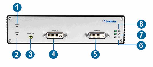
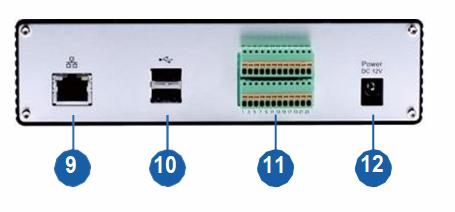
7 2 Overview GV-VS04H / 14 Front View Rear View
8 No. Name Function 1 Video Input 4 plugs for video inputs. 2 Speaker Output A plug for the speaker device. 3 Audio Input Each plug is for 2 audio inputs. 4 Default Button It resets all configurations to their factory settings. See 7 Restoring to Default Settings in the Quick Start Guide. 5 Disk Full/Fault LED This LED is on, indicating the hard drive is full or faulty. 6 Ready LED This LED is on, indicating the GV-Video Server is ready for connection. 7 Power LED This LED is on, indicating the power is supplied. 8 Reset It reboots the GV-Video Server, and keeps all current configurations. 9 USB Port 2 USB ports for installing portable storage devices. 10 Terminal Block The connectors for digital inputs, relay outputs, PTZ cameras, Wiegand device and GPS module control. 11 Ethernet Port A plug for a 10/100 Ethernet or PoE. Note: GV-VS14 does not support PoE function. 12 Power Out A plug to power the camera, by using a DC Male-to-Male Cable, directly through the GV-Video Server. Note: When PoE is applied, you cannot power the camera through the GV-Video Server. 13 Power In A plug to power the GV-Video Server.

9 GV-VS11 Front View Rear View No. Name Function 1 Video Input 1 plug for video input. 2 Default Button It resets all configurations to their factory settings. See 7 Restoring to Default Settings in the Quick Start Guide. 3 Audio Input 1 plug for audio input. 4 Ready LED This LED is on, indicating the GV-Video Server is ready for connection. 5 Power LED This LED is on, indicating the power is supplied. 6 USB Port 1 USB port for installing portable storage device. 7 Ethernet Port A plug for inserting an Ethernet cable to build the network connection. 8 Terminal Block The connectors for digital inputs, digital outputs and PTZ camera controls. 9 Power In A plug to power the GV-Video Server.
10 GV-VS12 Front View Rear View
11 No. Name Function 1 USB Port 1 USB port for installing the portable storage device. 2 Speaker Output A plug for the speaker device. 3 Audio Input 2 plugs for audio inputs. 4 Video Input 2 plugs for video inputs. 5 Power In A plug to power the GV-Video Server. 6 Ethernet Port A plug for inserting an Ethernet cable to build the network connection. 7 USB Port 1 USB port for installing the portable storage device. 8 I/O / PTZ Port A port for digital input, relay output and PTZ camera control. Insert the I/O Cable with RJ-45 Connector to this port. 9 RS-232 Terminal Block The connectors for GPS module control. 10 Default Button It resets all configurations to their factory settings. See 7 Restoring to Default Settings in the Quick Start Guide. 11 Ready LED This LED is on, indicating the GV-Video Server is ready for connection. 12 Power LED This LED is on, indicating the power is supplied.


12 GV-VS2420 / 2400 Front View Rear View No. Name Function 1 Power LED This LED is on, indicating the power is supplied. 2 Ready LED This LED is on, indicating the GV-Video Server is ready for connection. 3 Disk Full/Fault LED This LED is on, indicating the hard drive is full or faulty. 4 Reset It reboots the GV-Video Server, and keeps all current configurations. 5 Default Button It resets all configurations to their factory settings. See 7 Restoring to Default Settings in the Quick Start Guide. 6 Video Input 4 plugs for video inputs. 7 Line Out A plug for Video 1 speaker device. 8 Line In A plug for Video 1 audio input.
13 9 USB Port 2 USB ports for installing portable storage devices. 10 Terminal Block The connectors for digital inputs, relay outputs, and PTZ cameras. See 8 Connecting Auxiliary Devices in the Quick Start Guide. 11 Gigabit Ethernet Port A plug for a 10/100/1000 Base-T Ethernet 12 Power Out A plug to power the camera, by using the optional DC Male-to-Male Cable, directly through the GV-Video Server. 13 Power In A plug for power input. Note: When transmitting video signals over a long distance, it is highly recommended to use 5C-FB coaxial cables or above to minimize the degradation of image quality. The transmission distance should be within 300 m (984 ft).


14 GV-VS2401 Front View Rear View No. Name Function 1 Power LED This LED is on, indicating the power is supplied. 2 Ready LED This LED is on, indicating the GV-Video Server is ready for connection. 3 Disk Full/Fault LED This LED is on, indicating the hard drive is full or faulty. 4 Reset It reboots the GV-Video Server, and keeps all current configurations. 5 Default Button It resets all configurations to their factory settings. See 7 Restoring to Default Settings in the Quick Start Guide. 6 Video Input 4 plugs for video inputs. 7 Audio Out A plug for the speaker device. 8 Audio In Each plug is for 2 audio inputs.
15 9 Gigabit Ethernet Port A plug for a 10/100/1000 Base-T Ethernet 10 USB Port 2 USB ports for installing portable storage devices. 11 Terminal Block The connectors for digital inputs, relay outputs, and PTZ cameras. See 8 Connecting Auxiliary Devices in the Quick Start Guide. 12 Power Out A plug to power the camera, by using the optional DC Male-to-Male Cable, directly through the GV- Video Server. 13 Power In A plug for power input. Note: When transmitting video signals over a long distance, it is highly recommended to use 5C-FB coaxial cables or above to minimize the degradation of image quality. The transmission distance should be within 300 m (984 ft).


16 GV-VS2820 / 2800 Front View Rear View
17 No. Name Function 1 Audio Out A plug for the speaker device. 2 Audio In 4 plugs for max. 8 audio inputs. 3 Video Input 8 plugs for video inputs. 4 Reset It reboots the GV-Video Server and keeps all current configurations. 5 Default Button It resets all configurations to their factory settings. See 7 Restoring to Default Settings in the Quick Start Guide. 6 Disk Full/Fault LED This LED is on, indicating the hard drive is full or faulty. 7 Ready LED This LED is on, indicating the GV-Video Server is ready for connection. 8 Power LED This LED is on, indicating the power is supplied. 9 Gigabit Ethernet Port A plug for a 10/100/1000 Base-T Ethernet 10 USB Port 2 USB ports for installing portable storage devices. 11 Terminal Block The connectors for digital inputs, digital outputs, and PTZ cameras. See 8 Connecting Auxiliary Devices in the Quick Start Guide. 12 Power In A plug for power input. Note: When transmitting video signals over a long distance, it is highly recommended to use 5C-FB coaxial cables or above to minimize the degradation of image quality. The transmission distance should be within 300 m (984 ft).
18 GV-VS21600 Front View 2 3 Rear View 6
19 No. Name Function 1 Reset It reboots the GV-Video Server and keeps all current configurations. 2 Default Button It resets all configurations to their factory settings. See 7 Restoring to Default Settings in the Quick Start Guide. 2 Audio Out A plug for the speaker device. 3 Audio In A DVI plug connected with16 RCA ports for audio inputs. 4 Video Input A DVI plug connected with 16 BNC ports for video inputs. 6 Disk Full/Fault LED 7 Ready LED This LED is on, indicating the hard drive is full or faulty. This LED is on, indicating the GV-Video Server is ready for connection. 8 Power LED This LED is on, indicating the power is supplied. 9 Gigabit Ethernet A plug for a 10/100/1000 Base-T Ethernet Port 10 USB Port 2 USB ports for installing portable storage devices. 11 Terminal Block The connectors for digital inputs, digital outputs and PTZ cameras. See 8 Connecting Auxiliary Devices in the Quick Start Guide. 12 Power In A plug for power input. Note: When transmitting video signals over a long distance, it is highly recommended to use 5C-FB coaxial cables or above to minimize the degradation of image quality. The transmission distance should be within 300 m (984 ft).
20 3 Installing on anetwork Here we use GV-VS04H as an example to demonstrate the basic connections Connect your camera s video output to the BNC video input. 2. Connect the microphone to the RCA audio input using the 3.5 mm Stereo to RCA Cable. 3. Connect the hub or switch on the LAN to the unit s 10/100 Mbps port. 4. Connect power using one of the following methods: Use the supplied power adapter to connect to power. Use the Power over Ethernet (PoE) function to provide power over the network cable. 5. Optionally connect the DC Male-to-Male Cable to power the camera through the GV-Video Server. 6. Wait until both Power and Ready LEDs are on and then you can access its Web interface. See 4. Accessing the GV-Video Server later in the Quick Start Guide.
21 Note: 1. GV-VS11 / 14 / 2420 / 2400 / 2401 / 2800 / 2820 / do not support PoE function. 2. For the users of other models, see Options in 1 Introduction. 3. GV-Video Server cannot work with microphones requiring power from the unit. Use the microphone that has external power supply. 4. When PoE is applied, you cannot power the camera through the GV- Video Server.
22 4 Accessing thegv-videoserver System Requirements To access the Web interface of the GV-Video Server, ensure your PC is in good network connection and use one of the following Web browsers: For GV-VS04H / 11 / 12 / 14 Microsoft Internet Explorer 7.x or later For GV-VS2420 / 2400 / 2401 / 2800 / 2820 / Microsoft Internet Explorer 8.x or later Google Chrome Mozilla Firefox Safari Microsoft Edge Note: 1. For the users of Internet Explorer 8 or later, additional settings are required. For details, see Appendix A in GV-Video Server User s Manual on the GeoVision download page: 2. Internet Explorer 10 is only supported by GV-VS11 version 1.05, GV-VS12 version 1.09 and GV-VS14 version For users of non-ie browsers using GV-VS2420 / 2400 / 2401 / 2800 / 2820 / 21600, download GV-Web Viewer to access full functioning user interface. For details, see 3.1 Accessing Your Surveillance Images in GV- Video Server User s Manual from the GeoVision download page:

23 Checking the IP Address and Logging In By default, the IP address of your GV-Video Sever is assigned by the DHCP server unless your router does not support DHCP. In this case, the default IP address will be Follow the steps below to look up the IP address and access the Web interface. 1. Install the GV-IP Device Utility program from GeoVision download page: Note: The PC installed with GV-IP Device Utility must be under the same LAN as the GV-Video Server you wish to configure. 2. On the GV-IP Utility window, click the button to search for the IP devices connected in the same LAN. Click the Name or Mac Address column to sort.
24 3. Find the GV-Video Server with its Mac Address to see the IP address. 4. To login, type the IP address in your Web browser. A dialog box appears. 5. Type the default username and password admin. 6. Click Apply to access the Web interface. 7. When accessing the GV-Video Server for the first time, you must set your browser to allow a one-time installation of GeoVision s ActiveX component onto your computer. Note: If your router does not support DHCP, the default IP address will be In this case, it is strongly suggested to modify the IP address to avoid IP address conflict with other GeoVision IP device on the same LAN. For details, see 2.3 Changing the IP Address, GV-Video Server User s Manual.

25 5 The Web Interface
26 No. Name Function 1 Play Plays live video. 2 Stop Stops playing video. 3 Microphone Talks to the surveillance area from the local computer. 4 Speaker Listens to the audio around the camera. 5 Snapshot Takes a snapshot of live video. 6 File Save Records live video to the local computer. 7 Full Screen Switches to full screen view. Right-click the image to have these options: Snapshot, PIP, PAP, Zoom In and Zoom Out. 8 Control Panel Displays the camera information, video settings, audio data rate, I/O device status, images captured upon alarm and GPS location of the camera. 9 I/O Control Starts I/O Control Panel or Visual Automation. 10 PTZ Control Starts PTZ Control Panel and Visual PTZ. 11 Change Camera Sets the desired camera for display. 12 Show System Menu Brings up these functions: Alarm Notify, Video and Audio Configuration, Remote Config, Show Camera Name and Image Enhance. For detailed operations, see Accessing the GV-Video Server, Chapter 3, GV-Video Server User's Manual.
27 6 Upgrading System Firmware GeoVision will periodically release the updated firmware on the website. To load the new firmware into the GV-Video Server, read the important notes below and follow the instructions. Important: 1. While the firmware is being updated, A) the power supply must not be interrupted, and B) do not unplug the Ethernet cable if the cable is the source of power supply (Power over Ethernet or PoE supported). 2. Do not turn the power off within 10 minutes after the firmware is updated. 3. If you use the IP Device Utility for firmware upgrade, the computer used to upgrade firmware must be under the same network as the GV-Video Server.
 saved at your local computer. 3. Click the Upgrade button to start the upgrade.")
28 1. In the Live View window, click the Show System Menu button and select Remote Config. This dialog box appears. 2. Click the Browse button to locate the firmware file (.img) saved at your local computer. 3. Click the Upgrade button to start the upgrade. WARNING: The interruption of power supply during updating causes not only update failures but also damages to your GV-Video Server. In this case, please contact our sales representatives and send your device back to GeoVision for repair. For details on upgrading system firmware, see Advanced Applications, Chapter 6, GV-Video Server User's Manual.

29 7 Restoring to Default Settings You can restore the camera to factory default settings using the Web interface or directly on the GV-Video Server. Using the Web Interface: 1. On the left menu of Web interface, select Management and select Tools. The Additional Tools dialog appears. 2. Click the Load Default button in the System Settings section.
30 Directly on the GV-Video Server: GV-VS04H / Press and then release the Reset button immediately. 2. Press and hold the Load Default button until all 3 LEDs (Power, Ready and Disk Full/Fault) are on. This may take about 30 seconds. 3. Release the Load Default button. The process of loading default values is complete, and the GV-Video Server starts rebooting itself with all 3 LEDs turned off. 4. Wait until the Power and Ready LEDs turn on again. After this, all the settings are returned to default values.

31 GV-VS GV-VS Unplug and plug the power cable to start. 2. Press and hold the Default button until the Ready LED blinks. This may take about 30 seconds. The Ready LED will blink twice. 3. Release the Default button. The process of loading default values is complete, and the GV-Video Server starts rebooting itself with the 2 LEDs turned off. 4. Wait until the Power and Ready LEDs turn on again. After this, all the settings are returned to default values.


32 GV-VS2420 / GV-VS2401 GV-VS2820 /
33 GV Press and hold the Default button until the Ready LED blinks. This may take up to 10 seconds. The Ready LED will blink twice. 2. Release the Default button. The process of loading default values is complete, and the GV-Video Server starts rebooting itself with the Ready LED turned off. 3. Wait until the Ready LED turns on again. After this all the settings are returned to default values Note: Before the Ready LED is on again, do not unplug the power cable; otherwise the loading of default values will fail.
34 8 Connecting Auxiliary Devices GV-VS04H / 14 / 2420 / 2400 / 2401 / 2820 / 2800 / GV-VS04H / 14 / 2420 / 2400 / 2401 The 16-pin terminal block, located on the rear panel, provides interfaces for four digital inputs, four relay outputs, an RS-485 interface, a Wiegand interface, a GPS interface or auxiliary power. The terminal block can be used to develop applications for motion detection, event alerts via and FTP, center monitoring by Center V2 and Vital Sign Monitor, PTZ control or Wiegandinterface card reader, and a variety of other functions
35 Pin Assignment The table below lists the pin assignment for the terminal block. GV-VS04H / 14 Pin Function Pin Function 1 Relay Output 1 9 DC 5V Out for GV-Relay Module, or GPS Module 2 Digital Input 1 10 Ground, or GPS Ground 3 Relay Output 2 11 RS Digital Input 2 12 Wiegand D0, or GPS RX 5 Relay Output 3 13 RS Digital Input 3 14 Wiegand D1, or GPS TX 7 Relay Output 4 15 Ground 8 Digital Input 4 16 DC 12V Out for Wiegand Card Reader Note: To connect the GPS module, use Pin 9 for power supply, Pin 10 for ground, Pin 12 for GPS RX and Pin 14 for GPS TX. GV-VS2420 / 2400 / 2401 Pin Function Pin Function 1 Digital Output 1 9 DC 5V Out for GV-Relay Module 2 Digital Input 1 10 Ground 3 Digital Output 2 11 RS Digital Input 2 12 N/A 5 Digital Output 3 13 RS Digital Input 3 14 N/A 7 Digital Output 4 15 Ground 8 Digital Input 4 16 DC 12V Out

36 GV-VS2820 / 2800 / The 24-pin terminal block, located on the rear panel, provides interfaces for eight digital inputs, eight digital outputs, an RS-485 interface and auxiliary power. The terminal block can be used to develop applications for motion detection, event alerts via and FTP, center monitoring by Center V2 and Vital Sign Monitor, PTZ control and a variety of other functions
37 GV-VS2820 / 2800 / Pin Function Pin Function 1 Digital Output 1 13 Digital Output 7 2 Digital Input 1 14 Digital Input 7 3 Digital Output 2 15 Digital Output 8 4 Digital Input 2 16 Digital Input 8 5 Digital Output 3 17 Ground 6 Digital Input 3 18 Ground 7 Digital Output 4 19 DC 5V Out for GV-Relay Module 8 Digital Input 4 20 RS Digital Output 5 21 Ground 10 Digital Input 5 22 RS Digital Output 6 23 DC 12V Out 12 Digital Input 6 24 Ground
38 GV-VS11 The terminal block on the rear panel of GV-VS11 provides one digital input and output, an RS-485 interface and auxiliary power V Pin Assignment DI DO G The table below lists the pin assignment for the terminal block. Pin RS-485- RS V DI DO G Function RS-485- RS-485+ DC 5V Out Digital Input Digital Output Ground
39 GV-VS12 GV-VS12 provides I/O Cable with RJ-45 Connector for extensible connection to I/O devices and PTZ cameras. A RJ-45 connector and a bundle of shielded wires are on each end of the cable. Pin Assignment The table below lists the pin assignment for the shielded wires of the I/O Cable with RJ-45 Connector. Pin Wire Function 1 Brown Digital Out 1 2 White with Brown Stripe Digital Out 2 3 White with Green Stripe Ground 4 White with Blue Stripe Digital In 1 5 Blue Digital In 2 6 Green Ground 7 Orange RS White with Orange Stripe RS-485 +
40 RS-232 Terminal Block The RS-232 terminal block on GV-VS12 is mainly used for connecting to a GPS module. RS232 TX RX G 5V Pin TX RX G 5V Function GPS RX (Receive) GPS TX (Transmit) Ground DC 5V Out Note: To ensure the connection to the GV-VS12, the GPS RX must be connected to the TX pin, and the GPS TX must be connected to the RX pin. For details, see Auxiliary Device Connectors, Chapter 9, GV-Video Server User's Manual on the GeoVision download page: 9F, No. 246, Sec. 1, Neihu Rd., Neihu District, Taipei, Taiwan Tel: Fax: support@geovision.com.tw
Quick Start Guide. GV-Video Server
 Quick Start Guide GV-Video Server Thank you for purchasing GV-Video Server. This guide is designed to assist the new user in getting immediate results from the GV-Video Server. For advanced information
Quick Start Guide. GV-Video Server. 1 Introduction. Packing List
 Introduction Quick Start Guide GV-Video Server Welcome to the GV-Video Server Quick Start Guide. In the following sections, you will learn about the basic installations and configurations of the GV-Video
GV-Video Server. User's Manual
 GV-Video Server User's Manual Before attempting to connect or operate this product, please read these instructions carefully and save this manual for future use. VS-UM-B 2018 GeoVision, Inc. All rights
Quick Start Guide. 1 Introduction. GV-Box Camera GV-BX120D / 220D / 320D. Packing List
 1 Introduction Welcome to the GV-Box Camera Quick Start Guide. In the following sections, you will learn about the basic installations and configurations of the GV-Box camera (GV-BX120D / 220D / 320D).
Quick Start Guide. GV-Fisheye IP Camera. 1 Introduction. Packing List
 1 Introduction Welcome to the GV-Fisheye IP Camera Quick Start Guide. In the following sections, you will learn the basic installations and configurations of GV-Fisheye IP Camera. For the detailed user
GV-Video Server. User's Manual
 GV-Video Server User's Manual Before attempting to connect or operate this product, please read these instructions carefully and save this manual for future use. VS2420-2400-A 2016 GeoVision, Inc. All
The Vision of Security
 Quick Start Guide GV-SNVR System The Vision of Security Thank you for purchasing GV-SNVR. This guide is designed to assist the new user in getting immediate results from the GV-SNVR. For advanced information
Quick Start Guide. GV-CS1320 Camera Access Controller
 Quick Start Guide GV-CS1320 Camera Access Controller Thank you for purchasing GV-CS1320 Camera Access Controller. This guide is designed to assist the new user in getting immediate results from the controllers.
GV-Video Server. User's Manual
 GV-Video Server User's Manual Before attempting to connect or operate this product, please read these instructions carefully and save this manual for future use. VS04H.VS12V106.VS11V102.VS14V10-B 2012
GV-Video Server. User's Manual
 GV-Video Server User's Manual Before attempting to connect or operate this product, please read these instructions carefully and save this manual for future use. 2009 GeoVision, Inc. All rights reserved.
Quick Start Guide GV-Panoramic PTZ Camera
 Quick Start Guide GV-Panoramic PTZ Camera Before attempting to connect or operate this product, please read these instructions carefully and save this manual for future use. PPTZV10-QG-A 2016 GeoVision,
Quick Start Guide. GV-IP Speed Dome ISD QG-B
 Quick Start Guide GV-IP Speed Dome Before attempting to connect or operate this product, please read these instructions carefully and save this manual for future use. ISD220200-QG-B 2013 GeoVision, Inc.
Quick Start Guide. GV-Fisheye IP Camera
 Quick Start Guide GV-Fisheye IP Camera Thank you for purchasing GV-Fisheye IP Camera. This guide is designed to assist the new user in getting immediate results from the GV-Fisheye IP Camera. For advanced
GV-I/O Box 4E. Contents
 GV-I/O Box 4E Contents 1.1 Key Features... 2 1.2 System Requirements... 2 1.3 Packing List... 2 1.4 Overview... 3 1.5 Connecting to PC... 4 1.5.1 RS-485 Wiring... 4 1.6 Assigning Device ID to GV-I/O Box
Quick Start Guide. GV-Fisheye IP Camera
 Quick Start Guide GV-Fisheye IP Camera Thank you for purchasing GV-Fisheye IP Camera. This guide is designed to assist the new user in getting immediate results from the GV-Fisheye IP Camera. For advanced
GV-Card Reader. User s Manual
 GV-Card Reader User s Manual Before attempting to connect or operate this product, please read these instructions carefully and save this manual for future use. READER-B 2016 GeoVision, Inc. All rights
Zavio P5111/ P5116/ P5210 Quick Installation Guide
 86085M2000010 Zavio P5111/ P5116/ P5210 Quick Installation Guide Installation Steps Please follow the installation steps below to set up your P5111 / P5116/ P5210 Day/Night Pan/Tilt IP Camera. Check the
Quick Start Guide. GV-IP Speed Dome ISD-QG-G
 Quick Start Guide GV-IP Speed Dome Before attempting to connect or operate this product, please read these instructions carefully and save this manual for future use. ISD-QG-G 2015 GeoVision, Inc. All
Quick Start Guide. GV-Fisheye IP Camera
 Quick Start Guide GV-Fisheye IP Camera Thank you for purchasing GV-Fisheye IP Camera. This guide is designed to assist the new user in getting immediate results from the GV-Fisheye IP Camera. For advanced
Industrial PoE Plus Outdoor IR IP Camera ICA-2250VT
 Industrial PoE Plus Outdoor IR IP Camera ICA-2250VT Quick Installation Guide Table of Contents Chapter 1. Introduction... 3 1.1 Before Installation... 3 1.2 System Requirements... 3 Chapter 2. Physical
Contents. GV-I/O Box 8 Ports Key Features Compatible Software Packing List Overview DIP Switch...
 Contents GV-I/O Box 8 Ports...2 1. Key Features... 2 2. Compatible Software... 2 3. Packing List... 2 4. Overview... 3 5. DIP Switch... 3 6. Connections to PC... 4 6.1 Installing USB Driver... 5 6.2 Assigning
GV-IPCam H.264. Hardware Manual. Vandal Proof IP Dome Target Vandal Proof IP Dome
 GV-IPCam H.264 Hardware Manual Vandal Proof IP Dome Target Vandal Proof IP Dome Before attempting to connect or operate this product, please read these instructions carefully and save this manual for future
GV-SNVR1611. Introduction
 GV-SNVR1611 Introduction The GV SNVR1611 is an H.264/H.265 Linux embedded Standalone Network Video Recorder which records video files directly to the internal hard drive, supporting up to 16 channels of
The GV-I/O Box 16 Ports provides 16 inputs and 16 relay outputs, and supports both DC and AC output voltages.
 GV-I/O Box 16 Ports The GV-I/O Box 16 Ports provides 16 inputs and 16 relay outputs, and supports both DC and AC output voltages. Key Features 16 inputs and 16 outputs are provided. Up to 9 pieces of GV-I/O
GV-IP Decoder Box Plus User s Manual
 GV-IP Decoder Box Plus User s Manual Before attempting to connect or operate this product, please read these instructions carefully and save this manual for future use. DBPV10-UM-A 2015 GeoVision, Inc.
GV-RK1352 and GV-R1352 Card Reader
 GV-RK1352 and GV-R1352 Card Reader The GV-RK1352 and GV-R1352 are card readers designed to recognize identifications cards. GV-RK1352 comes with keypad, allowing it to also recognize PIN codes. Featured
Quick Start Guide. GV-Redundant Server / GV-Failover Server V Introduction. Packing List
 1 Introduction Quick Start Guide GV-Redundant Server / GV-Failover Server V1.02 Welcome to the GV-Redundant Server / Failover Server Quick Start Guide. In the following sections, you will be guided through
GV-SNVR0811. Introduction
 - 1 - GV-SNVR0811 Introduction The GV SNVR0811 is an H.264/H.265 Linux embedded Standalone Network Video Recorder which records video files directly to the internal hard drive, supporting up to 8 channels
P6210 PN: 86085A A
 P6210 1 PN: 86085A1000010 86085A1000000 Zavio P6210 Quick Installation Guide Please follow the installation steps below to set up P6210 Pan/Tilt IR Dome IP Camera. Check the package contents against the
GV-IP LPR Camera. User's Manual. GV-LPC2210 GV-LPC2211 GV-LPC2011 GV-LPR1200 GV-LPC1200 GV-LPC1100 GV-IP LPR Cam 5R
 GV-IP LPR Camera User's Manual GV-LPC2210 GV-LPC2211 GV-LPC2011 GV-LPR1200 GV-LPC1200 GV-LPC1100 GV-IP LPR Cam 5R Before attempting to connect or operate this product, please read these instructions carefully
B-33. Hardware and Install Manual. (DC 12V / PoE)
") B-33 Hardware and Install Manual (DC 12V / PoE) Table of Contents Precautions 3 Safety Instructions... 4 Introduction 6 Package Contents... 6 Physical Description... 7 Installation Procedures 9 Step 1:
B-33 Hardware and Install Manual (DC 12V / PoE) Table of Contents Precautions 3 Safety Instructions... 4 Introduction 6 Package Contents... 6 Physical Description... 7 Installation Procedures 9 Step 1:
GV-SNVR1600. Introduction
 - 1 - GV-SNVR1600 Introduction The GV SNVR1600 is a Linux embedded Standalone Network Video Recorder which records video files directly to the internal hard drive, supporting up to 16 channels of GV IP
IN-E1004 Encoder Hardware Manual
 IN-E1004 Encoder Hardware Manual 2014/06/03 Table of Contents Precautions... 4 Safety Instructions... 6 Introduction... 7 The List of Models... 7 Package Contents... 8 Physical Description... 9 Mounting
Quick Start Guide GV-VMS
 Quick Start Guide GV-VMS Thank you for purchasing GV-VMS. This guide is designed to assist the new user in getting immediate results from the GV-VMS. For advanced information on how to use the GV-VMS,
Quick Start Guide. GV-Recording Server. 1 Introduction. Packing List
 1 Introduction Quick Start Guide GV-Recording Server Welcome to the GV-Recording Server Quick Start Guide. This quick guide will guide you through the basic installation of GV-Recording Server, connecting
F3102 / F3107 / F3110 / F3115 / F3210 / F3215 PN: 86085K K
 F3102 / F3107 / F3110 / F3115 / F3210 / F3215 86085K3000020 PN: 86085K3000030 Zavio F3102/F3107/F3110/F3115/F3210/F3215 Quick Installation Guide Please follow the installation steps below to set up F3102
D G
 D7210 0 86085G6000010 Zavio D7210 Quick Installation Guide Please follow the installation steps below to set up your D7210 Dome IP Camera. Check the package contents against the list below. See P.1 Physical
D4210 PN: 86085A
 D4210 1 PN: 86085A2000000 Zavio D4210 Quick Installation Guide Please follow the installation steps below to set up D4210 IR Dome IP Camera. Check the package contents against the list below. See P.1
2M Outdoor Motorized Bullet Camera
 2M Outdoor Motorized Bullet Camera 8608586000010 Quick Installation Guide Please follow the installation steps below to set up your 2MP Bullet IP Camera. Check the package contents against the list below.
Outdoor Hemispheric Mounting on the Ceiling with Gang Box (Face Down)
") Outdoor Hemispheric Mounting on the Ceiling with Gang Box (Face Down) Installation Guide For Models: KCM-7911 2014/01/17 Table of Contents Installation Procedures... 3 Step 1: Prepare for Waterproof Installation...
Outdoor Hemispheric Mounting on the Ceiling with Gang Box (Face Down) Installation Guide For Models: KCM-7911 2014/01/17 Table of Contents Installation Procedures... 3 Step 1: Prepare for Waterproof Installation...
mygvcloud Quick Start Guide
 mygvcloud Quick Start Guide EN mygvcloudv104-qg-d-en 2016 GeoVision, Inc. All rights reserved. Under the copyright laws, this manual may not be copied, in whole or in part, without the written consent
QUICK START GUIDE. Megapixel Network Camera for Video Surveillance.
 Version 3.0 QUICK START GUIDE Megapixel Network Camera for Video Surveillance 2016 Camerawelt www.camerawelt.com Table of Contents 1. Package Contents...2 2. Cautions... 2 3. System Requirements... 2
V3x Series Encoder Hardware Manual
 V3x Series Encoder Hardware Manual V31, V32 2016/05/31 Table of Contents Precautions... 3 Safety Instructions... 5 Introduction... 6 The List of Models... 6 Package Contents... 7 Physical Description...
F3102 / F3107 / F3110 / F3115 / F3210 / F3215 PN: 86085K K
 F3102 / F3107 / F3110 / F3115 / F3210 / F3215 0 86085K3000020 PN: 86085K3000020 Zavio F3102/F3107/F3110/F3115/F3210/F3215 Quick Installation Guide Please follow the installation steps below to set up
Zoom Box Camera Series Hardware Manual
 Zoom Box Camera Series Hardware Manual E213, E215, E219, E223 2016/02/16 Table of Contents Precautions... 4 Safety Instructions... 6 Introduction... 7 The List of Models... 7 Package Contents... 8 Physical
Zavio M511E / M511W Quick Installation Guide
 Zavio M511E / M511W Quick Installation Guide Please follow the installation steps below to set up your M511E / M511W IP Camera. Check the package contents against the list below. See P.1 Physical overview.
CMOS/Mega-Pixel CMOS/CCD Internet Camera ICA-230 / ICA-M230 / ICA-501. Quick Installation Guide
 CMOS/Mega-Pixel CMOS/CCD Internet Camera ICA-230 / ICA-M230 / ICA-501 Quick Installation Guide Table of Contents Chapter 1. Introduction... 3 1.1 Before Installation... 3 1.2 System Requirements... 3 1.3
GV-Fisheye IP Camera
 GV-Fisheye IP Camera User's Manual Before attempting to connect or operate this product, please read these instructions carefully and save this manual for future use. FEV114-UM-A 2018 GeoVision, Inc. All
GV-IPCam H.264. Hardware Manual. Bullet Camera Ultra Bullet Camera Target Bullet Camera
 GV-IPCam H.264 Hardware Manual Bullet Camera Ultra Bullet Camera Target Bullet Camera Before attempting to connect or operate this product, please read these instructions carefully and save this manual
VK2-ENCODER. Installation Guide
 VK2-ENCODER Installation Guide This page is intentionally left blank 1. Product Description This manual applies to the VIP Kit2 Camera VK2-ENCODER The VK2-ENCODER supports the network service for an existing
Quick Start Guide V5.1.
 Quick Start Guide V5.1 1 Quick Start Guide Table of Content 1. Package Contents...1 2. Cautions... 1 3. System Requirements... 1 4. Hardware Overview... 2 4.1 Mini Dome Network Camera...2 4.2 IR Mini
2 Mega-Pixel H.264 Box IP Camera ICA-HM125. Quick Installation Guide. Version 1.0
 2 Mega-Pixel H.264 Box IP Camera ICA-HM125 Quick Installation Guide Version 1.0 Table of Contents Chapter 1. Introduction... 3 1.1 Before Installation... 3 1.2 System Requirements... 3 Chapter 2. Physical
Encoder Firmware V User s Manual. Outdoor PTZ Camera Hardware Manual KCM /05/09.
 Encoder Firmware V4.06.09 User s Manual Outdoor PTZ Camera Hardware Manual KCM-8211 2013/05/09 1 Table of Contents Precautions... 3 Introduction... 4 List of Models... 4 Package Contents... 5 Safety Instructions...
WELCOME. For customer support or any inquiries, please visit our web site at or contact us at
 WELCOME Congratulations on purchasing the GBF Smart Four Wire Intercom System. Our factory engineers were the first to enable multiple security cameras being monitored through a smart mobile device and
IS-DM240, V User Manual. Ver 1.0
 IS-DM240, V User Manual Ver 1.0 Sentry360 2014 Table of Contents 1. Overview... 3 1.1 Features... 3 1.2 Package Contents... 4 1.3 Dimensions... 6 1.4 Switch / Connector Definition... 7 2. Camera Cabling...
GV-IP Camera. Hardware Manual. Box Camera Ultra Box Camera Arctic Box Camera Target Box Camera
 GV-IP Camera Hardware Manual Box Camera Ultra Box Camera Arctic Box Camera Target Box Camera Before attempting to connect or operate this product, please read these instructions carefully and save this
Zoom Box Camera Series Hardware Manual
 Zoom Box Camera Series Hardware Manual B21, B22, B23, B24, B25, B27, B210, B214, B215, E210 I24, I25, I27, I28, I29 2017/07/04 Table of Contents Precautions... 4 Safety Instructions... 6 Introduction...
Panoramic Fisheye IP Camera. Quick Installation Guide
 Panoramic Fisheye IP Camera Quick Installation Guide 8608595330000 Please follow the installation below steps to set up Panoramic Fisheye IP Camera. Check the package contents against the list below.see
2M IR Mini Dome Quick Installation Guide
 1 2M IR Mini Dome Quick Installation Guide Please follow the installation steps below to set up 2M IR Mini Dome IP Camera. Check the package contents against the list below. See P.1 Physical overview.
GV-DSP LPR User's Manual
 GV-DSP LPR User's Manual Before attempting to connect or operate this product, please read these instructions carefully and save this manual for future use. DSP23V106-A 2011 GeoVision, Inc. All rights
Quick Install Guide. Model: PLC-223W, PLC-233W
 Quick Install Guide Model: PLC-223W, PLC-233W This installation guide provides basic instructions for installing the PLC-213W/ PLC-223W/PLC-233W indoor wireless IP camera on your network. By following
GV-Fisheye IP Camera H.264
 GV-Fisheye IP Camera H.264 User's Manual Before attempting to connect or operate this product, please read these instructions carefully and save this manual for future use. FETIV212-A 2014 GeoVision, Inc.
Version 2.6 Quick Start Guide VV
 VV Table of Contents 1. Package Contents... 2 2. Cautions... 3 3. System Requirements... 3 4. Hardware Overview... 4 4.1 Mini Dome Network Camera... 4 4.2 IR Mini Dome Network Camera... 5 4.3 Vandal-proof
Quick Installation Guide
 Quick Installation Guide DL-200 Cellular Data logger V1.2_201610 TABLE OF CONTENTS CHAPTER 1 INTRODUCTION... 4 1.1 CONTENTS LIST... 5 1.2 HARDWARE INSTALLATION... 6 1.2.1 WARNING... 6 1.2.2 SYSTEM REQUIREMENTS...
GV-Recording Server. User's Manual V RSV13-A-EN
 GV-Recording Server User's Manual V1.3.0.0 RSV13-A-EN 2016 GeoVision, Inc. All rights reserved. Under the copyright laws, this manual may not be copied, in whole or in part, without the written consent
SVT-WIFI Video Intercom System C
 SVT-WIFI Video Intercom System C User Manual Please read this user manual prior to installing the system, and keep it well for future use. CONTENTS 1. Parts and Functions... 1 2. Terminal Descriptions...
ALI-NVR5100P Series Embedded Network Video Recorder Quick Setup Guide
 ALI-NVR5100P Series Embedded Network Video Recorder Quick Setup Guide This quick setup guide provides instructions to initially setup and use the ALI-NVR5116P and ALI-NVR5132P network video recorders (NVRs).
ZAVIO Indoor Box Camera. Quick Installation Guide
 ZAVIO Indoor Box Camera Quick Installation Guide 1 Quick Installation Guide Please follow the installation steps below to set up your IP camera. Check the package contents with the list below. See P.2
Quick Start Guide.
 1 Table of Content 1. Package Contents...1 2. Cautions... 1 3. System Requirements... 1 4. Hardware Overview... 2 4.1 Mini Dome Network Camera...2 4.2 IR Mini Dome Network Camera...3 4.3 Vandal-proof
IS-DM320, HB User Manual. Ver 1.0
 IS-DM320, HB User Manual Ver 1.0 Sentry360 2014 Table of Contents 1. Overview... 3 1.1 Features... 3 1.2 Package Contents... 4 1.3 Dimensions... 5 1.4 Connectors... 6 2. Camera Cabling... 7 2.1 Connect
Roughneck V920D Series Camera Domes XX Quick Guide
 Quick Guide XX258-20-06 Roughneck V920D Series Camera Domes Vicon Industries Inc. Tel: 631-952-2288 Fax: 631-951-2288 Toll Free: 800-645-9116 24-Hour Technical Support: 800-34-VICON (800-348-4266) UK:
Video Decoder Setup Guide
 Package Content Video Decoder Setup Guide Inspect the packaging carton. Make sure the Video Decoder is properly delivered. Remove all items from the box and make sure the box contains the following items.
5.5 AS Layout. GeoVision Technical Handbook 77
 5.5 AS400 5.5.1 Layout GeoVision Technical Handbook 77 5.5.2 Wiegand Reader Connection AS400 supports up to eight Wiegand 26 ~ 64bit readers Wiegand connection has a distance limitation of 30m (~ 100ft)
Outdoor Dome. Mounting on a Tilted Wall with Gang Box (Face Down / Face Forward) Installation Guide. For Models: B81, B84, B85, B /01/13
 Installation Guide. For Models: B81, B84, B85, B /01/13") Outdoor Dome Mounting on a Tilted Wall with Gang Box (Face Down / Face Forward) Installation Guide For Models: B81, B84, B85, B87 2014/01/13 Table of Contents Installation Procedures... 3 Step 1: Prepare
Outdoor Dome Mounting on a Tilted Wall with Gang Box (Face Down / Face Forward) Installation Guide For Models: B81, B84, B85, B87 2014/01/13 Table of Contents Installation Procedures... 3 Step 1: Prepare
Motorized Full-HD IR VP Dome Network Camera
 Quick Installation Guide Motorized Full-HD IR VP Dome Network Camera Please read this manual thoroughly before use, and keep it handy for future reference. Quick Installation Guide 1. Description The Network
HVG400. Installation Guide
 HVG400 Installation Guide September 2013 Trademarks & Copyright Trademarks All trademarks mentioned in this manual are the sole property of their respective manufacturers. Copyright Ltd., Jerusalem, Israel
User Guide. V and V Series Network Panoramic Cameras XX Vicon Industries Inc. Tel: ) Fax:
 Fax:") User Guide V9360-6 and V9360-12 Series Network Panoramic Cameras XX289-10-00 Vicon Industries Inc. does not warrant that the functions contained in this equipment will meet your requirements or that the
User Guide V9360-6 and V9360-12 Series Network Panoramic Cameras XX289-10-00 Vicon Industries Inc. does not warrant that the functions contained in this equipment will meet your requirements or that the
GV-Hot Swap Surveillance System V5 (Rev. B)
") GV-Hot Swap Surveillance System V5 (Rev. B) User s Manual DVRHV5-UM-T 2015 GeoVision, Inc. All rights reserved. Under the copyright laws, this manual may not be copied, in whole or in part, without the
GV-Hot Swap Surveillance System V5 (Rev. B) User s Manual DVRHV5-UM-T 2015 GeoVision, Inc. All rights reserved. Under the copyright laws, this manual may not be copied, in whole or in part, without the
ZAVIO Outdoor IR Mini Dome. Quick Installation Guide
 ZAVIO Outdoor IR Mini Dome Quick Installation Guide 0 Quick Installation Guide Please follow the installation steps below to set up your IP Camera. Check the package contents with the list below. See P.1
1-channel MPEG-4 Video Decoder ACD Ver Quick Installation Guide
 1-channel MPEG-4 Video Decoder ACD-3100 Ver. 090330 Quick Installation Guide 1 1 Getting Started 1.1 PACKAGE CONTENTS ACD-3100 Warranty Card Product CD Terminal Blocks & Screws Power Adaptor (Option)
Network Video Recorder Quick Operation Guide
 Network Video Recorder Quick Operation Guide UD.6L0202B1351A01 TABLE OF CONTENTS NVR Pre-Installation... 2 NVR Installation... 2 Hard Disk Installation... 2 Front Panels... 6 DS-9500NI-ST/RT Front Panel...
B5010/ B5111/ B
 B5010/ B5111/ B5210 0 8608551000030 Zavio B5010/ B5111/ B5210 Quick Installation Guide Please follow the installation steps below to set up your B5010/ B5111/ B5210 Bullet IP Camera. Check the package
GV-Hot Swap Surveillance System
 Quick Start Guide The Vision of Security GV-Hot Swap Surveillance System V5 (Rev. B) RoHS Listed Product including appearances and images are samples and for reference only. Features and specifications
GV-Keyboard. User's Manual V2.0
 GV-Keyboard User's Manual V2.0 Before attempting to connect or operate this product, please read these instructions carefully and save this manual for future use. 2007 GeoVision, Inc. All rights reserved.
2 Mega-Pixel Fish-eye Panorama IP Camera ICA-HM830. Quick Installation Guide
 2 Mega-Pixel Fish-eye Panorama IP Camera ICA-HM830 Quick Installation Guide Table of Contents Chapter 1. Introduction... 3 1.1 Before Installation... 4 1.2 System Requirements... 4 Chapter 2. Physical
MOXA VPort 2110/2140/2141 Video Server Quick Installation Guide
 MOXA VPort 2110/2140/2141 Video Server Quick Installation Guide Third Edition, July 2006 MOXA Networking Co., Ltd. Tel: +886-2-2910-1230 Fax: +886-2-2910-1231 www.moxa.com support@moxanet.com (Worldwide)
F Series Indoor Fixed IP Camera. Quick Start Guide
 F Series Indoor Fixed IP Camera Quick Start Guide Welcome Thank you for purchasing our IP camera! Before install and use the IP camera, please read the following section carefully. Please keep this start
Quick Installation Guide
 Quick Installation Guide Full HD WDR Day & Night Outdoor Network Camera This document will guide you through the basic installation process for your new D-Link Network Camera. DCS-7513 Documentation also
MGate 5111 Quick Installation Guide
 MGate 5111 Quick Installation Guide Edition 1.0, December 2017 Technical Support Contact Information www.moxa.com/support Moxa Americas: Toll-free: 1-888-669-2872 Tel: 1-714-528-6777 Fax: 1-714-528-6778
Full HD WDR Mini Dome IP Camera
 Full HD WDR Mini Dome IP Camera User s Manual DN-16086 Ver. 1.0 Table of Contents 1. Overview... 2 1.1 Features... 2 1.2 Package Contents... 3 1.3 Dimensions... 4 1.4 Installation... 5 1.5 Connectors...
Zavio F3100 / F3105 Quick Installation Guide
 Zavio F3100 / F3105 Quick Installation Guide Please follow the installation steps below to set up F3100 / F3105 IP Camera. Check the package contents against the list below. See P.1 Physical overview.
Falcon SM200 Series Camera
 Falcon Series Camera Quick Start Guide Package Contents Camera with Mount Base 1 Flexible Clamp with Fixing Screws 1 Power Adapter 1 Wall Mounting Screws 1 Terminal Block for Alarm I/O 1 Quick Start Guide
VIP2C1N / VIP2C1P HD Mini Cube Network Camera
 Quick Installation Guide VIP2C1N / VIP2C1P HD Mini Cube Network Camera Please read this manual thoroughly before use, and keep it handy for future reference. 1. Description The Network Camera supports
Lite H.264 DVR Setup Guide
 Package Content Lite H.264 DVR Setup Guide Inspect the packaging carton. Make sure the Lite H.264 DVR is properly delivered. Remove all items from the box and make sure the box contains the following items.
TIME SERVER NETSILON. Quick start.
 TIME SERVER NETSILON Quick start This document refers to the following products: 907,900 NETSILON 7 (100-240 VAC) 907,901 NETSILON 7 (18-36 VDC) 907,902 NETSILON 7 (100-240 VAC + 18-36 VDC) www.bodet-time.com
8/16/32-Ch Network Video Recorder NVR Series
 8/16/32-Ch Network Video Recorder NVR Series Quick Installation Guide Table of Contents Chapter 1. Introduction...3 1.1 Before Installation...3 Chapter 2. Physical Description and Installation...4 2.1
UTM Content Security Gigabit Gateway CS-950
 UTM Content Security Gigabit Gateway CS-950 Quick Installation Guide Table of Contents 1. Package Contents... 3 2. Hardware Introduction... 4 2.1 Hardware Interface... 4 2.2 Hardware Installation... 6
GV-IPCam H.264. Hardware Manual. Cube Camera Mini Fixed Dome Mini Fixed Rugged Dome Target Mini Fixed Dome Target Mini Fixed Rugged Dome
 GV-IPCam H.264 Hardware Manual Cube Camera Mini Fixed Dome Mini Fixed Rugged Dome Target Mini Fixed Dome Target Mini Fixed Rugged Dome Before attempting to connect or operate this product, please read
Quick Install Guide. For Bullet HD Outdoor IP Camera. Model: PLC-325PW, PLC-335PW
 Quick Install Guide For Bullet HD Outdoor IP Camera Model: PLC-325PW, PLC-335PW This installation guide provides basic instructions for installing the PLC-325PW and PLC-335PW Outdoor Waterproof IP camera
4 Channel Mobile CCTV Recorder with GPS INTRODUCTION
 4 Channel Mobile CCTV Recorder with GPS INTRODUCTION The four channel GV Compact DVR V3 is a mobile video recorder, simultaneously displaying real time images from four cameras. The recording frame rate