FEATURES Supports following ST upsd3200 family of microcontrollers ( both package of QFP52 and QFP80)
|
|
|
- Kathleen Ada Baker
- 5 years ago
- Views:
Transcription
1 ME-3200 Emulator INTRUDUCTION ME-3200 is a real-time in-circuit emulator dedicated to ST upsd3200 family of microcontrollers. It has the architecture of HOST and POD and is linked to PC via the parallel port(printer Port ). It emulates the microcontroller using either the built-in clock oscillator or external clock source (oscillator on POD or on user s system).the valid clock frequency ranges between 1MHz and 33MHz. ME-3200 emulator is supported by MedWin, a Windows-based Integrated Development Environment, which supports Source-Level debugging for C, PLM and Assembler, Conditional Breakpoints, real-time tracing, full analysis of Expression, display and alter all kinds of variables and many other features. For detail information about MedWin to see MedWin User s Manual. FEATURES Supports following ST upsd3200 family of microcontrollers ( both package of QFP52 and QFP80) upsd 3212/3212V upsd 3233/3233V upsd 3234/3234V upsd 3253/3253V upsd 3254/3254V Supports both 5V and 3.3V microcontrollers. Emulates CPLD logic in truth 3 choices for system clock 288KB Emulation Memory with Paging support Standard PSD module of PSD834F2(8K RAM) 1 on board Program breakpoints of 3 times size of code memory Supports breakpoints on external signal The address of CSIOP, SEL0 and SEL1 can be set arbitrarily The address of SRAM can be set arbitrarily Supports real-time emulation for Watchdog Except dynamic using 8 stack bytes before user s SP and adding 24/24/80 more counts to T0/T1/T2, there are no other user s resources occupying Protect on ports of power and communication More data viewing windows are available due to high speed parallel communication of Printer Port JTAG Programmer upsd LINK 2 1
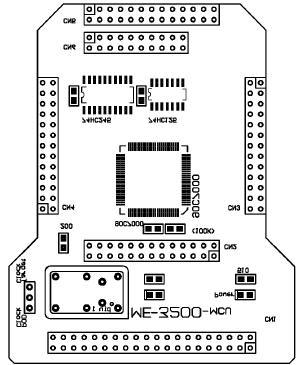
2 NOTES: 1. PSD834F2(8K RAM) is standard configuration, following optional parts may be purchased through your local distributors: PSD834F2V(8K RAM,3.3V) PSD854F2(32K RAM,5V) PSD854F2V(32K RAM,3.3V) 2. JTAG programmer upsd LINK is optional, it has following features: 6 or 4 wires JTAG programming 2.7V~5.5V operation voltage Linked with PC via Printer Port Supports PSDsoft Express of ST PARTS OF ME-3200 EMULATOR ME-3200 EMULATOR consists of six parts. They are Emulator Probe Assembly, Emulator Host, Cable for connection between Emulator Probe Assembly and Emulator Host, Cable for connection between Emulator Host and PC, JTAG Programmer upsd LINK(optional) and a Power Adapter. Each part is described as follows: Emulator Probe Assembly The Probe Assembly consists of tree modules: 1. Probe of Devices (POD) Tree types of POD are provided, they are: a. POD ME-3200-ADP-52, used to emulate microcontrollers of TQFP 52 package. The user s system should supply a sockets matrix as illustrated in fig 1(inner). The size of matrix is mil and the space between pins is 50 mil(1.27mm). b. POD ME-3200-ADP-80, used to emulate microcontrollers of TQFP 80 package. The user s system should supply a sockets matrix as illustrated in fig 1(outer). The size of the matrix is mil and the space between pins is 50 mil(1.27mm). c. POD ME-3200-ADP-DK3200, used in ST DK3200 DDK. It s pins matrix is consistent with sockets matrix on the ST DK3200 DDK. 2. PSD module ME-3200-PSD (fig 2) PSD module of Emulator Probe Assembly is used to emulate built in PSD circuits of upsd3200 family microcontrollers. 3. MCU module ME-3200-MCU (fig 3) MCU module is a base of Emulator Probe Assembly. The socket of 40 pins on it is for connection with ME-3200 Emulator Host. The selection of clock source for External Clock mode is also on MCU module. 2
3 Emulator Host ME-3200 Cable of Emulator Probe Assembly FLT40B-4 The four inches long cable which connects Emulator Probe Assembly and Emulator Host ensures reliable communication up to 33MHz system clock. Cable of Emulator Host CAB25DB This 25 wires cable is for high speed communication either between Emulator Host and PC or between JTAG Programmer upsd LINK and PC. JTAG Programmer upsd LINK (optional) It is optional and used to program all memory blocks(primary and secondary Flash memory), PLD logic, and PSD MODULE Configuration Register Bits of ST upsd3200 family of microcontrollers through JITAG interface. Power Adapter MS-100-AC220-DC9V/850mA This module Supplys 9V DC power for Emulator Host and Emulator Probe Assembly. It also powers upsd LINK when programming the device through JITAG interface. pig1. Adaptor 3
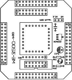
4 fig2. ME-3200-PSD fig3. ME-3200-MCU 4
5 DETERMINING EXTERNAL CLOCK ME-3200 EMULATOR has three choices for system clock, they are internal 12MHz, internal 24MHz and external oscillator, When external mode is chosen, the determining of clock source is made on the MCU module(me-3200-mcu). As illustrated in fig 3, there is a jumper on the up-left of MCU module, to make selection as follows: When the jumper is put on the position POD Clock, the clock is created on MCU module. There are tow ways to create clock: 1. Plug a two legs crystal of suitable frequency into the small oscillator PCB on MCU module. The system clock is created by this two legs crystal. 2. Take off the small oscillator PCB carefully and replace it with a four legs active crystal module. Pay attention to the pin mark on MCU module to avoid misplugging. In this case the clock comes from four legs active crystal. When the jumper is put on the position Target Clock, the clock source on user s system is chosen as system clock. The user must provide a stable clock out. VOLTAGE SELECTION OF PSD MODULE There is a jumper for voltage selection on PSD module (ME-3200-PSD). If PSD chip is PSD8x4F, put the jumper to position 5V. If PSD chip is PSD8x4FV, put the jumper to position 3.3V. CONNECTION OF ME-3200 EMULATOR After choosing right POD according to user s application, the parts connection of ME-3200 Emulator can be made as follows: Put PSD module ME-3200-PSD onto MCU module ME-3200-MCU in a piggyback way. Align plug pins and sockets on two modules and make they join together tightly. Put the chosen POD module under the MCU module ME-3200-MCU in a piggyback way. Align plug pins and sockets on two modules and make they join together tightly. Connect the Base, MCU module ME-3200-MCU, and Emulator Host with 40 wires flat cable (FLT40B-4). Plug one end of 25 wires cable (CAB25DB) into Printer Port of PC and fasten it by two fitting screws on the plug. If to program PSD, connect JITAG Programmer upsd LINK and PSD module(me-3200-psd) with 14 wires flat cable supplied with upsd LINK. Then plug another end of 25 wires cable (CAB25DB) into DB25 socket of upsd LINK. If to emulate 8052, disconnecte all connection of upsd LINK, and plug another end of 25 wires cable (CAB25DB) into DB25 socket of Emulator Host. Plug Power Adapter (MS-100-AC220-DC9V/850mA) to the socket of city power, then insert 9V DC out plug of Adapter into DC jack of Emulator Host. 5
6 USING ME-3200 EMULATOR There are tow phases during the development of ST upsd3200 family of microcontroller. Trey are designing and programming PSD module of upsd3200 and emulating 8052 microcontroller within upsd3200. Before start the second phase, the user must complete the first phase successfully. The procedures of phase 1 to program PSD module are shown as follows: 1. Set the voltage selection jumper on PSD module correctly according to user s application. 2. Connect upsd LINK to Printer Port of PC using 25 wires cable (CAB25DB). 3. Connect JTAG Port of upsd LINK to the same port on PSD module of Emulator Probe Assembly using 14 wires cable supplied with upsd LINK. 4. Plug Power Adapter into the socket of city power, then insert 9V DC out plug of Adapter into DC jack of Emulator Host. Emulator Host is also responsible to power Emulator Probe Assembly and JTAG Programmer upsd LINK. 5. Design and program PSD chip on ME_3200-PSD module using PSDsoft which is a Windows-based software development tool. The design for PSD module can be quickly and easily produced in a point and click environment NOTE: User only need to design and program PLD logic (DPLD and CPLD) and PSD MODULE Configuration Register Bits, and leave Flash Memory unprogrammed(primary and secondary Flash memory) blanked. Because during the emulating all user s codes in Flash Memory are mapped to Emulating RAM of Emulator Host. The phase 2 of to emulate 8052 in-circuit is described as follows: 1. Remove 9V DC plug from Emulator Host and disconnect all the connection of the upsd LINK. 2. Connect Emulator Host with PC using the 25 wires cable(cab25db). 3. Power Emulator Host again. 4. Run MedWin Integrated Development Environment and open dialog box of option Emulator, set the right parameters of ME Emulate the application program until the all program lines are executed successfully. NOTE: If PSD design has to be modified during the phase 2, the procedures of phase 1 must be repeated. 6

7 SETING ME-3200 EMULATOR UUDER MedWin Before to emulate the 8052 application program under MedWin, the parameters for ME-3200 Emulator must be set first. Choose Emulator command from options menu, a Emulator dialog box of two pages is popped out. The first page displayed is Emulator Setting, shown as follows: The user should choose right parameters according to his application. NOTES: 1. When choose option external of the title oscillator, the oscillator to be used is determined by the hardware setting on MCU module of Emulator Probe Assembly. 2. The ALE output of the 8052 can be set as constant high level or continuous pulse. The latter is useful to users who use ALE as a clock. The second page of Emulator dialog box is PSD Setting, shown as follows: 7

8 NOTES: 1. The value of CSIOP should be same as the value when PSD module hardware is designed, otherwise ME-3200 Emulator will not be able to access I/O ports and SRAM of PSD module within upsd3200. The default is 02H when emulators leave factory. 2. Set the value of PSel0 and PSel1 according to user s hardware design. 3. The size of internal SRAM of PSD must be consistent with device to be emulated. For example, choose 8K SRAM for PSD834 and 32K SRAM for PSD854. The address range should be same as that when PSD module hardware is designed. 4. In ME-3200 Emulator, Bit0 to bit4 of Page Register are used as page selection while bit7 and bit6 are used as control of Internal/External memory selection. 5. Configuration file 8
EB-51 Low-Cost Emulator
 EB-51 Low-Cost Emulator Development Tool for 80C51 Microcontrollers FEATURES Emulates 80C51 Microcontrollers and Derivatives Real-Time Operation up to 40 MHz 3.3V or 5V Voltage Operation Source-Level Debugger
CEIBO FE-51RD2 Development System
 CEIBO FE-51RD2 Development System Development System for Atmel AT89C51RD2 Microcontrollers FEATURES Emulates Atmel AT89C51RD2 60K Code Memory Real-Time Emulation Frequency up to 40MHz / 3V, 5V ISP and
CEIBO FE-5111 Development System
 CEIBO FE-5111 Development System Development System for Atmel W&M T89C5111 Microcontrollers FEATURES Emulates Atmel W&M T89C5111 4K Code Memory Real-Time Emulation and Trace Frequency up to 33MHz/5V ISP
CEIBO FE-W7 Development System
 CEIBO FE-W7 Development System Development System for Winbond W7xxxx Microcontrollers FEATURES Emulates Winbond W77xxx or W78xxx Microcontrollers 125K Code Memory Real-Time Emulation Frequency up to fmax
CEIBO FE-5131A Development System
 CEIBO FE-5131A Development System Development System for Atmel AT89C5131A Microcontrollers FEATURES Emulates AT89C5131/AT89C5131A with 6/12 Clocks/Cycle 31K Code Memory Software Trace Real-Time Emulation
Quick Start Guide for the Turbo upsd DK3300-ELCD Development Kit- RIDE
 Contents: Circuit Board upsd DK3300-ELCD Development Board with a upsd3334d-40u6 MCU with Enhanced Graphic LCD RLINK-ST, a USB-based JTAG adapter from Raisonance for debugging with Raisonance Integrate
Programming in the MAXQ environment
 AVAILABLE The in-circuit debugging and program-loading features of the MAXQ2000 microcontroller combine with IAR s Embedded Workbench development environment to provide C or assembly-level application
CPLD/FPGA Development System
 Chapter 1 CPLD/FPGA Development System As shown in Figure 1-1, CPLD (Complex Programmable Logic Device) and FPGA (Field-Programmable Gate Array) are the programmable logic devices (PLDs) whose internal
_ V1.3. MPC564xB ActiveGT POD. POD Hardware Reference
 _ V1.3 POD Hardware Reference MPC564xB ActiveGT POD Ordering code IC30762 Thank you for purchasing this product from isystem. This product has been carefully crafted to satisfy your needs. Should any questions
ST SPC58 B Line Emulation Adapter System
 _ V1.1 Hardware Reference ST SPC58 B Line Emulation Adapter ST SPC58 B Line Emulation Adapter System ST SPC58 B line emulation adapter primary use case is providing Nexus trace functionality for the SPC58
CPLD board datasheet EB
 CPLD board datasheet EB020-00-3 Contents. About this document... 2 2. General information... 3 3. Board layout... 4 4. Testing this product... 5 5. Circuit description... 6 Appendix Circuit diagram Copyright
FR30-RAM-Stack-Board Documentation Part-Number: FR-RAM-STACK1-100P-M06
 FR30-RAM-Stack-Board Documentation Part-Number: FR-RAM-STACK1-100P-M06 Fujitsu Mikroelektronik GmbH Am Siebenstein 6-10 63303 Dreieich-Buchschlag, Germany Revision: Date: 1.1 30/7/99 Page 1 Contents Hardware
IN-CIRCUIT DEBUG (ICD) USER GUIDE
 USER GUIDE") April 2003 IN-CIRCUIT DEBUG (ICD) USER GUIDE The Western Design Center, Inc., 2002 WDC TABLE OF CONTENTS 1. Introduction...3 2. Debug Port...4 3. The ICD Registers...4 4. ICDCTRL Register Bit Definitions...5
April 2003 IN-CIRCUIT DEBUG (ICD) USER GUIDE The Western Design Center, Inc., 2002 WDC TABLE OF CONTENTS 1. Introduction...3 2. Debug Port...4 3. The ICD Registers...4 4. ICDCTRL Register Bit Definitions...5
TEMIC 51T (Temic) EMULATION
 EMULATION") Note: To use with frequencies above 40Mhz it will be required to use an emulator board that has been specially modified to obtain high frequency operation and will work only with the POD-51Temic. The EPROM
Note: To use with frequencies above 40Mhz it will be required to use an emulator board that has been specially modified to obtain high frequency operation and will work only with the POD-51Temic. The EPROM
Nohau Supports the ST Microelectronics upsd3200 Architecture
 What this document is and about pricing Nohau Supports the ST Microelectronics upsd3200 Architecture What an emulator is and what it does Introduction EMUL51-PC for the ST upsd3200 Parts List This price
POD 51EH C541U 12 EA ALE PSEN XH0 XH1 XH2 XH3 XH4 XH5 XH6 XH7 XL7 XL6 XL5 XL4 XL3 XL2 XL1 XL0. Figure 1. POD 51EH C541U 12
 6 7.. P P POD 5EH C54U RST R PWD Y IDL Y EML G MON Y MERR R JP JP T JP7 ANB FLF EMUL XH0 XH XH XH XH4 XH5 XH6 XH7 EA ALE PSEN T XS MCU XS T 7 6 5 4 0 D P P P D M JP0 XL7 XL6 XL5 XL4 XL XL XL XL0 FULL USL
DS-XA In-Circuit Emulator
 DS-XA In-Circuit Emulator In-Circuit Emulator for Philips XA Microcontrollers FEATURES Emulates XA Derivatives 2MByte Code and Data Memory Memory With Mapping Capabilities Real-Time Trace Frequency Range
_ V1.3. Motorola 68HC11 AE/AS POD rev. F. POD Hardware Reference
 _ V1.3 POD Hardware Reference Motorola 68HC11 AE/AS POD rev. F Ordering code IC81049 Thank you for purchasing this product from isystem. This product has been carefully crafted to satisfy your needs. Should
DS-251 In-Circuit Emulator
 DS-251 In-Circuit Emulator In-Circuit Emulator for 251 Microcontrollers FEATURES Real-Time and Transparent In-Circuit Emulator for 251s Standard 256K Emulation Memory Real-Time Trace up to 128K Frames
This catalog includes the description and specifications for all Ceibo Development Tools. Systems are grouped in seven categories:
 INTRODUCTION Development Tool for 80C51 Microcontrollers This catalog includes the description and specifications for all Ceibo Development Tools. Systems are grouped in seven categories: Development Boards:
EMUL51XA PC. User Guide. Edition 1. ICE Technology - All rights reserved worldwide.
 EMUL51XA PC User Guide Edition 1 ICE Technology - All rights reserved worldwide. EMUL51XA PC User Guide Contents About this Guide vii Downloading EMUL51XA PC Product Documentation vii Overview of the EMUL51XA
Programmable Peripheral Application Note 048
 Programmable Peripheral Application Note 048 Designing with Flash Memory By Dan Friedman WSI Introduction Flash Memory has gained a wide popularity as a choice of use in embedded system solutions. Many
CPLD board datasheet EB
 CPLD board datasheet EB020-00- Contents. About this document... 2 2. General information... 3 3. Board layout... 4 4. Testing this product... 5 5. Circuit description... 6 Appendix Circuit diagram Copyright
Goal: We want to build an autonomous vehicle (robot)
") Goal: We want to build an autonomous vehicle (robot) This means it will have to think for itself, its going to need a brain Our robot s brain will be a tiny computer called a microcontroller Specifically
Goal: We want to build an autonomous vehicle (robot) This means it will have to think for itself, its going to need a brain Our robot s brain will be a tiny computer called a microcontroller Specifically
POD 51EH C517A 24 XH0 XH1 XH2 XH3 XH4 XH5 XH6 XH7 XL7 XL6 XL5 XL4 XL3 XL2 XL1 XL0 PE EA ALE PSEN JP1. Figure 1. POD 51EH C517A 24
 6 7.. P P POD 5EH C57A 4 RST R PWD Y IDL Y EML G MON Y MERR R JP T JP7 ANB FLF EMUL XH0 XH XH XH XH4 XH5 XH6 XH7 T XS MCU XS T 7 6 5 4 0 P P P6 P7 JP0 XL7 XL6 XL5 XL4 XL XL XL XL0 PE EA ALE PSEN JP P5
Freescale and the Freescale logo are trademarks of Freescale Semiconductor, Inc. All other product or service names are the property of their
 S08 Highlighted Features Why Do I Need a Slave LIN Interface Controller (SLIC)? Design Challenges Slave synchronization Slave synchronizing to LIN messaging requires a cost versus resource trade-off. Your
CMS-8GP32. A Motorola MC68HC908GP32 Microcontroller Board. xiom anufacturing
 CMS-8GP32 A Motorola MC68HC908GP32 Microcontroller Board xiom anufacturing 2000 717 Lingco Dr., Suite 209 Richardson, TX 75081 (972) 994-9676 FAX (972) 994-9170 email: Gary@axman.com web: http://www.axman.com
EMULATOR SYSTEM MB
 Fujitsu Microelectronics Europe Application Note MCU-AN-391026-E-V12 FR FAMILY SUPPORT TOOL EMULATOR SYSTEM MB2198-01 INSTALLATION GUIDE MB2198-01 APPLICATION NOTE Revision History Revision History Date
CEIBO FE-5122 Development System
 CEIBO FE-5122 Development System Development System for Atmel AT8xC5122 Microcontrollers FEATURES Emulates AT8xC5122 Derivatives with 6/12 Clocks/Cycle 32K Code Memory Software Trace Real-Time Emulation
All information, including contact information, is available on our web site Feel free also to explore our alternative products.
 _ V1.1 POD Hardware Reference Intel 80186 EA POD POD rev. D Ordering code IC20011-1 Thank you for purchasing this product from isystem. This product has been carefully crafted to satisfy your needs. Should
USB Debug Adapter. Power USB DEBUG ADAPTER. Silicon Laboratories. Stop. Run. Figure 1. Hardware Setup using a USB Debug Adapter
 C8051F2XX DEVELOPMENT KIT USER S GUIDE 1. Kit Contents The C8051F2xx Development Kits contain the following items: C8051F206 or C8051F226 Target Board C8051Fxxx Development Kit Quick-Start Guide Silicon
ARM programmer and daughter board EB Technical datasheet
 ARM programmer and daughter board EB185-00-1 Technical datasheet Contents 1 About this document...2 2 General information...3 3 Description...3 4 Board layout...4 5 Testing this product...5 6 Circuit description...7
DS-51 Development System
 DS-51 Development System User's Manual COPYRIGHT BY CEIBO Rev. 05/14 - V1.1 POWER UP SEQUENCE Vcc from the emulator is disconnected in the emulator plug. For example, Pin 40 for the DIP package is disconnected
ARDUINO LEONARDO WITH HEADERS Code: A000057
 ARDUINO LEONARDO WITH HEADERS Code: A000057 Similar to an Arduino UNO, can be recognized by computer as a mouse or keyboard. The Arduino Leonardo is a microcontroller board based on the ATmega32u4 (datasheet).
S3 Flash In-System Programmer
 S3 Family of Microcontrollers S3 Flash In-System Programmer UM026604-0816 PRELIMINARY Copyright 2016 Zilog, Inc. All rights reserved. www.zilog.com ii Warning: DO NOT USE THIS PRODUCT IN LIFE SUPPORT SYSTEMS.
POD 51EH C505L XH0 XH1 XH2 XH3 XH4 XH5 XH6 XH7 XL7 XL6 XL5 XL4 XL3 XL2 XL1 XL0. Figure 1. POD 51EH C505L 20
 6 7.. P P POD 5EH C505L 0 RST R PWD Y IDL Y EML G MON Y MERR R JP T JP0 JP7 ANB FLF EMUL XH0 XH XH XH XH4 XH5 XH6 XH7 XL7 XL6 XL5 XL4 XL XL XL XL0 T XS GSL T MCU RSL T XS T P P4 5 4 0 7 6 5 4 0 NOHAU Corporation
ARDUINO MEGA 2560 REV3 Code: A000067
 ARDUINO MEGA 2560 REV3 Code: A000067 The MEGA 2560 is designed for more complex projects. With 54 digital I/O pins, 16 analog inputs and a larger space for your sketch it is the recommended board for 3D
SRAM SRAM SRAM. Data Bus EXTAL ESSI KHz MHz. In Headphone CS MHz. Figure 1 DSP56302EVM Functional Block Diagram
 MOTOROLA SEMICONDUCTOR PRODUCT INFORMATION Advance Information Evaluation Module Order this document by: P/D The Evaluation Module () is designed as a low-cost platform for developing real-time software
ARDUINO MEGA INTRODUCTION
 ARDUINO MEGA INTRODUCTION The Arduino MEGA 2560 is designed for projects that require more I/O llines, more sketch memory and more RAM. With 54 digital I/O pins, 16 analog inputs so it is suitable for
eip-24/100 Embedded TCP/IP 10/100-BaseT Network Module Features Description Applications
 Embedded TCP/IP 10/100-BaseT Network Module Features 16-bit Microcontroller with Enhanced Flash program memory and static RAM data memory On board 10/100Mbps Ethernet controller, and RJ45 jack for network
Table of Contents TABLE OF CONTENTS...1
 Table of Contents TABLE OF CONTENTS...1 STK504 UR GUIDE...2 Introduction... 2 Features...2 Known Issues... 4 Getting Started... 5 Hardware overview...5 Mounting the STK504...6 Placing the AVR in the ZIF
DS-51 Microprocessor Development System
 DS-51 Microprocessor Development System In-Circuit Emulator for 8051 Family of Microcontrollers FEATURES Real-Time and Transparent In-Circuit Emulator Supports Most of the 8051 Derivatives Emulates 1.5V
1. Attempt any three of the following: 15
 (2½ hours) Total Marks: 75 N. B.: (1) All questions are compulsory. (2) Make suitable assumptions wherever necessary and state the assumptions made. (3) Answers to the same question must be written together.
M68EM05X4 EMULATOR MODULE USER'S MANUAL
 M68EM05X4/D Rev. 2 January 1996 M68EM05X4 EMULATOR MODULE USER'S MANUAL Third Edition MOTOROLA Ltd., 1993, 1995, 1996; All Rights Reserved Motorola reserves the right to make changes without further notice
Evaluation & Development Kit for Freescale PowerPC MPC5517 Microcontroller
 _ V1.0 User s Manual Evaluation & Development Kit for Freescale PowerPC MPC5517 Microcontroller Ordering code ITMPC5517 Copyright 2007 isystem AG. All rights reserved. winidea is a trademark of isystem
Bolero Nexus Emulation Adapter 208BGA 100TQ
 _ V1.5 Adapters Bolero Nexus Emulation Adapter 208BGA 100TQ Ordering code IA208BGA100TQ-5607B Supported microcontrollers: Freescale MPC5605B, MPC5605BK, MPC5606BK ST equivalent devices (SPC560B54, SPC560B60)
ARDUINO M0 PRO Code: A000111
 ARDUINO M0 PRO Code: A000111 The Arduino M0 Pro is an Arduino M0 with a step by step debugger With the new Arduino M0 Pro board, the more creative individual will have the potential to create one s most
Description of the Simulator
 Description of the Simulator The simulator includes a small sub-set of the full instruction set normally found with this style of processor. It includes advanced instructions such as CALL, RET, INT and
Assembly Guide. LEDs. With these assembly instructions, you can easily build your own SWT16. All required components are included in this kit.
 Assembly Guide With these assembly instructions, you can easily build your own SWT16. All required components are included in this kit. You need the following tools: soldering iron, wire cutter and solder.
ECE3120: Computer Systems Hardware & Software Development Tools
 ECE3120: Computer Systems Hardware & Software Development Tools Manjeera Jeedigunta http://blogs.cae.tntech.edu/msjeedigun21 Email: msjeedigun21@tntech.edu Tel: 931-372-6181, Prescott Hall 120 The HCS12
F2MC MB90385 series Evaluation Board Documentation. Revision Date Comment V New document
 F2MC MB90385 series Evaluation Board Documentation Revision Date Comment V1.0 08.25.02 New document 1 Warranty and Disclaimer To the maximum extent permitted by applicable law, Fujitsu Microelectronics
Embedded World Television, Radio, CD player, Washing Machine Microwave Oven Card readers, Palm devices
 A presentation on INTRODUCTION We are living in the Embedded World. We are surrounded with many embedded products and our daily life largely depends on the proper functioning of these gadgets. Television,
ARDUINO YÚN Code: A000008
 ARDUINO YÚN Code: A000008 Arduino YÚN is the perfect board to use when designing connected devices and, more in general, Internet of Things projects. It combines the power of Linux with the ease of use
_ V Intel 8085 Family In-Circuit Emulation. Contents. Technical Notes
 _ V9.12. 225 Technical Notes Intel 8085 Family In-Circuit Emulation This document is intended to be used together with the CPU reference manual provided by the silicon vendor. This document assumes knowledge
Bolero3M Nexus Emulation Adapter 256BGA 176TQ
 _ V1.4 Adapters Bolero3M Nexus Emulation Adapter 256BGA 176TQ Ordering code IA256BGA176TQ-5646C Supported microcontrollers: Freescale MPC5644B, MPC5644C, MPC5645B, MPC5645C, MPC5646B and MPC5646C ST equivalent
BIG8051. Development system. User manual
 BIG8051 User manual All s development systems represent irreplaceable tools for programming and developing microcontroller-based devices. Carefully chosen components and the use of machines of the last
ARM programmer and daughter board
 ARM programmer and daughter board www.matrixtsl.com EB185 Contents About this document 3 Board layout 3 General information 4 Circuit description 4 Protective cover 5 Circuit diagram 6 2 Copyright About
ATmega128. Introduction
 ATmega128 Introduction AVR Microcontroller 8-bit microcontroller released in 1997 by Atmel which was founded in 1984. The AVR architecture was conceived by two students (Alf-Egil Bogen, Vergard-Wollen)
UNIVERSITY OF HONG KONG DEPARTMENT OF ELECTRICAL AND ELECTRONIC ENGINEERING
 UNIVERSITY OF HONG KONG DEPARTMENT OF ELECTRICAL AND ELECTRONIC ENGINEERING Experiment PCO: Principles of Computer Operation Location: Part I Lab., CYC 102. Objective: The objective is to learn the basic
USB Debug Adapter. Power USB DEBUG ADAPTER. Silicon Laboratories. Stop. Run. Figure 1. Hardware Setup using a USB Debug Adapter
 C8051F38X DEVELOPMENT KIT USER S GUIDE 1. Kit Contents The C8051F38x Development Kit contains the following items: C8051F380 Target Board C8051Fxxx Development Kit Quick-start Guide Silicon Laboratories
ARDUINO MINI 05 Code: A000087
 ARDUINO MINI 05 Code: A000087 The Arduino Mini is a very compact version of the Arduino Nano without an on board USB to Serial connection The Arduino Mini 05 is a small microcontroller board originally
XC164CS Prototype Board
 XC164CS Prototype Board Features: Small PCB (95 x 57 mm) with ground plane. o Designed to fit inside a Pac Tec FLX-4624 ABS enclosure Infineon XC164CS 16-bit single-chip microcontroller o 166SV2 core o
SRAM SRAM SRAM SCLK khz
 MOTOROLA nc. SEMICONDUCTOR PRODUCT INFORMATION Advance Information Evaluation Module Order this document by: P/D The DSP56603 Evaluation Module () is designed as a low-cost platform for developing real-time
Renesas 78K/78K0R/RL78 Family In-Circuit Emulation
 _ Technical Notes V9.12.225 Renesas 78K/78K0R/RL78 Family In-Circuit Emulation This document is intended to be used together with the CPU reference manual provided by the silicon vendor. This document
CNC Shield Guide V
 CNC Shield Guide V1.0 12 2018 Maker Group Global LLC 2018 Safety Statement The author of this document is not liable or responsible for any accidents, injuries, equipment damage, property damage, loss
SBAT90USB162 Atmel. SBAT90USB162 Development Board User s Manual
 SBAT90USB162 Atmel AT90USB162 Development Board User s manual 1 1. INTRODUCTION Thank you for choosing the SBAT90USB162 Atmel AT90USB162 development board. This board is designed to give a quick and cost-effective
Getting Started Guide RS-EDP & XC167 CPU Module. Version 2 10th June 2010
 Getting Started Guide RS-EDP & XC167 CPU Module Version 2 10th June 2010 Electrocomponents plc Page 1 Contents 1. Introduction 3 2. Development Tool Support 4 2.1 FTDI Based USB to JTAG Converter... 4
Sierra Radio Systems. Digital Compass. Reference Manual. Version 1.0
 Sierra Radio Systems Digital Compass Reference Manual Version 1.0 Contents Digital compass board RS485 power injector For more information, go to the Sierra Radio Systems web site at www.sierraradio.net
indart -HCS08 In-Circuit Debugger/Programmer for Freescale HCS08 Family FLASH Devices User s Manual Rev. 2.0
 indart -HCS08 In-Circuit Debugger/Programmer for Freescale HCS08 Family FLASH Devices User s Manual Rev. 2.0 Copyright 2006 SofTec Microsystems DC01028 We want your feedback! SofTec Microsystems is always
SECURE DIGITAL ACCESS SYSTEM USING IBUTTON
 SECURE DIGITAL ACCESS SYSTEM USING IBUTTON Access control forms a vital link in a security chain. Here we describe a secure digital access system using ibutton that allows only authorised persons to access
F²MC-8FX FAMILY MB95100 SERIES EMULATOR HW SETUP 8-BIT MICROCONTROLLER APPLICATION NOTE. Fujitsu Microelectronics Europe Application Note
 Fujitsu Microelectronics Europe Application Note MCU-AN-395002-E-V10 F²MC-8FX FAMILY 8-BIT MICROCONTROLLER MB95100 SERIES EMULATOR HW SETUP APPLICATION NOTE Revision History Revision History Date 2004-10-12
STK521. User Guide B AVR 01/12
 STK521... User Guide Table of Contents Section 1 1 Introduction 1 Features 2 Section 2 3 Using the STK521 Top Module 3 Connecting the Atmel STK521 to the Atmel STK500 Starter Kit 3 Powering the STK521
EasyAVR6 Development System
 EasyAVR6 Development System Part No.: MPMICRO-AVR-Devel-EasyAVR6 Overview EasyAVR6 is a development system that supports a wide range of 8-, 14-, 20-, 28- and 40-pin AVR MCUs. EasyAVR6 allows AVR microcontrollers
AC/DC Adapter. Figure 1. Hardware Setup
 C8051F12X DEVELOPMENT KIT USER S GUIDE 1. Kit Contents The C8051F12x Development Kit contains the following items: C8051F120 Target Board Serial Adapter (RS232 to Target Board Debug Interface Protocol
KPIC-0818P (V050919) Devices Included in this Data sheet: KPIC-0818P
 Devices Included in this Data sheet: KPIC-0818P") Devices Included in this Data sheet: KPIC-0818P Features: Carefully designed prototyping area Accepts 8 pin PIC12 series micro-controllers Accepts 14 and 18 Pin PIC16 series Accepts some 8,14 and 18 pin
Devices Included in this Data sheet: KPIC-0818P Features: Carefully designed prototyping area Accepts 8 pin PIC12 series micro-controllers Accepts 14 and 18 Pin PIC16 series Accepts some 8,14 and 18 pin
CC186 AND CC186/2 STAND-ALONE OR SYSTEM CLOCK
 FN:CC186M2.DOC CC186 AND CC186/2 STAND-ALONE OR SYSTEM CLOCK DESCRIPTION The CC186 is a single sided clock with six, 1.8 inch high digits. The CC186/2 is a double sided clock with six, 1.8 inch high digits
Adapter guide for C167/ST10, emulators
 Adapter guide for C167/ST10, emulators As microcontrollers are getting more complex, and more pins are added, package land patterns are getting finer. This can present a problem when trying to attach an
Table Of Contents TABLE OF CONTENTS...1
 Table Of Contents TABLE OF CONTENTS...1 STK503 USER GUIDE...2 INTRODUCTION...2 Features...2 Known Issues...3 Getting Started...4 Hardware overview...4 Mounting the STK503...5 Placing the AVR in the ZIF
AN231K04-DVLP3 AnadigmApex Development Board
 1.0 Overview The AnadigmApex development board is an easy-to-use platform designed to help you get started with implementing and testing your analog designs on the AnadigmApex FPAA silicon devices. While
Locktronics PICmicro getting started guide
 Page 2 getting started guide What you need to follow this course 2 Using the built-in programs 3 Create your own programs 4 Using Flowcode - your first program 5 A second program 7 A third program 8 Other
Section 1 Introduction
 Section 1 Introduction The AT90ICEPRO is a real time In-Circuit Emulator (ICE) for all AT90S1200, -S2313, -S2323, -S2333, -S2343, -S4414, -S4433, -S4434, -S8515 and -S8535 devices. It can be upgraded to
CPLD board. EB020
 CPLD board www.matrixtsl.com EB020 Contents About this document Board layout General information Circuit description Protective cover Circuit diagram 2 4 5 7 Copyright About this document This document
UNIVERSITY OF HONG KONG DEPARTMENT OF ELECTRICAL AND ELECTRONIC ENGINEERING. Principles of Computer Operation
 UNIVERSITY OF HONG KONG DEPARTMENT OF ELECTRICAL AND ELECTRONIC ENGINEERING Experiment PCO: Principles of Computer Operation Location: Part I Lab., CYC 102. Objective: The objective is to learn the basic
Phase Loss Protection Upgrade. Phase Loss Protection Upgrade. In this bulletin:
 Phase Loss Protection Upgrade In this bulletin: Introduction... 2 Purpose... 2 General... 2 Applicability... 2 HD3070 Phase Loss Protection Upgrade Kit Parts... 2 Preparation... 4 Install the Phase Loss
About the Presentations
 About the Presentations The presentations cover the objectives found in the opening of each chapter. All chapter objectives are listed in the beginning of each presentation. You may customize the presentations
Mega128-DEVelopment Board Progressive Resources LLC 4105 Vincennes Road Indianapolis, IN (317) (317) FAX
 (317) FAX") Mega128-DEVelopment Board Progressive Resources LLC 4105 Vincennes Road Indianapolis, IN 46268 (317) 471-1577 (317) 471-1580 FAX http://www.prllc.com GENERAL The Mega128-Development board is designed for
Mega128-DEVelopment Board Progressive Resources LLC 4105 Vincennes Road Indianapolis, IN 46268 (317) 471-1577 (317) 471-1580 FAX http://www.prllc.com GENERAL The Mega128-Development board is designed for
Revision: May 11, E Main Suite D Pullman, WA (509) Voice and Fax LED. Doc: page 1 of 6
 Voice and Fax LED. Doc: page 1 of 6") Digilent XC2-XL System Board Reference Manual www.digilentinc.com Revision: May 11, 2004 215 E Main Suite D Pullman, WA 99163 (509) 334 6306 Voice and Fax Overview The Digilent XC2-XL System Board (the
Digilent XC2-XL System Board Reference Manual www.digilentinc.com Revision: May 11, 2004 215 E Main Suite D Pullman, WA 99163 (509) 334 6306 Voice and Fax Overview The Digilent XC2-XL System Board (the
M16C/62 APPLICATION NOTE. Programming the M16C/62 in Flash Parallel Mode. 1.0 Abstract. 2.0 Introduction. 3.0 Setting Up the PGM1000 Programmer
 APPLICATION NOTE M16C/62 1.0 Abstract The following article describes using the ATC (Advanced Transdata) PGM1000 programmer to parallel program the flash memory of the M16C/62 series of microcontrollers.
EVALKITSTKNX. Miniature transceiver STKNX evaluation and development kit. Features
 Miniature transceiver STKNX evaluation and development kit Data brief Features Full KNX twisted pair device development kit based on the STKNX miniature transceiver Controlled by STM32F103 microcontroller
Approximately half the power consumption of earlier Renesas Technology products and multiple functions in a 14-pin package
 Renesas Technology to Release R8C/Mx Series of Flash MCUs with Power Consumption Among the Lowest in the Industry and Powerful On-Chip Peripheral Functions Approximately half the power consumption of earlier
ARDUINO MEGA ADK REV3 Code: A000069
 ARDUINO MEGA ADK REV3 Code: A000069 OVERVIEW The Arduino MEGA ADK is a microcontroller board based on the ATmega2560. It has a USB host interface to connect with Android based phones, based on the MAX3421e
keyestudio Keyestudio MEGA 2560 R3 Board
 Keyestudio MEGA 2560 R3 Board Introduction: Keyestudio Mega 2560 R3 is a microcontroller board based on the ATMEGA2560-16AU, fully compatible with ARDUINO MEGA 2560 REV3. It has 54 digital input/output
Shack Clock kit. U3S Rev 2 PCB 1. Introduction
 Shack Clock kit U3S Rev 2 PCB 1. Introduction Thank you for purchasing the QRP Labs Shack Clock kit. This clock uses the Ultimate3S QRSS/WSPR kit hardware, but a different firmware version. It can be used
Keywords Digital IC tester, Microcontroller AT89S52
 Volume 6, Issue 1, January 2016 ISSN: 2277 128X International Journal of Advanced Research in Computer Science and Software Engineering Research Paper Available online at: www.ijarcsse.com Digital Integrated
SK18A. 18 Pins PIC START-UP KIT. User s Manual V1.1. Dec 2007
 SK18A 18 Pins PIC START-UP KIT User s Manual V1.1 Dec 2007 Information contained in this publication regarding device applications and the like is intended through suggestion only and may be superseded
AN231K04-DVLP3 AnadigmApex Development Board
 1.0 Overview The AnadigmApex development board is an easy-to-use platform designed to help you get started with implementing and testing your analog designs on the AnadigmApex FPAA silicon devices. While
EasyPIC5 Development System
 EasyPIC5 Development System Part No.: MPMICRO-PIC-Devel- EasyPIC5 Overview EasyPIC5 is a development system that supports over 120 8-, 14-, 18-, 20-, 28- and 40-pin PIC MCUs. EasyPIC5 allows PIC microcontrollers
AC/DC. Adapter. Serial. Adapter. Figure 1. Hardware Setup
 C8051F35X DEVELOPMENT KIT USER S GUIDE 1. Kit Contents The C8051F35x Development Kit contains the following items: C8051F350 Target Board Serial Adapter (RS232 to Target Board Debug Interface Protocol
Getting Started with STK200 Dragon
 Getting Started with STK200 Dragon Introduction This guide is designed to get you up and running with main software and hardware. As you work through it, there could be lots of details you do not understand,
1. About this document General information Board layout Testing this product Circuit description...
 dspic / PIC24 Multiprogrammer datasheet EB064-00 00-1 Contents 1. About this document... 2 2. General information... 3 3. Board layout... 4 4. Testing this product... 5 5. Circuit description... 6 Appendix