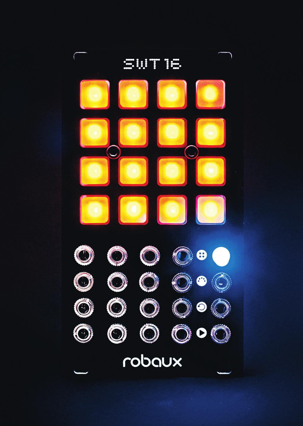
Assembly Guide. LEDs. With these assembly instructions, you can easily build your own SWT16. All required components are included in this kit.
|
|
|
- Collin Long
- 5 years ago
- Views:
Transcription
1
2


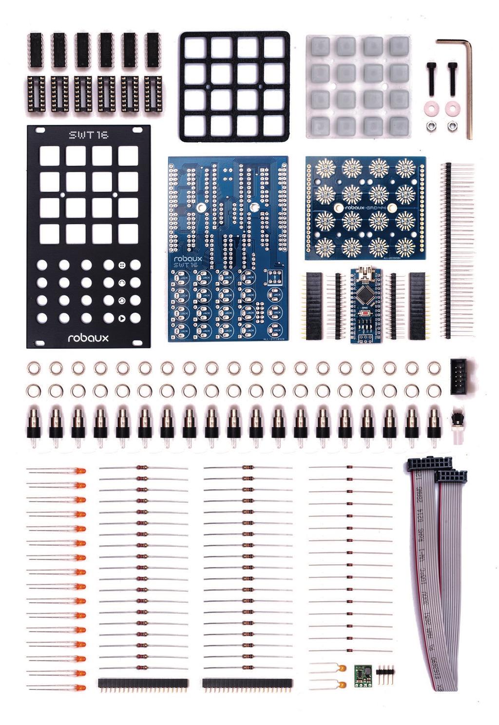
3 Assembly Guide With these assembly instructions, you can easily build your own SWT16. All required components are included in this kit. You need the following tools: soldering iron, wire cutter and solder. Also a desoldering pump and a nut driver. Read the instructions carefully and follow the steps in the correct order. Robaux wishes you much fun building the Sweet LEDs We start with the button board. Attach and solder the sixteen LEDs as shown in the picture. Please pay attention to the polarity of the LEDs. The long leg comes into the + hole, the short leg into the - hole.

4 2 20 Pin Header Next, solder the two 20-pin headers to the back of the button board. It is best to first solder the two outer pins and then the remaining pins. 3 4x4 Keypad Now place the 4x4 Button Keypad on the front of the Button Board. Make sure that the holes on the keypad match the holes on the button board.


5 4 Frame Now put the frame on the keypad. Make sure the holes in the frame match the holes in the keypad. 5 Frontpanel Now it s time to put the front panel on the buttons.


6 6 Screws Now fix the front panel, the frame, the keypad and the button board with the two screws. Insert the screws through all parts as shown in the picture. 7 Nuts Secure the screws with the washers and nuts.


7 8 Allen key Tighten the screws with the supplied allen key. Please do not over tighten the screws so that none of the parts will be damaged. 9 Resistor 220 Now pick up the motherboard and solder the nineteen 220 ohm resistors as shown in the picture. You can recognize the resistors by their color code Red, Red, Brown, Gold.
8 10 Resistor 10K Now solder the nineteen 10K resistors to the board. You can recognize the resistors by their color code Brown, Black, Orange, Gold. 11 Diodes Now solder the sixteen diodes to the board as shown in the picture. Please pay attention to the polarity.

9 12 Pins Now solder the 4 pins on the board. There, the step-down adapter will be soldered on later. If you like, you can shorten the pins to the height of the adapter before soldering them on. 13 Capacitor 104 Now solder the two 104 capacitors to the board as shown in the picture.

10 14 IC Socket Now solder the six IC sockets to the board. It is easiest to solder first only the outer pins and then the remaining ones Pin Header Next, solder the two 15-pin headers onto the main board. It is best to solder first the two outer pins and then the remaining pins.


11 16 Power Socket Now solder the power socket as shown in the picture. Notice that the socket points in the right direction. 17 Button Now plug the button on the front of the main board. Please do not solder the button yet! Notice that the white mark on the button matches the white mark on the PCB.


12 18 Jacks Now plug the nineteen jack sockets on the motherboard. Please do not solder them yet! If you like, you can trim the pins of the jacks to the same length. 19 Washer Place a washer on each jack. This ensures that the jacks have the correct distance to the front panel.


13 20 Knurled Nuts Now place the front panel with the buttons on the main board. Align all the jacks and fix them with the knurled nuts. 21 Long Pins Now comes the tricky part. Insert the long pins through the main board into the header of the button board. Align everything carefully and then solder the long pins to the main board.


14 22 Trim the pins Now trim the long pins as shown in the picture. Then resolder the pins. Then solder all jacks and the button on the main board. 23 Step Down Now solder the step-down adapter to the pins as shown in the picture. Make sure that the components on the adapter point upwards.


15 24 Arduino Now plug the Arduino board onto the headers as shown in the picture. Note that the USB connector should point upwards. 25 ICs Now insert the ICs into the sockets. Be sure to attach them in the correct direction as shown in the picture. Voilà - your SWT16 is ready!

16
TIME WIZARD MULTI CLOCK DIVIDER BUILDING GUIDE
 TIME WIZARD MULTI CLOCK DIVIDER BUILDING GUIDE Table of Contents 0. Components List + Tools 0. PCB Sides 03. PCB Assembly 04_. Diode N448 04_. Laying Resistors 04_3. Capacitors 04_4. Quartz 04_5. 78L05
MAIN PCB (The small one)
") THANKS FOR CHOOSING ONE OF OUR KITS! This manual has been written taking into account the common issues that we often find people experience in our workshops. The order in which the components are placed
THANKS FOR CHOOSING ONE OF OUR KITS! This manual has been written taking into account the common issues that we often find people experience in our workshops. The order in which the components are placed
Post Tenebras Lab. Written By: Post Tenebras Lab
 Post Tenebras Lab PTL-ino is an Arduino comptaible board, made entirely out of through-hole components. It is a perfect project to learn how to solder and start getting into the world of micro controllers.
BuffaloLabs WiFi Lantern Assembly guide version 1
 BuffaloLabs WiFi Lantern Assembly guide version 1 Needed equipment: Solder iron Solder wire Cutter Wire stripper (optional) Hot glue gun Overview of the components (not including USB cable and box panels)
UF-3701 Power Board Construction Guide
 Page 1/5 Soldering and Part Placement See the Chapter 3 of the MIT 6270 Manual for information on electronic assembly, including soldering techniques and component mounting. Construction Information All
SRI-02 Speech Recognition Interface
 SRI-02 Speech Recognition Interface Data & Construction Booklet The Speech Recognition Interface SRI-02 allows one to use the SR-07 Speech Recognition Circuit to create speech controlled electrical devices.
MAIN PCB (The small one with the square cut out from one side)
") THANKS FOR CHOOSING ONE OF OUR KITS! This manual has been written taking into account the common issues that we often find people experience in our workshops. The order in which the components are placed
THANKS FOR CHOOSING ONE OF OUR KITS! This manual has been written taking into account the common issues that we often find people experience in our workshops. The order in which the components are placed
Installation/assembly manual for DCC/Power shield
 Installation/assembly manual for DCC/Power shield The DCC circuit consists of the following components: R1/R6 R2/R3 R4/R5 D1 C2 2 kω resistor ½ Watt (colour code Red/Black/Black/Brown/Brown) 10 kω resistor
QRPometer Assembly Manual Copyright 2012 David Cripe NM0S The 4 State QRP Group. Introduction
 QRPometer Assembly Manual Copyright 2012 David Cripe NM0S The 4 State QRP Group Introduction Thank you for purchasing a QRPometer. We hope you will enjoy building it and and find it a useful addition to
Button Code Kit. Assembly Instructions and User Guide. Single Button Code Entry System
 Button Code Kit Single Button Code Entry System Assembly Instructions and User Guide Rev 1.0 December 2009 www.alan-parekh.com Copyright 2009 Alan Electronic Projects Inc. 1. Introduction... 4 1.1 Concept
Connecting Mitutoyo Digimatic Devices to the Caliper2PC Interface A step by step Guide
 Mitutoyo Digimatic Devices Mitutoyo is one of the world's leading manufacturers of precision measuring equipment, offering a huge range of professional products from micrometers, calipers to dial gauges.
MP3 audio amplifier. Build Instructions. Issue 2.0
 MP3 audio amplifier Build Instructions Issue 2.0 Build Instructions Before you put any components in the board or pick up the soldering iron, just take a look at the Printed Circuit Board (PCB). The components
KNIGHT S GALLOP ALGO-RHYTHMIC GENERATOR BUILDING GUIDE
 KNIGHT S GLLOP LGO-RHYTHMIC GENERTOR UILDING GUIDE Table of Contents 01. Components List + Tools 02. PC Sides 03. Important Note 04. Top PC ssembly 04_1. Diode 1N4148 04_2. Laying Resistors 04_3. Zenner
Chill Interface PCB Assembly Instructions
 ExcelValley Chill Interface PCB Waveblaster Module MIDI Interface Board Chill Limited Edition V2 Assembly Kit Standalone midi interface board for Waveblaster synthesizer modules. Suitable for most Waveblaster
ArdPicProg. Arduino PIC Programmer Construction Manual. Version 1.2 Release date 03/2015. Gregor Schlechtriem
 ArdPicProg Arduino PIC Programmer Construction Manual Version 1.2 Release date 03/2015 Gregor Schlechtriem webmaster@pikoder.de www.pikoder.de Table of Contents Helpful Hints 3 Contents of the Kit and
High Power (15W + 15W) Stereo Amplifier
 Stereo Amplifier") High Power (15W + 15W) Stereo Amplifier Build Instructions Issue 1.0 Build Instructions Before you put any components in the board or pick up the soldering iron, just take a look at the Printed Circuit
High Power (15W + 15W) Stereo Amplifier Build Instructions Issue 1.0 Build Instructions Before you put any components in the board or pick up the soldering iron, just take a look at the Printed Circuit
RC Tractor Guy Controller V2.1 Assembly Guide
 RC Tractor Guy Controller V. Assembly Guide Features 0 Push button inputs Dual axis thumb sticks with built-in push button Rotary encoders with built-in push button MCU Socket to suit Meduino Mega 560
*on-board power supply capability limited. External battery should be used for higher power servos.
 Pan and Tilt Decoder II PART NO. Add affordable Pan and Tilt control to your security cameras using the Pan and Tilt Decoder II and the DFRobot DF05BB Tilt/Pan Kit (5kg), Jameco PN 2144518 or the DAGU
Bill of Materials: 8x8 LED Matrix Driver Game PART NO
 8x8 LED Matrix Driver Game PART NO. 2171031 This Game Maker II kit is a game design platform using a single color 8x8 matrix LED without the need for a shift register or expensive Arduino. The kit includes
Phi-panel backpack assembly and keypad options Dr. John Liu 12/16/2012
 Phi-panel backpack assembly and keypad options Dr. John Liu 12/16/2012 1. Introduction:... 3 Currently available:... 3 2. Backpack assembly... 4 3. Connecting to a keypad... 6 4. Rotary encoder keypads...
Connecting igaging DigiMAG Scales to the Caliper2PC Interface A step by step Guide
 What is an igaging DigiMAG Scale? The igaging DigiMAG are digital linear scales that are easily connectable to the Caliper2PC interface. They consist of two parts, the encoder and the readout unit. The
Schematic Diagram: R2,R3,R4,R7 are ¼ Watt; R5,R6 are 220 Ohm ½ Watt (or two 470 Ohm ¼ Watt in parallel)
") Nano DDS VFO Rev_2 Assembly Manual Farrukh Zia, K2ZIA, 2016_0130 Featured in ARRL QST March 2016 Issue Nano DDS VFO is a modification of the original VFO design in Arduino Projects for Amateur Radio by
Nano DDS VFO Rev_2 Assembly Manual Farrukh Zia, K2ZIA, 2016_0130 Featured in ARRL QST March 2016 Issue Nano DDS VFO is a modification of the original VFO design in Arduino Projects for Amateur Radio by
Pacific Antenna Two Tone Generator
 Pacific Antenna Two Tone Generator Description Our Two Tone Generator kit provides two non-harmonic, sine wave signals for testing audio circuits Outputs of approximately 700Hz and 1900Hz and the combination
Assembly Instructions (8/14/2014) Your kit should contain the following items. If you find a part missing, please contact NeoLoch for a replacement.
 Your kit should contain the following items. If you find a part missing, please contact NeoLoch for a replacement.") NeoLoch NLT-28P-LCD-5S Assembly Instructions (8/14/2014) Your kit should contain the following items. If you find a part missing, please contact NeoLoch for a replacement. Kit contents: 1 Printed circuit
NeoLoch NLT-28P-LCD-5S Assembly Instructions (8/14/2014) Your kit should contain the following items. If you find a part missing, please contact NeoLoch for a replacement. Kit contents: 1 Printed circuit
KDS Channel DMX Controlled Servo Kit
 KDS00801 8-Channel DMX Controlled Servo Kit This is a DMX512-A controlled servo kit using ANSI approved RJ-45 connectors for DMX networks. Power requirements are 8-20 VDC @ 50 ma. The board features an
PICAXE EXPERIMENTER BOARD (AXE090)
") (AXE00) Description: The PICAXE experimenter board allows circuits for any size/revision of PICAXE chip ( / / ) to be quickly tested using a prototyping breadboard. The experimenter board provides power
(AXE00) Description: The PICAXE experimenter board allows circuits for any size/revision of PICAXE chip ( / / ) to be quickly tested using a prototyping breadboard. The experimenter board provides power
Universal Keying Adapter 3+
 Universal Keying Adapter 3+ The Universal Keying Adapter Version 3+ kit will allow you to key nearly any transmitter or transceiver with a straight key, electronic keyer, computer serial or parallel port
Insert the male, 90 angled, 2x10 connectors into the corresponding 2x10 sockets and put them in place, flat under the PCB. Solder.
 MC624 Assembly guide Safety warning The kits are main powered and use potentially lethal voltages. Under no circumstance should someone undertake the realisation of a kit unless he has full knowledge about
Images Scientific OWI Robotic Arm Interface Kit (PC serial) Article
 Article") Images Scientific OWI Robotic Arm Interface Kit (PC serial) Article Images Company Robotic Arm PC Interface allows real time computer control and an interactive script writer/player for programming and
Images Scientific OWI Robotic Arm Interface Kit (PC serial) Article Images Company Robotic Arm PC Interface allows real time computer control and an interactive script writer/player for programming and
TuBbika SMR-4-PLUS voicecard
 TuBbika SMR-4-PLUS voicecard Assembly instructions We assume you know soldering. If you don t, look first at this tutorial. Be patient! And if you have any doubt, head to the forum never be afraid to ask!
dual bipolar voltage controlled step sequencer DIY ASSEMBLY MANUAL v1.03
 dual bipolar voltage controlled step sequencer DIY ASSEMBLY MANUAL v1.03 Contents Contents... 2 Introduction... 3 Part Sourcing Notes for Non Kit Builders... 3 Eurorack Kit Assembly... 4 Resistors and
Microsystems. SCI-6 Sound Card Interface Kit Version 1.09 January 2015
 UM Unified Microsystems SCI-6 Sound Card Interface Kit Version 1.09 January 2015 The SCI-6 interface was designed to be a low cost, high quality interface between your PC s sound card and radio transceiver.
How-To #7: Assemble an H-bridge Circuit Board
 How-To #7: Assemble an H-bridge Circuit Board Making a DC motor turn is relatively easy: simply connect the motor's terminals to a power supply. But what if the motor is to be controlled by an Arduino,
CP5176 Assembly guide. Soldering. CP5176 Assembly guide Main PCB PCB split. Document revision 2.1 Last modification : 12/11/17
 CP5176 Assembly guide Safety warning The kits are main powered and use potentially lethal voltages. Under no circumstance should someone undertake the realisation of a kit unless he has full knowledge
4.1 Parts and Components... IV Assembly Tips... IV Assembly Precautions... IV Required Tools, Equipment and Materials..
 IV PERSONALITY MODULE ASSEMBLY 4.1 Parts and Components............ IV-1 4.2 Assembly Tips............... IV-1 4.3 Assembly Precautions............ IV-1 4.4 Required Tools, Equipment and Materials.. IV-1
OpenSprinkler v2.2u Build Instructions
 OpenSprinkler v2.2u Build Instructions (Note: all images below are 'clickable', in order for you to see the full-resolution details. ) Part 0: Parts Check Part 1: Soldering Part 2: Testing Part 3: Enclosure
SM010, Assembly Manual PCB Version 1.0
 180 SM010, Assembly Manual MATRIXARCHATE 16 8 IO SEQUENTIAL MATRIX SIGNAL ROUTER SM010 1 2 1 2 3 4 5 3 4 5 6 7 8 9 10 11 12 6 7 8 9 10 11 12 13 14 15 16 PROGRAM A B C D E F G H f1 f2 20.000 180 SSSR Labs
KDR00101 DMX Controlled Relay Kit
 KDR00101 DMX Controlled Relay Kit This is a DMX512-A relay kit using ANSI approved RJ-45 connectors for DMX networks. Power requirements are 12 Vdc @ 100 ma. The relay contact rating is 10 Amp @ 120 or
PARTS LIST 1 x PC Board 36 x 5mm Red LED 36 x 12mm LED Standoff 36 x NPN Transistor 36 x 10kΩ Resistor OTHER PARTS YOU MAY NEED
 PARTS LIST 1 x PC Board 36 x 5mm Red LED 36 x 12mm LED Standoff 36 x NPN Transistor 36 x 150Ω Resistor 36 x 10kΩ Resistor 17 x Mini Toggle on-off 8 x Mini Toggle (on)-off-(on) 1 x 470Ω Resistor 1 x 47µF
Rainbowduino Word Clock. By Russ Hughes
 Rainbowduino Word Clock By Russ Hughes (russ@owt.com) OVERVIEW This word clock is based on the NeoMatrix 8x8 Word Clock by Andy Doro from https://learn.adafruit.com/neomatrix-8x8-word-clock. Not having
IR TRANSMITTER BLOK PCB ASSEMBLY INSTRUCTIONS. Copyright EduTek Ltd Rev. 2
 IR TRANSMITTER BLOK PCB ASSEMBLY INSTRUCTIONS Copyright EduTek Ltd Rev. 2 Circuit Details The circuit is shown below with a parts list of components. Check through this list and identify each component.
3 pyro output datalogger altimeter with an ATmega 328 microcontroller Kit assembly instructions
 3 pyro output datalogger altimeter with an ATmega 328 microcontroller Kit assembly instructions Version date Author Comments 1.0 29/05/2013 Boris du Reau Initial version Rocket Type Micro-max Model Mid
AXE Stack 18. BASIC-Programmable Microcontroller Kit. An inexpensive introduction to microcontroller technology for all ability levels
 Ltd AXE Stack 18 BASIC-Programmable Microcontroller Kit a division of An inexpensive introduction to microcontroller technology for all ability levels Free Windows interface software Programmable in BASIC
Desktop housing AZ/EL Kit V1.2 for ERC-M Instructions. Instructions
 Instructions Desktop housing AZ/EL it V1.2 for ERC-M Instructions Congratulations for buying your Desktop housing AZ/EL for ERC-M. This document will guide you through the needed steps for assembly of
KDR00301 DMX Controlled Relay Kit
 KDR00301 DMX Controlled Relay Kit This is a DMX512-A relay kit using ANSI approved RJ-45 connectors for DMX networks. Power requirements are 12 Vdc @ 200 ma. The relay contact rating is 10 Amp @ 120 or
A Backlighted LCD for your K1
 A Backlighted LCD for your K1 (K1BKLTKIT) Tom Hammond - NØSS, July 27, 2006 Rev C Thanks to Wayne Burdick, N6KR for suggesting this implementation of backlighting the K1 display. APPLICABILITY This modification
Q2 XBee Handheld Controller Assembly Guide
 Q2 XBee Handheld Controller Assembly Guide Copyright Quantum Robotics Inc. Q2 Controller V1.0 1 Parts List: The kit comes with 14 individual bags. 1. Case Top and Bottom 2. Case Screw Package containing:
KAA Watt x 2 Class-D Audio Amplifier Kit
 KAA10021 50 Watt x 2 Class-D Audio Amplifier Kit This amplifier kit uses Texas Instruments TPA3116D2 stereo audio amplifier IC for driving speakers up to 50 watts @ 4 ohm per channel in stereo mode and
Single cable kit for the FCB1010
 Single cable kit for the FCB1010 1. What is it? With this kit, you can turn your FCB1010 into a phantom powered floorboard, which can do 2-way MIDI communication over one single cable. After installing
Building the VMW Time Circuitry Meter by Vincent M. Weaver 6 May 2014
 Building the VMW Time Circuitry Meter http://www.deater.net/weave/vmwprod/hardware/time_circuit/ by Vincent M. Weaver 6 May 2014 1 Introduction This is a work in progress. I will update it as I complete
Electronics Construction Manual
 Electronics Construction Manual MitchElectronics 2019 Version 3 04/02/2019 www.mitchelectronics.co.uk CONTENTS Introduction 3 How To Solder 4 Resistors 5 Capacitors 6 Diodes and LEDs 7 Switches 8 Transistors
Tubbutec Sumtiple Kit Version Construction Manual
 Tubbutec Sumtiple Kit Version Construction Manual This document describes the construction of the Sumtiple Kit. The following parts are included: 1x Sumtiple PCB with SMD-Parts already soldered 1x Front
OpenSprinkler v2.1u Build Instructions
 OpenSprinkler v2.1u Build Instructions (Note: all images below are 'clickable', in order for you to see the full-resolution details. ) Part 0: Parts Check Part 1: Soldering Part 2: Testing Part 3: Enclosure
Building the RGBW LED Controller
 Building the RGBW LED Controller A guide for the assembly and operation of your RGBW LED Controller. ver 3.1 Getting Started Parts list - You should have received the following parts: (1) Circuit Board,
revolution How does the ibutton work? Full kit including PCB, PICAXE-08M chip and ibutton key. Spare ibutton Key
 AXE109S LOG020 Full kit including PCB, PICAXE-08M chip and ibutton key. Spare ibutton Key The ibutton is an electronic chip armoured in a 16mm stainless steel can. Because of this unique, durable package,
BehringerMods.com. Instructions for modification of Behringer SRC analog inputs and outputs
 BehringerMods.com Instructions for modification of Behringer SRC analog inputs and outputs The following instructions will cover the details of fully modifying a unit with analog output and analog input
The GENIE Light Kit is ideal for introducing simple lighting projects, such as an electronic die, a wearable badge or a night-time warning system.
 Introduction 1 Welcome to the GENIE microcontroller system! The GENIE Light Kit is ideal for introducing simple lighting projects, such as an electronic die, a wearable badge or a night-time warning system.
ANTUMBRA KLIK MANUAL
 ANTUMBRA KLIK MANUAL TABLE OF CONTENTS 01. INSTALLATION 4 02. FRONT 5 03. STEPS PAGE 6 04. MENU 8 05. EUCLIDEAN MODE 10 06. PLAYMODE MENU 11 07. LAST STEP MENU 12 08. RANDOM AMOUNT 13 09. SOFTWARE MODIFICATIONS
MuP-VT. By Mick Gulovsen 11-Sep-2014 Ver. 1
 MuP-VT By Mick Gulovsen 11-Sep-2014 Ver. 1 bigmick58@bigpond.com Board Concept. MuP-VT is a small 49.5mm x 49.5mm PCB that is based on Geoff Graham s ASCII Video Terminal (AVT), which is a VT100 based
Uzebox Kit Assembly Guide
 Uzebox Kit Assembly Guide V1.3 Page 1 of 18 Revision History Version Date Author Description 1.0 01-Nov-2012 A.Bourque Initial release 1.1 6-Nov-2012 A.Bourque Minor corrections 1.2 28-Jan-2014 A.Bourque
DIY Line Tracking Smart Car with AT89C2051
 DIY Line Tracking Smart Car with AT89C2051 1. Introduction: A DIY Smart Car design involves mechanical structure, electronic based sensor principle, automatic control, and even knowledge of microcontroller
Quicksilver 606 TR-606 CPU Upgrade
 Quicksilver 606 TR-606 CPU Upgrade D650C 128 Installation Guide Social Entropy Electronic Music Instruments TABLE OF CONTENTS WARNINGS... 1 OVERVIEW... 2 WHAT'S IN THE BOX... 3 OPENING THE TR-606 CASE...
These are the illustrated step-by-step guidelines for upgrading your Quad 306 with the Dada Electronics upgrade-kit.
 Quad 306 DIY illustrated guidelines version 1.1 These are the illustrated step-by-step guidelines for upgrading your Quad 306 with the Dada Electronics upgrade-kit. We will replace all electrolytic capacitors,
SPLIT ERGONOMIC MECHANICAL BACKLID KEYBOARD
 DIVERGE 3 R0 ALEXANDRI SPLIT ERGONOMIC MECHANICAL BACKLID KEYBOARD Model: Diverge typezero R0 Alexandri Magni Dimensions: 180mm x 170mm x 20mm per side Number of Keys: 72 Max Number of Layers: 8 Keycaps:
Assembly Instructions IV-11 DCF, melody
 This IV-11 clock is the next generation to the IV-11 Quartz, DCF, melody. This is not a beginner kit. It requires soldering experience on the IV-18 and the IV-3A board The switching power supply wall adapter
Electronics Construction Manual
 Electronics Construction Manual MitchElectronics 2018 Version 1 07/05/2018 www.mitchelectronics.co.uk CONTENTS Introduction 3 How To Solder 4 Resistors 5 Capacitors 6 Diodes and LEDs 7 Switches 8 Transistors
Voice Keyer Kit by DH8BQA (BX-184)
") Voice Keyer Kit by DH8BQA (BX-184) 2011 5 24 1 Quick assembly guide Most amateur radios do not have an internal voice memory for transmitting. If you want to use such a convenient feature you can build
Voice Keyer Kit by DH8BQA (BX-184) 2011 5 24 1 Quick assembly guide Most amateur radios do not have an internal voice memory for transmitting. If you want to use such a convenient feature you can build
Installation Instructions
 Second Kit for the GrandSTAR Jukebox Kit #26694913 Purpose: These instructions outline the procedures to install a second 1000W into the GrandSTAR jukebox with the AV controller (shown) or the 4 Channel
Construction Construction Instructions
 Semi-Virtual Diskette SVD Construction Construction Instructions PCB version 2.0 September 2004 Eric J. Rothfus Table of Contents Table of Contents... i Parts List...1 Construction Overview...5 PCB Construction...
DPScope SE Assembly Guide
 DPScope SE Assembly Guide Version 1.0 (Jan. 26, 2012) Congratulations for purchasing the DPScope SE oscilloscope kit! This guide will lead you through all the steps required to put it together so you ll
Pacific Antenna Easy TR Switch Kit
 Pacific Antenna Easy TR Switch Kit Kit Description The Easy TR Switch is an RF sensing circuit with a double pole double throw relay that can be used to automatically switch an antenna between a separate
EQ573 Assembly guide. EQ573 Assembly guide Main board 1. Diodes. 2. Resistors (1) 3. Test pins. 4. Ceramic capacitors.
 3. Test pins. 4. Ceramic capacitors.") EQ573 Assembly guide Safety warning The kits are main powered and use potentially lethal voltages. Under no circumstance should someone undertake the realisation of a kit unless he has full knowledge about
EQ573 Assembly guide Safety warning The kits are main powered and use potentially lethal voltages. Under no circumstance should someone undertake the realisation of a kit unless he has full knowledge about
Part 2: Building the Controller Board
 v3.01, June 2018 1 Part 2: Building the Controller Board Congratulations for making it this far! The controller board uses smaller components than the wing boards, which believe it or not, means that everything
[Note: Power adapter is not included in the kits. Users need to prepare a 9 12 V ( >300mA capacity ) DC power supply]
![[Note: Power adapter is not included in the kits. Users need to prepare a 9 12 V ( >300mA capacity ) DC power supply]](/thumbs/76/74094055.jpg "[Note: Power adapter is not included in the kits. Users need to prepare a 9 12 V ( >300mA capacity ) DC power supply]") 062 LCD Oscilloscope Assembly Notes Applicable Models: 06203KP, 06204KP DN062-18v02 Important Notes 1. Some components shown in the schematic and PCB layout are for options or adjustments. They do not
062 LCD Oscilloscope Assembly Notes Applicable Models: 06203KP, 06204KP DN062-18v02 Important Notes 1. Some components shown in the schematic and PCB layout are for options or adjustments. They do not
SharpSky Focuser Construction. SharpSky Focuser. Construction Document V st December 2012 Dave Trewren 1
 SharpSky Focuser Construction Document V0.12 1st December 2012 Dave Trewren 1 Contents 1 General... 3 1.1 Change Record... 3 1.2 References... 3 2 Introduction... 5 3 SharpSky driver installation... 5
Lab 0: Wire Wrapping Project: Counter Board
 Lab 0: Wire Wrapping Project: Counter Board September 3, 2008 In this experiment, you will build a simple counter circuit that can be plugged into your breadboard. It will provide a set of TTL output signals
Model ver INSTALLATION MANUAL Rev CHD Elektroservis
 Model 8-435 ver. 1.0 INSTALLATION MANUAL Rev. 2 7 2018 CHD Elektroservis Contents page 1 INTRODUCTION.................................................................. 3 1.1 MIDI INTERFACE KIT PARTS.......................................................
Colecovision 5v Memory Mod Installation
 Colecovision 5v Memory Mod Installation The Colecovision suffers from common failure points: the power supply, power switch, and 4116 DRAM. The power supply suffers from poor soldering, the power switch
Raspberry-Pi Shield: Binary-Coded-Decimal Clock
 Raspberry-Pi Shield: Binary-Coded-Decimal Clock ASSEMBLY INSTRUCTIONS What is it? This kit builds a binary-coded-decimal clock, driven by a Raspberry-Pi (which should be mounted on the back). This is a
You need the following components to assemble the Black n Wood Nixie Clock circuit board:
 You need the following components to assemble the Black n Wood Nixie Clock circuit board: Quantity Designator Description 1 Battery Battery, CR1220 1 Battery Battery holder 3 Button 1, Button 2, Button
TKEY-1. CW touch key. (no electromechanical contacts) Assembly manual. Last update: June 20,
 Assembly manual. Last update: June 20,") TKEY-1 CW touch key (no electromechanical contacts) Assembly manual Last update: June 20, 2017 ea3gcy@gmail.com Updates and news at: www.ea3gcy.com Thanks for constructing the TKEY-1A CW touch key Have
TKEY-1 CW touch key (no electromechanical contacts) Assembly manual Last update: June 20, 2017 ea3gcy@gmail.com Updates and news at: www.ea3gcy.com Thanks for constructing the TKEY-1A CW touch key Have
Strobe Light. Student Lab Guide. Engineering Teaching Laboratory. Lab Partner(s) Page 1 of 10
 Page 1 of 10") Strobe Light Student Lab Guide Engineering Teaching Laboratory Name Date Lab Partner(s) Page 1 of 10 NEW TERMS Electric Circuit: Electric circuits are paths for transmitting electric current, or moving
Strobe Light Student Lab Guide Engineering Teaching Laboratory Name Date Lab Partner(s) Page 1 of 10 NEW TERMS Electric Circuit: Electric circuits are paths for transmitting electric current, or moving
Parts List: Part # Tools List: Instructions:
 Parts List: Part # 1 pair of Dayton Audio B652s 300-652 1 Dayton Audio DTA-2 amplifier 300-385 1 MP3 module 320-350 1 7805 +5 VDC voltage regulator 7805 1 12 VDC 2A power supply 129-077 1 2.1 mm panel
Uzebox Kit Assembly Guide
 Uzebox Kit Assembly Guide V1.7 Page 1 of 21 Revision History Version Date Author Description 1.0 01-Nov-2012 A.Bourque Initial release 1.1 6-Nov-2012 A.Bourque Minor corrections 1.2 28-Jan-2014 A.Bourque
Build the Machine Science XBoard, with a programmable microcontroller.
 Build the Machine Science XBoard, with a programmable microcontroller. Site: icode Course: Machine Science Guides Book: Assembling the XBoard Printed by: Guest User Date: Monday, May 24, 2010, 10:46 AM
Last Updated May 11, Electronics and Robotics LLC. ootbrobotics.com
 µpad Proto Base Assembly Guide Last Updated May 11, 2015 Table of Contents Required Tools... 5 Recommended Tools... 5 Assembly Procedure... 6 Step 1: Break Pin Headers to Size... 6 Table 1: Header Cut
Advanced Strobe 1.0 Kit
 Kit Instruction Manual Eastern Voltage Research, LLC December 2013, Rev 1 1 http://www.easternvoltageresearch.com Kit Introduction to the Kit Thank you for purchasing the Kit. If you are looking for a
VG-305A AC Traffic Light Controller Kit
 Galak Electronics Electronic kits and components Website: GalakElectronics.com Email: sales@galakelectronics.com Phone: (302) 832-1978 VG-305A AC Traffic Light Controller Kit Thank you for your purchase
Attention: The connectors on the BMD16N are not normal network plugs. Never connect the decoder to a PC or any other network device!
 BMD16N version 1.2 Feedback decoder with 16 contacts for the S88-bus Compatible with a.o. Märklin Digital, Uhlenbrock Intellibox, Fleischmann Twin-Center and LDT HSI-88 Compatible with the s88-n standard
Ultimate LPF kit: Relay-switched LPF kit
 Ultimate LPF kit: Relay-switched LPF kit PCB Revision 4 1. Introduction Thank you for purchasing the QRP Labs relay-switched low-pass filter (LPF) kit. This kit is designed to complement the Ultimate3
CONSOLE CONNECTOR KIT 9501 INSTALLATION INSTRUCTIONS
 CONSOLE CONNECTOR KIT 9501 INSTALLATION INSTRUCTIONS FOR USE WITH: HAMMOND Organ Models L-100, M-100 Series, M-l, M-2, M-3 LESLIE Speaker Models 760, 770, 825 KIT CONTENT Console Connector Assembly 043075
ATTiny84/85 AVR adapter kit building and usage instructions
 ATTiny84/85 AVR adapter kit building and usage instructions Version date Author Comments 1.0 25/06/2013 Boris du Reau Initial version 1.1 30/09/2013 Boris du Reau Updated document 1 Goal... 2 2 Kit content...
EE 354 August 1, 2017 Assembly of the AT89C51CC03 board
 EE 354 August 1, 2017 Assembly of the AT89C51CC03 board The AT89C51CC03 board comes as a kit which you must put together. The kit has the following parts: No. ID Description 1 1.5" x 3.25" printed circuit
Build Your Own Home Security System
 Build Your Own Home Security System Student Lab Guide Engineering Teaching Laboratory Name Date Lab Partner(s) NEW TERMS Electric Circuit: Electric circuits are paths for transmitting electric current,
Solder the Harlequin, Revision F, March Solder the Harlequin - please read carefully (also the addendum!) before starting
 before starting") Solder the Harlequin, Revision F, March 2014 Page 1 of 8 Solder the Harlequin - please read carefully (also the addendum!) before starting You should check the kit for completeness (see addendum). If you
Solder the Harlequin, Revision F, March 2014 Page 1 of 8 Solder the Harlequin - please read carefully (also the addendum!) before starting You should check the kit for completeness (see addendum). If you
V5420 Host Card Upgrade Kit for R3082D Quick Start Guide
 Quick Start Guide Upgrade kit contents The table below shows the contents of the V5420 Host Card Upgrade Kit (components are not shown to scale). Part Function Pieces V5420 Host Card 1 Host card bracket
Page Foreword
 Page 2... 3... 4... 5-6... 7-8... 9... 10... 11... 12... 13... 14... 15... Index, Foreword Product Overview Preparing for Assembly Installing the Motherboard Installing the CPU Cooler Installing PSU &
Bill of Materials: Picaxe-based IR Control Module Pair PART NO
 Picaxe-based IR Control Module Pair PART NO. 2171014 The IRGEII is an IR (Infra Red) Transmitter and Receiver pair that uses a 38 KHZ frequency of invisible light to communicate simple instructions. The
Creep Cluster Build Document. V5 - November 2018
 Creep Cluster Build Document. V5 - November 2018 Dual triangle oscillators are hard-switched by a fast squarewave. Then the signal goes into a resonant lowpass filter. Sounds vary from deep rumbling drones
E-Limitator (Kit) on to your game board or a suitable PC interface. General Advice for building a circuit
 on to your game board or a suitable PC interface. General Advice for building a circuit") E-Limitator (Kit) Digital joysticks are divided by the number of directions that can be controlled with them. The most common are 2-, 4- and 8-way. It's uncommon that a developer has already built in a
E-Limitator (Kit) Digital joysticks are divided by the number of directions that can be controlled with them. The most common are 2-, 4- and 8-way. It's uncommon that a developer has already built in a