Motor control and protection unit M10x user guide
|
|
|
- Elijah James
- 5 years ago
- Views:
Transcription


1 Motor control and protection unit M10x user guide
2 The information in this document is subject to change without notice and should not be construed as a commitment by ABB. ABB assumes no responsibility for any errors that may appear in this document. In no event shall ABB be liable for direct, indirect, special, incidental, or consequential damages of any nature or kind arising from the use of this document, nor shall ABB be liable for incidental or consequential damages arising from use of any software or hardware described in this document. This document and parts thereof must not be reproduced or copied without ABB s written permission, and the contents thereof must not be imparted to a third party nor be used for any unauthorized purpose. The software described in this document is furnished under a license and may be used, copied, or disclosed only in accordance with the terms of such license. All rights reserved. Copyright 2016 Xiamen ABB 2 Motor control and protection unit M10x user guide
3 Table of contents General Target group Use of warning, caution, information and tip icon Terminology Related documentation Related software version Document revision history New features available in enhanced products Product overview Introduction Structure Mounting Interfaces Terminal designations Typical diagram Functionality Starter types Protection functions Digital inputs Digital outputs Maintenance function Metering and monitoring Communication interface Overview MODBUS RTU PROFIBUS DP Parameterization Overview Parameterization via MD21/MD31 Parameterization via MCUSetup software Parameterization via Fieldbus M10x Parameters Accessories MD21/MD31 Operator panel Parameterization Software Appendix A: Technical data M10x user guide Motor control and protection unit 3
4 General Target group The manual is primarily intended for those requiring information on the applications of M10x for the purpose of understanding, engineering, wiring and operating the product. The objective of this manual is to provide the technical functions description of M10x.This manual should be studied carefully before installing, parameterizing or operating the motor control unit. It is assumed that the user has a basic knowledge of physical and electrical fundamentals, electrical wiring practices and electrical components. This document should be used along with M10x Parameter Description, which provides detailed information about parameters and their applications. Use of warning, caution, information and tip icon This publication includes Warning, Caution, and Information icons where appropriate to point out safety related or other important information. It also includes Tip icons to point out useful hints to the reader. The corresponding symbols should be interpreted as follows: The electrical warning icon indicates the presence of a hazard that could result in electrical shock. The warning icon indicates the presence of a hazard that could result in personal injury. The caution icon indicates important information or warnings related to the concept discussed in the text. It might indicate the presence of hazard that could result on corruption of software or damage to equipment/property. The information icon alerts the reader to pertinent facts and conditions. The tip icon indicates advice on, for example, how to design your project or how to use a certain function Although Warning notices are related to personal injury, and Caution notices are associated with equipment or property damage, it should be understood that the operation of damaged equipment could, under certain operational conditions, result in impaired process performance leading to personal injury or death. It is, therefore, imperative that you comply fully with all Warning and Caution notices. 4 Motor control and protection unit M10x user guide
5 Terminology List of terms, acronyms, abbreviations and definitions used in the document: Abbreviation Term Description Alarm Alarm is defined as status transition from any state to abnormal state. Status transition to abnormal state can be data crossing over the pre-defined alarm limit. DCS Distributed control system High level distributed control system Local hardwiring A control access term describing that the M10x accepts its commands from the hardwired inputs, when the local control authority is enabled. PCS Process control system High level process control system MODBUS MODBUS RTU PROFIBUS-DP PROFIBUS-DP/V1 Fieldbus communication protocol Fieldbus communication protocol Fieldbus communication protocol with cyclic data transfer (V0). Fieldbus communication protocol, extension of PROFIBUS-DP allowing acyclic data transfer and multi master (V1). PTC Positive temperature coefficient PTC thermistors are semiconductor elements with a very high positive temperature coefficient. RCU Remote control unit Local control unit with pushbutton and indicator to operate a device (eg, motor) from field level. Remote fieldbus A control access term describing that the M10x accepts its commands from the fieldbus inputs, when the remote control authority is enabled. RS485 Communication interface standard from EIA (Electronics Industries Association, USA), operating on voltages between 0V and +5V. RS-485 is more noise resistant than RS- 232C, handles data transmission over longer distances, and can drive more receivers. STP Shielded twisted pair A type of cable commonly used for signal transmission. TOL Thermal overload protection Protection against overheating caused by overload Trip A consequence of an alarm activated or an external trip command from another device to stop the motor or trip the circuit breaker. MCC Motor control center Common term for a switchgear used for motor control and protection. SOE Sequence of events A record of events with time stamp. M10x user guide Motor control and protection unit 5
6 Related documentation 1TNC M10x Parameter Description 1TNC M10x-P Profibus Protocol Implementation 1TNC M10x-M MODBUS protocol Implementation 1TNC MCUSetup User Guide 1TNC M10x AO Module User Guide Related System Version The content of this document is related to M10x products with the following hardware and firmware version release: HW FW M10x-M 24VDC M10x-M 110VAC M10x-M 240VAC M10x-P 24VDC M10x-P 110VAC M10x-P 240VAC MD MD Until further notice, this document is also applicable for future firmware versions other than those listed above. The described functions are designed but may not be fully implemented in all details. Please refer to the release notes regarding possible restrictions. Document revision history Revision Description of change Date D0201 Initial Edition 10/2003 D0202 Product revisions 10/2005 D0203 Revise COM terminals; Revise terminology of control authority. Revise earth fault setting. 10/2007 D0204 Template changed as per BU Guideline. 10/2010 D0205 Released for M10x products with new hardware, suitable for both M10x-M and M10x-P 01/2013 D0206 Feature "Ready to start" is added to DO 07/2013 D0207 Add in Phase sequence protection and more DO functions, modify main switch supervision fuction. 09/ Motor control and protection unit M10x user guide
7 New features available in enhanced products In comparison with previous firmware and hardware revisions: General features 1 One single type of integrated CT ranging from 0.24~63A replaces all 6 types of CTs in previous products. 2 Products with options for 110VAC or 240VAC power supply and DI types are available in addition to 24VDC option. 3 Additional SOE function in M102 provides event recorder data up to 256 events with time stamp. 4 Products in the same categories are made with the same features and functionalities and are only different in power supply and communication interface from each type. For example, M101's range of products has identical functionalities regardless of different types of power supply and interfaces, such as M101-M 24VDC, M101-P 240VAC, etc. Physical dimension 1 Main unit dimension remains the same as previous revision. MDx panel is slightly larger in width and length (both 3mm extra) while cutout dimension remains the same. Control features 1 Contactor feeder & contactor feeder/rcu are added into starter types. 2 Two separate start types are available for two-speed starters. NR_2N is for two-speed motor with separate windings while NR_2N Dahlander is for Dahlander connection motor. 3 Control logic in NR_softstarter and REV_softstarter are modified slightly. 4 Control authority feature in M10x-M has been revised identical to M10x-P. Digital inputs and outputs 1 All DIs in M10x are configurable and also selectable with NO or NC. 2 E-stop, Limit 1, Limit 2, External trip input control definition has been revised. 3 More features are added to DOs. Protection 1 Long start protection is available to provide stall protection during motor startup. 2 Options are provided to enable or disable TOL protection during motor startup. 3 PTC short circuit protection and PTC open circuit protection are available. Communication 1 Additional communication speeds are available for MODBUS: bps and bps. Measuring and monitoring 1 Additional running data are monitored such as current phase unbalance, thermistor resistor, time to TOL trip, time to TOL reset, startup time, DI status. 2 Phase-to-phase instead of phase-to-neutral voltage is directly measured. Maintenance 1 More maintenance features are implemented, including providing number of trips, SOE with time stamp, etc. Operator panel MDx 1 MDx is provided as IP54. 2 Color and function of LEDs are selectable. 3 Messages on MD21 are selectable. 4 Two languages are supported, ie, English and Chinese. 5 Parameter setting via MD21 is available. 6 Parameter setting port on MDx is mini USB connector in lieu of USB connector. M10x user guide Motor control and protection unit 7
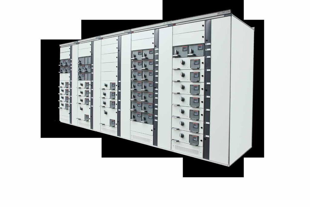
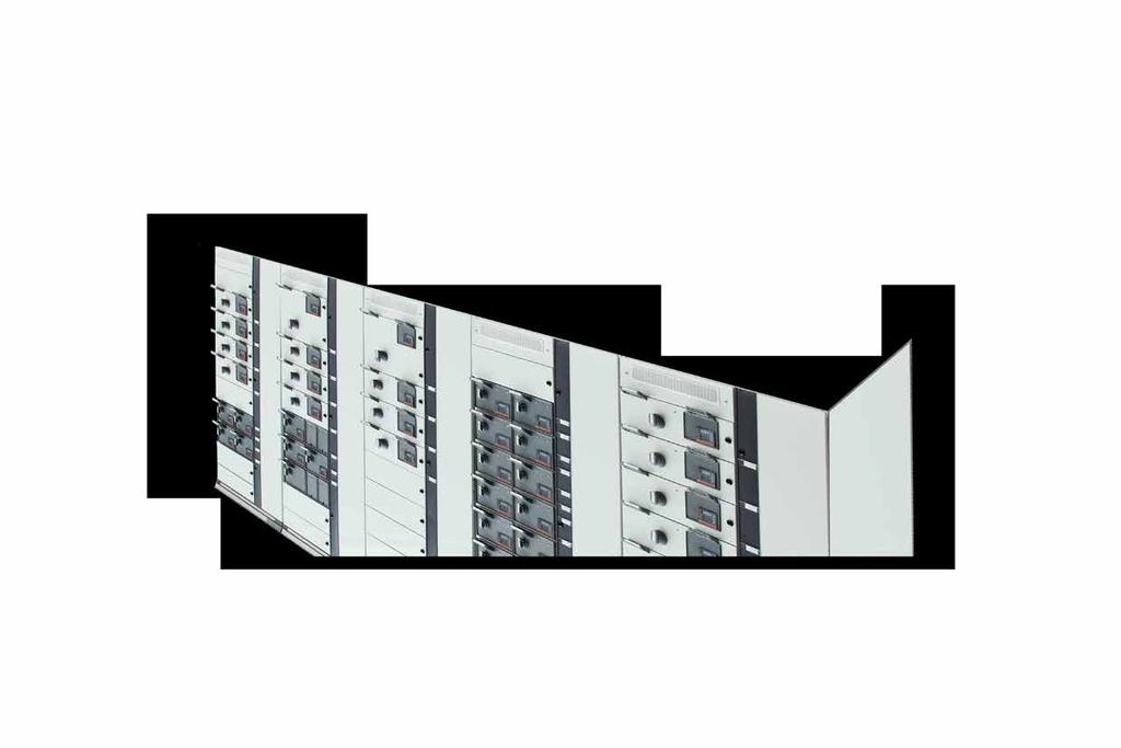
8 Product overview Introduction M10x is an intelligent motor control and protection device based on current measurement or current measurement and voltage measurement. Installed in and supplied as part of ABB Low Voltage switchgear MNS, it is part of a low voltage system family of products that provides customers with an ABB intelligent system solution. M10x is a microprocessor-based product providing comprehensive but standard features in one device. Standard features simplify maintenance and plant expansion. Each motor starter is equipped with one standard M10x device. With dedicated parameters in each device, M10x provides specific control, monitoring and protection functions, tailored for various motor applications. Coupled with the world's most common industrial fieldbus interfaces (PROFIBUS DP and MODBUS), M10x integrates smoothly and efficiently into industrial control and plant management systems. Every individual M10x device can be accessed and interrogated to determine both actual and operating parameters. Fast response time for alarm or trip status makes real time control of a complete process possible. Statistical recording of running hours and number of operations assists with predictive maintenance scheduling. For AC motor and the operated installations this means: Reliable protection Maximum utilization Continuous supervision Flexibility Structure Main unit (with current converter unit) Operator panel MD21/MD31 Analogue output (AO) module is available as an optional extension unit. Main unit The main unit is constructed with two parts: the electronics of the motor control unit and the integrated CT. Main unit is a one type device with the integrated CT range starting from 0.24 to 63A. For motor ratings larger than 63A, interposing CTs can be selected. Main unit is designed with a mounting rail fixed to the bottom of the device for easy vertical DIN rail mounting. Screws and other mounting accessories also provide for vertical and horizontal screw mounting. 8 Motor control and protection unit M10x user guide
, MD21/MD31 provides functions for motor control, supervision and parameterizing. One operator panel is provided for each main unit upon request.")
9 Operator panel MD21/MD31 The operator panel is the user interface mounted on the front door or drawer. With control buttons, LED, LCD module (MD21 only), MD21/MD31 provides functions for motor control, supervision and parameterizing. One operator panel is provided for each main unit upon request. Analogue Output Module AO11 Analogue output module AO11 is an optional add-on module to main unit, providing one channel 0-20mA or 4-20mA analogue output. Details of AO11 module including how to do the configuration is provided in a separate document, 1TNC M10x AO Module User Guide. M10x material The enclosure of the M10x is made of polycarbonate. Flammability rating of the material is UL 94 V-0 and material is halogen free. Color of the enclosure is RAL For a detailed description of MD21/MD31, refer to the chapter: Accessories. Fig. 1. M10x and MD21 M10x user guide Motor control and protection unit 9

10 Mounting of M10x Basic dimension of M10x W x H x D=110mm x 140mm x 75mm Typical installation of M10x Vertical DIN rail or vertical screw mounting on horizontal plate Basic dimension of MD21 W x H x D=91mm x 75mm x 24.3mm Mounting dimension of MD21 W x H=84mm x 68mm Basic dimension of MD31 W x H x D=88mm x 50mm x 24.3mm Mounting dimension of MD31 W x H=84mm x 46mm For installation details of M10x and MDx, see the related documentation installation manual. Fig. 2. M10x in 8E/4 module 10 Motor control and protection unit M10x user guide

 Picture 3-2.")
11 Interfaces Terminal blocks of M10x are located on the top of the main unit for easy access. There are 3 sets of I/O terminal blocks and 1 set of RJ11 connectors as shown. Fig Top view terminal layout (24VDC) Picture 3-2. Top view terminals layout (110VAC or 240VAC) M10x user guide Motor control and protection unit 11
12 Terminal designations Terminal block Terminal number Designation plug/contacts Remarks X1 24VDC type 110/240VAC type X1:1 X1:14 Digital input Cross section X1:15 X1:16 PTC input 1.5mm2 X1:1 X1:10 Digital input Cross section X1:11 X1:12 PTC input 2.5mm2 X2 X2:1 6 Interface for MDx Cable with RJ11 connector provided X3 X3:1 5 X3:6,7 Fieldbus for external communication RCT input Cross section 2.5mm2 X3:8 13 Voltage input X4 X4:1 9 Relay output X4:10,11 Power supply X4:12 Ground Cross section 2.5mm2 L1-T1;L2-T2;L3-T3 Table 1. Device terminals Lead-through Current measurement Φ10mm Window Power supply Depending on the product type, three types of power supply are available, ie, 24VDC, 110VAC and 240VAC. Power supply of the device should be always derived from an uninterrupted and reliable supply source. Terminal no. Name Description X4:11 24VDC or L 24VDC +, 110VAC or 240VAC X4:10 GND or N 0VDC or Neutral Table 2. Power supply input terminals Digital input M10x 24VDC type has 13 Dls and M10x 110/240VAC type has 9 DIs. Digital inputs are cyclically read. Functions of all digital inputs are selectable, and can be assigned to a defined function. M10x reads the status of input contacts by measuring the voltage drop on inputs: 12 Motor control and protection unit M10x user guide
13 Terminal no. Name Description X1:1 DI0 Digital input 0 X1:2 DI1 Digital input 1 X1:3 DI2 Digital input 2 X1:4 DI3 Digital input 3 X1:5 DI4 Digital input 4 X1:6 DI5 Digital input 5 X1:7 DI6 Digital input 6 X1:8 DI7 Digital input 7 X1:9 DI8 Digital input 8 X1:10 DI9 Digital input 9 X1:11 DI10 Digital input 10 X1:12 DI11 Digital input 11 X1:13 DI12 Digital input 12 X1:14 DI_COM Digital input common terminal Table 3. Digital inputs with 24VDC supply Terminal no. Name Description X1:1 DI0 Digital input 0 X1:2 DI1 Digital input 1 X1:3 DI2 Digital input 2 X1:4 DI3 Digital input 3 X1:5 DI4 Digital input 4 X1:6 DI5 Digital input 5 X1:7 DI6 Digital input 6 X1:8 DI7 Digital input 7 X1:9 DI8 Digital input 8 X1:10 DI_COM Digital input common terminal Table 4. Digital inputs with 110/240VAC supply i ) For 24VDC, it is recommended to use separate supply source for power supply and digital inputs, especially in the case that DI signals are taken from the field which is located a long distance from MCCs. M10x user guide Motor control and protection unit 13
14 Fig. 4. Illustration of DIs wiring to M10x PTC input (M102 only) PTC function is only available in M102 series of products. Type A temperature sensor with a characteristic curve according to IEC to follow the temperature of motor winding is used in the device. PTC connector is located on the top of M102 unit, terminal X1. i) M101 series of products do NOT have PTC function built in. ii) It is recommended to short terminal X1:15 and X1:16 together to avoid potential external disturbance when this function is not activated. iii) STP cable is recommended for PTC circuit connections. Terminal no. Name Description X1:15 PTCA PTC measurement input A X1:16 PTCB PTC measurement input B Table 5-1. PTC input terminals (24VDC type) Terminal no. Name Description X1:11 PTCA PTC measurement input A X1:12 PTCB PTC measurement input B Table 5-2. PTC input terminals (110/240VAC type) 14 Motor control and protection unit M10x user guide
15 Fieldbus interface Selected by different product types, M10x can be used directly on MODBUS RTU or PROFIBUS DP networks. Both types of product are based on physical RS485 layer. Dual RS485 interfaces are provided in MODBUS type of device to support full redundancy network design. Terminal no. Name Description X3:1 2B Serial RS485 B X3:2 2A Serial RS485 A X3:3 SHIELD 485 shield X3:4 1B Serial RS485 B X3:5 1A Serial RS485 A Table 6. MODBUS dual RS485 interfaces Terminal no. Name Description X3:1 5V Power supply 5V+ for bus terminator X3:2 B RS485 B X3:3 A RS485 A X3:4 GND Power supply GND for bus terminator X3:5 SHIELD Shield Table 7. PROFIBUS RS485 interface Residual current transformer M10x supports earth fault protection through external residual current transformer (RCT). Terminal no. Name Description X3:6 Ioa Residual current transformer input A X3:7 Iob Residual current transformer input B Table 8. Residual current transformer terminals i) Different sizes or types of RCT are available. Refer to M10x ordering guide for details. ii) It is recommended to short terminals X3:6 and X3:7 to avoid potential external disturbance when RCT is not in use. iii) It is recommended to use STP cable for RCT circuit connections. M10x user guide Motor control and protection unit 15
16 Voltage measurement (M102 only) Voltage measurement and protections are available in M102 range of products. Voltage unit is available in M102 only. Terminal no. Name Description X3:9 V L3 Phase L3 voltage input X3:11 V L2 Phase L2 voltage input X3:13 V L1 Phase L1 voltage input Table 9. Voltage input terminals i) When single phase system is selected, voltage measurement is based on phase L1 - phase L3. Connect L to V L1 (X3:13) and neutral to V L3 (X3:9). Current measurement M10x continuously measures three motor phase currents. The phase current data will be used by the protection functions and is reported to the fieldbus. Phase currents are reported as a value relative to the motor nominal current In. Current wires are fed through current sensors from either side of the terminal. Direction can be either L->T or T->L considering that all currents must have the same direction. Motor nominal currents above 63A are not measured directly, but instead intermediate current transformer s secondary side is connected through M10x current measurement terminal. i) When single phase system is selected, current measurement is based on phase L1. ii) The measurement range of internal CT is from 0.08A to 63A. iii) In cases of small current measurement (<0.5A), it is highly recommended to increase the primary wiring turns through internal CT in order to avoid nuisance current measurement. Refer to descriptions on ' Internal CT primary winding' in the product manual 'M10x parameter description. Contactor control output M10x supports various motor starter types. The control of the contactor by M10x is via internal output relays (CCA, CCB, CCC relays) by the microprocessor. Internal relays CCA and CCB are hardwire-interlocked to prevent both contactors being closed at the same time. 16 Motor control and protection unit M10x user guide
17 1) M101 is equipped with CCA and CCB output relays only. 2) For external connecting contactors, spark suppression is necessary for all types of contactors except the AF types to maintain reasonable service life of relays. Terminal no. Name Description M101 M102 X4:6 CCLI Contactor control voltage input X4:7 CCA Contactor control A X4:8 CCB Contactor control B X4:9 CCC Contactor control C Table 10. Contactor control terminals Digital output M10x is also equipped with two sets of auxiliary programmable digital output relays which function according to project specific settings. Terminal no. Name Description M101 M102 X4:1 GR1_A X4:2 GR1_B X4:3 GR1_C Programmable relay output 1 (NO+NC) X4:4 X4:5 GR2_A GR2_B Programmable relay output 2 (NO) Table 11. Digital output terminals The output status of programmable relays may change in response to different assigned functions. 1) M101 is equipped with only one set of output relay (GR1). 2) For external connecting contactors, spark suppression is necessary for all types of contactors except the AF types to maintain reasonable service life of relays. Interface for MD21/MD31 M10x is connected with operator panel MD21/MD31 using RJ11 interface. Ground terminal Terminal no. Name Description X4:12 GROUND Ground safety and surge Table 12. Ground terminal This is an additional ground terminal provided for dissipating transient signals and surges. It must be connected by a thick wire or braid to the system ground for reliable operation. M10x user guide Motor control and protection unit 17
18 Typical diagram Typical wiring diagrams of different types of M10x are shown in this section. M101 24VDC Block A *Note 1) Redundant Port Fig Typical wiring diagram for M101 (24VDC type) Note 1) Block A shows MODBUS dual RS485 interface. For PROFIBUS interface, Block B below should replace Block A. Block B *Note 1) Shield and Ground (X4:12) are connected internal of M10x. Digital output contacts (GR1_A, GR1_B &GR1_C) as shown are floating NC and NO contacts from the same relay and respond to parameter settings. Eg. when Trip is set to digital output, NO contact will close under healthy conditions. In the case of power loss, contact status will restore as shown. 18 Motor control and protection unit M10x user guide
19 M VAC or 240VAC Block A *Note 1) Redundant Port *Note 2) *Note 2) Fig Typical wiring diagram for M101 (110/240VAC type) Note 1) Block A shows MODBUS dual RS485 interface. For PROFIBUS interface, Block B below should replace Block A. 2) 110VAC or 240VAC voltage supply Block B *Note 1) Shield and Ground (X4:12) are connected inside M10x. Digital output contacts (GR1_A, GR1_B &GR1_C) as shown are floating NC and NO contacts from the same relay and respond to parameter settings, eg, when Trip is set to digital output, NO contact will close under healthy conditions.in the case of power loss, contact status will restore as shown. M10x user guide Motor control and protection unit 19
20 M102 24VDC Block A *Note 1) Redundant Port Fig Typical wiring diagram for M102 (24VDC type) Note 1) Block A shows MODBUS dual RS485 interface. For PROFIBUS interface, Block B below should replace Block A. Block B *Note 1) Shield and Ground (X4:12) are connected internal of M10x. Digital output contacts (GR1_A, GR1_B &GR1_C) as shown are floating NC and NO contacts from the same relay and respond to parameter settings, eg, when Trip is set to digital output, NO contact will close under healthy conditions. In the case of power loss, contact status will restore as shown. 20 Motor control and protection unit M10x user guide
21 M VAC or 240VAC Block A *Note 1) Redundant Port *Note 2) *Note 2) Fig Typical wiring diagram for M102 (110/240VAC type) Note 1) Block A shows MODBUS dual RS485 interface. For PROFIBUS interface, Block B below should replace Block A. 2) 110VAC or 240VAC voltage supply Block B *Note 1) Shield and Ground (X4:12) are connected inside M10x. Digital output contacts (GR1_A, GR1_B &GR1_C) as shown are floating NC and NO contacts from the same relay and respond to parameter settings, eg, when Trip is set to digital output, N/O contact will close under healthy conditions. In the case of power loss, contact status will restore as shown. M10x user guide Motor control and protection unit 21
22 Functionality Starter types M10x offers various kinds of motor starting control modes via the control of relay output. It supervises the operating state of the contactor according to the feedback of auxiliary contact, predefined feedback timeout and current. The following starting control modes are offered: Starter type M101 M102 NR-DOL REV-DOL NR-DOL/RCU REV-DOL/RCU Actuator NR-S/D NR-2N NR-2N Dahlander Autotransformer NR_softstarter REV_softstarter Contactor feeder Contactor feeder/rcu Feeder Table 13. Starter types supported by M10x NR_DOL: non reversing direct online REV_DOL: reversing direct online NR_DOL/RCU: non reversing direct online with RCU REV_DOL/RCU: reversing direct online with RCU Actuator: actuator with limit switch input NR_S/D: non reversing star-delta NR_2N: two-speed driver for non reversing starter with separate winding NR_2N Dahlander: two-speed driver for Dahlander connection Autotransformer: autotransformer starter NR_softstarter: non reversing softstarter control REV_softstarter: reversing softstarter control Contactor feeder: contactor controlled feeder Contactor feeder/rcu: contactor controlled feeder with RCU Feeder: feeder is regarded as a specific starter mode in M10x 22 Motor control and protection unit M10x user guide
23 Starter type is selected with a dedicated parameter to match the wiring for contactor and motor control circuits. i) PIN numbers assigned for DIs in below starters are shown as per default settings and and are subject to change to meet engineering requirements. ii) Spark suppression is necessary for all types of connecting contactors except AF types through M10x output relays to maintain reasonable service life of the output relays. Interface relays should also be considered in engineering to increase reasonable service life. Interface relay is recommended to be used for contactor type A75 and above. Fig. 8. Surge suppressors on contactor coils Precautions must be taken in system designs to avoid potential high electromagnetic disturbance which may result in unstable network and malfunction of M10x relays. For example, in applications that variable speed drives are used in a large scale, harmonic filter devices are required in system design to reduce impact to the network. M10x user guide Motor control and protection unit 23
24 NR-DOL STARTER NR_DOL starter is a basic starter type for driving motor in one direction. When start command has been received from field or local I/O, the contactor control output will be energized and remains in this in condition until stop command has been received or any protection function is activated. Name Pin Description CCLI X4:6 Contactor control voltage input CCA X4:7 Contactor control A DI6(F_Ca) X1:7 Contactor control A feedback DI5(Loc/R) X1:6 Local/remote control switch input Table 14. NR-DOL starter contactor control interface (for M10x) The definition of the terminal X1 in the above list is only an example. CCA MOTOR Fig. 9. Control circuit for NR-DOL starter (for M10x) 24 Motor control and protection unit M10x user guide
25 NR-DOL/RCU STARTER Remote control unit (RCU) is a starter type where contactors are directly controlled by a special RCU switch located near the motor. This allows control of the motor even without the M10x. Name Pin Description Remarks CCLI X4:6 Contactor control voltage input CCA X4:7 Contactor control A GR1_C X4:3 Programmable relay output Only for M101 CCC X4:9 Contactor control C Only for M102 DI6(F_Ca) X1:7 Contactor control A feedback DI5(Loc/R) X1:6 Local/remote control switch input Table 15. NR-DOL/RCU starter contactor control interface (for M10x) The definition of the terminal X1 in the above list is only an example. MOTOR Fig Control circuit for NR-DOL/RCU starter (for M101) MOTOR Fig Control circuit for NR-DOL/RCU starter (for M102) M10x user guide Motor control and protection unit 25
26 REV-DOL STARTER REV-DOL uses contactor control output A to control the contactor that drives the motor in direction CW. Correspondingly, contactor control output B is used for direction CCW. When the starting motor to either direction contactor will be energized and is stopped (not energized) by command from fieldbus or local I/O, or active protection function. Name Pin Description CCLI X4:6 Contactor control voltage input CCA X4:7 Contactor control A CCB X4:8 Contactor control B DI6(F_Ca) X1:7 Contactor control A feedback DI7(F_Cb) X1:8 Contactor control B feedback DI5(Loc/R) X1:6 Local/remote control switch input Table 16. REV-DOL starter contactor control interface (for M10x) The definition of the terminal X1 in the above list is only an example. MOTOR Fig. 11. Control circuit for REV-DOL starter (for M10x) 26 Motor control and protection unit M10x user guide
27 REV-DOL/RCU starter The functionality of this starter type is the same as the to NR-DOL/RCU starter with support for reversing use of motor. Name Pin Description Remarks CCLI X4:6 Contactor control voltage input CCA X4:7 Contactor control A CCB X4:8 Contactor control B GR1_C X4:3 Programmable relay output1 Only for M101 CCC X4:9 Contactor control C Only for M102 DI6(F_Ca) X1:7 Contactor control A feedback DI7(F_Cb) X1:8 Contactor control B feedback DI5(Loc/R) X1:6 Local/remote control switch input Table 17. REV-DOL starter contactor control interface (for M10x) The definition of the terminal X1 in the above list is only an example. MOTOR Fig. 12. Control circuit for REV-DOL/RCU starter (for M101) MOTOR Fig. 13. Control circuit for REV-DOL/RCU starter (for M102) M10x user guide Motor control and protection unit 27
28 Actuator starter (M102 only) This starter type is for controlling valves and actuators by using limit switches Name Pin Description CCLI X4:6 Contactor control voltage input CCA X4:7 Contactor control A CCB X4:8 Contactor control B CCC X4:9 Contactor control C DI0 (Limit1) X1:1 Limit position switch 1 input DI1 (Limit2) X1:2 Limit position switch 2 input DI9 (Torque) X1:10 Torque switch input DI6 (F_Ca) X1:7 Contactor control A feedback DI7 (F_Cb) X1:8 Contactor control B feedback DI5 (Loc/R) X1:6 Local/remote control switch input Table 18. Actuator starter contactor control interface The definition of the terminal X1 in the above list is only an example. MOTOR Fig. 14. Control circuit for actuator starter Limit switch stops the motor when activated. Additionally, the start command is only allowed to reverse direction. Torque switch is selectable by parameterization. 28 Motor control and protection unit M10x user guide
29 NR-S/D starter (M102 only) Motor start current is reduced in star connection to 1/3 of the current in delta connection, with lower torque during the same time. Start-to-delta starting sequence is based on the presented control logic (Figure 15). The changeover condition is time. The following guideline is applied for selecting parameter values: Changeover time < Motor startup time Name Pin Description CCLI X4:6 Contactor control voltage input CCA X4:7 Contactor control A CCB X4:8 Contactor control B CCC X4:9 Contactor control C DI5 (Loc/R) X1:6 Local/remote control switch input DI6 (F_Ca) X1:7 Contactor control A feedback DI7 (F_Cb) X1:8 Contactor control B feedback DI8 (F_Cc) X1:9 Contactor control C feedback Table 19. NR_S/D starter contactor control interface The definition of the terminal X1 in the above list is only an example. MOTOR Fig. 15. Control circuit for NR-S/D starter M10x user guide Motor control and protection unit 29
30 NR-2N starter (M102 Only) NR-2N uses two contactors to control motor rotation speed; the motor contains separate windings. Rotation speed can be changed on the fly without stop command in between. Low speed (start 1) can be changed to high speed (start 2) immediately, and high speed can be changed to low speed after a changeover time. Current measurement for NR-2N uses two external current transformers measuring current from motor main supply. External current transformers can be selected separately for both speeds. The following guideline is applied for selecting parameter values: Changeover time < Motor startup time Name Pin Description CCLI X4:6 Contactor control voltage input CCA X4:7 Contactor control A CCB X4:8 Contactor control B DI6 (F_Ca) X1:7 Contactor control A feedback DI7 (F_Cb) X1:8 Contactor control B feedback DI5 (Loc/R) X1:6 Local/remote control switch input Table 20. NR-2N starter contactor control interface The definition of the terminal X1 in the above list is only an example. MOTOR Fig. 16 Control circuit for NR_2N starter, separate windings 30 Motor control and protection unit M10x user guide
31 Operating sequence in NR-2N Sending command Start1 (low speed N1) to close contactor CCA Sending command Start2 (high speed N2) to close contactor CCB Contactors are latched Stop command opens CCA or CCB Motor can be controlled with sequences: Stop -> Start1 -> Stop Stop -> Start2 -> Stop Stop -> Start1 -> Start2 ->Stop Stop -> Start2 -> Changeover delay-> Start1 -> Stop NR-2N Dahlander STARTER (M102 Only) NR-2N Dahlander uses three contactors to control motor rotation speed where motor is equipped with a three-phase winding. Rotation speed can be changed on the fly without stop command in between. Low speed (start 1) can be changed to high speed (start 2) immediately, and high speed can be changed to low speed after a changeover time. Current measurement for NR-2N Dahlander uses two external current transformers measuring current from motor main supply. External current transformers can be selected separately for both speeds. The following guideline is applied for selecting parameter values: Changeover time < Motor startup time Name Pin Description CCLI X4:6 Contactor control voltage input CCA X4:7 Contactor control A CCB X4:8 Contactor control B CCC X4:9 Contactor control C DI5 (Loc/R) X1:6 Local/remote control switch input DI6 (F_Ca) X1:7 Contactor control A feedback DI7 (F_Cb) X1:8 Contactor control B feedback DI8 (F_Cc) X1:9 Contactor control C feedback Table 21. NR-2N Dahlander starter contactor control interface The definition of the terminal X1 in the above list is only an example. M10x user guide Motor control and protection unit 31
32 MOTOR Fig. 17. Control circuit for NR_2N Dahlander starter Operating sequence in NR-2N Dahlander Sending command Speed1 to close contactor CCA Sending command Speed2 to close contactor CCB and CCC Contactors are latched Sending stop command to open CCA or CCB + CCC Motor can be controlled with sequences: Stop -> Start1 -> Stop Stop -> Start2 -> Stop Stop -> Start1 -> Start2 ->Stop Stop -> Start2 -> Chang over delay-> Start1 -> Stop 32 Motor control and protection unit M10x user guide
33 Autotransformer starter (M102 only) This starter type is used to control the autotransformer unit in order to minimize voltage drop during motor startup. Autotransformer starter with three contactors supports motor starting with reduced voltage, thus providing reduced motor startup current. The starting torque will be reduced accordingly, The following guideline applies for selecting parameter values: Changeover time < Motor startup time Name Pin Description CCLI X4:6 Contactor control voltage input CCA X4:7 Contactor control A CCB X4:8 Contactor control B CCC X4:9 Contactor control C DI5 (Loc/R) X1:6 Local/remote control switch input DI6 (F_Ca) X1:7 Contactor control A feedback DI7 (F_Cb) X1:8 Contactor control B feedback DI8 (F_Cc) X1:9 Contactor control C feedback Table 22. Autotransformer starter contactor control interface The definition of the terminal X1 in the above list is only an example. Fig. 18. Control circuit for autotransformer starter M10x user guide Motor control and protection unit 33
34 NR-softstarter (M102 only) Softstarter applications are for controlling the motor accessory softstarter device. M102 gives start and stop commands to the softstarter unit. The softstarter is set for adjusting motor voltage with its own parameters. More information about softstarter can be found in the softstarter manual. This starter type supports all protection functions during normal running situations. For motor start and stop period, some of the protection functions are disabled by these parameters. Current feedback function is suppressed under soft-starter control. Name Pin Description CCLI X4:6 Contactor control voltage input CCA X4:7 Contactor control A CCC X4:9 Contactor control C DI6 (F_Ca) X1:7 Contactor control A feedback DI5 (Loc/R) X1:6 Local/remote control switch input Table 23. NR_softstarter starter contactor control interface The definition of the terminal X1 in the above list is only an example. Fig. 19. Control circuit for NR-softstarter Operating sequence for NR-softstarter Start1 to close CCA followed by CCC Stop to open CCC followed by CCA after ramp down time delay. 34 Motor control and protection unit M10x user guide
35 REV-softstarter (M102 Only) This starter is of similar functionality as the NR-softstarter starter, with additional function to support reversing the motor. Name Pin Description CCLI X4:6 Contactor control voltage input CCA X4:7 Contactor control A CCB X4:8 Contactor control B CCC X4:9 Contactor control C DI5 (Loc/R) X1:6 Local/Remote control switch input DI6 (F_Ca) X1:7 Contactor control A feedback DI7 (F_Cb) X1:8 Contactor control B feedback Table 24. REV-softstarter starter contactor control interface The definition of the terminal X1 in the above list is only an example. Fig. 20. Control circuit for REV-softstarter Operating sequence for REV-softstarter Start1 to close CCA followed by CCC Start2 to close CCB followed by CCC Stop to open CCC followed by CCA or CCB after ramp down time delay. M10x user guide Motor control and protection unit 35
36 Contactor feeder Contactor feeder is regarded in M10x as a specific starter type to provide measurement, control and protection functionality to a contactor feeder circuit. When start command has been received from field or local I/O, the contactor control output will be energized and remains in this condition until stop command has been received or any protection function is activated. Name Pin Description CCLI X4:6 Contactor control voltage input CCA X4:7 Contactor control A DI6(F_Ca) X1:5 Contactor control A feedback DI5(Loc/R) X1:6 Local/remote control switch input Table 25. Contactor feeder contactor control interface (i) The definition of the terminal X1 in the above list is only an example. Fig. 22. Control circuit for contactor feeder 36 Motor control and protection unit M10x user guide
37 Contactor feeder/rcu Remote control unit (RCU) is a starter type where contacters are directly controlled by a special RCU switch located near the motor. This allows control of the motor even without the M10x. Name Pin Description Remark CCLI X4:6 Contactor control voltage input CCA X4:7 Contactor control A GR1_C X4:3 Programmable relay output Only for M101 CCC X4:9 Contactor control C Only for M102 DI6(F_Ca) X1:7 Contactor control A feedback DI5(Loc/R) X1:6 Local/remote control switch input Table 26. Contactor feeder/rcu contactor control interface (for M10x) i) The definition of the terminal X1 in the above list is only an example. Fig Control circuit for contactor feeder/rcu (for M101) Fig Control circuit for contactor feeder/rcu (for M102) M10x user guide Motor control and protection unit 37
38 Feeder Feeder mode is regarded in M10x as a specific starter type to provide measurement and control functionality. The protection of feeder is not covered in M10x and is normally done by main circuit breaker. The feeder mode in M10x is designed to provide a complete intelligent solution in MCC plants where the feeder circuits are usually small, but important parts from the MCC plant management point of view. Name Pin Description CCLI X4:6 Contactor control voltage input CCA X4:7 Control YC /motor drive in MCCB (2 seconds holding) CCB X4:8 Control YO/motor drive in MCCB (2 seconds holding) DI6 (F_Ca) X1:7 Circuit breaker position aux. feedback DI9 (External trip input) X1:10 Circuit breaker trip aux. feedback DI5 (Loc/R) X1:6 Local/remote control switch input* Table 27. Feeder control interface i) The definition of the terminal X1 in the above list is only an example Fig. 21. Control circuit for feeder Feeder application in M10x is confined to certain features. End users need to be informed on these confines when feeder application is required through M10x. 38 Motor control and protection unit M10x user guide
39 Operating: Start 1 command activates contactor output relay CCA for 2 seconds. Start 2 command activates contactor output relay CCB for 2 seconds. External trip occurs a trip message and will be reset when the signal is inactive. Monitoring: Circuit breaker close/open status Circuit breaker trip Protection: Motor protection functions are not suitable for feeder application. All protections except earth fault protection in M10x are automatically disabled during parameter setting when feeder type is selected. Measuring: Current, voltage are measured by M10x. Power, energy and other parameters related to power factor are NOT correct and should not be referred to. M10x user guide Motor control and protection unit 39
40 Protection functions The module provides full protection for motors by supervising three voltage phases, three current phases, earth fault current, PTC sensor, startup time, the state of contactors and the state of the main switch. Response of protection functions is based on the parameters given by the user. The operation of separate functions is independent, thus protection functions can be active at the same time but the one which indicates the situation first will give a trip for the motor. According to the application, all kinds of protection can be enabled, disabled by the upper level system or MCU setup tool, and the protection characteristics can be adjusted. Protection module offers the following protection and supervisory functions: Protection type M101 M102 Overload protection Stall protection Long start protection Phase failure protection Unbalance protection Underload protection Noload protection Earth fault protection PTC protection Undervoltage protection Start limitation protection Phase sequence Protection Table 28. Protection functions in M10x 40 Motor control and protection unit M10x user guide
41 Overload protection Thermal overload protection (TOL) protects the motor against overheating.the motor thermal condition is simulated by a calculation. The result of the calculation is stored in a thermal register and can be reported via operator panel or fieldbus interface. Calculation is accomplished in a different motor operation conditions, principly presented below. Thermal increase and decrease are simulated by TOL protection function for running and stopped motor. Fig. 24. Principle picture of motor thermal simulation M10x simulates thermal conditions in the motor for all operating modes (running or stopped). This permits maximum utilization of an installation and assures safe protection of the motor. Thermal overload protection simulation accounts for the temperature rise of both the stator winding and the iron mass of the motor. It gives thorough consideration of the effect of motor overheating due to three-phase unbalance during the simulation calculation of motor thermal overload. M10x user guide Motor control and protection unit 41
 and Te time.")
42 There are two thermal models supported by M10x: standard or EEx e. The standard model makes use of parameters trip class, t6 in thermal overload calculation. The protection of explosion proof three-phase motors with type of protection increased safety EEx e is done with two special parameters, the Ia/In ratio (stall/nominal current ratio) and Te time. The following diagram offers the characteristic curve of overload protection, in which the characteristics are adjusted by changing t6 (trip time for current I L max =6xIn from the cold state). Fig. 25. Trip curve from cold condition The maximum thermal capacity level is 100%. Maximum level is reached when the motor has been running with a current 6xIn at the time t6 starting from the cold state in ambient temperature 40 C. Trip class T6 10A Table 29. IEC trip class when ambient temperature 40 C, balanced motor current 42 Motor control and protection unit M10x user guide
43 If motor is in overload condition, i.e. I Lmax > 1.14 x TFLC (thermal full load current multiplier reduced by motor ambient temperature), the overload alarm is activated to indicate overload. In some applications, it is beneficial to be able to bypass the TOL protection momentarily because of the process reasons. The lifetime of the motor will be shortened, but it might the more costly to stop the process. TOL bypass function is designed for this reason. If a TOL bypass is activated, - when the motoring is running, the thermal capacity is allowed to rise to 200% before a trip occurs; - when the motor is already taken off line due to TOL, the motor is ready for an emergency start as long as the thermal level is below 200%. More details refer to 'TOL bypass' function under digital input functions section. Function Setting range Default value 0=Disabled 1=Enabled 2=Disabled during motor startup Enabled Step value 1 Disabled during motor startup Setting range 0=Enabled during motor startup 1=Disabled during motor startup Default value 0 Step value 1 Trip reset mode Setting range 1=Auto 2=Local 3=Remote 4=Remote and local Default value 4 Step value 1 Thermal model Setting range 0=Standard model 1=EEX e Default value 0 Step value 1 M10x user guide Motor control and protection unit 43
44 TOL bypass Setting range Default value T6 Setting range Default value 0=Disabled 1=Enabled Disabled 3-40sec 6sec Step value 1 Cool coefficient Setting range 1-10 Default value 4 Step value 1 Ia/In Setting range Default value 5.0 Step value 0.1 Te Setting range Default value Step value 5-40sec 5sec 1sec TOL alarm level Setting range % Default value 90% Step value 1% TOL trip level Setting range % Default value 100% Step value 1% TOL reset level Setting range 10-60% Default value 50% Step value 1% Ambient temperature Setting range 0-80 C Default value 40 C Step value 5 C Table 30. TOL protection parameters When Standard thermal model is selected When EEX e thermal model is selected 44 Motor control and protection unit M10x user guide
45 Stall protection Stall protection is used to protect the driven mechanical system from jams and excessive overload. Stall protection function uses Imax as the criterion. There are other parameters to be determined as follow: Function Setting range 0=Disable 1=Enable Default value 1 Step value 1 Trip reset mode Setting range 2=Local 3=Remote 4=Remote and local Default value 4 Step value 1 Trip level Setting range % Default value 400% Step value 10% Trip delay Setting range Default value sec 0.5sec Step value 0.1sec Table 3. Stall protection parameters I Lmax Startup current Trip level Trip delay I N Startup Function activated Trip t Fig. 24. Stall protection Stall function activates after motor nominal startup time has elapsed. The highest measured phase current (I Lmax ) is compared against the trip level. When I Lmax remains over the trip level at a time longer than trip delay, a stall alarm is issued and the contactor tripped. M10x user guide Motor control and protection unit 45
46 Long start protection The long start protection protects motor against locked or stalled rotor in starting state. M10x detects the current after a start command, and signals a fault when current continuously exceeds a separately set threshold of the period of start time. Fig. 25 Long start protection Function Setting range Default value 0=Disabled 1=Enabled Disabled Step value 1 Locked rotor level Setting range % Default value 120% Step value 10% Locked Rotor Delay Setting range Default value Step value 0-250sec 10sec 1sec Trip reset mode Setting range 2=Local 3=Remote 4=Remote and Local Default value 4 Step value 1 Table 32. Long start protection parameters Phase failure protection M10x protects the motor against phase current loss condition. Phase failure protection function uses I Lmin /I Lmax (the ratio of lowest I Lmin and highest measured phase value I Lmax ) as the criterion. Function is suppressed by parameters Motor startup time, number of phases and Softstart ramp time. 46 Motor control and protection unit M10x user guide
47 Function Setting range Default value 0=Disabled 1=Enabled 3=Alarm only Disabled Step value 1 Trip delay Setting range Default value Step value 0-60sec 10sec 1s Alarm level Setting range 10-90% Default value 80% Step value 1% Trip level Setting range 5-90% Default value 70% Step value 1% Trip reset mode Setting range 2=Local 3=Remote 4=Remote and local Default value 4 Step value 1 Table 33. Phase failure parameters (I LMIN / I LMAX ) Alarm level Trip level Trip delay t 1. alarm 2. start trip delay 3. clear trip delay 4. start trip delay 5. trip 6. trip reset Fig. 26 Phase failure protection ILmin/ILmax is compared against the phase failure alarm level. When ILmin/ILmax decreases below the Alarm level, a Phase failure alarm alarm is issued. ILmin/ILmax is compared against the phase failure trip level. When ILmin/ILmax remains below the trip level at a time longer the trip delay, a Phase failure trip alarm is issued and the contactor tripped. M10x user guide Motor control and protection unit 47
48 Unbalance protection M10x protects the motor against unbalance conditions. Unbalance protection function also uses I Lmin /I Lmax as the criterion. Function is suppressed by parameters Motor startup time, Number of phases and Softstart ramp time. Function Setting range Default value 0=Disabled 1=Enabled 3=Alarm only Disabled Step value 1 Trip delay Setting range Default value Step value 0-60sec 10sec 1s Alarm level Setting range 50-90% Default value 90% Step value 1% Trip level Setting range 5090% Default value 85% Step value 1% Trip reset mode Setting range 2=Local 3=Remote 4=Remote and local Default value 4 Step value 1 Table 34. Unbalance protection parameters (I LMIN / I LMAX ) Alarm level Trip level Trip delay t 1. alarm 2. start trip delay 3. clear trip delay 4. start trip delay 5. trip 6. trip reset Fig. 27. Unbalance protection 48 Motor control and protection unit M10x user guide
49 I Lmin /I Lmax is compared against the unbalance alarm level. When I Lmin /I Lmax decreases below the alarm level, a unbalance alarm is issued. I Lmin /I Lmax is compared against the unbalance trip level. When I Lmin /I Lmax remain below the trip level at a time longer the trip delay, a unbalanced trip alarm is issued and the contactor tripped. Underload protection M10x protects the motor against underload conditions. Underload protection function uses I Lmax /In (the ratio of highest measured phase value I Lmax and the rated current of the motor In) as the criterion. There are other parameters to be determined, such as alarm level, trip level and trip delay. The protection characteristic are as follows: Function Setting range Default value 0=Disabled 1=Enabled 3=Alarm only Disabled Step value 1 Alarm level Setting range 20-90% Default value 30% Step value 1% Trip level Setting range 5-90% Default value 20% Step value 1% Trip delay Setting range Default value Step value sec 10sec 1sec Trip reset mode Setting range 2=Local 3=Remote 4=Remote and local Default value 4 Step value 1 Table 35. Underload protection parameters M10x user guide Motor control and protection unit 49
50 (I Lmax / I n ) Alarm level Trip level Trip delay warning 2. start trip delay 3. clear trip delay 4. start trip delay trip 6. trip reset t Fig. 28. Underload protection The I Lmax /In is compared against the underload alarm level. When I Lmax /In decreases below the alarm level an underload alarm is issued. The I Lmax /In is compared against the underload trip level. When ILmax/In remains below the trip level at a time longer than underload trip delay, an underload trip alarm is issued and the contactor tripped. Noload protection M10x protects the motor against no load conditions. Practically, noload protection is the same function as underload protection. The function also uses I Lmax /In as the criterion. Function Setting range Default value 0=Disabled 1=Enabled 3=Alarm only Disabled Step value 1 Alarm level Setting range 5-50% Default value 20% Step value 1% Trip level Setting range 5-50% Default value 15% Step value 1% Trip delay Setting range Default value Step value sec 5sec 1sec Trip reset mode Setting range 2=Local 3=Remote 4=Remote and local Default value 4 Step value 1 Table 36. Noload protection parameters 50 Motor control and protection unit M10x user guide
51 (I Lmax / I n ) Alarm level Trip level Trip delay warning 2. start trip delay 3. clear trip delay 4. start trip delay trip 6. trip reset t Fig. 29. Noload protection The I Lmax /In is compared against the no load alarm level. When I Lmax /In decreases below the alarm level a noload alarm is issued. The I Lmax /In is compared against the noload trip level. When I Lmax /In remains below the trip level at a time longer than noload trip delay, a noload trip alarm is issued and the contactor tripped. Earth fault protection M10x protects the motor against the earth fault condition with an additional residual current transformer. The function is by default suppressed by parameters motor startup time and softstarter ramp up time to avoid nuisance tripping due to harmonics caused by saturation of the current transformers. In some cases, it may need to be switched on during startup in order to meet specific project requirements. M10x relay is NOT a residual current protection device. This protection is neither intended to be used for pre-emptive isolation supervision nor for personnel protection against electrical shock. For these applications ABB recommends the usage of external protection devices (PRCDs/RCDs). Earth fault protection uses the following parameters: Function Setting range Default value 0=Disabled 1=Enabled 3=Alarm only Disabled Step value 1 M10x user guide Motor control and protection unit 51
52 Earth fault protection is activated during motor startup time Setting range 0=Disabled 1=Enabled Default value 0 Step value 1 Alarm level Setting range mA (Earth fault primary = 1A) mA (Earth fault primary = 5A) Default value Step value 500mA 100mA Trip level Setting range mA (Earth fault primary = 1A) mA (Earth fault primary = 5A) Default value Step value 800mA 100mA Trip delay Setting range Default value Step value sec 10.0sec 0.1sec Trip reset mode Setting range 2=Local 3=Remote 4=Remote and local Default value 4 Step value 1 Table 37. Earth fault protection parameters (I 0 ) Trip Level Alarm Level Trip Delay Trip Delay Earth Fault Current Trip Alarm Earth Fault Current Alarm Fig. 30. Earth fault protection ( I 0 = measured earth fault current) t I 0 is compared against the earth fault current fault alarm level. When I 0 exceeds above the alarm level, an earth fault alarm is issued. I 0 is compared against the earth fault current trip level. When I 0 remains above the earth fault current Trip level at a time longer than trip delay, an earth fault trip alarm is issued and the contactor tripped. 52 Motor control and protection unit M10x user guide
53 PTC protection (M102 only) PTC protection protects the motor against too-high temperature by using PTC-sensor embedded in the stator winding or the bearings. For M102, use a type A temperature sensor with a characteristic curve according to IEC Function Setting range Default value 0=Disabled 1=Enabled 3=Alarm only Disabled Step value 1 PTC Alarm level Setting range Ω Default value Step value 1600Ω 1Ω PTC trip level Setting range Ω Default value Step value 3600Ω 1Ω PTC trip delay Setting range Default value Step value sec 1sec 1sec PTC reset level Setting range Ω Default value Step value 1600Ω 1Ω PTC trip reset mode Setting range 1=Auto 2=Local 3=Remote 4=Remote and local Default value 4 Step value 1 PTC short circuit alarm level Setting range 0-250Ω Default value 10 Ω Step value 1 Ω Table 38. PTC protection parameters M10x user guide Motor control and protection unit 53
54 ( H ) Trip delay PTC trip Trip re et Trip Level Alarm Level e et Level PTC Temperature alarm Alarm clear t Fig. 31. PTC protection The resistance of PTC input is compared against the alarm level. When resistance of PTC input exceeds above the alarm level, a PTC alarm message is issued. The resistance of the PTC input is compared against the trip level. When resistance of PTC input is above the trip level PTC trip alarm is issued and the contactor tripped. After PTC trip is executed, the resistance of PTC input is compared against the PTC reset level. When resistance of PTC input decreases below the reset level, the PTC protection function executes the function set by PTC reset mode. M10x provides short circuit and open circuit detection for the temperature sensing element. Short circuit alarm level is settable, and open circuit alarm level is fixed. When the resistance of PTC input falls below short circuit alarm level, a PTC short circuit alarm message is issued. When the resistance of PTC input exceeds 12kΩ, a PTC open circuit alarm message is issued. Short circuit and open circuit detection threshold have no fault time delay. The short circuit and open circuit protection is enabled when PTC protection is enabled, and cannot be disabled. If the measured resistance is over 20kΩ, thermistor resistor will display, 20kΩ. The distance between PTC sensors and M10x PTC measuring inputs cannot exceed the following to be able to maintain reasonable reading: Cross section 2.5mm2 1.5mm2 0.5mm2 Length 2x250m 2x150m 2x50m 54 Motor control and protection unit M10x user guide
55 Undervoltage protection (M102 Only) M102 protects the motor against undervoltage conditions such as voltage dip. The undervoltage protection function uses U Lmin as the criterion. There are other parameters to be determined, such as alarm level, trip level and trip delay, and reset voltage level. The protection characteristic is as follows: 3 Fig. 32. Undervoltage protection The lowest measured main line voltage (U lmin ) is compared against the undervoltage alarm level. When U lmin decreases below the undervoltage alarm level, an undervoltage alarm is issued. The lowest measured main line voltage (U lmin ) is compared against the undervoltage trip level and voltage restore level. When U lmin recovers above undervoltage restore level before trip delay expires and motor continues running. If U lmin remains below the restore level at a time longer than trip delay, undervoltage trip is issued and contactor will be opened. When autorestart function is active, undervoltage trip delay will be same as maximum power down time automatically. M10x user guide Motor control and protection unit 55
56 Function Setting range Default value 0=Disabled 1=Enabled 3=Alarm only Disabled Step value 1 Alarm level Setting range % Default value 80% Step value 1% Trip level Setting range % Default value 65% Step value 1% Trip delay Setting range Default value Step value sec 1.0sec 0.1sec Reset level Setting range % Default value 90% Step value 1% Trip reset mode Setting range 1=Auto 2=Local 3=Remote 4=Remote and local Default value 4 Step value 1 Table 39. Undervoltage protection parameters 56 Motor control and protection unit M10x user guide
57 Start limitation Start limitation helps to protect the motor and also the process against excess number of starts in a given interval. When the number of starts is reached and the motor is switched off, a new start is prevented. The time interval, starts from the first start. After the elapse of the time interval, the counter is reset to the preset value. The permissible motor starts per hour can be obtained from the manufacturer's motor and apparatus data sheet. However, the minimum waiting time between two starts must be observed. The parameterization of the protection function can be the number of starts per time interval or the time between two consecutive starts. In the first case, the user must wait after the trip for the reset to take place before making a start. Independent of this function, the motor is protected by TOL function and a start is possible only if the thermal capacity is below the startup inhibit level. If motor data specifies the number of starts during a certain time span, this function can be used to supervise the number of starts. In some other cases, the process may require a motor start number, which the protection can provide. Functionality is presented in the following example. The next Figure 33 illustrates the start limitation protection with 3 starts allowed. 1) Normal situation, after stop command motor can be started normally, start 2. Every start activates an internal timer for the time defined by time interval parameter. The number of active timers are reviewed after every stop command and compared to value of number of starts parameter. Stop command can be implemented during active or elapsed timer. 2) Two timers are still active, thus stop command generates alarm message start limitation alarm and one more start, Start 3 is allowed. 3) The 3rd start has been executed. A contactor trip and trip message start limitation trip alarm will follow when motor is stopped while there are two active timers, starting from Start 1. 4) Trip can be automatically reset when the first timer from Start 1 is finished. Motor start is possible when all pending trips are reset. Supervision continues with a new timer from Start 4. M10x user guide Motor control and protection unit 57
58 Fig. 33. Start limitation protection Function Setting range Default value 0=Disable 1=Enable Disabled Step value 1 Time interval Setting range Default value 1-600min 1min Step value 1 Number of starts Setting range Default value 2 Step value 1 Table 40. Start limitation parameters Phase sequence protection M10x protects the motor against connection in wrong phase sequence. Before motor startup, M10x detects the phase sequence of voltage continuously and after startup M10x will detect the phase sequence of current. The definition of correct phase sequence: Voltage: L1, L2, L3 Current: la, lb, lc If enable phase sequence protection, when M10x detects the voltage or current is different from the definition M10x will release a phase sequence trip signal. 58 Motor control and protection unit M10x user guide
59 Function Enable/Disable Setting range Default value 0=Disable 1=Enable Disabled Step value 1 Trip Reset Mode Setting range 2=Local 3=Remote 4=Remote&Local Default value 4 Step value 1 Table 41a. Phase sequence protection parameters Autorestart function (M102 Only) The line voltage (U L1L3 ) is supervised continuously. It is possible to automatically restart the motor after momentary power loss. Two alternative models of auto restart function are provided in M102: standard and enhanced. M101 does not have the autorestart function. Function Setting range Default value 0=Disabled 1=Enabled Disabled Step value 1 Function mode Setting range 0=standard 1=enhanced Default value 0 Step value 1 Maximum autoreclose time Setting range Default value Step value msec 200msec 100msec Maximum powerdown time Setting range Default value Step value sec 5sec 0.1sec Staggered start delay Setting range Default value sec 5sec Step value 0.1sec Table 41. Auto restart function parameters M10x user guide Motor control and protection unit 59
60 Autorestart function (standard) In standard mode, the reaction of the auto restart function depends on the length of the voltage dip. The following cases show the different reactions of M102 in different voltage dip situations Case 1: Voltage dip< autoreclose time. Fig. 34. Autorestart (Voltage dip< autoreclose time) Case 2: Autoreclose time<voltage dip< Maximum powerdown time. Fig. 35. Autorestart (autoreclose time<voltage dip< Maximum powerdown time) If power is restored after autoreclose time but before maximum powerdown time, motor will be restarted after the staggered start delay time. 60 Motor control and protection unit M10x user guide
61 Case 3: Voltage dip> Maximum powerdown time. Fig. 36. Restart (Voltage dip> Maximum powerdown time) If supply voltage remains below restore level long enough and exceeds maximum powerdown time, no automatic restart will be initiated. Autorestart function (enhanced) If the voltage dip is more serious, the enhanced autorestart function can be applied. In the enhanced mode, the reaction of the autorestart function not only depends on the length of the voltage dip, but also the number of voltage dips within a short period of time. The following cases show the different reactions of M102 in different voltage dip situations: Case 1: Voltage dip< autoreclose time Identical to Case1 of standard mode Case 2: autoreclose time<voltage dip< Maximum powerdown time Identical to Case2 of standard mode Case 3: Voltage dip> Maximum powerdown time Identical to Case3 of standard mode Case 4: 2xdip<200ms within 1sec M10x user guide Motor control and protection unit 61
62 Fig. 37. Restart (2xdip<200ms within 1sec) If the interval between two voltage dips (length less than 200ms) is less than 1 sec, automatic delay restart is triggered after second voltage restore. Number of starts M10x counts number of starts. For each operation cycle, M10x updates the number of operating cycles in a memory map. When start number alarm level is exceeded, M10x issues an alarm. Motor running time M10x counts motor's running hours. When operating running hours limit will be crossed M10x issues a running time alarm. Failsafe functionality M10x failsafe function supervises the network interface and connection to the remote devices controlling the motor/starter equipmen. Remote devices have to refresh certain M10x network input variables to indicate that the control is operating normally and the network interface is in good condition. If a loss of communications for 5-25sec is detected, the failsafe activates with the parameterized function as follows: No operation Start motor direction 1 Start motor direction 2 Stop motor Additionally, control access to motor will be switched to/remain in local control (hardwire control) and MD control while ignoring previous control access settings. When the communication is restored, the control access will recover to the original setting. 62 Motor control and protection unit M10x user guide
63 M10x control authority Control authority M10x control authority is the term describing the privileges allowing motor control operation through M10x. It is also a setting parameter in M10x to define which control access group has privileges to operate the motor via M10x. Control access There are three control access groups defined in M10x: Local hardwiring: M10x accepts its commands from the hardwired inputs Remote fieldbus: M10x accepts its commands from a PLC or higher control system via fieldbus, ie, MODBUS or PROFIBUS. MDx control: M10x accepts its commands from operator panel MDx located on the front panel of each starter unit on switchgear. Assign control authority There are several means in M10x to assign control authority and decide which control access group has control privileges. Parameter setting: Select the access group from parameter setting window (Fig. 36a). This is the most direct option where control access is defined by parameterization software. M10x user guide Motor control and protection unit 63
 For M10x-P, only when Profibus option is not selected and no DI is assigned Loc/R, Soft Local/Remote could be selected.")
64 Fig Parameter setting of local/remote of control authority Multi-control access group is supported! 1) For M10x-P, only when Profibus option is not selected and no DI is assigned Loc/R, Soft Local/Remote could be selected. 2) If Soft Local/Remote is selected, Profibus option is not available. 64 Motor control and protection unit M10x user guide
. Fig. 36-2.")
65 Local/remote selector switch M10x supports hardwired local remote selector switch function which allows selecting control access groups via hardwired inputs. To enable this function, one of the digital inputs has to be defined as Loc/R in M10x (Fig. 36b). Fig Assign local/remote function to digital input Local/remote selector switch will then define if control access goes to local (local hardwired ) or remote (remote fieldbus). This function does not include the selection of operator panel MDx control which is independent of either Local or Remote and has to be further defined in this case. Loc/R selector switch input Local hardwiring Control authority MDx enabled in Remote fieldbus local MDx enabled in remote False (open input) Disabled Enabled Disabled Enabled True (close input) Enabled Disabled Enabled Disabled Fig Local/Remote selector switch When Loc/R is enabled in one of the digital inputs, only MD control is available. M10x user guide Motor control and protection unit 65
66 Profibus option(m10x-p only): M10x supports superior control system to select control access groups via fieldbus command. To enable this function, Profibus Auto Mode Active has to be selected (Fig36d). Fig Enable PROFIBUS option 1) Only when soft local/remote is not selected and no DI is assigned Loc/R, Profibus option can be selected. 2) If Profibus option is selected, control mode is not available. 66 Motor control and protection unit M10x user guide

67 Parameter Setting Fig MD Control Select the access group from parameter setting window (Fig 36e). This is the most direct option where control access is defined by parameterization software. Meanwhile, option of MD control is defined in this case by Loc/R Selector Switch Input and Profibus Option. Loc/R Selector Switch Input MD enabled in local MD Control MD enabled MD enabled in when Auto remote mode set 0 MD enabled when Auto mode set 1 Loc/R selector Switch input Profibus option enabled Available Available Not available Not available Not available Not available Available Available Hardwired input Use external selector switch to select MD control. As in the local/remote selector switch function, one of the digital inputs must be defined as MD control to enable the function. When Loc/R is enabled in one of the digital inputs, control access group options under the control authority tab are limited to MD only, just as when MDx control is enabled, the MD control access option under the control authority tab is grayed out. In other words, hardwired selection has privileges over parameter setting selection in terms of assigning control authority. M10x user guide Motor control and protection unit 67
68 Digital inputs There are 13 separate 24VDC programmable digital inputs (DIs) or 9 separate 110VAC or 230VAC DIs in M10x. These digital inputs can be assigned one of the functions listed below. NOP No special operation for the NOP function, only for checking digital input status. This input can be used for status transfer for digital input, and works in level check mode. Start1/Start2 Local hardwiring start control. To activate the function, control access should be assigned to local. Start 1 is used for start control in one direction starters. It is also used for forward start control in reversing starter control and low speed start in 2 speed starter. Start 2 is used for reverse start in reversing starter control and high speed in 2 speed starter control. Local start control works on edge trigger, i.e. 0->1 or 1->0. Stop Local hardwiring stop control. To activate the function, control access should be assigned to local. Stop control works on either edge trigger (0->1 or 1->0) or level trigger (continuous 1 or 0). Limit1/Limit2 This function is used for applications where limit switches are installed. When the input is activated, motor stops and read for starting from different direction. Limit1 is usually used for stopping the motor from running forward (CW); Limit2 is used for reversing. (CCW). Limit switch input works on level trigger, i.e. continuous 1 or 0. Process interlock1 The process interlock1 function is used to provide time dependent trip/alarm/stop features based on a switch input. This function is used together with OPERATION DELAY and OPERATION parameters. If the hard-wiring signal comes from the field or other remote source external of the switchboard, it is recommended to wire through an interposing relay internal of the starter before wired to digital inputs of M10x relay, 110/240VAC type in particular. 68 Motor control and protection unit M10x user guide
69 The OPERATION DELAY parameter sets the amount of time that the process interlock1 switch can remain inactive on the occurrence of a motor start. If the switch remains inactive for longer than this time, a trip/stop will occur. If there is valid active process interlock1 input detected in the defined operation delay, motor will keep running. After the operation delay time, the inactive status of process interlock1 input will not affect the running of motor. If the OPERATION DELAY parameter is set to 0, the process interlock1 switch must be active while motor is started, which means motor start will not be allowed if the input is inactive. The OPERATION parameter determines whether process interlock1 feature is a trip (reset required in order to restart the motor), a stop (no reset required) or an alarm. This input works in level check mode. Figure 38. Process interlock1 Case 1: When t1>t2, motor can run normally. Case 2: When t1<t2, a trip or stop will be performed according to the predefined operation. If the signal is detected active, the trip will be reset automatically. M10x user guide Motor control and protection unit 69
70 Process interlock2 Process interlock2 function is used to provide time dependent trip/alarm/stop features based on a switch input. This function is used together with OPERATION DELAY and OPERATION parameters. The OPERATION DELAY parameter sets the amount of time that the process interlock2 switch can be remain active when motor is in running. If the switch remains active for longer than this time, a trip/stop will occur. If the OPERATION DELAY parameter is set to 0, than the process interlock2 switch must be inactive while motor is started, which means motor start will not be allowed if the input is active. The OPERATION parameter determines whether process interlock feature is a trip (reset required in order to restart the motor), a stop (no reset required) or an alarm. This input works in level check mode. Figure 39. Process interlock2 Case 1: when t1>t2, motor can run normally. Case 2: when t1<t2, a trip or stop will be performed according to the predefined operation. If the signal is detected active, the trip will be reset automatically. 70 Motor control and protection unit M10x user guide
71 Emergency stop This input is used for the emergency stop device. When the input is active, the motor will be stopped/tripped and cannot be restarted until the input is inactive. This function is used together with OPERATION parameters. OPERATION: This parameter determines whether the emergency stop feature is a trip (reset required in order to restart the motor) or a stop (no reset required). Emergency stop function is not used for functional safety. PLC control 1 & PLC control 2 'PLC control 1' & 'PLC control 2' determine jogging control through the digital input. When DI detects an active signal, the motor will run continuously on one direction or at one speed until the inactive signal in detected to stop the motor. 'PLC control 1' is designed for forward control (CW) or first speed control in two speed starters. 'PLC control 2' is designed for reverse control (CCW) or second speed control in two speed starters. To enabled PLC control function (jogging control), local control access has to be enabled. Trip reset The input is used to reset a trip. This input works in edge triggering mode. Torque switch This input is used to check the status of torque switch used for actuator starter. When the input is different from normal state, M10x will release all contactor control relays to stop the motor. This input works in level check mode. F_CA The F_CA input is the feedback detection signal of contactor control relay CCA. This input works in level check mode. F_CB The F_CB input is the feedback detection signal of contactor control relay CCB. This input works in level check mode. F_CC The F_CC input is the feedback detection signal of contactor control relay CCC. This input works in level check mode. Loc/R The Loc/R input is local/remote control switch input. For M10x, if the Loc/R input is active, the control authority will be local hardwiring. If the Loc/R input is inactive, the control authority will be remote fieldbus. This input works in level check mode. M10x user guide Motor control and protection unit 71
72 Main Switch Supervision Main Switch Supervision function is the function base on MNS module handle design. It strengthens the safety operation of MNS system by monitoring main switch status along with test switch status via digital inputs (DIs) under different motor states. Both main switch status and test switch status are required to be hardwired and assigned through DIs to enable main switch supervision function. Motor Status Main Switch Test Switch*** Both Main Switch and Test Switch are ON ON -> OFF OFF -> ON ON ON -> OFF OFF -> ON Running with load MSS Trip* -- CFB Trip** Stop Stop MSS Trip* Running without load MSS trip* Stop Normal Stop Stop MSS Trip* Stop Normal Normal Normal Normal Normal Mss Trip* Notes: * M10x trips the motor with message Main Switch Status ** M10x trips the motor with message Current feedback trip *** When Test switch is ON, a T symbol shows on top right corner of MD21 screen Main Switch Status function independent of test switch if the latter is not wired in and monitored. When the DI is assigned as Main Switch Status, M10x monitors main switch ON/OFF status via the DI. In addition, the following function is provided. Motor Status Main Switch ON -> OFF OFF -> ON Running with load MSS Trip* -- Stop Normal Normal Notes: * M10x trips the motor with message Main Switch Status! 72 Motor control and protection unit M10x user guide
73 Test Switch function independent of main switch status if the latter is not wired in and monitored. When the DI is assigned as test switch, M10x monitors if the module handle is in test position. Aligned with MNS module handle design, under test position means that the control circuit is powered up while the power circuit being disconnected so that the control functions testing can be conducted. Once test position is detected through the DI, M10x switches off current and voltage based protection functions regardless the protection settings. A T symbol is displayed on MD panel when test position is detected. Once test position is off, all protections restore automatically. Motor Status Test Switch ON ON -> OFF OFF -> ON Running with load CFB Trip** Stop Stop Running without load Normal Stop Stop Stop Normal NOrmal Normal Notes: ** M10x trips the motor with message Current feedback trip *** When Test switch is ON, a T symbol shows on top right corner of MD21 screen Soft Test Switch is the function available through selecting the parameter to simulate module in test position. Similar as Test Switch function, when Soft Test Switch parameter is selected, M10x switches off current and voltage based protection functions regardless the protection settings. A T symbol is displayed on MD panel when soft test switch is selected. External trip The input is used for tripping motor from external triggers. For example, a trip signal from short circuit protection device. The input requires to be reset after external trip, either from local or from remote. The input works on level trigger, i.e. continuous '0" or "1". In feeder mode, External trip function only occurs a message and details refer to Feeder chapter on page 38. M10x user guide Motor control and protection unit 73
74 TOL Bypass When DI is defined as TOL Bypass, the input is used to decide when to activate or deactivate TOL Bypass Function. TOL bypass function is the function that allow TOL tripping level rise temporarily to 200% when it is activated. That is, when TOL bypass function is activated, a motor is allowed to continue running until thermal capacity level reaches 200% without tripping on TOL and a motor tripped on TOL is allowed to be restarted immediately in case of emergency, regardless the thermal level. To activate TOL bypass function, the parameter TOL bypass is required to be enabled. The operation of TOL bypass function is from a special "TOL Bypass " command either through local control signals (via digital input hard-wiring) or given by fieldbus. If the command comes from local control DIs, depending on the DI setting, a continuous "0" or "1" activate the TOL bypass function. A reserve signal deactivate the function. If the command comes from PROFIBUS, a continuous "1" from PROFIBUS activate the function until a '0" is received. If the command comes from MODBUS, an "activate TOL bypass" command activate the function and a 'de-activate TOL bypass' command deactivate the function. A sequence of activating and deactivating a TOL bypass function via DI is described as following, èè Select parameter TOL bypass under TOL protection section if the motor is expected to be run exceeding 100% thermal level in case of emergency; èè Wire a TOL bypass control switch to the DI and define the DI as TOL bypass ; èè Switch on motor and run normally; èè In case of emergency, activate TOL bypass function through the DI and increase the TOL level. èè After the emergency situation, de-activate the function through DI to recover TOL protection. TOL bypass function increases thermal capacity level and can cause equipment overheating and fire. The function must be limited to applications where temporarily thermal increase or immediate restart are vital. 74 Motor control and protection unit M10x user guide
75 MD control MD control is used to decide whether the control command from MD is active or not. When one of the digital inputs is assigned as MD control, the control authority of MD will not be changed via parameterization but depend on the input status of the DI. If the input status is active, motor can be controlled via MD and vice versa. Digital Input Types Trigger mode Contactor Function Description type Start1 Start2 Edge triggering NO, NC Stop* Trip reset If the input status is different than the setting, the function will be active. PLC control1 PLC control2 Process interlock1 If the input status is the same as the setting, the function will be active. Emergency stop Torque switch Process interlock2 Level triggering NO, NC MD control Test switch If the input status is different than the setting, the function will be active. External trip Stop * TOL Bypass NOP Table 42. Operation character of digital inputs Only detects the input status. * Stop input can be edge trigger type or level trigger type. Followed functions only can be assigned once at a parameterization: Limit1,Limit2, PLC control1, PLC control2, F_CA, F_CB, F_CC, Loc/R, Main switch status, MD control. M10x user guide Motor control and protection unit 75
76 Digital outputs The M101 range of products is equipped with one set of programmable digital outputs while the M102 range of products comes with two sets. These outputs can be assigned any of the following functions: Energize on motor start delay : Provides a delayed energization of relay when motor is started. De-energize on motor stop delay: Provides a delayed de-energization of relay when motor is stopped. Fieldbus control: The relay can be energized or de-energized via the serial port. DI9 status(only for 24VDC DIs): The relay will be energized while the DI9 switch is closed. DI10 status(only for 24VDC DIs): The relay will be energized while the DI10 switch is closed. DI11 status(only for 24VDC DIs): The relay will be energized while the DI11 switch is closed. DI0 status(only for 110VAC or 240VAC DIs): The relay will be energized while the DI0 switch is closed. DI1 status(only for 110VAC or 240VAC DIs): The relay will be energized while the DI1 switch is closed. DI2 status(only for 110VAC or 240VAC DIs): The relay will be energized while the DI2 switch is closed. Trips: This is a general trip function. The relay is energised or de-energised whenever a fault occurs. Specific trip function: The output can be assigned with specific trip function including TOL, Earth fault trip, Stalled rotor trip, Phase failure trip. Phase unbalance trip, Under-load trip, No-load trip, PTC trip, Under-voltage trip, Start limitation trip, Long start trip, Phase sequence trip. Alarms: This is a general alarm function. The relay is energised or de-energised whenever an alarm occurs. Specific alarm function: The output can be assigned with specific alarm function including TOL, Earth fault alarm, over-load alarm, Phase failure alarm. Phase unbalance alarm, Under-load alarm, No-load Alarm, PTC alarm, PTC short circuit alarm, PTC open circuit alarm, Under-voltage alarm, Start limitation alarm, Under-voltage alarm, Auto-reclose alarm. 76 Motor control and protection unit M10x user guide
77 Watchdog output: M10x has an internal hardware watchdog supervising the behavior of the microprocessor software. Digital output can be used as signaling output relay for indicating the status of the unit s internal watchdog. Communication failure: When a failure occurs, the relay can be set to energized or de-energized via parameterization. Contactor welded: When contactor welded occurs, the relay can be set to energized or deenergized via parameterization. RCU mode (M101 only): This definition is assigned to the programmable output when NR DOL/RCU, REV DOL/RCU or contactor feeder/rcu is selected as the motor start mode. The relay output serves the same function of de-energizing the contactor coil as CCC output in M102. Local_remote output: The relay is energized when the control authority is remote only. The relay will be de-energized when the control authority is local. Ready to start: The relay will energized when the module is not at fault, not running and ready for a start. M10x user guide Motor control and protection unit 77
78 Maintenance M10x provides maintenance for the motor by supervising running hours and start numbers. Functionality of maintenance functions is based on the parameters given by user. Functions operate independently so that maintenance functions can be active and alarms can be given at the same time. Number of starts M10x counts number of starts. For each operation cycle, M10x updates the number of operating cycles in a memory map. When the start number alarm level is exceeded, M10x issues an alarm. Motor running time M10x counts motors running hours. When the running hours limit is crossed, M10x issues a running time alarm. M10x also provides other maintenance information on the motor to expedite user reporting. Number of trips M10x counts number of trips and updates them in a memory map. SOE M102 provides event recorder data for up to 256 events with time stamp. Metering and monitoring M10x provides an extensive range of motor operation supervisory functions. Supervisory data are transmitted via the fieldbus to the upper level system for centralized management and are optionally directly displayed on the operator panel MD21 if installed on the front of the motor starter module. Metering and monitoring M101 M102 Power information Current L1,L2,L3 (A) Current L1,L2,L3 (%) 1 Current unbalance (%) 2 Thermal capacity (%) 78 Motor control and protection unit M10x user guide
79 Power factor - Line voltages (V) - Frequency (Hz) - Earth fault current (A) Active power (kw) - Apparent power (kva) - Energy (kwh) - Thermistor resistor (ohm) - Time to TOL trip Time to TOL reset Actual startup time Motor status Motor status DI status Diagnosis Alarm/trip for each function Maintenance Motor running hours Motor stop time Number of starts Number of trips SOE Table 43. Monitoring and metering by M10x 1) Current% measured current compares with nominal current. For example, Current% of L1 = I L1 / In*100% 2) Current unbalance measured the maximum difference between current and average current with average current. The formula is : I ave =(I L1 +I L2 +I L3 )/3 Current Unbalance = max(i L1 - I ave, I L2 - I ave, I L3 - I ave )/ I ave *100% 3) If phase current measured is below 5% of nominal current, 0 amp is displayed. 4) Power factor measurement in M102 is based on phase A (L1). Some monitoring parameters, such as active power, apparent power, energy, are calculated based on the measurement. M10x user guide Motor control and protection unit 79
80 Communication interface Overview M10x supports two types of communication protocol: MODBUS RTU and PROFIBUS DP. MODBUS RTU The physical fieldbus interface in M10x-M is RS485. There are two identical RS485 interfaces for redundant design. All functions are supported via RS485, eg, parameterization, control, supervisions, etc. The M10x-M implements a subset of the Modicon MODBUS RTU serial communication standard. MODBUS is a single master/multiple slave type of protocol suitable for a multi-drop configuration as provided by RS485 hardware. The M10x-M is always a MODBUS slave, and cannot be programmed as a master. Commonly, computers or PLCs serve as masters. Both monitoring and control are possible using read and write register commands. Other commands are supported to provide additional functions. 80 Motor control and protection unit M10x user guide
81 RS485 interface cable All devices are connected in bus structure. In one segment, up to 32 modules can be connected. At the beginning and the end of one segment, the cable is terminated with a resistor. The maximum length depends on cable type and baud rate. Fig. 40. Network connection of M10x-M Function description The following functions are supported by the M10x-M: FUNCTION CODE 02 - Read settings and actual values FUNCTION CODE 03 - Read settings and actual values FUNCTION CODE 04 - Read settings and actual values FUNCTION CODE 05 - Execute operation FUNCTION CODE 06 - Store single setting FUNCTION CODE 08 Loop back test FUNCTION CODE 10 - Store multiple settings For more details on the M10x MODBUS, refer to M10x-M MODBUS Protocol Implementation. M10x user guide Motor control and protection unit 81
82 PROFIBUS DP The M10x implements a subset of the PROFIBUS DPV1 serial communication standard. PROFIBUS is a multiple master/multiple slave type of protocol suitable for a multi-drop configuration as provided by RS485 hardware. M10x always acts as PROFIBUS-DP slave in the network. Usually, computers or PLCs act as masters in the network. The physical interface used from the M10x is RS485. All functions are supported via RS485 interfaces, eg, parameterization, control, supervisions, etc. Both bus network and tree network are supported by M10x PROFIBUS installation. Two network types are illustrated below: Fig Bus (line) network 82 Motor control and protection unit M10x user guide
83 Fig Tree network PROFIBUS interface wiring All devices are connected in bus structure or tree structure. Up to 32 nodes can be connected in one segment. The cable is terminated with a resistor at both ends of each segment. The maximum length of the cable depends on cable type and baud rate. For more detailed information, please consult with PROFIBUS organization or the manufacturer. PROFIBUS DP description PROFIBUS-DP is a distributed I/O system that enables the master to use a large number of peripheral modules and field devices. The data transfer is mainly cyclic: the master reads the input information from the slaves and sends the output information back to the slaves. PROFIBUS-DPV1 is an extension of the DP protocol. Additionally, it allows the acyclic exchange of data between master station and slave station. M10x user guide Motor control and protection unit 83
84 The services of the PROFIBUS data link layer (Layer 2) are used by PROFIBUS-DP through service access Points (SAPs). Precisely defined functions are assigned to individual SAPs. For further information on SAPs, refer to the PROFIBUS master manual. The following SAPs are supported by the M10x: SAP47 acyclic read/write of MSAC_C2, abort SAP48 acyclic read/write of MSAC_C2, abort SAP49 initiate req of MSAC_C2 SAP51 acyclical read/write of MSAC_C1 SAP56 read input SAP57 read output SAP58 global control command SAP59 read configuration data SAP60 read diagnosis data SAP61 initial parameters SAP62 check the configuration data For more information on PROFIBUS implementation in M10x, please refer to M10x-P PROFIBUS protocol implementation. 84 Motor control and protection unit M10x user guide
85 Parameterization Overview M10x relays can be configured with MD21 or MD31 operator panel keypad, via MCUSetup software, and through fieldbus if the communication network is available. Parameterization via MD21 Most parameters can be set or changed through the MD21 operator panel keypad. For details of the parameters menu structure, please refer to the chapter: MD21/ MD31 Operator Panel. Parameterization via MCUSetup software Users can complete parameter settings by connecting a computer with installed MCUSetup software to MD21 or MD31 with a mini USB-pin physical interface. Parameterization via fieldbus M10x parameters are listed in the memory map. The user can parameterize M10x-M by MODBUS RTU protocol and M10x-P by DPV1 protocol. For detailed information, refer to the M10x-M MODBUS Protocol Implementation and M10x-P PROFIBUS Protocol Implementation. M10x parameters M10x Parameters are listed together with explanations, possible ranges and default values in a separate document: M10x Parameter Description. M10x user guide Motor control and protection unit 85

 in the front for remote parameterizing via engineering station.")
86 Accessories MD21/MD31 operator panel Overview M10x devices provide operator panels as optional accessories for local operation and setting parameters for individual motor starters. There are two types of operator panels available: MD21 and MD31. MD21 is equipped with control buttons, LED indicators and LCD display. MD31 is more compact in size with control buttons and LED indicators only. Both operator panel types are equipped with communication port (mini USB connector) in the front for remote parameterizing via engineering station. The operator panel is connected to the main M10x device via RJ11 interface (RS485 port), located on the back of the panel. Fig. 42. MD21 operator panel Fig. 43. MD31 operator panel 86 Motor control and protection unit M10x user guide
87 LED indicators Four sets of LEDs are available on the front of the MDx panel. LED1 is a single green color, while the other three are dual colors. All four sets are configurable with the functions listed below: LEDs Configurable color Configurable functions LED1 Ready(default), Running, Stop, Fault, Ready to Start, Start1, Start2, DI0, DI1, DI2, DI3, DI4, DI5, DI6, DI7, DI8, DI9 iii, DI10 iii, DI11 iii, DI12 iii LED2 (default) Ready, Running, Stop, Fault, Ready to Start, Start1(default), Start2, DI0, DI1, DI2, DI3, DI4, DI5, DI6, DI7, DI8, DI9 iii, DI10 iii, DI11 iii, DI12 iii LED3 (default) Ready, Running, Stop, Fault, Ready to Start, Start1, Start2(default), DI0, DI1, DI2, DI3, DI4, DI5, DI6, DI7, DI8, DI9iii, DI10iii, DI11iii, DI12iii LED4 (default) Ready, Running, Stop, Fault(default), Ready to Start, Start1, Start2, DI0, DI1, DI2, DI3, DI4, DI5, Table 44. LED configuration DI6, DI7, DI8, DI9 iii, DI10 iii, DI11 iii, DI12 iii LED functions Ready Start1 Start2 Running Stop Ready to Start Fault Meaning of the function M10x unit is powered up and ready for operation Motor is running CW/N1 Motor is running CCW/N2 Motor is running CW/N1 or CCW/N2 or feeder is closed Motor is stopped or feeder is open Motor is ready to start, ie, there is no active internal or external trip, motor is not under emergency stop state (if defined) and Main Switch is ON (if defined) or TEST position (if defined) Motor is in fault DIx iii The status of DIx Table LED indicator function definition LED Status On Wink Explanation Assigned function is activated Alarm active or device is initializing Off Inactive or off power *ii) Table LED indicator message M10x user guide Motor control and protection unit 87
88 (i) (ii) If MDx is under parameterization with parametering cable plugged in or scrolling through setting menus, all LEDs in the front panel wink at the same time. DI9~DI12 are only active for M10x 24VDC type. (iii) Additional label of LED should be prepared, if LED is not assigned to default function. Control buttons MD21 provides 7 buttons and MD31 provides 3. User can control motor via buttons on MD21 and MD31. User can also control motor, monitor and parameterize via buttons on MD21. Button Function Remark Start 1 button, to start motor CW/N1 Start 2 button, to start motor CCW/N2 Stop button, to stop motor Also used to reset fault trip Enter button, to enter selected menu Only in MD21 Down button, to show next messages or menus Only in MD21 Up button, to show past messages or menus Only in MD21 Back button, to exit selected menu or go back one step. Only in MD21 Table 46. MD21/31 Button Icons Monitoring value display After power on, MD21 initially enters monitoring values display stage, during which all values, alarms, trips and control authority can be displayed. 88 Motor control and protection unit M10x user guide
.")
89 Fig. 44. View of monitoring value display window Page title: At the top of the LCD to show the tag name. Main display area: Main display area to display process data. Indication type: At the left side of the bottom of the LCD to show the type of the indication (alarm/trip). Indication text: Following Indication type to show the detail alarm/trip message Control authority: show control access Icon Meaning Alarm Trip Local control is active Remote control is active Test Position On 01, highlighted, DI1* status is closed 02, not highlighted, DI2* status is open Table 47. Description of icons displayed on MD21 * The number stands for the port of DI. Status of each DI is available on MD21. M10x user guide Motor control and protection unit 89
90 Displaying parameters MD21 supports up to 13 running parameter windows/pages. Users are free to choose any or all of the parameters to be shown on MD panel and mask out unwanted information. User can navigate through displaying pages by pressing up or down button. Page no. Page title M101 M102 1 Current (A) 2 Current (%) 3 Line Voltage - 4 Power related (include power, apparent power, power factor) - 5 Thermal capacity 6 Frequency - 7 Energy - 8 Ground current 9 PTC - 10 Time to TOL trip/reset 11 DI status 12 Startup time 13 Current unbalance Table 48. Parameters on different displaying page i) Enter button is NOT active when scrolling through running parameter windows. ii) Table 48 shows the actual sequence of displaying pages on MD21. Alarm message Alarm message will come up on the bottom of the display window as shown in Fig. 44 with indication icon whenever an alarm is active. Possible alarm messages include the following: Thermal capacity Phase unbalance Earth fault Autoreclose * PTC short circuit* Serial communication Watchdog Overload Underload PTC * Feedback PTC open circuit* Running time Ready to trip reset Phase failure Noload Undervoltage * Welded contactor Start limitation Start number DI * M102 only. 90 Motor control and protection unit M10x user guide

91 Trip message Trip message will come up on the bottom of the display window as shown in Fig. 44 with indication icon whenever a trip is active. Possible trip messages include the following, TOL Phase unbalance Earth fault Feedback Feeder trip External trip Main switch off *M102 only. Stalled rotor Underload PTC * Serial communication failure Long start DI Phase failure Noload Undervoltage * Start limitation Emergency stop Current feedback The menu tree Press the back button at monitoring value display window to enter the main configuration menu. Fig. 45. View of menu Press the back button at the main configuration menu to enter running parameter window. Page title: At the top of the LCD to show the tag name or submenu table. Highlighted item: The current active menu item. Current number: At the right of the top of the LCD to show the number of the current selected menu item. Total number: At the right of the top of the LCD to show total menu item numbers in the current page. Hints: At the bottom of the LCD to describe the current highlighted item or the related value of the highlighted item. M10x user guide Motor control and protection unit 91

92 Press up/down button, can move the highlight to previous/next items. Press enter button to enter next level of menu. Press back button to go back to previous level of menu. Fig. 46. View of main configuration menu tree 92 Motor control and protection unit M10x user guide
93 Parameter Within this submenu, all motor related parameters can be configured. Table 49 shows the organization of the different parameter masks in the menu tree. For more details about parameters, please refer to the document: M10x parameter description. Level 1 Level 2 Level 3 Level 4 Level 5 Function Disabled duration start 9 Reset mode 9 Thermal mode 9 TOL bypass 9+10 T TOL 2 Cool coe. 9 Te 9+11 Ia/In 9+11 Alarm level 9 Trip level 9 Reset level 9 Ambient temperature 9 Function Parameter 1 Protection Stall 2 Reset mode 9 Trip level 9 Trip delay 9 Function Reset mode 9 Phase failure 2 Alarm level 9+12 Trip level 9 Trip delay 9 Function Reset mode 9 Unbalance 2 Alarm level 9+12 Trip level 9 Trip delay 9 Function Reset mode 9 Underload 2 Alarm level 9+12 Trip level 9 Trip delay 9 M10x user guide Motor control and protection unit 93
94 Level 1 Level 2 Level 3 Level 4 Level 5 Function Reset mode 9 Long start 2 Alarm level 9+12 Trip level 9 Trip delay 9 Function Enabled duration start 9+12 Earth fault Reset mode 9 Alarm level 9+12 Trip level 9 Trip delay 9 Function Reset mode 9 Alarm level 9+12 PTC 2+3 Trip level 9 Parameter 1 Protection Trip delay 9 Reset level 9 SC Alarm level 9+12 Function Reset mode 9 Autorestart 9 Function Mode 9 MAT 9 UV&AR 2+3 MPDT 9 Delay 9 Alarm level 9+12 Trip level 9 Trip delay 9 Reset level 9 Function Start limit Mode 9 Interval 9 Start number 9 Function Long start 2 Reset mode 9 Rotor level 9 Rotor delay 9 Phase Sequence Function Reset Mode 9 94 Motor control and protection unit M10x user guide
95 Level 1 Level 2 Level 3 Level 4 Level 5 Starter type Start time 14 Start time (N2) 6 Change over 15 Ramp up 16 Ramp down 16 Earth fault primary 17 Internal CT Motor Control Communication failure delay Parameter 1 Control Fail safe 18 Feedback Feedback timeout 7 Soft test switch External CT used External CT1 primary 20 External CT2 primary 20+6 External CT secondary 20 Profibus option 19 Soft local/ remote 19 Auto mode active L hardwiring R fieldbus Control authority MD operator panel MD in local MD control 19 MD in remote MD in auto Mode 0 MD in auto Mode 1 Function Direction 9 Grouping Group number 9 Start delay 9 Stop delay 9 M10x user guide Motor control and protection unit 95
96 Level 1 Level 2 Level 3 Level 4 Level 5 Address MODBUSRTU 4 Parity Redundancy Communication Baud rate Address PROFIBUSDPV1 5 Mode Block DP Parameter 1 Motor info. Motor type Voltage 3 Frequency Rated power In In (N2) 6 Type DI DI0 ~DI12 (24VDC) or DI0-DI8 (110V or 240VAC) Function Contact type Delay 21 Operation Motor control and protection unit M10x user guide
97 Level 1 Level 2 Level 3 Level 4 Level 5 Function DO1 Delay DO Principle Function Parameter 1 DO2 3 Delay Principle Running hour Maintenance Start number Table 49. Menu tree of parameter Function Alarm level 9 Function Alarm Level 9 Note: Items with marks will only display when they meet corresponding conditions shown below. 1: MD21 is connected with M10x. 2: Starter type is NOT set to be Feeder. 3: MD21 is connected to M102. 4: MD21 is connected to M10x-M. 5: MD21 is connected to M10x-P. 6: Starter type is set to be NR_2N NR_2N Dahlander. 7: Feedback function set as "Enabled". 8: Backup parameter has ever been performed at least once. 9: Related Function is set to be On. 10: TOL Thermal mode is set to be Standard. 11: TOL Thermal mode is set to be EExe. 12: Related Function is set to be Alarm only. 13: MD21 is connected to M101. M10x user guide Motor control and protection unit 97
98 14: Starter type is NOT set to be NR_softstarter REV_softstarter. 15: Starter type is set to be NR_S_ D NR_2N Dahlander Autotransformer. 16: Starter type is set to be NR_softstarter REV_softstarter. 17: Earth fault Function is set to be On Alarm only. 18: Comm. F Delay is NOT set to be : Details refer to Control Authority chapter 20: Ex CT Used is set to be Yes. 98 Motor control and protection unit M10x user guide
99 Operator panel Within this submenu, LCD display and LED indication can be configured. Table 50 shows the organization of the different parameter masks in the menu tree. For more details about parameters, please refer to the document: M10x Parameter Description. Level 1 Level 2 Level 3 Current (A) Current (%) Line voltage 1 Power related 1 Thermal capacity Frequency 1 LCD display Energy 1 Ground current PTC 1 Time to TOL trip/reset DI status Operator panel Startup time Current unbalance LED1 Function Color LED indication Language LED2 LED3 LED4 Function Color Function Color Function Color Password setup Table 50. Menu tree of operator panel * M102 only. M10x user guide Motor control and protection unit 99
100 Time setting Within this submenu, actual time can be configured. Table 51 shows the organization of the different parameter masks in the menu tree. Level 1 Level 2 Time setting Year Month Day Hour Minute Second Week Table 51. Menu tree of time setting Maintenance Within this submenu, all motor related maintenance can be configured. Table 52 shows the organization of the different parameter masks in the menu tree. Level 1 Level 2 Maintenance SOE* Running time Stop time Start number Stop number Trip number Last trip current Table 52. Menu tree of maintenance * M102 only. 100 Motor control and protection unit M10x user guide
101 Product information Within this submenu, information of M10x and MD21 can be read. Table 53 shows the organization of the different parameter masks in the menu tree. Level 1 Level 2 Product information Fieldbus address Type of M10x Firm version of M10x Firm version of MD Table 53. Menu tree of product information Backup and download The backup feature is for reading parameters from the M10x device and creating a backup file in the MD panel. The download feature is for downloading backup files from MD panel to M10x device. This feature is easy to operate onsite, and is quite useful when similar parameters are required for several M10x devices. Table 54 shows the organization of the different parameter masks in the menu tree. Level 1 Level 2 Backup and download Backup parameter Download backup1 Table 54. Menu tree of backup and download 1) The download backup option is not available until the backup parameter function has been executed. 2) Remember to change slave address after copying parameters from other devices to avoid communication problems. Backup parameter: Saves current parameter to backup register in MD21. Download backup: Downloads the parameter in backup register into M10x. M10x user guide Motor control and protection unit 101

102 Test Select this submenu, M10x will test itself for a few seconds and feedback. Test function is only for the manufacturer. Adjusting parameters Select the item at the last parameter level and press enter. A password window will appear. Input the correct password to enter the parameter adjusting window. Fig. 47. Process of entering parameter adjusting window 1) Default password is It is recommended to change the default password after first login. There are two types of parameter adjusting window: numerical value adjusting, and option selecting. When finished, press the back button to return to the confirmation window. Select confirm and press enter to download the new parameter to the M10x. Fig Confirm parameter adjustment The slave address can be revised and downloaded to M10x via MD Motor control and protection unit M10x user guide
103 Adjusting a numerical value This type of window allows a numerical value to be specified within given limits. Pressing up/down buttons will increase/decrease the digit. Once the value is set, press enter to acknowledge. i) The information of given limits of parameters is provided in the document: M10x Parameter Description. ii) Continuing to press the up/down button to change the speed of increase/decrease. iii) When the value reaches the limit, it will automatically count backwards even if the same button is pressed. The following example shows how to set the startup time to 10sec: Fig Example of numerical value adjusting Start editing the value by pressing the up button. When it reaches 10, press enter. M10x user guide Motor control and protection unit 103


104 Selecting an option from a list This type of window allows an item to be selected from a given list of options. With the up/down keys you can scroll through the list. The highlighted selection shows current position within the list. Press enter to confirm, then press back to exit. Pressing the back button exits the dialog and discards the selection. i) The details of given options of parameters can be found in the document: M10x Parameter Description. The following example shows how to set the starter type to NR_2N Dahlander: Fig. 49. Example of options selecting Parameterization port The parameterization port on MD panel is a mini USB type of interface. Once this port is connected with parametering cable, the communication between M10x main device and MD panel is temporarily stopped with a parameterizing status message shown on LCD. No operation is allowed during parameterizing. M10x parameters can be uploaded and downloaded from the parameterization device via the interface. Remember to cover up the mini USB port after parameterization is finished. 104 Motor control and protection unit M10x user guide

105 Connection Operator panel is connected to the X2 terminal on M10x via RJ11 interface. The connection shown below includes power supply and communication. Fig. 50. Connection between M10x and MDx If MD21 cannot receive information from M10x, a No Comm. message will appear on the LCD display. If MD21 receives incorrect information from M10x, a comm. Error message will appear on the LCD display. M10x user guide Motor control and protection unit 105

106 Parameterization software: MCUsetup MCUsetup software is used to set parameters. It exchanges data with M10x via RS485. Fig. 51. Parameterization interface Fig. 52. MCUSetup window The parameterization software includes the following functions: Edit parameters Export parameter to a file Import parameter from a file Update M10x s parameters Download M10x s parameters Read M10x s parameters User management The parameterization software can run on all of the following PC operation systems: Windows 2000, Windows XP, Win 7 and Win 8. For more information on how to set parameters with MCUSetup software, please refer to separate document: MCUSetup User Guide. 106 Motor control and protection unit M10x user guide
PRODUCT MANUAL MMS digital switchgear Motor control unit MC510 user guide
 PRODUCT MANUAL MMS digital switchgear Motor control unit MC510 user guide A reliable, available, simple, safe and powerful MNS solution MNS digital switchgear Motor control unit MC510 user guide GENERAL
Motor Control and Protection Unit M10x AO Module User Guide
 Motor Control and Protection Unit M10x AO Module User Guide The information in this document is subject to change without notice and should not be construed as a commitment by ABB. ABB assumes no responsibility
MNS with M10x Intelligent motor management
 PRODUCT BROCHURE MNS with M10x Intelligent motor management A reliable, available, simple, safe and powerful MNS solution MNS with M10x Intelligent motor management 2 M N S W I T H M 1 0 X I N T E L L
MNS with M10x Intelligent motor management
 MNS with M10x Intelligent motor management This guide is intended to be used along with the following brochures: MNS System Guide Publication no. 1TGC902030B0202 containing details on ABB MNS Low Voltage
SIRIUS Motor Management and Control Devices
 Overview is a flexible, modular motor management system for motors with constant speeds in the low-voltage performance range. It optimizes the connection between the control system and motor starter, increases
GE Power Management. MMII Intelligent MCC Controller
 A concept that will offer reduced overall installed cost and production efficiency through information availability to operators and maintenance. Presentation Overview 6 Applications 6 Protection and Control
Protect IT MNS Motor Management INSUM. Dual Redundancy Guide Version 2.3 ABB
 Protect IT MNS Motor Management INSUM Version 2.3 ABB Network Management Guide INSUM Version 2.3 1 NOTICE The information in this document is subject to change without notice and should not be construed
E1 Plus Electronic Overload Relay
 ROCKWELL AUTOMATION PROCUREMENT SPECIFICATION PROCUREMENT SPECIFICATION E1 Plus NOTICE: The specification guidelines in this document are intended to aid in the specification of products. Specific installations
ATS22D17Q soft starter-ats22-control 220V-power 230V (4kW)/ V(7.5kW)
/ V(7.5kW)") Product datasheet Characteristics ATS22D17Q soft starter-ats22-control 220V-power 230V (4kW)/400...440V(7.5kW) Complementary Assembly style Function available Supply voltage limits Main Range of product
Product datasheet Characteristics ATS22D17Q soft starter-ats22-control 220V-power 230V (4kW)/400...440V(7.5kW) Complementary Assembly style Function available Supply voltage limits Main Range of product
SECTION SOLID-STATE REDUCED VOLTAGE STARTERS
 SECTION 26 29 13.16 PART 1 - GENERAL 1.1 THE REQUIREMENT A. General: The CONTRACTOR shall provide solid-state reduced voltage motor starters, complete and operable, in accordance with the Contract Documents.
Universal Motor Controller UMC22-FBP. Excellent motor protection and control ATEX ABB
 Universal Motor Controller UMC-FBP Excellent motor protection and control ATEX ABB FieldBusPlug: the concept ABB s communicative product family comprises a wide range of switching, controlling and automation
5.1. Motor Protection and Monitoring. Contents. Product Overview. Monitoring Relays. D64R Series Digital Ground Fault Relays...
 .1 Ground Fault Relays and Monitors Contents Description Current.................. Phase................... Voltage.................. Ground Fault Relays and Monitors D64R Series Digital Ground Fault Relays....
MNS is Motor Control Center Interface Manual Profibus System Release V5.4
 MNS is Motor Control Center Interface Manual Profibus System Release V5.4 MNS is a registered trademark. Other trademarks and trade names reside with their respective owners. This document relates to the
ATS22C41Q soft starter-ats22-control 220V-power 230V(110kW)/ V(220kW)
/ V(220kW)") Characteristics soft starter-ats22-control 220V-power 230V(110kW)/400...440V(220kW) Complementary Assembly style Function available Power supply voltage limits Main Range of product Altistart 22 Product
Characteristics soft starter-ats22-control 220V-power 230V(110kW)/400...440V(220kW) Complementary Assembly style Function available Power supply voltage limits Main Range of product Altistart 22 Product
ATS22D75Q soft starter-ats22-control 220V-power 230V(18.5kW)/ V(37kW)
/ V(37kW)") Product data sheet Characteristics ATS22D75Q soft starter-ats22-control 220V-power 230V(18.5kW)/400...440V(37kW) Complementary Assembly style Function available Power supply voltage limits Main Range of
Product data sheet Characteristics ATS22D75Q soft starter-ats22-control 220V-power 230V(18.5kW)/400...440V(37kW) Complementary Assembly style Function available Power supply voltage limits Main Range of
Overcurrent and Earth-Fault Relay REJ 525. Technical Reference Manual
 Overcurrent and Earth-Fault Relay MRS75094-MUM Issued: 4.09.998 Version: D/4..2005 Overcurrent and Earth-Fault Relay Contents. About this manual...5.. Copyrights...5.2. Trademarks...5.3. Guarantee...5.4.
ATS22C17Q. Main. Range of product Altistart 22. Component name. Factory setting current. Utilisation category. IP degree of protection
 Product datasheet Characteristics ATS22C17Q Complementary Assembly style Function available Supply voltage limits Main Range of product Altistart 22 Product or component type Product destination Product
ATS22D17Q soft starter-ats22-control 220V-power 230V(4kW)/ V(7.5kW)
/ V(7.5kW)") Characteristics soft starter-ats22-control 220V-power 230V(4kW)/400...440V(7.5kW) Main Range of product Altistart 22 Product or component type Product destination Product specific application Component
Characteristics soft starter-ats22-control 220V-power 230V(4kW)/400...440V(7.5kW) Main Range of product Altistart 22 Product or component type Product destination Product specific application Component
IPS INTELLIGENT PUMP STARTER
 IPS INTELLIGENT PUMP STARTER The IPS Intelligent Pump Starter features SMARTSTART motor protection, integrated electronic pump protection overload, and power metering and data logging options. Ø & Ø, 0/60
Quantum III. Compact DC Drive Package. Slitter DC Drive Package. Quantum III
 Compact DC Drive Package The delivers a DC drive package that integrates the intelligence of the Mentor II with a space saving design that incorporates many accessories typically required in the North
Protection System Simulator SIM600. Installation Manual
 Protection System Simulator SIM600 1MRS756102 Issued: 08.12.2008 Version: B Protection System Simulator SIM600 Contents: 1. About this manual... 5 1.1. Copyrights... 5 1.2. Trademarks... 5 1.3. Guarantee...
MIC-2 Multi-instrument DATA SHEET
 Measurements All 3-phase AC measurements True RMS 4-Quadrant energy Power Quality Analysis Replaces analogue meters RS-485 Modbus RTU protocol TCP/IP Modbus (optional) Profibus DP (optional) I/O modules
One relay for safety and process continuity
 Motor Management Relay One relay for safety and process continuity Improve safety at each motor control center (MCC) with secure, fast arc-flash detection. Use the enhanced thermal model for more precise
PGR-6101 MANUAL GROUND-FAULT & INSULATION MONITOR
 Tel: +1-800-832-3873 E-mail: techline@littelfuse.com www.littelfuse.com PGR-6101 MANUAL GROUND-FAULT & INSULATION MONITOR Revision 0-C-041918 Copyright 2018 by Littelfuse, Inc. All rights reserved. Document
4/8/ nd Annual OTCO WW Workshop W/WW Product Overview ACQ550. ABB Slide 1
 4/8/2015 52 nd Annual OTCO WW Workshop W/WW Product Overview ACQ550 Slide 1 Drive Basics Why Use Adjustable Speed Drives? Reduced Energy Consumption Improved Process Control / Efficiency Increased Product
ATS22D62Q soft starter-ats22-control 220V-power 230V(15kW)/ V(30kW)
/ V(30kW)") Characteristics soft starter-ats22-control 220V-power 230V(15kW)/400...440V(30kW) Main Range of product Altistart 22 Product or component type Product destination Product specific application Component
Characteristics soft starter-ats22-control 220V-power 230V(15kW)/400...440V(30kW) Main Range of product Altistart 22 Product or component type Product destination Product specific application Component
Motors Automation Energy Transmission & Distribution Coatings. Profibus DP SRW 01. User s Manual
 Motors Automation Energy Transmission & Distribution Coatings Profibus DP SRW 01 User s Manual Profibus DP User s Manual Series: SRW 01 Firmware Version: V6.0X Language: English Document Number: 10000521541
MODBUS RTU MODULE INSTRUCTIONS. for use with WSIQ2/WSE
 INSTRUCTIONS MODBUS RTU MODULE for use with WSIQ2/WSE WorldWide Electric Corporation Phone: 1-8-88-2131 Fax: 1-8-711-1616 www.worldwideelectric.net Product Compatibility This communications module is suitable
Device Management Basic HART DTM 6.0 Installation
 Device Management Basic HART DTM 6.0 Installation System Version 6.0 Power and productivity for a better world TM Device Management Basic HART DTM 6.0 Installation System Version 6.0 NOTICE This document
Electrical Demand Specification (Reference SOP: )
") Project: Equipment Description: Location: Equipment No.: Project No: Protocol No.: Content Index 1. GENERAL...3 Design Standards...3 1.1. Standards...3 2. DESIGN...3 2.1. Safety...3 2.2. Circuit protection...3
Project: Equipment Description: Location: Equipment No.: Project No: Protocol No.: Content Index 1. GENERAL...3 Design Standards...3 1.1. Standards...3 2. DESIGN...3 2.1. Safety...3 2.2. Circuit protection...3
ATS22D75S6U. Main. Range of product Altistart 22. Component name. Factory setting current. Utilisation category. IP degree of protection
 Product datasheet Characteristics ATS22D75S6U Complementary Assembly style Function available Supply voltage limits Main Range of product Altistart 22 Product or component type Product destination Product
SDM-6RO. Expansion Module 6 relay outputs. Manufactured for
 Version 1.0 5.02.2014 Manufactured for Thank you for choosing our product. This manual will help you with proper support and proper operation of the device. The information contained in this manual have
ATV12H075M3 variable speed drive ATV kW - 1hp V - 3ph - with heat sink
 Product datasheet Characteristics ATV12H075M3 variable speed drive ATV12-0.75kW - 1hp - 200..240V - 3ph - with heat sink Complementary Main Range of product Altivar 12 Product or component type Product
PGR-4700 MANUAL SENSITIVE GROUND-FAULT RELAY
 Tel: +1-800-832-3873 E-mail: techline@littelfuse.com www.littelfuse.com/pgr-4700 PGR-4700 MANUAL SENSITIVE GROUND-FAULT RELAY REVISION 2-B-032218 Copyright 2018 by Littelfuse, Inc. All rights reserved.
LM10 to MM200 Retrofit
 Grid Solutions LM10 to MM200 Retrofit Replace old LM10 Motor Controller relays with the Multilin TM MM200 Motor Management System The LM10 Motor Controller (discontinued in 2013) has been replaced by new
Copyright: December 2017 Nidec Issue: E
 General Information The manufacturer accepts no liability for any consequences resulting from inappropriate, negligent or incorrect installation or adjustment of the optional parameters of the equipment
PGR-3200 MANUAL INSULATION MONITOR
 Tel: +1-800-832-3873 E-mail: techline@littelfuse.com www.littelfuse.com PGR-3200 MANUAL INSULATION MONITOR REVISION 3-E-040918 Copyright 2018 by Littelfuse, Inc. All rights reserved. Document Number: PM-1025-EN
Safety Instructions 1-1 Avoid unintended Start General Description 2-2
 Contents Contents 1 Safety and precautions 1-1 Safety Instructions 1-1 Avoid unintended Start. 1-1 2 Introduction 2-1 General Description 2-2 3 Supported Configuration 3-1 Introduction 3-1 Fixed-speed
SMART RELAY SRW 01 V4.0X
 Motors Automation Energy Transmission & Distribution Coatings SMART RELAY SRW 01 V4.0X Profibus DP Communication Manual Profibus DP Communication Manual Series: SRW 01 Firmware Version: V4.0X Language:
IMS Control & EPR, We keep your motors running ABB s new control & protection devices up to 18.5 kw / 20 hp
 IMS Control & EPR, 2010 01 29 We keep your motors running ABB s new control & protection devices up to 18.5 kw / 20 hp October 27, 2010 1SBC101089D0201 ABB s new control and protection devices Up to 18.5
INSTALLATION DKM-409 NETWORK ANALYSER WITH HARMONIC MEASUREMENT AND SCOPEMETER. Before installation:
 DKM-409 NETWORK ANALYSER WITH HARMONIC MEASUREMENT AND SCOPEMETER The DKM-409 is a precision instrument designed for displaying various AC parameters in 3-phase distribution panels. Thanks to its isolated
ABB Drives. User s Manual. Modbus Adapter Module RMBA-01
 ABB Drives User s Manual Modbus Adapter Module RMBA-01 Modbus Adapter Module RMBA-01 User s Manual 3AFE 64498851 REV A EN EFFECTIVE: 1.3.2002 2002 ABB Oy. All Rights Reserved. Safety instructions Overview
ATS22C11S6U soft starter-ats22-control110vpower208v(30hp)/230v(40hp)/460v(75hp)/575v(100h
/230v(40hp)/460v(75hp)/575v(100h") Characteristics soft starter-ats22-control110vpower208v(30hp)/230v(40hp)/460v(75hp)/575v(100h Complementary Assembly style Function available Power supply voltage limits Main Range of product Altistart
Characteristics soft starter-ats22-control110vpower208v(30hp)/230v(40hp)/460v(75hp)/575v(100h Complementary Assembly style Function available Power supply voltage limits Main Range of product Altistart
2 Table of Contents 1. TABLE OF CONTENTS. 1. Table of Contents Introduction Wiring Diagram Terminals Review...
 TPR-6 Temperature Protection Relay Instruction Manual Ver. June 1 st 2010 2 Table of Contents 1. TABLE OF CONTENTS 1. Table of Contents... 2 2. Introduction... 3 3. Wiring Diagram... 5 4. Terminals Review...
Industrial Controls. Motor management and control devices SIMOCODE pro - Application examples. Introduction 1. Application example
 Introduction 1 Application example 2 Industrial Controls Motor management and control devices SIMOCODE pro - Application examples Application Manual Example circuits control functions 3 Further application
Alberto Carini, LPLS Italy, June 2013 MNS is The Intelligent MCC. ABB Group June 21, 2013 Slide 1
 Alberto Carini, LPLS Italy, June 2013 MNS is The Intelligent MCC June 21, 2013 Slide 1 The MCC evolution Traditional MCC Intelligent relays MCC with integrated intelligence June 21, 2013 Slide 2 The intelligent
DISTRIBUTION SOLUTIONS. MNS Digital with M10x Interface Manual Modbus
 DISTRIBUTION SOLUTIONS MNS Digital with M10x Interface Manual Modbus NOTICE This document contains information about one or more ABB products and may include a description of or a reference to one or more
ATS22D47S6U. Main. Range of product Altistart 22. Component name. Factory setting current. Utilisation category. IP degree of protection
 Product datasheet Characteristics ATS22D47S6U Complementary Assembly style Function available Supply voltage limits Main Range of product Altistart 22 Product or component type Product destination Product
MIC-2 MKII & MIC-2 MKII DIN, Multi-instrument DATA SHEET
 & DIN, Multi-instrument DATA SHEET Measurements All 3-phase AC measurements True RMS 4-Quadrant energy Power Quality Analysis Replaces analogue meters RS-485 Modbus RTU protocol TCP/IP Modbus (optional)
S.W. Version SubMonitor Connect Installation & Operation Manual
 S.W. Version 7.003 SubMonitor Connect Installation & Operation Manual Safety Instructions As with all electrical products, read the manual thoroughly before operating. Only qualified personnel should
Soft Starter Remote Operator. Section 1.0 Introduction 1.1 Important user information General Manual description...2.
 Section 1.0 Introduction 1.1 Important user information... 2 1.2 General... 2 1.3 Manual description...2 Contents Section 2.0 Specification 2.1 General technical data...3 2.2 Dimensions...3 Section 3.0
ATS22D75S6 soft starter-ats22-control 220V-power 230V(18.5kW)/ V(37kW)/500V(45kW)
/ V(37kW)/500V(45kW)") Characteristics soft starter-ats22-control 220V-power 230V(18.5kW)/400...440V(37kW)/500V(45kW) Price* : 683.00 GBP Main Range of product Altistart 22 Product or component type Product destination Product
Characteristics soft starter-ats22-control 220V-power 230V(18.5kW)/400...440V(37kW)/500V(45kW) Price* : 683.00 GBP Main Range of product Altistart 22 Product or component type Product destination Product
ATV12P037F1 variable speed drive ATV kW hp V - 1ph - on base plate
 Characteristics variable speed drive ATV12-0.37kW - 0.55hp - 100..120V - 1ph - on base plate Complementary Main Range of product Altivar 12 Product or component type Product destination Product specific
NewCode. Comprehensive Motor Protection and Control Relay. Relay Field Input and Output LEDs. LED Fault Indicators
 NewCode Comprehensive Motor Protection and Control Relay Relay Field Input and Output LEDs LED Fault Indicators Configurable Memory Module on a T-Bus IrDA and USB Connectors Profibus Address Indicator
MIC-2 MKII, Multi-instrument DATA SHEET
 MIC-2 MKII, Multi-instrument DATA SHEET Measurements All 3-phase AC measurements True RMS 4-Quadrant energy Power Quality Analysis Replaces analogue meters RS-485 Modbus RTU protocol TCP/IP Modbus (optional)
ASTAT XB/XBm Remote Operator
 ASTAT XB/XBm Remote Operator User Manual 1 Introduction 1.1 Important User Information Observe all necessary safety precautions when controlling the soft starter remotely. Alert personnel that machinery
QCPort Cover Control Trouble Shooting Guide
 QCPort Cover Control Trouble Shooting Guide Technical Document Feb. 2006 Page 1 of 14 QCPort Cover Control Description Door Defeater Address/Options Bucket Latch Breaker Actuator Hasp Lock Keypad Overlay
Multifunction Transducer MT440
 Multifunction Transducer MT440 Voltage and current auto range measurements up to 600V, 12.5A Universal wide auxiliary power supply range 24 300 Vdc, 40 276 Vac Power accuracy class 0.5 (EN 60 688), Up
RS485 MODBUS Module 6RO
 Version 2.0 12/02/2013 Manufactured for Thank you for choosing our product. This manual will help you with proper support and proper operation of the device. The information contained in this manual have
ATV12HU22M3 variable speed drive ATV12-2.2kW - 3hp V - 3ph - with heat sink
 Characteristics variable speed drive ATV12-2.2kW - 3hp - 200..240V - 3ph - with heat sink Main Range of product Altivar 12 Product or component type Product destination Product specific application Assembly
ATV12H018M2 variable speed drive ATV kW hp V - 1ph
 Characteristics variable speed drive ATV12-0.18kW - 0.25hp - 200..240V - 1ph Complementary Main Range of product Altivar 12 Product or component type Product destination Product specific application Assembly
S900 I/O DTM 6.x. System Version 6.0. Power and productivity for a better world TM
 S900 I/O DTM 6.x System Version 6.0 Power and productivity for a better world TM S900 I/O DTM 6.x NOTICE This document contains information about one or more ABB products and may include a description
SIMOCODE 3UF Motor Management and Control Devices
 Technical specifications General data applicable to the basic units, current measuring modules, current/voltage measuring modules, expansion modules, decoupling module and operator panel Permissible ambient
ATV12P075M3 variable speed drive ATV kW - 1hp V - 3ph - on base plate
 Characteristics variable speed drive ATV12-0.75kW - 1hp - 200..240V - 3ph - on base plate Main Range of product Altivar 12 Product or component type Product destination Product specific application Assembly
ATS22C21S6U softstarter-ats22-control110vpower208v(60hp)/230v(75hp)/460v(150hp)/575v(200hp)
/230v(75hp)/460v(150hp)/575v(200hp)") Characteristics softstarter-ats22-control110vpower208v(60hp)/230v(75hp)/460v(150hp)/575v(200hp) Main Range of product Altistart 22 Product or component type Product destination Product specific application
Characteristics softstarter-ats22-control110vpower208v(60hp)/230v(75hp)/460v(150hp)/575v(200hp) Main Range of product Altistart 22 Product or component type Product destination Product specific application
ABB Drives. User s Manual. Digital I/O Extension Module RDIO-01
 ABB Drives User s Manual Digital I/O Extension Module RDIO-01 Digital I/O Extension Module RDIO-01 User s Manual 3AFE 64485733 REV B EN EFFECTIVE: 10.2.2003 2003 ABB Oy. All Rights Reserved. Safety Instructions
EX-RC1 Remote I/O Adapter
 EX-RC1 Remote I/O Adapter The EX-RC1 interfaces between Unitronics Vision OPLCs and remote I/O Expansion Modules distributed throughout your system. The adapter is connected to a PLC via CANbus. Each adapter
ABB Drives. User s Manual. Analogue I/O Extension Module RAIO-01
 ABB Drives User s Manual Analogue I/O Extension Module RAIO-01 Analogue I/O Extension Module RAIO-01 User s Manual 3AFE 64484567 REV A EN EFFECTIVE: 1.2.2002 2002 ABB Oy. All Rights Reserved. Safety
SSW06. Soft Starters. Applications. Standard Features. Pumps Fans Blowers Compressors Crushers Saws Grinders Mixers.
 General Information CFW10 CFW100 CFW08 CFW500 CFW700 CFW701 CFW11 EDP11 CFW11M SSW05 SSW07 GPH2 TPH2 The is WEG s third generation Soft Starter line. The keypad, with dual display, has red LED digits which
170 ADM to 60 VDC Module Base / 170 ADO Pt. Relay Out Module Base. Version 1.0
 170 ADM 850 10 10 to 60 VDC Module Base / 170 ADO 830 30 6 Pt. Relay Out Module Base Version 1.0 31005197 00 Safety Information NOTICE Read these instructions carefully, and look at the equipment to become
SACE Emax 2 Specification guide
 SACE Emax 2 Specification guide Specification Number: 26 01 20.17 Product Name: LOW VOLTAGE POWER CIRCUIT BREAKERS PART 1 GENERAL NOTE: ( ) Indicates option or a selection is to be made for quantity or
ATV32HU11M2437 variable speed drive ATV32-1.1kW 200V - 1P - Bluetooth built-in - w heat sink
 Characteristics variable speed drive ATV32-1.1kW 200V - 1P - Bluetooth built-in - w heat sink Main Range of product Altivar 32 Product or component type Product destination Product specific application
Revolutionizing control wiring
 SmartWire-DT Panel Wiring Solutions Revolutionizing control wiring 797-6925 Fax: (215) 221-1201 www.royalelectric.com SmartWire-DT Changing the way panels are wired. Reduce cost throughout the value chain.
Voltage Transducer UMT516 / MT516
 Voltage Transducer UMT516 / MT516 True RMS AC voltage measurements Voltage auto range measurements up to 600V # Wide frequency measurement range 16 400 Hz High accuracy class 0.2 (IEC-688), 0.1 on communication
New Solutions. for AC Motor Starters
 ADAPTABILITY RELIABILITY CREATIVITY New Solutions for AC Motor Starters Featuring : Electronic Centrifugal Switches for Capacitor Start (Capacitor Run) Motors / Digital Motor Starters for Three Phase Bidirectional
Overload Relays. 3RB2 Solid-State Overload Relays. 3RB20, 3RB21 for standard applications. 5/48 Siemens LV Overview
 Overload Relays Siemens AG 2009 Overview 1 2 2 (1)Connection for mounting onto contactors: Optimally adapted in electrical, mechanical and design terms to the contactors and soft starters, these connecting
FLÄKTGROUP OFFERS A WIDE RANGE OF PER- MANENT MAGNET MOTORS (PM) AND FREQUENCY CONVERTERS FOR PLUG FANS. POWER RANGE IS FROM 0,8 KW TO 15 KW.
 AND FREQUENCY CONVERTERS FOR PLUG FANS. POWER RANGE IS FROM 0,8 KW TO 15 KW.") CENTRIFLOW PUR 3D (A, PLUG B, C, D) FAN GMPM FC101 AND SLIDE IN FREQUENCY ROTOR CASSETTE CONVERTER QUICK GUIDE FLÄKTGROUP OFFERS A WIDE RANGE OF PER- MANENT MAGNET MOTORS (PM) AND FREQUENCY CONVERTERS
CENTRIFLOW PUR 3D (A, PLUG B, C, D) FAN GMPM FC101 AND SLIDE IN FREQUENCY ROTOR CASSETTE CONVERTER QUICK GUIDE FLÄKTGROUP OFFERS A WIDE RANGE OF PER- MANENT MAGNET MOTORS (PM) AND FREQUENCY CONVERTERS
Profinet Module. User Manual. Contents
 User Manual Contents 1 Important User Information... 2 2 Installation... 3 3 Connection... 4 4 Device Configuration... 5 5 Operation... 7 6 Packet Structures... 8 7 Network Design... 16 8 Specifications...
ACOPOSinverter P74. User's Manual. Version: 2.20 (August 2016) Model no.: Original instruction
 Model no.: Original instruction") ACOPOSinverter P74 User's Manual Version: 2.20 (August 2016) Model no.: MAACPIP74-ENG Original instruction All information contained in this manual is current as of its creation/publication. We reserve
ACOPOSinverter P74 User's Manual Version: 2.20 (August 2016) Model no.: MAACPIP74-ENG Original instruction All information contained in this manual is current as of its creation/publication. We reserve
It is the installer's responsibility to follow all instructions in this manual and to follow correct electrical practice.
 MCD Modbus Module Instructions Important User Information INSTALLATION INSTRUCTIONS: MCD MODBUS MODULE Order Code: 175G9000 1. Important User Information Observe all necessary safety precautions when controlling
QUALITY POWER SOLUTIONS BACKED UP BY REAL-WORLD ENGINEERING EXPERIENCE
 QUALITY POWER SOLUTIONS BACKED UP BY REAL-WORLD ENGINEERING EXPERIENCE User s Manual SR250HL Power Supply/ Float Charger for Lead Acid Batteries STANDARD FEATURES OPTIONAL FEATURES 3 Relay Alarms-Form
isma-b-mg-ip User Manual Global Control 5 Sp. z o.o. Poland, Warsaw
 isma-b-mg-ip User Manual Global Control 5 Sp. z o.o. Poland, Warsaw www.gc5.pl Table of content 1 Introduction... 4 1.1 Revision history... 5 1.2 Safety rules... 5 1.3 Technical specifications... 6 1.4
Multifunction Protection and Switchgear Control Unit. Operator's manual
 REF 542plus 1MRS755869 Issued: 01.11.2002 Version: C/31.05.2007 REF 542plus Contents Copyrights... 7 1. Introduction...9 1.1. This manual... 9 1.2. Use of symbols... 9 1.3. Intended audience... 9 1.4.
sigma the power to protect Instruction Manual C-453EM
 sigma monitor relay GROUND Fault RELAY / resistor monitor sigma the power to protect Instruction Manual C-453EM sigma monitor relay Neutral Grounding Resistors (NGR) are an integral and critical component
E.CK Centronik Control and Indication Specification CENTRONIK FUNCTION AND PROTECTION DETAILS. Local Control. Local Indication.
 TITLE: MODELS: CENTRONIK FUNCTION AND PROTECTION DETAILS CENTRONIK UNIT Centork CKC and CKRC range actuators with Centronik controls have an assigned wiring diagram and terminal plan for the specific build
SSW06. Soft Starters.
 The is WEG s third generation Soft Starter line. The keypad, with dual display, has red LED digits which provide visibility and make programming easier. Integral bypass contacts eliminate heat dissipation
Operating Instructions Extended Cascade Controller MCO 101
 Operating Instructions Extended Cascade Controller MCO 101 VLT AQUA Drive FC 200 Extended Cascade Controller Option Contents Contents 1. Safety and precautions 3 Safety Instructions 3 Avoid unintended
IO-AO6X I/O Expansion Module 6 Isolated Analog Outputs
 IO-AO6X I/O Expansion Module 6 Isolated Analog Outputs The IO-AO6X is an I/O Expansion Module that can be used in conjunction with specific Unitronics OPLC controllers. The module offers 6 12-bit isolated
PSU. User s manual. Rev. 0
 PSU User s manual Rev. 0 2010 1 This user manual is for the standard version of the converter. All information in this user manual, including methods, techniques and concepts described herein, are proprietary
1. Warnings Introduction Mechanical Installation Electrical Installation Application Examples...
 MCD 500 Operating Instructions Contents Contents 1. Warnings... 3 2. Introduction... 4 2.1. Feature List... 4 2.2. Type Code... 5 3. Mechanical Installation... 6 3.1. Mechanical Installation... 6 3.2.
Installation Instructions
 Installation Instructions (Catalog Number 1771-OD) This document provides information on: Because of the variety of uses for the products described in this publication, those responsible for the application
02/11/2015
 DIN Rail Mount 22.5 mm ETM2 Part number 84874023 Version ETM : Controls temperature of machines using built-in PTC probes Line break or probe short-circuit detection Version ETM2 / ETM22 : Fault latching
Copyright: December 2017 Nidec Issue: E
 General Information The manufacturer accepts no liability for any consequences resulting from inappropriate, negligent or incorrect installation or adjustment of the optional parameters of the equipment
Technical Specificaions. kwh Energy Meter
 Technical Specificaions of kwh Energy Meter (SPK301) Class 1.0S Sai PowerrZerve 29/3B, Rajalakshmi Nagar, 1 st Main Road, Velachery Bye Pass, Chennai 600 042. Website :www.spowerz.com Email : info@spowerz.com
M1000 INTELLIGENT ZONE CONTROL SYSTEM
 HARDWARE GUIDE DIMENSIONS & SPECIFICATIONS REV. 5.2 M1000 INTELLIGENT ZONE CONTROL SYSTEM ROOFTOP CONTROLLER 2 Table of Contents GENERAL INFORMATION... 3 PL-M1000 Rooftop Controller...3 Description...3
High Speed Remote I/O Module
 High Speed Remote I/O Module EXF-RC15 The Unitronics EXF-RC15 is a High Speed Remote I/O Module that offers three High Speed Counter inputs and four high speed outputs. Overall, the EXF-RC15 offers 9 digital
STANDARD SUBMITTAL PACKAGE
 STANDARD SUBMITTAL PACKAGE SBP1000-51( ) FTA1000 Full Voltage Starting Electric Fire Pump Controllers Product Description Description Firetrol FTA1000 Full Voltage Fire Pump Controllers are intended for
Installation, Operation and Maintenance Manual
 Document 481200 VGD-100 Vari-Green Drive Installation, Operation and Maintenance Manual Please read and save these instructions for future reference. Read carefully before attempting to assemble, install,
SIA-B. Overcurrent & Earth Fault Protection Relay for Secondary Distribution. Dual & Self Powered / Standard CTs. Main characteristics
 SIA-B Overcurrent & Earth Fault Protection Relay for Secondary Distribution Dual & Self Powered / Standard CTs Main characteristics The SIA-B is an protection relay with self powered and dual powered (Self-powering
24973 Circuit Breaker MINIATURE CIRCUIT BREAKER, 440VAC, 10A, CIRCUIT BREAKER TYPE: STANDARD
 United States 24973 Circuit Breaker MINIATURE CIRCUIT BREAKER, 440VAC, 10A, CIRCUIT BREAKER TYPE: STANDARD Image not available Product Information Features and Specifications Approvals: IEC 60947-2 Rated