S-CN MINI- IDE Flash Disk Industrial Application
|
|
|
- Giles Byrd
- 5 years ago
- Views:
Transcription
1 Preliminar S-CN MINI- IDE Flash Disk Industrial Application Product Specification Dec / V4
2 Document Histor Version Description Date Approved b 1.0 New issued 2005/12/16 Kelvin Lan This document provides information regarding to C-ONE s MINI- IDE Flash Disk product specification and is subject to change without an prior notice. No part in this report shall be distributed, reproduced, or disclosed in whole or in part without prior written permission of C-ONE. All rights reserved. C-ONE Technolog Corp. Ltd. 2/ V4
3 Contents INDUSTRIAL APPLICATION INTRODUCTION GENERAL DESCRIPTION FEATURES PRODUCT SPECIFICATION OPERATION AND ENVIRONMENT DESCRIPTION PHYSICAL DESCRIPTION PRODUCT MODEL PART NUMBER DEFINITION /44-PIN MINI IDE PLAIN FORM PICTURES AND PART NUMBER PIN MINI IDE L-FORM PICTURES AND PART NUMBER PIN MINI IDE L-FORM PICTURES AND PART NUMBER SUPPORT FLASH MEDIA SUPPORTED NAND FLASH TYPE LOGICAL FORMAT PARAMETERS (CHS) BLOCK DIAGRAM CONTROLLER ARCHIVE FLASH CARD ARCHIVE SPECIFICATION AND FEATURES ELECTRICAL SPECIFICATION Absolute Maximum Ratings General DC Characteristic DC Electrical Characteristics for 5 Volts Operation DC Electrical Characteristics for 3.3 Volts Operation True IDE Mode I/O (Read/Write) Timing Specification True IDE Ultra DMA Mode I/O (Read/Write) Timing Specification Ultra DMA Data-In Burst Initiation Timing Sustained Ultra DMA Data-In Burst Timing Ultra DMA Data-In Burst Host Pause Timing Ultra DMA Data-In Burst Device Termination Timing Ultra DMA Data-In Burst Host Termination Timing Ultra DMA Data-In Burst Host Termination Timing Sustained Ultra DMA Data-Out Burst Timing / V4
4 Ultra DMA Data-Out Burst Device Pause Timing Ultra DMA Data-Out Burst Device Termination Timing Ultra DMA Data-Out Burst Host Termination Timing POWER MANAGEMENT Normal Mode Power down Mode PHYSICAL SPECIFICATION MIDE 40 PIN P-FORM WITH HOUSING OUTLINE DIMENSIONS MIDE 40 PIN L-FORM WITHOUT HOUSING OUTLINE DIMENSIONS MIDE 44-PIN P-FORM WITH HOUSING OUTLINE DIMENSION MIDE 44-PIN L-FORM WITHOUT HOUSING OUTLINE DIMENSIONS PIN ASSIGNMENT PIN TYPE INTERFACE SIGNALS DESCRIPTION INSTALLING THE SSD DRIVE IN A TWO-DRIVE CONFIGURATION ATA SPECIFIC REGISTER DEFINITIONS TRUE IDE MODE ATA REGISTERS Data Register Error Register Feature Register Sector Count Register Sector Number Register Clinder Low Register Clinder High Register Drive Head Register Status Register Alternate Status Register Device Control Register Drive Address Register ATA COMMANDS CHECK POWER MODE - 98H OR E5H EXECUTE DRIVE DIAGNOSTIC - 90H ERASE SECTOR(S) - C0H FORMAT TRACK - 50H IDENTIFY DRIVE ECH IDLE - 97H OR E3H IDLE IMMEDIATE - 95H OR E1H / V4
5 9.8 INITIALIZE DRIVE PARAMETERS - 91H READ BUFFER - E4H READ LONG SECTOR(S) - 22H OR 23H READ MULTIPLE - C4H READ SECTORS(S) 20H OR 21H READ VERIFY SECTOR(S) 40H OR 41H RECALIBRATE - 1XH REQUEST SENSE - 03H SEEK - 7XH SET FEATURE - EFH SET MULTIPLE MODE - C6H SET SLEEP MODE - 99H OR E6H STANDBY - 96H OR E2H STANDBY IMMEDIATE 94H OR E0H TRANSLATE SECTOR - 87H WEAR LEVEL - F5H WRITE BUFFER - E8H WRITE LONG SECTOR(S) 32H OR 33H WRITE MULTIPLE - C5H WRITE MULTIPLE WITHOUT ERASE CDH WRITE SECTOR(S) - 30H OR 31H WRITE SECTOR(S) WITHOUT ERASE - 38H WRITE VERITY - 3CH ERROR POSTING IDENTIFY DRIVE INFORMATION ATA PROTOCOL OVERVIEW PIO DATA IN COMMANDS PIO DATA OUT COMMANDS NON DATA COMMANDS ULTRA DMA DATA-IN COMMANDS INITIATING AN ULTRA DMA DATA-IN BURST THE DATA-IN TRANSFER PAUSING AN ULTRA DMA DATA-IN BURST Device pausing an Ultra DMA data-in burst Host pausing an Ultra DMA data-in burst Terminating an Ultra DMA data-in burst Device terminating an Ultra DMA data-in burst Host terminating an Ultra DMA data-in burst / V4
6 14.4. ULTRA DMA DATA-OUT COMMANDS Initiating an Ultra DMA data-out burst The data-out transfer Pausing an Ultra DMA data-out burst Host pausing an Ultra DMA data-out burst Terminating an Ultra DMA data-out burst Host terminating an Ultra DMA data-out burst Device terminating an Ultra DMA data-out burst ULTRA DMA CRC RULES SYSTEM ENVIRONMENTAL SPECIFICATIONS TEMPERATURE TEST FLOW ALTITUDE TEST / V4
7 1. Introduction 1.1 General Description C-ONE s S-CN MINI- IDE Card uses NAND-Tpe flash memor devices, which leads to its remarkable high performance and comes with capacities from 32 MB to 3GB unformatted. Compliant with ISA (Industrial Standard Architecture) bus interface standard, the S-CN IDE Card performs sequential read/write for each sector (512 btes) count. It also conforms to IDE Specification and is designed with precision mechanics to enable host devices to read/write from the IDE interface into Flash Media. It can operate with a 5V single power from the host side. The card provides extraordinar memor medium for PC, C-ONE s IDE Card has been approved through various compatibilit tests. 7/ V4
8 1.2 Features IDE interface ATA command set compatible Support for 8-bit or 16-bit host data transfer Program and auto-wait-state initiation for compatibilit with an IORDY supporting host Compatibilit with host ATA disk I/O BIOS, DOS/Windows file sstem, utilities, and application software Extremel rugged and reliable Advanced defect block management Support background erased operation 5 Volt power suppl, ver low power consumption Zero-power data retention, no batteries required Internal self-diagnostic program operates at V CC power on Auto sleep mode High reliabilit based on internal ECC (Error Correcting Code) function Zero-power data retention, no batteries required mode access True IDE mode - PIO Mode 4 - UDMA Mode 4 Not supported Multi word DMA formatted. 8/ V4
9 2. Product Specification 2.1 Operation and environment description Operating Voltage DC Input Power 5V ± 10% Tpical Power Consumptions: 5V Read Mode: 32.2 ma(max) Write Mode: 40.3 ma(max) Standb Mode: 4 ma(approach values) Environment conditions Operating Temperature Extended Temp. -20 C to +85 C Industrial Temp. -40 C to +85 C Storage Temperature Extended Temp. -40 C to +90 C Industrial Temp. -50 C to +90 C Humidit Operation 5% to 95% (Non-condensing ) Humidit Non-operation 5% to 95% (Non-condensing ) Shock Operation Shock Non-operation Vibration Operation 3000-G (Max.) 3000-G (Max.) 30-G (Peak to peak to maximum) Vibration Non-operation 30-G (Peak to peak to maximum) Operation Sstem supported DOS Compatibilit (Microsoft Windows 98 Windows ME Product) Windows NT Windows 2000 Windows XP 9/ V4
10 2.2 Phsical description Weight: 2 g MIDE 40-Pin (P or L form) Pin-pitch: 2.54 mm 1. Weight and Measures (unit: mm) Weight: 12 g MIDE 44-Pin (P or L form) Pin-pitch: 2.0 mm 2. Storage Capacities Capacit 32 MB to 3GB 3. Performance: Data Transfer Rates Data Access Time MTBF IANXXXE- C0 55(L) x 26.0 (W) x 6.2 (H) +/-0.2mm IANXXXE- C (L) x 25.0 (W) x 7.5 (H) +/-0.2mm IBNXXXE- CA 49.2 (L) x 26.0 (W) x 6.0 (H) +/-0.2mm IBNXXXE- CB 48.0 (L) x 32.5 (W) x 5.7 (H) +/-0.2mm To/from Flash memor (burst mode): up to 20 Mbtes/sec To/from host (UDMA 4): up to 66.7 Mbtes/sec <1.5 ms 3,000,000 power-on hours 4. Reliabilit: Error Rate ECC Endurance Less than 1 bit error in bits read (Min.) Embedded ECC (3 bit error Correction, 5bit error detection /2048B) 3,000,000 Write/Erase ccle 10/ V4
11 3. Product Model 3.1 Part Number Definition X 1 X 2 X 3 X 4 X 5 X 6 X 7 X 8 Code Definition smbol Description X1X2 Card Tpe IA 40-pin Mini IDE IB 44-pin Mini IDE X3 Soluion N Cheetah Pro Series MB X4X5X6 Capacit MB 01G 1GB 03G 3GB C Commerical Grade 0 ~ 70 X7 Temperature Range L Light Grade -20 ~ 85 H Heav Grade -40 ~ 85 X8 Appearance X8 11/ V4

12 12/ V4

13 13/ V4


 Pin-1")
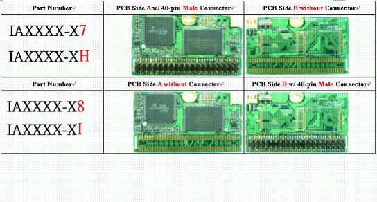
14 3.2 40/44-Pin Mini IDE Plain Form Pictures and Part Number 40-pin Mini IDE Plain Form 44-pin Mini IDE Plain Form Cheetah Pro Solution Supports Commercial Temperature 0 ~ +70 Supports Wide Temperature 20 ~ + 85 Mini IDE 40-pin Plain Form 44pin Plain Form Capacit W/ 4-pin Power Cable Support +5Vcc on-pin 20 Support Vcc power in 32MB/64MB/96MB /128MB/192MB/3GB IANXXX-C0 IANXXX-L0 IANXXX-CA IANXXX-LA IBNXXX-CA IBNXXX-LA pin Mini IDE L-Form Pictures and Part Number Switch for Master/Slave IANXXX-C1 (Standard Model) 1. PCB Side B 2. PCB Side A Power Socket White Line (indicates the Sid f Pi 1) Pin-1 Connected to Power Suppl Connect to Mini IDE Power Cable 14/ V4

15 Part Number PCB Side A w/ 40-pin Female Connector PCB Side B without Connecto IANXXX C/L/H1 P-1 Part Number PCB Side A witihout Connector PCB Side B w/ 40-pin Female Conn IANXXX C/L/H2 P-1 Part Number PCB Side A w/ 40-pin Female Connector PCB Side B w/ 40-pin Female Conn IANXXX C/L/H3 P-1 P-1 Part Number PCB Side A w/ 40-pin Female Connector PCB Side B w/ 40-pin Male Conne IANXXX C/L/H4 P-1 P-1 Part Number PCB Side A w/ 40-pin Male Connector PCB Side B 40-pin Female Conn IANXXX C/L/H5 P-1 P-1 Part Number PCB Side A w/ 40-pin Male Connector PCB Side B w/ 40-pin Male Conne 15/ V4
16 IANXXX C/L/H6 P-1 P-1 Part Number PCB Side A w/ 40-pin Male Connector PCB Side B without Connector IANXXX C/L/H7 P-1 Part Number PCB Side A without Connector PCB Side B w/ 40-pin Male Conne IANXXX C/L/H8 P-1 16/ V4
 6.")


17 pin Mini IDE L-Form Pictures and Part Number IBNXXX-CB (Standard Model) 6. Jumper for 4. PCB Side B 5. PCB Side A White Line 3. Ke-pin for Safet Plug-in Part Number PCB Side A w/ 40-pin Female Connector PCB Side B without Connector IBNXXX C/L/HB P-1 17/ V4

18 Part Number PCB Side A without Connector PCB Side B w/ 44-pin Feleale Conne IBNXXX C/L/HC P-1 Part Number PCB Side A with 44-pin Feleale Connector PCB Side B w/ 44-pin Female Conne IBNXXX C/L/HD P-1 P-1 Part Number PCB Side A w/ 44-pin Female Connector PCB Side B w/ 44-pin Male Connec IBNXXX C/L/HE P-1 P-1 Part Number PCB Side A w/ 44-pin Male Connector PCB Side B w/ 44-pin Female Conne IBNXXX C/L/HF P-1 P-1 18/ V4

19 Part Number PCB Side w/ 44-pin Male Connector PCB Side B w/ 44-pin Male Conne IBNXXX C/L/HG P-1 P-1 Part Number PCB Side w/ 44-pin Male Connector PCB Side B without Connecto IBNXXX C/L/HH P-1 Part Number PCB Side A without Connector PCB Side B w/ 40-pin Male Conne IBNXXX C/L/HI P-1 Cheetah Pro Solution Supports Commercial Temperature 0 ~ +70 Supports Wide Temperature -20 ~ + 85 Mini IDE 40-pin L-form 44-pin L-form Connector Tpe W/ 4-pin Power Cable Support +5Vcc on-pin 20 Support Vcc power IANXXX-C1 IANXXX-L1 IANXXX-H1 IANXXX-CB IANXXX-LB IANXXX-HB IBNXXX-CB IBNXXX-LB IBNXXX-HB IANXXX-C2 IANXXX-CC IBNXXX-CC IANXXX-L2 IANXXX-LC IBNXXX-LC IANXXX-H2 IANXXX-HC IBNXXX-HC IANXXX-C3 IANXXX-CD IBNXXX-CD IANXXX-L3 IANXXX-LD IBNXXX-LD IANXXX-H3 IANXXX-HD IBNXXX-HD 19/ V4
20 IANXXX-C4 IANXXX-L4 IANXXX-H4 IANXXX-CE IANXXX-LE IANXXX-HE IBNXXX-CE IBNXXX-LE IBNXXX-HE IANXXX-C5 IANXXX-CF IBNXXX-CF IANXXX-L5 IANXXX-LF IBNXXX-LF IANXXX-H5 IANXXX-HF IBNXXX-HF IANXXX-C6 IANXXX-CG IBNXXX-CG IANXXX-L6 IANXXX-LG IBNXXX-LG IANXXX-H6 IANXXX-HG IBNXXX-HG IANXXX-C7 IANXXX-CH IBNXXX-CH IANXXX-L7 IANXXX-LH IBNXXX-LH IANXXX-H7 IANXXX-HH IBNXXX-HH IANXXX-C8 IANXXX-CI IBNXXX-CI IANXXX-L8 IANXXX-LI IBNXXX-LI IANXXX-H8 IANXXX-HI IBNXXX-HI 20/ V4
21 4. Support Flash Media 4.1 Supported NAND Flash Tpe Small block size of 16KB Unit: bits Flash Capacit 128 Mega 256 Mega 512 Mega Operation Voltage 2.7V to 3.6V Large block size of 128KB Flash Capacit 1 Giga 2 Giga 3 Giga Operation Voltage 2.7V to 3.6V Unit: bits 4.2 Logical Format Parameters (CHS) Card Capacit *1 Unit: Btes Card Densit *4 32M 64M 128M 256M 512M Clinder Heads Sectors/Track * Total 62, , ,008 Sectors/Card *3 506,016 1,015,056 Capacit *5 31,248 63, , ,046, ,708,672 Card Densit *4 1GB 2GB 3GB Clinder Heads Sectors/Track * Total Sectors/Card *3 2,031,120 4,062,240 6,094,368 Capacit *5 1,039,933,440 2,079,866,880 3,120,316,416 Unit: Btes 21/ V4
22 1. These data are written in Identif table. 2. Total tracks =number of head x number of clinder. 3. Total sector/card = sector/track x number of head x number of clinder 4. Those are general unformatted capacit of all cards. 5. It s the logical address capacit including the area which is used for file sstem. 22/ V4
23 5. Block Diagram 5.1 Controller Archive Reset Frequenc Provider Power on Color Control x51 Turbo base Micro processor IDE Interface Host Interface CIS CCR Task Data transfer Control Data buffer ECC Logic Flash Memor Interface Control/ Status NAND Tpe Flash Memor CIS: Card Information Structure CCR: Card Configuration Register ECC: Error Correcting Code 5.2 Flash Card Archive Power IC Reset IC According Card Capacit From Range 25MHz ~ 38MHz Host Interface Controller Flash Memor 23/ V4
24 6. Specification and Features 6.1 Electrical Specification Absolute Maximum Ratings SYMBOL PARAMETER RATING UNITS V CC Power suppl -0.3 to 6 V V IN Input voltage -0.3 to V CC V V OUT Output voltage -0.3 to V CC V T STG Storage temperature -50 to 90 Topr Operating temperature -40 to General DC Characteristic SYMBOL PARAMETER CONDITIONS MIN TYP MAX UNITS C IN Input capacitance 15 pf C OUT Output capacitance 15 pf DC Electrical Characteristics for 5 Volts Operation SYMBOL PARAMETER CONDITIONS MIN TYP MAX UNITS V IN Input voltage 0 V CC V V CC Power suppl V T STG Storage temperature T OPR Operating temperature V IL Input low voltage CMOS 0.8 V V IH Input high voltage CMOS 2.4 V V OL Output low voltage I OL =8mA 0.4 V V OH Output high voltage I OH =-8mA V CC 0.8 V 24/ V4
25 6.1.4 DC Electrical Characteristics for 3.3 Volts Operation SYMBOL PARAMETER CONDITIONS MIN TYP MAX UNITS V IN Input voltage 0 V CC V V DD Power suppl V T STG Storage temperature T OPR Operating temperature V IL Input low voltage CMOS 0.6 V V IH Input high voltage CMOS 2.4 V V OL Output low voltage I OL =8mA 0.4 V V OH Output high voltage I OH =-8mA V DD 0.8 V True IDE Mode I/O (Read/Write) Timing Specification True IDE Mode I/O Mode 0 Mode 1 Mode 2 Mode 3 Mode 4 (Read/Write Timing item (ns) (ns) (ns) (ns) (ns) Specification) t 0 Ccle time (min) t1 Address Valid to -IORD/-IOWR setup (min) t2 -IORD/-IOWR (min) t 2 -IORD/-IOWR (min) Register (8 bit) t 2i -IORD/-IOWR recover time (min) t3 -IOWR data setup (min) t4 -IOWR data hold (min) t5 -IORD data setup (min) t6 -IORD data hold (min) t6z -IORD data tristate (max) t7 Address valid to -IOCS16 assertion (max) n/a n/a t8 Address valid to -IOCS16 released (max) n/a n/a t9 -IORD/-IOWR to address valid hold trd Read Data Valid to IORDY active 0 (min), if IORDY initiall low after ta ta ta IORDY Setup time tb IORDY Pulse Width (max) / V4
26 6.1.6 True IDE Ultra DMA Mode I/O (Read/Write) Timing Specification UDMA UDMA UDMA UDMA UDMA Name Mode 0 (ns) Mode 1 (ns) Mode 2 (ns) Mode 3 (ns) Mode 4 (ns) Min Max Min Max Min Max Min Max Min Max t2cyctyp CYC t2cyc tds tdh tdvs tdvh tcs tch tcvs tcvh tzfs tdzfs tfs / V4
27 Name UDMA UDMA UDMA UDMA UDMA Mode 0 (ns) Mode 1 (ns) Mode 2 (ns) Mode 3 (ns) Mode 4 (ns) tli tmli tui taz tzah tzad tenv trfs trp tiordyz tziordy tack tss Ultra DMA Data-In Burst Initiation Timing 27/ V4
28 Sustained Ultra DMA Data-In Burst Timing Ultra DMA Data-In Burst Host Pause Timing 28/ V4
29 Ultra DMA Data-In Burst Device Termination Timing Ultra DMA Data-In Burst Host Termination Timing 29/ V4
30 Ultra DMA Data-In Burst Host Termination Timing Sustained Ultra DMA Data-Out Burst Timing 30/ V4
31 Ultra DMA Data-Out Burst Device Pause Timing Ultra DMA Data-Out Burst Device Termination Timing 31/ V4
32 Ultra DMA Data-Out Burst Host Termination Timing 6.2 Power Management Normal Mode The host can reduce the power consumption of the card b changing its status with the following Power Command. Sleep mode consumes the lowest power. Response time for the card to change from sleep mode to the active state is about 30 ms or less. Standb mode, the response time is about 5ms or less. This is due to the interface of the card that accepts the command although can't access the media immediatel Idle mode, the card can respond and access the media immediatel. The card needs longer time in this mode than in its active mode in order to active several circuits that were not used in the active mode. Active mode, the card can respond and access the media immediatel, and the commands are processed with no dela Power down Mode This card can set itself into Power Down mode. To enable this mode, it is needed to use the Information Change command, which is a vender unique command. The advantage of using this mode is the abilit to move automaticall into Sleep mode after command completion. 32/ V4
33 6.3 Phsical Specification MIDE 40 pin P-form with housing outline dimensions Product Shaping 33/ V4
34 6.3.2 MIDE 40 pin L-form without housing outline dimensions Product Shaping 34/ V4
35 6.3.3 MIDE 44-pin P-form with housing outline dimension 35/ V4
36 6.3.4 MIDE 44-pin L-form without housing outline dimensions 36/ V4
37 7. Pin Assignment 7.1 Pin Tpe Pin Num. Pin Smbol Pin Tpe Pin Num. Pin Smbol Pin Tpe 1 #Reset I 2 GND Ground 3 Data 7 I/O 4 Data 8 I/O 5 Data 6 I/O 6 Data 9 I/O 7 Data 5 I/O 8 Data 10 I/O 9 Data 4 I/O 10 Data 11 I/O 11 Data 3 I/O 12 Data 12 I/O 13 Data 2 I/O 14 Data 13 I/O 15 Data 1 I/O 16 Data 14 I/O 17 Data 0 I/O 18 Data 15 I/O 19 GND Ground 20 Ke Cut Pin 21 DMARQ O 22 GND Ground 23 #IOW I 24 GND Ground 25 #IOR I 26 GND Ground 27 IORDY I 28 CSEL I 29 DMACK I 30 GND Ground 31 IRQ O 32 #IOCS16 O 33 A1 I 34 #PDIAG I/O 35 A0 I 36 A2 I 37 #CS0 I 38 #CS1 I 39 #DASP I/O 40 GND Ground 41 Vcc Suppl Voltage 42 Vcc Suppl Voltage 43 GND Ground 44 TYPE Note1: # means low active. Note2: Pin 41 to 44 NC for 40-pin product. 37/ V4
38 7.2 Interface Signals Description Signal Name Pin I/O Description #RESET 1 I HOST RESET Reset signal from the host that is active on power up and in thereafter. Data (15-0) 3-18 I/O HOST DATA15-0 These 16 lines carr the Data between the controller and the host. Th 8 lines transfer commands, status, and ECC information between th and the controller. DMARQ 21 O DMA REQUEST When read to transfer data to or from the host, this signal used for D data transfers between host and device, shall be asserted b the devic #IOW 23 I I/O WRITE This strobe pulse is used to clock data or commands on the host dat into the controller. The clocking will occur on the negative to po edge of the signal (trailing edge). #IOR 25 I I/O READ This is a read strobe generated b the host. This signal gates data or on the host bus and strobes the data from the controller into the host o low to high transition (trailing edge). IORDY 27 I I/O READY This signal is negated to extend the host transfer ccle of an host re access (Read or Write) when the device is not read to respond to a transfer request. Vcc 41, V Power suppl 38/ V4
39 Signal Name Pin I/O Description CSEL 28 I CABLE SELECT When grounded, the device is configured as a Master. When opened device is configured as a Slave. DMACK 29 I DMA ACKNOWLEDGE This signal shall respond to DMARQ b the host to initiate D transfers. IRQ 31 O INTERRUPT REQUEST This is an interrupt request from the controller to the host, askin service. The output of this signal is tri-stated when the interrup disabled b the host. #IOCS16 32 O I/O SELECT 16 This open drain output is asserted low to indicate to the host the cu ccle is a 16-bit word data transfer. #PDIAG 34 I/O PASS DIAGNOSTIC After an Execute Diagnostic command to indicate to the master passed its diagnostics, this bi-directional open drain signal is assert the slave. A (2-0) 33,35,36 I HOST ADDRESS 2-0 These address lines are used to select the registers within the cont task file. #CS0 37 I HOST CHIP SELECT 0 A chip select signal used to select the controller task file. #CS1 38 I HOST CHIP SELECT 1 A chip select signal that is used to select the control and diagn register. #DASP 39 I/O DISK ACTIVE/SLAVE PRESENT This open drain output signal is asserted low an time the drive is a In a master/slave configuration, the slave uses it to inform the master present. NC 20 - These pins are reserved for the connector kes. 39/ V4
40 GND 2,19,22,24,26,3 0,40,43 -- GROUND 7.3 Installing The SSD Drive In a Two-Drive Configuration If Pin A and Pin B are jumped, the drive is in Cable Select mode. If both pins A and B remain open, the SSD drive is configured as a Master in a Master/Slave configuration or as the onl drive in a single drive sstem. Pins A and B are pulled-up input pins that are shorted together internall (Pins C and D are ground). If the SSD drive is installed as the second, or Slave, drive in a two-drive configuration, either pin AC or none of the pins should be grounded. These pins will configure the SSD drive as a Slave device. Master/Slave Configuration Pins Cable Select: Slave: C A C A D B D B If Pin A and Pin B are jumped, 43 the drive is in Cable Select C A Master: C A D B If all pins A, B, C, and D are open, or Pin A 40/ V4
41 and Pin C are jumped, the drive is in Slave mode D B If Pin C and Pin D are jumped, the drive is in Master mode 41/ V4
42 8. ATA Specific Register Definitions As we described the adapter provides several kinds of addressing modes, Memor mode, I/O mode, and True IDE. Below are described the procedures access for accessing each mode the Task File registers. 8.1 True IDE Mode True IDE Mode #CS0 #CS1 DA2 DA1 DA0 #IORD = 0 #IOWR = X X X Hi-Z Not Used X X Hi-Z Not Used X Hi-Z Not Used 0 0 X X X Invalid Invalid Alternate Status Device Control Device Address Not Used Data Data Error Feature Sector Count Sector Count Sector Number Sector Number Clinder Low Clinder Low Clinder High Clinder High Drive/Head Drive/Head Status Command 8.2 ATA Registers Data Register The Data register is a 16-bit register used to transfer data blocks between the ATA data buffer and the host. In addition, the Format Track command uses this register to transfer the sector-information. Setting this mode requires calling the Set Features command. bit-7 bit-6 bit-5 bit-4 bit-3 bit-2 bit-1 bit-0 D7 D6 D5 D4 D3 D2 D1 D0 bit-15 bit-14 bit-13 bit-12 bit-11 bit-10 bit-9 bit-8 D15 D14 D13 D12 D11 D10 D9 D8 42/ V4
43 8.2.2 Error Register The Error Register contains additional information about the source of an error. The information in the register is onl valid when an error is indicated in ERR-bit (bit-0 = 1) of the Status Register. This register is valid when the BSY bit in Status register and Alternate status register are set to 0 (Read). bit-7 bit-6 bit-5 bit-4 bit-3 bit-2 bit-1 bit-0 BBK UNC MC[0] IDNF MCR[0] ABRT T0NF[0] AMNF BBK Bad Block mark detected in the requested sector ID field - Not supported UNC Non-Correctable data error encountered MC[0] Removable media access abilit has changed - not supported (is 0) IDNF Requested sector ID-field Not Found MCR[0] ABRT T0NF[0] AMNF Media Change Request indicates that the removable-media drive's latch has changed, indicating that the user wishes to remove the media - not supported (is 0) Drive status error or Aborted invalid command Track 0 Not Found during a Recalibrate command - Not supported Address Mark Not Found after finding the correct ID field - Not supported Feature Register This register enables drive-specific features. See the Set Features or Get/Set Features command descriptions. bit-7 bit-6 bit-5 bit-4 bit-3 bit-2 bit-1 bit-0 Feature bte Sector Count Register The Sector Count Register contains the number of data sectors requested to be transferred during a read or write operation between the host and the adapter. A zero register value specifies 256 sectors. The command was successful if this register is zero at command completion. If the request is not completed, the register contains the number of sectors left to be transferred. 43/ V4
44 This register s initial values is 01H Some commands (e.g. Initialize Drive Parameters or Format Track) ma redefine the register s contents.) bit-7 bit-6 bit-5 bit-4 bit-3 bit-2 bit-1 bit-0 Sector count bte Sector Number Register In the CHS (Clinder, Head, Sector) mode, the Sector Number register contains the subsequent command's starting sector number, which can be from 1 to the maximum number of sectors per track. In LBA (logical block address) mode, this register contains LBA bits 0-7, which are updated at command completion. See the command descriptions for register contents at command completion (whether successful or unsuccessful). bit-7 bit-6 bit-5 bit-4 bit-3 bit-2 bit-1 bit-0 SN7 SN6 SN5 SN4 SN3 SN2 SN1 SN0 LBA7 LBA6 LBA5 LBA4 LBA3 LBA2 LBA1 LBA0 SN0 SN7 Sector number bte (8-bits) LBA0 LBA7 LBA bits 0 to 7 44/ V4
45 8.2.6 Clinder Low Register In the CHS mode, the Clinder Low Register contains the clinder number low-8 bits and reflects their status at command completion. In LBA mode, this register contains LBA bits 8-15 and reflects their status at command completion. bit-7 bit-6 bit-5 bit-4 bit-3 bit-2 bit-1 bit-0 CL7 CL6 CL5 CL4 CL3 CL2 CL1 CL0 LBA15 LBA14 LBA13 LBA12 LBA11 LBA10 LBA9 LBA8 CL0 CL7 Clinder Low bte (8-bits) LBA8 LBA15 LBA bits 8 to Clinder High Register In the CHS mode, the Clinder High Register contains the clinder numbers high-8 bits and reflects their status at command completion. In LBA mode, this register contains LBA bits and reflects their status at command completion. bit-7 bit-6 bit-5 bit-4 bit-3 bit-2 bit-1 bit-0 CH7 CH6 CH5 CH4 CH3 CH2 CH1 CH0 LBA23 LBA22 LBA21 LBA20 LBA19 LBA18 LBA17 LBA16 CH0 CH7 Clinder High bte (8-bits) LBA16 LBA23 LBA bits 16 to 23 45/ V4
46 8.2.8 Drive Head Register The Drive/Head Register is used to select the drive and head (heads minus 1, when executing Initialize Drive Parameters command). It is also used to select the LBA addressing instead of the CHS addressing. bit-7 bit-6 bit-5 bit-4 bit-3 bit-2 bit-1 bit-0 1 LBA 1 DRV HS3 HS2 HS1 HS0 HS0-HS3/ DRV LBA24-LBA27 LBA Head number. Drive select number. When DRV=0, the master drive is selected. When DRV=1, the Slave drive is selected. MSB of the LBA addressing. Address mode select. 0 = CHS (Clinder, Head, Sector) mode. 1 = LBA (Logical Block Address) mode. Logical Block address interrupted as follows: LBA07-LBA00 :Sector Number Register D7-D0 LBA15-LBA08:Clinder Low Register D7-D0 LBA23-LBA16:Clinder High Register D7-D0 LBA27-LBA24:Drive/Head Register HS3-HS0 46/ V4
47 8.2.9 Status Register This register contains the adapter status. The contents of this register are updated to reflect the current state of the adapter and the progress of an command being executed b the adapter. When the BSY bit is equal to zero, the other bits in this register are valid. When the BSY bit is equal to one, the other bits in this register are not valid. When the register is read, the interrupt (#IREQ pin) is cleared. bit-7 bit-6 bit-5 bit-4 bit-3 bit-2 bit-1 bit-0 BSY DRDY DWF DSC DRQ CORR 0 ERR ERR IDX CORR DRQ DSC DWF DRDY BSY When set, indicates that an error has occurred during the previous command execution. The bits in the Error Register indicate the cause. Index is not used alwas set to Zero. Indicates that a data error was corrected; transfer is not terminated. Data Request. When set, indicates that the adapter is read to transfer a word or bte of data between the host and the adapter. Drive Seek Complete. When set, indicates that the requested sector was found. Drive Write Fault status. When set, indicates that an error has occurred during write. Indicates whether the adapter is capable of performing drive operations (commands). This bit is cleared at power up and remains cleared until the drive is read to accept a command. On error, DRDY changes onl after the host reads the Status register. This signal is set during the time the adapter accesses the command buffer or the registers. During this time the host is locked out from accessing the command register and buffer. As long as this bit is set no bits in the register are valid Alternate Status Register The Alternate Status Register contains command block status information (see Status register). Unlike the Status register, reading this register does not acknowledge or clear an interrupt. bit-7 bit-6 bit-5 bit-4 bit-3 bit-2 bit-1 bit-0 BSY DRDY DWF DSC DRQ CORR 0 ERR 47/ V4
48 Device Control Register The Device Control Register is used to control the drive interrupt request and issue an ATA soft reset to the drive. bit-7 bit-6 bit-5 bit-4 bit-3 bit-2 bit-1 bit SRST #IEN 0 #IEN INTERRUPT ENABLE: When set (0), it enables interrupts to the host (using the #IREQ tri-state pin). When inactive (1) or drive is not selected, it disables all pending interrupts (#IREQ in high-z). This bit is ignored in Memor mode. SRST SOFT RESET: When set, forces the ATA to perform an AT disk control soft reset operation Drive Address Register This register reflects the drive and its heads. This register is provides for compatibilit with the AT disk interface. It s recommended that this register is not mapped into this host s I/O space because of potential conflicts on bit7. bit-7 bit-6 bit-5 bit-4 bit-3 bit-2 bit-1 bit-0 High-Z #WTG #HS3 #HS2 #HS1 #HS0 #DS1 #DS0 #DS0 #DS1 #HS0 - #HS3 #WTG When set (0), it indicates that drive 0 is active and selected. When set (0), it indicates that drive 1 is active and selected. Negation of the head number in the Drive/Head Register. When set (0), it indicates that a write operation is in progress, otherwise it is inactive (1) - not supported. Note: Addressing Mode Descriptions - The adapter, on a command b command basis, can operate in either CHS or LBA addressing modes. Identif Drive Information tells the host whether the drive supports LBA mode. The host selects LBA mode via the Drive/Head Register. Sector number, Clinder Low, Clinder High, and Drive/Head Register bits HS3=0 contain the zero-based LBA. The drive's sectors are linearl mapped with: LBA = 0 => Clinder 0, head 0, sector 1. Regardless of the translation mode, a sector LBA address does not change. LBA = (Clinder * no of heads + heads) * (sectors/track) + (Sector - 1). 48/ V4
49 9. ATA Commands 9.1 Check Power Mode - 98H or E5H This command checks the current power mode of the adapter. When this command is issued and the adapter is in standb mode, or is being set to standb mode, or during a recover from standb mode is attempted, adapter sets the BSY bit in the Status register and sets the Sector Count Register to 00H. Then the BSY bit in the Status register is cleared. When the adapter is in the Idle mode, it sets the BSY bit in the Status register and sets FFH in the Sector Count Register. Then the BSY bit in the Status register is cleared. An interrupt is issued after the BSY bit is cleared. INPUTS Features N/A Sector Count N/A Sector Number N/A Clinder Low N/A Clinder High N/A Command 98H or E5H OUTPUTS Status BSY DRDY DWF DSC DRQ CORR IDX ERR V V V V V V Sector Count Error Power Mode Code.(00H or 80H or FFH) BBK UNC MC IDNF MCR ABRT TK0NF AMNF V 49/ V4
50 9.2 Execute Drive Diagnostic - 90H This command performs self-diagnostics on various internal components of the adapter. Results of the test are reported in the Error Register. Note that the bit definitions for the Error Register do not appl with this command. Instead, the value in the Error Register is a diagnostic code, defined in the table below. INPUTS Features N/A Sector Count N/A Sector Number N/A Clinder Low N/A Clinder High N/A Device/Head DEV Command 90H OUTPUTS: The diagnostic code written into the Error Register is an 8-bit code as shown in the table below. BSY DRDY DWF DSC DRQ CORR IDX ERR Status V V V V Error Diagnostic code, see table below Code 01H 02H 03H 04H 05H Description No error detected Format Media error Sector buffer error ECC logic error Controlling microprocessor error 50/ V4
51 9.3 Erase Sector(s) - C0H This command is processed as a NOP command. INPUTS Features N/A Sector Count [LBA mode onl] The number of sectors to be formatted on the track, must be set to FFH Sector Number [LBA mode onl] LBA[7:0] of the first sector/lba to transfer Clinder Low Clinder[7:0] or LBA[15:8] of the first sector/lba to transfer Clinder High Clinder[15:8] or LBA[23:16] of the first sector/lba to transfer Device/Head LBA DEV H[3:0] or LBA[27:24] of the starting sector/lba Command C0H OUTPUTS Status BSY DRDY DWF DSC DRQ CORR IDX ERR V V V V V Error BBK UNC MC IDNF MCR ABRT TK0NF AMNF V V V V 51/ V4
52 9.4 Format Track - 50H This command is processed as a NOP command. INPUTS Features Sector Count [LBA mode onl] The number of sectors to be formatted on the track. Must be set to FFH Sector Number [LBA mode onl] LBA[7:0] of the first sector/lba to transfer Clinder Low Clinder[7:0] or LBA[15:8] of the first sector/lba to transfer Clinder High Clinder[15:8] or LBA[23:16] of the first sector/lba to transfer Device/Head LBA DEV H[3:0] or LBA[27:24] of the starting sector/lba Command 50H OUTPUTS Status BSY DRDY DWF DSC DRQ CORR IDX ERR V V V V V Error BBK UNC MC IDNF MCR ABRT TK0NF AMNF V V V 52/ V4
53 9.5 Identif Drive ECH The Identif Drive command enables the host to receive parameter information from the adapter. When the command is issued, the adapter sets the BSY bit, prepares to transfer the 256 words of adapter identification data to the host, sets the DRQ bit, clears the BSY bit, and generates an interrupt. The host can then transfer the data b reading the Data register. All reserved bits or words are all zero. See following table for the identif drive information for this adapter INPUTS Features N/A Sector Count N/A Sector Number N/A Clinder Low N/A Clinder High N/A Device/Head DEV Command ECH OUTPUTS BSY DRDY DWF DSC DRQ CORR IDX ERR Status V V V V V V BBK UNC MC IDNF MCR ABRT TK0NF AMNF Error V 53/ V4
54 9.6 Idle - 97H or E3H Although this command is supported for backward compatibilit, it has no actual function. The adapter will alwas return a good status at the completion of this command. INPUTS Features N/A Sector Count Time-out Parameter. This parameter is ignored b the adapter Sector Number N/A Clinder Low N/A Clinder High N/A Device/Head DEV Command 97H or E3H OUTPUTS Status BSY DRDY DWF DSC DRQ CORR IDX ERR V V V V V V Error BBK UNC MC IDNF MCR ABRT TK0NF AMNF V 54/ V4
55 9.7 Idle Immediate - 95H or E1H Although this command is supported for backward compatibilit, it has no actual function. The adapter will alwas return a good status at the completion of this command. INPUTS Features N/A Sector Count N/A Sector Number N/A Clinder Low N/A Clinder High N/A Device/Head DEV Command 95H or E1H OUTPUTS Status BSY DRDY DWF DSC DRQ CORR IDX ERR V V V V V V Error BBK UNC MC IDNF MCR ABRT TK0NF AMNF V 55/ V4
56 9.8 Initialize Drive Parameters - 91H Initialize Drive Parameters allows the host to alter the number of sectors per track and the number of heads per clinder. This command does not check the validit of counts of sectors and heads. If an invalid value is set, an error will be reported when another command attempts an invalid access. The Sector Count Register specifies the number of logical sectors per logical track, and the Device/Head register specifies the maximum head number. INPUTS Features N/A Sector Count Number of sectors Sector Number N/A Clinder Low N/A Clinder High N/A Device/Head DEV Max Head (no. of head = 1) Command 91H OUTPUTS Status BSY DRDY DWF DSC DRQ CORR IDX ERR V V V V V Error BBK UNC MC IDNF MCR ABRT TK0NF AMNF 56/ V4
57 9.9 Read Buffer - E4H The Read Buffer command enables the host to read the current contents of the adapter s sector buffer. This command has the same protocol as the Read Sector(s) command. INPUTS Features N/A Sector Count N/A Sector Number N/A Clinder Low N/A Clinder High N/A Device/Head LBA DEV Command E4H OUTPUTS Status BSY DRDY DWF DSC DRQ CORR IDX ERR V V V V V V Error BBK UNC MC IDNF MCR ABRT TK0NF AMNF V 57/ V4
58 9.10 Read Long Sector(s) - 22H or 23H Read Long (w/ and w/o retr) is similar to the Read Sectors command, except that the content of the Sector Count Register is ignored and onl one sector is read. The 512 data btes and 4 ECC btes are read into the buffer (with no ECC correction) and then transferred to the host. The Clinder Low, Clinder High, Device/Head and Sector Number specif the starting sector address to be read. The Sector Count Register shouldn t specif a value other than 1. INPUTS Features N/A Sector Count The number of sectors/logical blocks to transfer. This should be set to 01 for compatibilit Sector Number Sector[7:0] or LBA[7:0] of the sector/lba to transfer Clinder Low Clinder[7:0] or LBA[15:8] of the sector/lba to transfer Clinder High Clinder[15:8] or LBA[23:16] of the sector/lba to transfer Device/Head LBA DEV H[3:0] or LBA[27:24] of the sector/lba to transfer Command 22H (retries enabled) or 23H (retries disabled) OUTPUTS BSY DRDY DWF DSC DRQ CORR IDX ERR Status V V V V V V Sector Count Sector Number Clinder Low Clinder High Error 00 if the command proceed without error, else the number of untransfered sectors. Sector[7:0] or LBA[7:0] of the last sector read Clinder[7:0] or LBA[15:8] of the last sector read Clinder[15:8] or LBA[23:16] of the last sector read BBK UNC MC IDNF MCR ABRT TK0NF AMNF V V V V 58/ V4
59 9.11 Read Multiple - C4H This command functions like the Read Sector(s) command, but instead of issuing interrupts for each sector, interrupts are issued when a block containing the counts of sectors, defined b the Set Multiple command is, transferred. Also, the DRQ required for the transfer onl has to be set at the start of the data block and does not affect other sectors. When the Read Multiple command is issued, the requested sectors (not the block counts or the sector counts in a block) are written into the Sector Count Register. Errors occurring during command execution are reported at the start of a block transfer or at the start of transfer of part of a block. However, the transfer continues even if DRQ is set and the data is corrupted. After the data transfer, the content of the task file with the block data containing the sectors where the error occurred is not defined. To obtain valid error information the host has to request a re-transmission. The next block or part of a block is transferred onl if the error is correctable. For all other errors the command is aborted after transferring a block containing an error. The Read Multiple command is supported for backward compatibilit. If R/W Multiple commands have been enabled b a previous valid Set Multiple command, the Read Multiple command is identical to the Read Sectors operation except that several sectors are transferred as a block to the Host without the intervening Host handshaking. The block count stands for the number of sectors to be transferred as a block. It is established using the Set Multiple command. Although the Set Multiple, and R/W Multiple commands are supported, the onl valid block count is one. INPUTS Features N/A Sector Count The number of sectors/logical blocks to transfer Sector Number Sector[7:0] or LBA[7:0] of the sector/lba to transfer Clinder Low Clinder High Clinder[7:0] or LBA[15:8] of the sector/lba to transfer Clinder[15:8] or LBA[23:16] of the sector/lba to transfer Device/Head LBA DEV Head number or LBA Command OUTPUTS C4H BSY DRDY DWF DSC DRQ CORR IDX ERR Status V V V V V V V Sector Count Sector Number Clinder Low Clinder High The first sector where the first unrecoverable error occurred Sector[7:0] or LBA[7:0] of the last good sector transferred Clinder[7:0] or LBA[15:8] of the last good sector transferred Clinder[15:8] or LBA[23:16] of the last good sector transferred Device/Head LBA DEV H[3:0] or LBA[27:24] last good sector transferred Error BBK UNC MC IDNF MCR ABRT TK0NF AMNF 59/ V4
60 9.12 Read Sectors(s) 20H or 21H V V V V V V V V The Clinder Low, Clinder High, Device/Head and Sector Number or LBA registers specif the starting sector address to be read. The Sector Count Register specifies the number of sectors to be transferred. INPUTS Features N/A Sector Count The number of sectors/logical blocks to transfer Sector Number Sector[7:0] or LBA[7:0] of the sector/lba to transfer Clinder Low Clinder[7:0] or LBA[15:8] of the sector/lba to transfer Clinder High Clinder[15:8] or LBA[23:16] of the sector/lba to transfer Device/Head LBA DEV H[3:0] or LBA[27:24] of the sector/lba to transfer Command 20H (retr enabled) or 21H (retries disabled) OUTPUTS BSY DRDY DWF DSC DRQ CORR IDX ERR Status V V V V V V V Sector Count Sector Number Clinder Low Clinder High The first sector where the first unrecoverable error occurred Sector[7:0] or LBA[7:0] of the last good sector transferred Clinder[7:0] or LBA[15:8] of the last good sector transferred Clinder[15:8] or LBA[23:16] of the last good sector transferred Device/Head LBA DEV H[3:0] or LBA[27:24] last good sector transferred Error BBK UNC MC IDNF MCR ABRT TK0NF AMNF V V V V V V V 60/ V4
61 9.13 Read Verif Sector(s) 40H or 41H The Read Verif Sectors command verifies one or more sectors on the card b transferring data from the Flash media to the data buffer in the card and verifing that the ECC is correct. It is performed identicall to the Read Sectors command, except that DRQ is not asserted, and no data is transferred to the host. If an uncorrectable error occurs, the Read Verif command will be terminated at the failing sector. The task file registers contain the CHS, or LBA of the sector in which the error occurred. The Clinder Low, Clinder High, Device/Head and Sector Number specif the starting sector address to be verified. The Sector Count Register specifies the number of sectors to be verified. INPUTS Features N/A Sector Count The number of sectors/logical blocks to verif Sector Number Sector[7:0] or LBA[7:0] of the first sector/lba to verif Clinder Low Clinder[7:0] or LBA[15:8] of the sector/lba to verif Clinder High Clinder[15:8] or LBA[23:16] of the first sector/lba to verif Device/Head LBA DEV H[3:0] or LBA[27:24] of the sector/lba to verif Command 40H (retries enabled) or 41H (retries disabled) OUTPUTS BSY DRDY DWF DSC DRQ CORR IDX ERR Status V V V V V V V Sector Count Sector Number Clinder Low Clinder High The first sector where the first unrecoverable error occurred Sector[7:0] or LBA[7:0] of the sector/lba to transfer Clinder[7:0] or LBA[15:8] of the sector/lba to transfer Clinder[15:8] or LBA[23:16] of the last good sector transferred Device/Head LBA DEV H[3:0] or LBA[27:24] of the sector/lba to transfer Error BBK UNC MC IDNF MCR ABRT TK0NF AMNF V V V V V V V 61/ V4
62 9.14 Recalibrate - 1XH The adapter performs onl the interface timing and register operations. When this command is issued, the adapter sets BSY and waits for an appropriate length of time after which it clears BSY and issues an interrupt. When this command ends normall, the adapter is initialized. INPUTS Features N/A Sector Count N/A Sector Number N/A Clinder Low N/A Clinder High N/A Device/Head DEV Command 1XH OUTPUTS Status BSY DRDY DWF DSC DRQ CORR IDX ERR V V V V Error BBK UNC MC IDNF MCR ABRT TK0NF AMNF V 62/ V4
63 9.15 Request Sense - 03H This command requests extended error information for the previous command. The table below defines the valid extended error codes. Those codes are placed in the Error Register. INPUTS Features N/A Sector Count N/A Sector Number N/A Clinder Low N/A Clinder High N/A Device/Head DEV Command 03H OUTPUTS The diagnostic code written into the Error Register is an 8-bit code as shown in the table below. BSY DRDY DWF DSC DRQ CORR IDX ERR Status V V V V Error Sense code, see table below Code Description 00H No error detected 01H Self test OK (No error) 03H Write/Erase failed 09H Miscellaneous Error - N/A 20H Invalid Command 21H Invalid Address (requested Head or Sector invalid) 2FH Address Overflow (address too large) 35H, 36H Suppl or generate Voltage Out of Tolerance 11H Uncorrectable ECC Error 18H Corrected ECC Error - N/A 05H, 30H-34H, 37H, 3EH Self Test Diagnostic Failed 10H, 14H ID Not Found - N/A 3AH Spare Sectors Exhausted 1FH Data Transfer Error / Aborted Command 0CH, 38H, 3BH, 3CH, 3FH Corrupted Media Format - N/A 63/ V4
64 9.16 Seek - 7XH This command seeks and picks up the head to track specified in the Task File registers. Actuall the adapter performs onl an interface timing and register information. INPUTS Features N/A Sector Count N/A Sector Number (Valid in LBA mode onl) LBA[7:0] of the track Clinder Low Clinder[7:0] or LBA[15:8] of the track Clinder High Clinder[15:8] or LBA[23:16] of the track Device/Head LBA DEV H[3:0] or LBA[27:24] of the track Command 7XH OUTPUTS Status BSY DRDY DWF DSC DRQ CORR IDX ERR V V V V V V Error BBK UNC MC IDNF MCR ABRT TK0NF AMNF V V V V 64/ V4
65 9.17 Set Feature - EFH This command is used b the host to establish or select from the specific features listed below.(after a power up or a hardware reset) An ATA software reset does not set the features to default. The feature code is set to 81H, this mode is the default mode. INPUTS Features Feature number according to the table below Sector Count Configuration required Sector Number N/A Clinder Low N/A Clinder High N/A Device/Head DEV Command EFH Feature Codes Code 01H 55H 66H 81H BBH CCH Description Enable 8-bit data transfers Disable Read Look Ahead Disable reverting to power on defaults Disable 8-bit data transfers 4 btes of ECC appl on read long/write long commands Enable reverting to power on defaults OUTPUTS Status BSY DRDY DWF DSC DRQ CORR IDX ERR V V V V V V Error BBK UNC MC IDNF MCR ABRT TK0NF AMNF V 65/ V4
66 9.18 Set Multiple Mode - C6H The Set Multiple command allows the adapter to perform Read Multiple and Write Multiple operations. It also sets the block count (counts of sectors making up a block) for these commands. The sector count per block is placed is the Sector Count Register. The adapter supports onl blocks with one sector. INPUTS Features N/A Sector Count Sector Count per Block( = 1) Sector Number N/A Clinder Low N/A Clinder High N/A Device/Head DEV Command C6H OUTPUTS Status BSY DRDY DWF DSC DRQ CORR IDX ERR V V V V V V Error BBK UNC MC IDNF MCR ABRT TK0NF AMNF V 66/ V4
67 9.19 Set Sleep Mode - 99H or E6H This is the onl command that allows the host to set the adapter into Sleep mode. When the adapter is set to sleep mode, the adapter clears the BSY line and issues an interrupt. The adapter enters sleep mode and the onl method to make the adapter active again (back to normal operation) is b performing a hardware reset or software reset. INPUTS Features N/A Sector Count N/A Sector Number N/A Clinder Low N/A Clinder High N/A Device/Head DEV Command 99H/E6H OUTPUTS Status BSY DRDY DWF DSC DRQ CORR IDX ERR V V V V V V Error BBK UNC MC IDNF MCR ABRT TK0NF AMNF V 67/ V4
68 9.20 Standb - 96H or E2H This command is sets the adapter in Standb mode. If the Sector Count Register is a value other than 0H, an Auto Power Down is enabled and when the adapter returns to the idle mode, the timer starts a countdown. The time is set in the Sector Count Register. INPUTS Features N/A Sector Count Time period value Sector Number N/A Clinder Low N/A Clinder High N/A Device/Head DEV Command 96H or E2H OUTPUTS Status BSY DRDY DWF DSC DRQ CORR IDX ERR V V V V V V Error BBK UNC MC IDNF MCR ABRT TK0NF AMNF V 68/ V4
69 9.21 Standb Immediate 94H or E0H This command sets the adapter into standb mode. INPUTS Features N/A Sector Count N/A Sector Number N/A Clinder Low N/A Clinder High N/A Device/Head DEV Command 94H or E0H OUTPUTS Status BSY DRDY DWF DSC DRQ CORR IDX ERR V V V V V V Error BBK UNC MC IDNF MCR ABRT TK0NF AMNF V 69/ V4
70 9.22 Translate Sector - 87H This command allows the host a method of determining the exact number of times a sector was used (erased). The controller responds with the 512-bte buffer of information that includes the Hot Count, if available, for the sector. This command is not supported in this adapter and will alwas return the Hot Count as 00. INPUTS Features N/A Sector Count Sector Count Sector Number Sector[7:0] or LBA[7:0] of the first sector/lba to transfer Clinder Low Clinder[7:0] or LBA[15:8] of the first sector/lba to transfer Clinder High Clinder[15:8] or LBA[23:16] of the first sector/lba to transfer Device/Head LBA DEV H[3:0] or LBA[27:24] of the starting sector/lba Command 87H OUTPUTS The diagnostic code written into the Error Register is an 8-bit code as shown in the table below. BSY DRDY DWF DSC DRQ CORR IDX ERR Status V V V V V Error BBK UNC MC IDNF MCR ABRT TK0NF AMNF V V V Address 00H - 01H 02H 03H 04H - 06H 07H - 12H 13H 14H - 17H 18H - 1AH 1BH - 1FFH Information Clinder MSB (00H), Clinder LSB (01H) Head Sector LBA MSB (04H) - LSB (06H) Reserved Erased Flag (FFH) = Erased; (00H) = Not Erased Reserved Hot Count MSB (18H) - LSB (1AH) Reserved 70/ V4
Tiger ATA Industrial Application
 Preliminary Tiger ATA Industrial Application Product Specification December 2008 1/18 Document History Version Description Date Editor Approved by 1.0 New issue December 2008 Amos Chung Matika This document
SLFDMpqr-xxx(M/G)M1U(I)
M1U(I)") 128MB to 8GB www.simpletech.com ATA-5 Compatible Supports True-IDE Interfaces Capacities from 128MB to 8GB Form Factors: 40-Pin and Vertical Plug-In 40-Pin and Horizontal Plug-In 40-Pin, Vertical Plug-In,
128MB to 8GB www.simpletech.com ATA-5 Compatible Supports True-IDE Interfaces Capacities from 128MB to 8GB Form Factors: 40-Pin and Vertical Plug-In 40-Pin and Horizontal Plug-In 40-Pin, Vertical Plug-In,
CompactFlash TM Disk INDUSTRIAL GRADE W7CFxxxA-H Series
 CompactFlash TM Disk INDUSTRIAL GRADE W7CFxxxA-H Series INFORMATION IN THIS DOCUMENT IS PROVIDED IN RELATION TO WINTEC INDUSTRIES PRODUCTS, AND IS SUBJECT TO CHANGE WITHOUT NOTICE. NOTHING IN THIS DOCUMENT
CompactFlash Card W7CFxxxA-H2
 CompactFlash Card H2 Series W7CFxxxA-H2 INFORMATION IN THIS DOCUMENT IS PROVIDED IN RELATION TO WINTEC INDUSTRIES PRODUCTS, AND IS SUBJECT TO CHANGE WITHOUT NOTICE. NOTHING IN THIS DOCUMENT SHALL BE CONSTRUED
DiskOnChip IDE Pro. Flash Disk with IDE Interface. Highlights. Operating Temperature. Environmental Conditions. IDE Modes.
 Data Sheet DiskOnChip IDE Pro Flash Disk with IDE Interface Highlights DiskOnChip IDE Pro is a flash disk with an IDE interface. It combines advanced and proven DiskOnChip technology with a standard IDE
64 MB 2.5-Inch IDE Flash Drive GENERAL DESCRIPTION FEATURES ORDERING INFORMATION. IDE Flash Drives
 64 MB 2.5-Inch IDE Flash Drive GENERAL DESCRIPTION The SimpleTech SLFLD25-064J(U)(I) is a solid-state flash IDE drive with a capacity of 64MB and in a standard 2.5- inch form factor. The IDE drive consists
SLFLD25-xxxJ(I) 128 MB to 8 GB 2.5-Inch IDE Flash Drives GENERAL DESCRIPTION FEATURES ORDERING INFORMATION. IDE Flash Drives
 128 MB to 8 GB 2.5-Inch IDE Flash Drives GENERAL DESCRIPTION FEATURES ORDERING INFORMATION. IDE Flash Drives") 128 MB to 8 GB 2.5-Inch IDE Flash Drives GENERAL DESCRIPTION The SimpleTech SLFLD25-xxxJ(I) are solid-state flash IDE drives with capacities of 128MB to 8GB and in a standard 2.5- inch form factor. The
128 MB to 8 GB 2.5-Inch IDE Flash Drives GENERAL DESCRIPTION The SimpleTech SLFLD25-xxxJ(I) are solid-state flash IDE drives with capacities of 128MB to 8GB and in a standard 2.5- inch form factor. The
Features. Dimensions
 Description The Transcend CF 266X is a High Speed Compact Flash Card with high quality Flash Memory assembled on a printed circuit board. Placement Features CompactFlash Specification Version 4.0 Complaint
FMJ ES PC Card FEATURES
 FEATURES Capacity range: 128MB to 32GB Industry standard Type II PC Card form factor Integrated wear-leveling and ECC technology OVERVIEW The is a small, low cost, high performance, removable solidstate
Embedded Disk Card 4000 Datasheet. InnoDisk EDC4000. Embedded Disk Card Datasheet. Ver 1.1
 InnoDisk EDC4000 Embedded Disk Card 4000 Datasheet Ver 1.1 1 Ver 1.1 Datasheet, April 2008 Table of contents 1. PRODUCT OVERVIEW...6 1.1 INTRODUCTION TO EMBEDDED DISK CARD 4000...6 1.2 PRODUCT MODELS...6
EmbedDisk IDM. Datasheet
 EmbedDisk IDM Datasheet Ver 1.1 1 DMP Electronics Inc. Table of contents 1. PRODUCT OVERVIEW...6 1.1 INTRODUCTION TO EMBEDDED DISK CARD...6 1.2 PRODUCT MODELS...6 1.3 PIN ASSIGNMENT...6 1.4 PIN DESCRIPTION...7
Cervoz Industrial Embedded Module
 Cervoz Industrial Embedded Module PATA Disk 40pin Vertical Supreme Series (SLC) S130 Family Product Datasheet Date: 2015.04.13 Revision: 1.1 File: Revision History Date Revision Description 2015.02.02
Features. Dimensions
 Description The Transcend CF 133X is a High Speed Compact Flash Card with high quality Flash Memory assembled on a printed circuit board. Placement Features CompactFlash Specification Version 4.1 Complaint
Embedded Disk Card 2000Plus (EDC2000+) InnoDisk EDC2000+ Embedded Disk Card 2000Plus. Datasheet. Rev 1.4
 InnoDisk EDC2000+ Embedded Disk Card 2000Plus. Datasheet. Rev 1.4") InnoDisk EDC2000+ Embedded Disk Card 2000Plus Datasheet Rev 1.4 1 Rev. 1.4 Datasheet, July 2007 Table of contents REVISION HISTORY...4 LIST OF TABLES...5 LIST OF FIGURES...6 1. PRODUCT OVERVIEW...7 1.1
InnoDisk EDC2000+ Embedded Disk Card 2000Plus Datasheet Rev 1.4 1 Rev. 1.4 Datasheet, July 2007 Table of contents REVISION HISTORY...4 LIST OF TABLES...5 LIST OF FIGURES...6 1. PRODUCT OVERVIEW...7 1.1
EmbedDisk DDOM-SST Datasheet
 EmbedDisk DDOM-SST Datasheet Version 2.0 Aug. 2008 1 DMP Electronics Inc. A. Product Information Dependable and secure Designed with advanced IDE flash controller technology, EmbedDisk is 100% compatible
California PC FLASH ATA PC Card PCMCIA Full Specifications
 CaliforniaPC.com California Peripherals & Components, Inc. WorldWide Supplier of Computer Hardware & Software Any Where. Any Temperature.* California PC FLASH ATA PCMCIA Full Specifications Industrial
IEI EDC2000+ IFM-4000/4400 series
 IEI EDC2000+ IFM-4000/4400 series Embedded Disk Card 2000Plus Datasheet Rev 1.0 1 Rev. 1.0 Datasheet, November 2006 Table of contents REVISION HISTORY...4 LIST OF TABLES...5 LIST OF FIGURES...6 1. PRODUCT
Cervoz Industrial SSD
 Cervoz Industrial SSD 2.5 PATA Momentum Series (MLC) M120 Family Product Datasheet Date: 2015.01.05 Revision: 1.0 Revision History Date Revision Description 2015.01.05 1.0 First Released Table of Contents
Cervoz Industrial Embedded Module
 Cervoz Industrial Embedded Module PATA Disk 44pin Horizontal Left Supreme Series (SLC) S130 Family Product Datasheet Revision History Date Revision Description 2015.05.15 1.0 First Released Table of Contents
FiD Flash in Disk (FiD) ATA4000. InnoDisk FiD ATA4000. Flash in Disk ATA4000. Datasheet. Rev. 1.1
 ATA4000. InnoDisk FiD ATA4000. Flash in Disk ATA4000. Datasheet. Rev. 1.1") InnoDisk FiD ATA4000 Flash in Disk ATA4000 Datasheet Rev. 1.1 1 Rev. 1.0 Data Sheet, January 2006 Table of contents REVISION HISTORY... 3 LIST OF TABLES... 4 LIST OF FIGURES... 5 1. PRODUCT OVERVIEW...
InnoDisk FiD ATA4000 Flash in Disk ATA4000 Datasheet Rev. 1.1 1 Rev. 1.0 Data Sheet, January 2006 Table of contents REVISION HISTORY... 3 LIST OF TABLES... 4 LIST OF FIGURES... 5 1. PRODUCT OVERVIEW...
Standard. Customer Approver. Innodisk Approver. Customer: Customer Part Number: Innodisk Part Number: Innodisk Model Name: Date:
 Standard Customer: Customer Part Number: Innodisk Part Number: Innodisk Model me: Date: Innodisk Approver Customer Approver Table of contents 1. INTRODUCTION... 9 2. FEATURES... 9 3. PIN ASSIGNMENT...
Features. Description. Placement. Dimensions. Transcend Information Inc.
 Description The Transcend CF200I is a High Speed industrial Compact Flash Card with high quality Flash Memory assembled on a printed circuit board. Placement Features CompactFlash Specification Version
InnoDisk icf8000. Industrial CompactFlash Card Datasheet. Datasheet. AmpliconBenelux.com. Rev IT and Instrumentation for Industry
 InnoDisk icf8000 Industrial CompactFlash Card 8000 Datasheet Rev. 1.3 1 Rev. 1.3 Datasheet, Dec. 2009 Table of contents 1. INTRODUCTION... 9 2. FEATURES... 9 3. PIN ASSIGNMENT... 11 4. PIN DESCRIPTION...
C670 Series. Ultra High Performance CompactFlash. Engineering Specification. Document Number L Revision J CE64MGMYR-FD000-D
 C670 Series Ultra High Performance CompactFlash Engineering Specification Document Number L500210 Revision J 64GB CE64MGMYR-FD000-D 2016 Delkin Devices, Inc. Table of Contents 1.0 Product Overview... 3
Standard. Innodisk. Customer. Approver. Approver. Customer: Customer. Innodisk. Part Number: Innodisk. Model Name: Date:
 Standard Customer: Customer Part Number: Innodisk Part Number: Innodisk Model me: Date: Innodisk Approver Customer Approver Table of contents 1. INTRODUCTION... 9 2. FEATURES... 9 3. PIN ASSIGNMENT...11
Cervoz Industrial SSD
 Cervoz Industrial SSD 2.5 PATA Momentum Series (MLC) M120 Family Product Datasheet Date: 2016.01.30 Revision: 2.0 File: Cervoz_Industrial_SSD_ 2.5 _PATA _M120_Datasheet_Rev2.0 Revision History Date Revision
INDEX. 1.Description. 2.Features. 3.Introduction. 4.Specification.. 5.Installation Guide.. 6.Block Diagram. 7.Assignment
 Power Quotient Intertiol Co., Ltd. INDEX 1.Description. 2.Features. 3.Introduction 4.Specification.. 5.Installation Guide.. 6.Block Diagram. 7.Assignment 8.Interface Sigl Assignments. 9.Sigl Description.
InnoDisk FiD 2.5 SATA20000-H
 InnoDisk FiD 2.5 SATA20000-H SLC Solution Datasheet Rev 0.3 1 Rev 0.3 Datasheet, February. 2010 Table of contents REVISION HISTORY... 4 LIST OF TABLES... 5 LIST OF FIGURES... 7 1. PRODUCT OVERVIEW... 8
InnoDisk FiD 2.5 SATA20000-R
 InnoDisk FiD 2.5 SATA20000-R SLC Solution Datasheet Rev 1.0 1 Rev 1.0 Datasheet, September. 2009 Table of contents REVISION HISTORY... 4 LIST OF TABLES... 5 LIST OF FIGURES... 7 1. PRODUCT OVERVIEW...
SLFDM(40/44)(V/H)-xxx(M/G)M1U(I)
(V/H)-xxx(M/G)M1U(I)") 128MB to 8GB SLCF CARDxxx(M/G)M1U(I)-y Preliminary IDE Flash Disk Module IDE Single Chip Drive www.stec-inc.com 10 Year Data Retention SLFDM(40/44)(V/H)-xxx(M/G)M1U(I) Solid-State General Description (No
128MB to 8GB SLCF CARDxxx(M/G)M1U(I)-y Preliminary IDE Flash Disk Module IDE Single Chip Drive www.stec-inc.com 10 Year Data Retention SLFDM(40/44)(V/H)-xxx(M/G)M1U(I) Solid-State General Description (No
S100 Product Specification
 Myung SSD 2.5 Inch PATA S100 Product Specification Sep / 2012 Rev. 0.1 Table of Contents 1. Revision History....... 3 2. General Description..... 4 3. Features.. 4 4. Block Diagram.... 5 5. Specifications..
Turbo II+ 2.5" IDE Solid State Disk. DK85R Series
 Turbo II+ 2.5" IDE Solid State Disk DK85R Series 081124001064 Rev. A.6 Nov. 2008 Table of Contents 1. Product Description...1 1.1 Product Overview... 1 1.2 Product Features... 1 1.3 System Requirement...
User's Manual Disk On Module Version 3.2
 User's Manual Disk On Module Version 3.2 Copyrights This manual is copyrighted and all rights are reserved. It does not allow any non authorization in copied, photocopied, translated or reproduced to any
KSD-CF18. Datasheet. Rev Nov. 2009
 KSD-CF18 CF18.1-XXX XXXMJ (Based on MLC NAND Flash 1.8''CF SSD) Datasheet Rev. 1.0 Nov. 2009 NOTE: INFORMATION IN THIS PRODUCT SPECIFICATION IS SUBJECT TO CHANGE AT ANYTIME WITHOUT NOTICE,ALL PRODUCT SPECIFICATIONS
Standard. Innodisk. Customer. Approver. Approver. Customer: Customer. Innodisk. Part Number: Innodisk. Model Name: Date:
 Standard Customer: Customer Part Number: Innodisk Part Number: Innodisk Model Name: Date: Innodisk Approver Customer Approver Table of contents REVISION HISTORY... 5 LIST OF TABLES... 6 1. PRODUCT OVERVIEW...
Compact Flash 4 Series
 RoHS Compliant Compact Flash 4 Series Datasheet for Industrial CF November 17, 2009 Version 1.0 Apacer Technology Inc. 4 th Fl., 75 Hsin Tai Wu Rd., Sec.1, Hsichih, Taipei Hsien 221, Taiwan Tel: +886-2-2698-2888
Industrial UDMA 6 CompactFlash
 Industrial UDMA 6 CompactFlash Engineering Specification Document Number L500539 Revision: B CE64MGMCB-FD000-D No part of this document may be reproduced, copied, recorded, stored in a retrieval system,
-3XX/3XX-P Series Industrial Grade SSD Product Manual
 -3XX/3XX-P Series Industrial Grade SSD Product Manual Corporate Headquarters Suite C, 15/F, Capital Trade Center 62 Tsun Yip Street, Kwun Tong Kowloon, Hong Kong 1 The information in this manual is believed
MS Series Product Specification
 Myung 3.5 Inch PATA SLC MS Series Product Specification May 2012 Rev. 0.3 Table of Contents 1. Revision History....... 3 2. General Description..... 4 3. Features.. 4 4. Block Diagram.... 5 5. Specifications..
PATA EDOM. Datasheet EDM6D-HR/ EDM6D-HL SA6XXXXRE- FXXXXXXX
 PATA EDOM EDM6D-HR/ EDM6D-HL SA6XXXXRE- FXXXXXXX ACPi Digital Co., Ltd. TEL: 886-2-7731-5188 FAX: 886-2-7731-5288 E-mail: sales@acpigroup.com Address: 11F.-3, No.186, Jian 1st Rd., Zhonghe Dist., New Taipei
CF220I - CompactFlash Card
 CF220I - CompactFlash Card Description Transcend s CF220I is a high speed industrial Compact Flash Card with high quality flash memory assembled on a printed circuit board. Features Compliant with CF 6.0
Cervoz Industrial Memory Card
 Cervoz Industrial Memory Card CompactFlash Momentum Series (MLC) M120 Family Product Datasheet Revision History Date Revision Description 2015.01.05 1.0 First Released 2015.04.13 1.1 TeraByte Written (TBW)
Features. Description. Features. Placement. Dimensions. Transcend Information Inc.
 Transcend IIndustriiall CF Card TS128M~32GCF200II Description The Transcend CF200I is a High Speed industrial Compact Flash Card with high quality Flash Memory assembled on a printed circuit board. Placement
X-200 Series SATA II - 3.0Gb/s up to UDMA6 / MDMA2 / PIO4
 Product data sheet Industrial SATA SSD 2.5 X-200 Series SATA II - 3.0Gb/s up to UDMA6 / MDMA2 / PIO4 Standard and industrial temperature grade BU: Swissbit Group Date: Jaary 2, 2012 Revision: 1.2 File:
Product Specification
 Myung Solid State Drive 3.5 PATA MITS Series Product Specification Sep / 2012 Rev. 0.3 Table of Contents 1. Revision History....... 3 2. General Description..... 4 3. Features.. 4 4. Block Diagram....
SLC Series. Customer. InnoDisk. Approver. Approver. Customer: Customer. Part Number: InnoDisk. Part Number: InnoDisk.
 SLC Series Customer: Customer Part Number: InnoDisk Part Number: InnoDisk Model me: Date: InnoDisk Approver Customer Approver Table of contents REVISION HISTORY... 4 LIST OF TABLES... 5 LIST OF FIGURES...
N S S D. (NAND Flash-based Solid State Disk) Standard Type Product Data sheet. Version 1.41 Mar 2007
 Standard Type Product Data sheet. Version 1.41 Mar 2007") N S S D (NAND Flash-based Solid State Disk) Standard Type Product Data sheet Version 1.41 Mar 2007 INFORMATION IN THIS DOCUMENT IS PROVIDED IN RELATION TO SAMSUNG PRODUCTS, AND IS SUBJECT TO CHANGE WITHOUT
N S S D (NAND Flash-based Solid State Disk) Standard Type Product Data sheet Version 1.41 Mar 2007 INFORMATION IN THIS DOCUMENT IS PROVIDED IN RELATION TO SAMSUNG PRODUCTS, AND IS SUBJECT TO CHANGE WITHOUT
Product Specification Industrial 1.8 /2.5 IDE Flash Disk (IDE Solid-State Disk) -MA Series-
 -MA Series-") May 2008 Ver. 1.0 Product Specification Industrial 1.8 /2.5 IDE Flash Disk (IDE Solid-State Disk) -MA Series- Doc-No: 100-R8/2IFDMA-01V0 This document is for information use only and is subject to change
May 2008 Ver. 1.0 Product Specification Industrial 1.8 /2.5 IDE Flash Disk (IDE Solid-State Disk) -MA Series- Doc-No: 100-R8/2IFDMA-01V0 This document is for information use only and is subject to change
Product Specification
 August 2012 Product Specification Rugged Metal 2.5 SATA II MLC SSD - HERMES-E Series - Doc-No: 100-xR2SF-JEML-01V0 This document is for information use only and is subject to change without prior notice.
1.0 Solid State Disk. Description. Features. Placement. Dimensions. Transcend Information Inc. Side Millimeters Inches
 Description The 1-inch Solid State Disk is small in size, has a huge capacity and low power consumption making it perfect for use as a mobile storage solution in devices such as, Mobile Phones, PDA and
1MG3-P Series. Customer Approver. Innodisk Approver. Customer: Customer Part Number: Innodisk Part Number: Innodisk Model Name: Date:
 1MG3-P Series Customer: Customer Part Number: Innodisk Part Number: Innodisk Model Name: Date: Innodisk Approver Customer Approver Table of contents 2.5 PATA SSD 1MG3-P LIST OF FIGURES... 6 1. PRODUCT
InnoDisk FiD 2.5 SATA10000
 InnoDisk FiD 2.5 SATA10000 Datasheet Ver1.9 1 Ver1.9 Datasheet, February 2010 Table of contents REVISION HISTORY... 4 LIST OF TABLES... 5 LIST OF FIGURES... 8 1. PRODUCT OVERVIEW... 9 1.1 INTRODUCTION
AC31-XXXX-XXX1 AC31-XXXX-XXX2
 DATA SHEET Industrial CompactFlash Card AC31-XXXX-XXX1 AC31-XXXX-XXX2 POWER QUOTIENT INTERNATIONAL CO.,LTD. Approved Design 14F, No.16, Jian Ba Road Chung Ho City, Taipei, Taiwan, R.O.C. Tel : +886-2-8226-5288,
SLC Industrial PC/PCMCIA ATA Card. Engineering Specification
 SLC Commercial and Industrial PC/PCMCIA ATA Card Engineering Specification Document Number: L6ENG00048 Revision: A No part of this document may be reproduced, copied, recorded, stored in a retrieval system,
THNATxxxx. Flash Memory Card ATA
 OUTLINE THNATxxxx ATxxxxBAI Series Flash Memory Card ATA The THNAT***BAI series Flash Memory Card ATA is a flash technology based with ATA interface memory card. It is constructed with flash disk controller
S218 SATA SSD. 1.8 Solid State SATA Drives. Engineering Specification. Document Number L Revision: D
 S218 SATA SSD 1.8 Solid State SATA Drives Engineering Specification Document Number L500171 Revision: D No part of this document may be reproduced, copied, recorded, stored in a retrieval system, or transmitted
UD info Corp. Industrial PATA Solid State Drive IFD-25UD Series Product DataSheet
 UD info Corp. Industrial PATA Solid State Drive IFD-25UD Series Product DataSheet UD info CORP. TEL: +886-2-7713-6050 FAX: +886-2-8511-3151 E-mail: sales@udinfo.com.tw 1. Introduction... 6 1.1. General
Cervoz Industrial Embedded Module
 Cervoz Industrial Embedded Module msata Momentum Series (MLC) M350 Family Product Datasheet Date: 2017.03.27 Revision: 1.1 File: Cervoz_Industrial_Embedded_Module_mSATA_M350_Datasheet_Rev 1.1 Revision
Embedded Disk Card 4000 Datasheet. InnoDisk EDC4000. Embedded Disk Card Datasheet. Rev 1.9
 InnoDisk EDC4000 Embedded Disk Card 4000 Datasheet Rev 1.9 1 Rev. 1.9 Datasheet, Jul. 2009 Table of contents Embedded Disk Card 4000 Datasheet REVISION HISTORY...4 LIST OF TABLES...5 1. PRODUCT OVERVIEW...7
1ME Series. Customer Approver. Innodisk Approver. Customer: Customer Part Number: Innodisk Part Number: Innodisk Model Name: Date:
 1ME Series Customer: Customer Part Number: Innodisk Part Number: Innodisk Model Name: Date: Innodisk Approver Customer Approver Table of contents 2.5 PATA SSD 1ME LIST OF FIGURES... 6 1. PRODUCT OVERVIEW...
DiskOnModule. Turbo DJ Series
 Datasheet DiskOnModule Turbo DJ Series 090320014091 Rev. A.9 Mar. 2009 Datasheet Table of Contents U1. Product DescriptionU... 1 U1.1 Product OverviewU... 1 U1.2 Product FeaturesU... 1 U1.3 System RequirementU...
SUPERTALENT DURA DRIVE ZT4 DATASHEET
 SUPERTALENT DURA DRIVE ZT4 DATASHEET 1.8 IDE/PATA ZIF SOLID STATE DRIVE Copyright, Property of Super Talent Technology. All rights reserved. The information and specification provided in this document
1SR-P Series. Customer Approver. Innodisk Approver. Customer: Customer Part Number: Innodisk Part Number: Innodisk Model Name: Date:
 1SR-P Series Customer: Customer Part Number: Innodisk Part Number: Innodisk Model Name: Date: Innodisk Approver Customer Approver Table of Contents 2.5 PATA SSD 1SR-P LIST OF FIGURES... 6 1. PRODUCT OVERVIEW...
Product Specification
 SD12004 PATA 2.5inch 9.5mm Industrial SSD Product Specification LinkedHope Intelligent Technologies Co,.Ltd www.linkedhope.com Table of Contents 1. General Description... 4 2. Key Features... 4 3. Physical
Industrial CompactFlash Card. Gaia HAK40 Series
 Industrial CompactFlash Card Gaia HAK40 Series 090316010000 Rev. A.0 Mar. 2009 Table of Contents 1. Product Description...1 1.1 PRODUCT OVERVIEW...1 1.2 PRODUCT FEATURE...1 1.3 SYSTEM REQUIREMENT...2 2.
InnoRobust II SATA SSD
 Datasheet Rev. 1.3 Table of contents LIST OF TABLES... 4 LIST OF FIGURES... 7 1. PRODUCT OVERVIEW... 8 1.1 INTRODUCTION OF INNOROBUST II SATA SSD... 8 1.2 PRODUCT VIEW... 8 1.3 PRODUCT MODELS... 8 1.4
Cervoz Industrial Embedded Module
 Cervoz Industrial Embedded Module M.2 2280 Momentum Series (MLC) M350 Family Product Datasheet Date: 2017.03.27 Revision: 1.0 File: Cervoz_Industrial_Embedded_Module_M.2_2280_M350_Datasheet_Rev1.0 Revision
ATA Flash Disk Controller GLS55LD019A / GLS55LD019B / GLS55LD019C
 GLS55LD019A/B/CHigh-Performance ATA Flash Disk Controller FEATURES: Industry Standard ATA/IDE Bus Interface Host Interface: 8- or 16-bit access Supports up to PIO Mode-4 Supports up to Multi-word DMA Mode-2
CompactFlash TM Card
 www.centon.com MEMORY SPECIFICATIONS Card Wide Temperature Industrial CompactFlash 4GB Lead-Free Centon card based on state-of-theart NAND flash memory devices and a single-chip flash memory controller.
CFast Embedded Flash Module Gen II
 CFast Embedded Flash Module Gen II Engineering Specification Document Number: 401-0047-00 Revision: A 32GB 1014765 1530 Made in USA BE32MGGZZ-XN000-D 2015 Delkin Devices Inc. 1 Table of Contents 1 General
Cervoz Industrial SSD
 Cervoz Industrial SSD 2.5 SATA Supreme Series (SLC) S310 Family Product Datasheet Date: 2015.01.05 Revision: 1.0 Revision History Date Revision Description 2015.01.05 1.0 First Released Table of Contents
SLFLD25xxx(M/G)M1U(I)
M1U(I)") 128MB to 16GB www.stec-inc.com SLFLD25xxx(M/G)M1U(I) Solid-State (No Moving Parts) Capacity: 128MB - 16GB ATA-5 Compatible ATA Transfer modes: PIO 0-6, MWDMA 0-4 Force PIO Mode available for applications
128MB to 16GB www.stec-inc.com SLFLD25xxx(M/G)M1U(I) Solid-State (No Moving Parts) Capacity: 128MB - 16GB ATA-5 Compatible ATA Transfer modes: PIO 0-6, MWDMA 0-4 Force PIO Mode available for applications
NAND Controller GLS55VD020
 FEATURES: GLS55LC100MCompact Flash Card Controller Industry Standard ATA/IDE Bus Interface Host Interface: 16-bit access Supports up to PIO Mode-6 Supports up to Multi-word DMA Mode-4 Supports up to Ultra
Cervoz Industrial SSD
 Cervoz Industrial SSD 2.5 SATA Momentum Series (MLC) M350 Family Product Datasheet Date: 2017.09.28 Revision: 1.4 File: Cervoz_Industrial_SSD_2.5 _SATA_M350_Datasheet_Rev 1.4 Revision History Date Revision
Cervoz Industrial SSD
 Cervoz Industrial SSD 2.5 SATA Reliance Series (RO-MLC) R310 Family Product Datasheet Date: 2015.11.20 Revision: 2.0 File: Cervoz_Industrial_SSD_ 2.5 _SATA _R310_Datasheet_Rev2.0 Revision History Date
Product Specification APRO Rugged Metal 2.5 PATA MLC SSD -HERMES Series-
 August 2012 Product Specification APRO Rugged Metal 2.5 PATA MLC SSD -HERMES Series- Doc-No: 100-R2IFDJA-01V4 This document is for information use only and is subject to change without prior notice. APRO
16 GByte Commercial Grade PATA NANDrive - GLS85LP1016B
 16 GByte Commercial Grade PATA NANDrive - The NANDrive solid state drive (SSD) combines a NAND controller and 16 GBytes of NAND flash in a multi-chip package. It provides complete ATA/IDE hard disk drive
TuffDrive. Industrial msata. Product Specification VMS 200 High Speed Series
 TuffDrive TM Industrial msata Product Specification VMS 200 High Speed Series 1.0 Introduction Virtium s industrial temperature VMS200 msata High Speed Series is intended as embedded flash solution for
Industrial 2.5 PATA SLC SSD. HERCULES-Q Series. Product Specification INDUSTRIAL APRO RUGGED METAL 2.5 PATA SLC SSD
 Industrial 2.5 PATA SLC SSD HERCULES-Q Series Product Specification INDUSTRIAL APRO RUGGED METAL 2.5 PATA SLC SSD Version 01V0 Document No. 100-xR2IF-MQTS Jul 2015 APRO CO., LTD. Phone: +88628226-1539
msata Mini Embedded Flash Module Engineering Specification
 msata Mini Embedded Flash Module (MO-300B Mini - Variation B) Engineering Specification Document Number: L500583 Revision: A No part of this document may be reproduced, copied, recorded, stored in a retrieval
Cervoz Industrial Embedded Module
 Cervoz Industrial Embedded Module M.2 2260 Momentum Series (MLC) M310 Family Product Datasheet Date: 2016.04.13 Revision: 2.1 File: Cervoz_Industrial_Embedded_Module_M.2_2260_M310_Datasheet_Rev2.1 Revision
Cervoz Industrial SSD
 Cervoz Industrial SSD 2.5 SATA Supreme Series (SLC) S310 Family Product Datasheet Date: 2015.04.13 Revision: 1.1 File: Cervoz_Industrial_SSD_ 2.5 _SATA _S310_Datasheet_Rev1.1 Revision History Date Revision
KSD-USB.1. Datasheet. Rev. 1.0 AUG 2009
 KSD-USB.1 USB.1-XXX XXXMJ (Based on MLC NAND Flash USB SSD) Datasheet Rev. 1.0 AUG 2009 NOTE: INFORMATION IN THIS PRODUCT SPECIFICATION IS SUBJECT TO CHANGE AT ANYTIME WITHOUT NOTICE,ALL PRODUCT SPECIFICATIONS
CompactFlash TM Card
 www.centon.com MEMORY SPECIFICATIONS Card Wide Temperature Industrial CompactFlash 1GB Lead-Free Centon card based on state-of-theart NAND flash memory devices and a single-chip flash memory controller.
Cervoz Industrial Embedded Module
 Cervoz Industrial Embedded Module M.2 2280 Momentum Series (MLC) M336 Family Product Datasheet Date: 2018.04.20 Revision: 1.0 File: Cervoz_Industrial_Embedded_Module_M.2_2280_M336_Datasheet_Rev1.0 Revision
Standard. Customer. InnoDisk. Approver. Approver. Customer: Customer. Part Number: InnoDisk. Part Number: InnoDisk.
 Standard Customer: Customer Part Number: InnoDisk Part Number: InnoDisk Model me: Date: InnoDisk Approver Customer Approver Table of contents Embedded Disk Card 1ME 1 PRODUCT OVERVIEW... 8 1.1 INTRODUCTION
MLC 2.5 PATA SSD. HERCULES-Q Series. Product Specification MLC APRO RUGGED METAL 2.5 PATA SSD. Version 01V0 Document No. 100-xR2IF-MQTMB June 2016
 MLC 2.5 PATA SSD HERCULES-Q Series Product Specification MLC APRO RUGGED METAL 2.5 PATA SSD Version 01V0 Document No. 100-xR2IF-MQTMB June 2016 APRO CO., LTD. Phone: +88628226-1539 Fax: +88628226-1389
CompactFlash Series 6
 Halogen-free & RoHS Recast Compliant CompactFlash Series 6 Specifications for Industrial CompactFlash Card January 30 th, 2013 Version 1.0 Apacer Technology Inc. 4 th Fl., 75 Hsin Tai Wu Rd., Sec.1, Xizhi,
4 GByte NANDrive GLS85LD1004T. Features. Data Sheet
 Data Sheet The NANDrive solid-state (SSD) drive combines a NAND controller and 4 GBytes of NAND flash in a multi-chip package. It provides complete ATA/IDE hard disk drive functionality in a small package
SQFlash CompactFlash Card SQFlash Technical Manual (SQF-P10SX-XG-P8X)
") SQFlash Technical Manual (SQF-P10SX-XG-P8X) REV 1.7 Page 1 of 49 Feb. 3, 2014 CONTENTS 1. Overview... 4 2. Controller Features... 5 3. System Features... 6 4. Specification Table... 7 5. General Description...
SQFlash Technical Manual (SQF-P10SX-XG-P8X) REV 1.7 Page 1 of 49 Feb. 3, 2014 CONTENTS 1. Overview... 4 2. Controller Features... 5 3. System Features... 6 4. Specification Table... 7 5. General Description...
KSD-PMP.15 PMP.15-XXX
 KSD-PMP.15 PMP.15-XXX XXXMS (Based on MLC NAND Flash IDE Mini PCIe SSD ) Datasheet Rev.1.0 AUG. 2009 NOTE: INFORMATION IN THIS PRODUCT SPECIFICATION IS SUBJECT TO CHANGE AT ANYTIME WITHOUT NOTICE,ALL PRODUCT
CFast Embedded Flash Module
 CFast Embedded Flash Module Engineering Specification Document Number: L50025 Revision: D No part of this document may be reproduced, copied, recorded, stored in a retrieval system, or transmitted in any
DiskOnModule. DiskOnModule. Hi-Speed DJ Series
 DiskOnModule Hi-Speed DJ Series Rev. A.0 Aug. 2007 TABLE OF CONTENTS 1. PRODUCT DESCRIPTION..1 1.1 PRODUCT OVERVIEW...1 1.2 PRODUCT FEATURES...1 1.3 SYSTEM REQUIREMENT...1 1.3.1 Power Requirement...1 1.3.2
OEM Grade -245S series msata SSD. Product Manual
 OEM Grade -245S series msata SSD Product Manual May 2, 2018 www.cactus-tech.com 1 The information in this manual is preliminary and is subject to change without notice. Cactus Technologies, Limited shall
Datasheet. Embedded Storage Solutions. Industrial. SATA III 2.5 Solid State Drive. SED2FIV Series CSXXXXXRC-XX09XXXX. 04 Jul 2016 V1.
 Embedded Storage Solutions Industrial SATA III 2.5 Solid State Drive SED2FIV Series CSXXXXXRC-XX09XXXX 1 Table of Contents 1. Product Description... 4 1.1. Product Overview... 4 1.2. Product Features...
SATA III 6Gb/S 2.5 SSD Industrial Temp AQS-I25S I Series. Advantech. Industrial Temperature. Datasheet. Rev
 Advantech erature Datasheet Rev. 3.0 2015-09-22 1 Features SATA III 6Gb/s SSD Advanced Global Wear-Leveling and Block management for reliability I Series Offers industrial level SSD that sustains and extends
Cervoz Industrial Embedded Module
 Cervoz Industrial Embedded Module SATA Disk 7pin Horizontal Right Supreme Series (SLC) S310 Family Product Datasheet Date: 2015.04.27 Revision: 1.0 File: Cervoz_Industrial_Embedded_Module_SATA_Disk_7pin_Horizontal_Right_S310_Datasheet_Rev1.0
Product Specification
 November 2011 Product Specification Industrial Rugged Metal 2.5 PATA (IDE) SLC SSD -HERMIT Series- Doc-No: 100-R2IFHA-02V1 This document is for information use only and is subject to change without prior
Datasheet. Embedded Storage Solutions. Industrial. SATA III 2.5 Solid State Drive. SED2FV Series. V Aug
 Embedded Storage Solutions Industrial SATA III 2.5 Solid State Drive SED2FV Series 1 Table of Contents Product Description... 4 1.1. Product Overview... 4 1.2. Product Features... 4 1.3. Specifications...
SLC Industrial. CompactFlash Card
 SLC Industrial CompactFlash Card HERMIT-A Series Product Specification INDUSTRIAL CompactFlash Card Version 01V1 Document No. 100-CFC-HATL July 2016 APRO CO., LTD. Phone: +88628226-1539 Fax: +88628226-1389