Comprehensive support USB hot-swappable, USB connection at any time to monitor the state, Mach3 work
|
|
|
- Brett Glenn
- 5 years ago
- Views:
Transcription
1 USB motion control card installation manual The card features: Supports all versions of Mach3, including the latest version of Mach3 R Supports all versions of Windows, including the latest version of Windows7. No need to install USB drivers, all versions of Windows plug and play. Comprehensive support USB hot-swappable, USB connection at any time to monitor the state, Mach3 work As in, USB cable and then pull out the plug, can also be wired normally. Support for 4-axis, including 4-axis jog. Support the automatic tool, electronic hand wheel, the software limit, the software consumer backlash function. 48M speed, without a PC involved, the signal independently from the motion control card processing, Make sure you have a true real-time and reliability. With 200KHz output, then the servo / stepper. Has a status indicator, can prompt a USB connection, Mach3 connection, operation, Various status at a glance. Has 16 input indicators clearly show the signal input state. Has a speed function, spindle speed in real-time display in the Mach3 screen, And innovation to provide real-time speed chart shows, a clear and spindle speed changes Vivid. With on-board isolated power supply, no external power supply, simplifying the electrical control box power requirements, Easy wiring, but also to use external power, flexible options. Using 10Mhz speed optocoupler 10, Universal coupler 24, a total of opto-up To 34, all isolated inputs / outputs, high-cost design to provide complete immunity Performance and complete security. Provide a complete installation manual, document clear, illustrated, described in detail. Careful circuit board layout, only selected high-quality components, well-made. 1
2 Documentation update records Wiring diagram of motion control card Mechanical dimensions and mounting hole shape One. Preparing for installation II. Mach3 software configuration III. Motion control card hardware installation IV. USB connection table motion control card V. USB motion control card wiring diagram VI. External magnification knob VII. Spindle speed analog output Eight. Spindle speed function IX. Automatic tool Ten. Electronic hand wheel XI. Read-ahead buffer setting 2
3 Documentation update records Date / version of the content Ver1.05 Spindle Speed: increases drive wiring diagram, speed control signal PWM phase configuration Mach3 software configuration: Increase the motor parameters Installation Preparation: Original USB cable to increase the use of message USB motion control card wiring diagram: add to outer tips connecting diode Mach3 software configuration: Increase the input signal configuration in Mach3 Port # "1" Layout adjustment: testing the spindle Ver electronic hand wheel (2) automatic knife Ver1.07 Increase the automatic software configuration tool Ver Increase the spindle relay configuration (2) increase the input sensor, PNP, NPN, wiring and configuration Ver Handwheel input wiring table describes the increase 2 Update the control card picture (optocoupler) 3

4 Wiring diagram of motion control card 4

5 Mechanical dimensions and mounting hole shape Φ3.8 x
6 Preparing for installation Mach3 Software preparation This card is a Mach3 USB interface 3 / 4 external axis motion control card. Download the latest version of Mach3 website address: Into the official website, click to download Mach3: red circle as shown in Figure 6

7 Mach3 installed, you can not install parallel port drivers. Can not install parallel port drivers 7


8 USB cable preparation Please ring, were installed in the USB cable at both ends Use this product with a USB cable. Such as self-matching, make sure to use quality Qualified cable. Motion control card software installation The cards do not need to install the USB driver, Windows2000/Xp/Vista/Windows7 plug identification. 1. receipt card, first connect the PC using a USB cable. When the motion control card on the status indicator light From that USB has been connected successfully. 8
, placed on the Mach3 \ PlugIns directory (file Folder).")

9 2. the accompanying software usbmove.dll (usbmove.zip extract), placed on the Mach3 \ PlugIns directory (file Folder). For example, your Mach3 software installed in C: \ Mach3, will be placed in usbmove.dll C: \ Mach3 \ PlugIns. Drag and drop files 3.start Mach3 Software, you will see motion control card selection dialog box, select "Mach3-USB-Motion-Card", you can also select the "Don't ask me this again" will no longer be prompted.. 9
 Motor")
 For example: the")
10 Mach3 software configuration 1. Mach3 in the X, Y, Z, A axis configuration, as shown below: (Config => Ports and Pins) Motor parameters, as shown below: (Config => Motor Tuning) Motor unit number of pulses: Two-phase stepper motor, for example, Steps per = 200 * number of segments drive / screw lead (pitch) For example: the number of segments = 8 drive, screw pitch = 4, Steps per = 200 * 8 / 4 =

11 The direction of the axis, it is recommended to configure the interface as shown below: Mach3 Main Menu => Config => Homing / Limits Drag and drop files... 11
. 3. Mach3 output signal configuration.")
. 12 III.")
12 2. Mach3 in the configuration of the input signal. The motion control card input number from 0 to 15 of 16, J4 on the card's output interface. Recommended that all input points in the Mach3 is configured as active-high (hit "X"). 3. Mach3 output signal configuration. The motion control card output signal number a total of 8, then the card J5 Port. Recommends that all output in the Mach3 is set to active low (hit " "). 12 III. Motion control card hardware installation This card is USB-powered, isolated power module has been installed, no external power supply.

13 All outputs, including 4-axis pulse / direction output / 8 control outputs / spindle speed output, USB connection the default output high Resistance. After starting in the Mach3, Mach3 controlled by the level recommended in all of the output signal is set low in there Mach3 Effect. 1.4-axis output signal, the control card J3 wiring, see J3 wiring table input, input voltage 5V (At this point the input current 7mA). In the J4 connector on the control card wiring

14 16 inputs, onboard 330 ohm resistor to connect the input coupler 14

15 3.8 output, J5 of 0,1,2,3,4,5,6,7 Interface wiring. Maximum control voltage 24V, maximum output low drive current 500mA, or output impedance. 15 USB connection table motion control card
 OC, 12V/13mA access A drive AS A axis pulse output (Astep) OC, 12V/13mA access A drive ZD Z-axis output (Zdir) OC, 12V/13mA access the Z")
16 1 drive connection table GND DC5V AD AS ZD ZS YD YS XD XS Pin Name Corresponds to the function Electrical Characteristics Explain GND signal ground GND signal common ground DC5V output 5V Max: 120mA output isolated power supply module AD A-axis output (Adir) OC, 12V/13mA access A drive AS A axis pulse output (Astep) OC, 12V/13mA access A drive ZD Z-axis output (Zdir) OC, 12V/13mA access the Z drive ZS Z-axis pulse output (Zstep) OC, 12V/13mA access the Z drive YD Y axis output (Ydir) OC, 12V/13mA then Y drive YS Y-axis pulse output (Ystep) OC, 12V/13mA then Y drive XD X-axis output (Xdir) OC, 12V/13mA then X drive XS X-axis pulse output (Xstep) OC, 12V/13mA then X drive 2 input connection table 16 3 Output Connection Table

17 1. "DC5V" on-board isolated power module output (internal power). Voltage of 5V, the maximum output current of 120mA. 2. "OC", said: open collector (open drain) output. 17

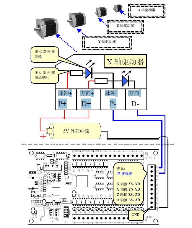
18 Five. USB motion control card wiring diagram 1. X, Y, Z, A axis output. You can use the following two kinds of power supply: Internal power supply / external power supply. I. Use the power motion control card, driver, according to the need to install the appropriate current limiting resistor. 18 II. External power supply, drive, according to the need to install the appropriate current limiting resistor.
19 19

20 2) Input: Voltage 5V. You can use the following two kinds of power supply: Internal power supply / external power supply. I. Use of an internal power motion control card, driver input 20

21 II. A 5V external power supply to drive input. Note: external power supply voltage exceeds 5V or more, need an external current limiting resistor in series (on the board for the 330 ohm current limiting resistor). Resistance value: 24V at 3K, 12V at 1.5K. 21


22 3 sensor wiring and configuration I. PNP sensor, driver input. Mach3 input configuration 22


23 II. NPN sensors, driver input. Mach3 input configuration 23

24 4 outputs: 8 outputs for maximum control voltage 24V, maximum output low drive current 500mA, or output Impedance. I. Use of the internal motion control card power supply, LED driver Drive a small current load, such as LED, driver-enable control, you can directly use the internal power supply. 24

25 II. Using 5-24V external power supply, drive 500mA relay. Driving high current loads such as relays, etc., need to use an external power supply. 25


26 6. External magnification knob Complete the first step in the manual "Installation Preparation." The rate knob and USB card rate knob seat EXT0 (J16) connection. Mach3 菜单中 Config=>Config Plugins, 进入 PlugIn Control and Activation 26


27 After configuration, click "OK". Rotation rate knob, Mach3 interface corresponding to the FRO%, SRO% value immediately changes. Rotation rate knob, Mach3 interface corresponding to the Slow Jog Rate% value immediately changes. 27

28 7. spindle speed analog output Software Configuration Into the spindle set "Spindle Setup", check "Use Spindle Motor Output", "PWM Control". In PWMBase Freq. Enter the desired frequency, number 1-60, in units of KHz. 28
.")
29 Spindle speed signal PWM phase configuration Other spindle configuration instructions, refer to "Mach3Chinese-Documents.pdf" in "5.5.6 Setting the spindle motor." Spindle Test In the manual input interface on the input data box: Enter the "M3", you can hear the spindle relay (if configured and installed the spindle forward relay). Enter "S10000", spindle rotation. Enter the "M5", spindle stop switch. 29

30 Speed analog output interface schematic 30
")
31 External power supply wiring (output 0-10V) 31


32 8.spindle speed USB card configuration dialog Click "Config" dialog box after the USB card configuration 32


33 Spindle speed display Measured speed will be displayed in Mach3 It may also open the spindle speed real-time waveform display Below: a measure of the speed curve when starting the spindle 33
 output, the OC output.")
34 Velocity diagram of the Hall element working Hall element "44E" is an open collector (open drain) output, the OC output. 34


35 USB card speed input interface schematic Speed USB card terminal Hall element 35

36 IX. Automatic tool Wiring of the knife 36

37 Automatic software configuration tool 37

38 3. VB code for the tool, enter in the VB editor. USB card provided with the usbmove.zip knife demo VB code for "M7101.m1s", use Notepad to open. 4. Test: Click on "Auto Tool Zero" button to test the action of the knife. VB code for the knife shows, according to the actual need to change. 38

39 X. electronic hand wheel Internal power supply Note: 1. "DC5V" on-board isolated power module output (internal power). Voltage of 5V, the maximum output current of 120mA. (2) such as electronic hand wheel with 12V/24V, or total current load capacity of the USB card, please use the external power supply. 39

40 External power supply 40

41 Software Configuration Mach3 in electronic hand wheel configuration, as shown below: (Config => Ports and Pins) 41


42 11. USB motion control card read-ahead buffer setting Performance based on the PC used to set read-ahead cache. Adjust the buffer time to make run smooth. 42
Ver1.09. Support: Automatic tool-setting, electronic hand wheel, software limit, software backlash.
 USB Motion Control Card Manual Ver1.09 Features: Support all the Mach3 version,including the latest edition :Mach3 R3.042.040. Support all the Windows version,including the latest edition :Windows7. No
Motion Control Card Manual
 Motion Control Card Manual motion control card features: 1. Supports all Mach3 versions, including the Mach3 R3.042.040 version. 2. Supporting Windows series, no need to install any USB drivers and plug.
Mach3 USB Motion Card Installation Manual
 Mach3 USB Motion Card Installation Manual Features: Fully supporting all Mach3 versions, including the Mach3 R3.043.066 version. Supporting Windows series, including Windows2000/XP/Vista/Win7/Win8/Win10.
MAC3-USBCARD-MK-Instructions 济南优本机械设备有限公司 Jinan Acctek Machinery Co.,Ltd MACH3 Suitable systems:mach3
 Suitable systems:mach3-1 - MAC3-USBCARD-MK-Instructions Model: XHC-MK4:With USB interface, 4-axis motion control card XHC-MK6:With USB interface, 6-axis motion control card MACH3 - 2 - Features: Fully
USER S MANUAL. C32- DUAL PORT MULTIFUNCTION CNC BOARD Rev. 4
 USER S MANUAL C32- DUAL PORT MULTIFUNCTION CNC BOARD Rev. 4 August, 2012 USER'S MANUAL TABLE OF CONTENTS Page # 1.0 FEATURES... 1-1 2.0 SPECIFICATIONS... 2-3 3.0 BOARD DESCRIPTION... 3-4 4.0 FUNCTIONAL
HDBB Breakout board user s manual
 HDBB Breakout board user s manual The HDBB breakout board was designed to use with our Whale2(-T)*, Whale3, Mammut* and Dugong servo drives or with any other third party stepper or servo drives which using
IO3-R2 BREAKOUT BOARD
 IO3-R2 BREAKOUT BOARD DESCRIPTION Breakout board IO3-R2 (Revision R2) has digital buffer for STEP/DIR/ENA command signals and as such it is particularly suitable for the connection up to 4 microstep drives
USER S MANUAL. C11S- MULTIFUNTCION CNC BOARD Rev. 1.2
 USER S MANUAL C11S- MULTIFUNTCION CNC BOARD Rev. 1.2 SEPTEMBER 2014 User s Manual Page i TABLE OF CONTENTS Page # 1. Overview... 1 2. Features... 1 3. Specifications... 3 4. BOARD DESCRIPTION... 4 5. Special
Apollo I Breakout Board User s Manual
 MACHMOTION Apollo I Breakout Board User s Manual 1/14/2012 Everything you need to know to set up and use your Apollo I Breakout Board. MachMotion Version 1.0.1 2 P a g e M a c h M o t i o n Copyright 2012,
PP-BOB2-V1.0 PARALLEL PORT BREAKOUT BOARD
 PP-BOB2-v1 PARALLEL PORT BREAKOUT BOARD Document: Operation Manual Document #: T17 Document Rev: 2.0 Product: PP-BOB2-v1.0 Product Rev: 1.0 Created: March, 2013 Updated: Dec, 2014 THIS MANUAL CONTAINS
USER S MANUAL VER.1. C11G- MULTIFUNTCION CNC BOARD Rev. 9
 USER S MANUAL VER.1 C11G- MULTIFUNTCION CNC BOARD Rev. 9 MARCH, 2017 User s Manual Page i USER'S MANUAL TABLE OF CONTENTS Contents Page # 1.0 OVERVIEW... 1 2.0 FEATURES... 1 3.0 SPECIFICATIONS... 2 4.0
USER S MANUAL. C33 - MULTIFUNCTION ROUTER BOARD BOARD Rev. 4
 USER S MANUAL C33 - MULTIFUNCTION ROUTER BOARD BOARD Rev. 4 June 2013 USER'S MANUAL TABLE OF CONTENTS Page # Contents 1.0 OVERVIEW... 3 2.0 FEATURES... 3 3.0 SPECIFICATIONS... 4 4.0 FUNCTIONAL BLOCK DIAGRAMS...
UCBB dual port breakout board user's manual
 UCBB dual port breakout board user's manual 1/14 Contents 1 Features 2 Dimensions 3 Connectors 3.1 Screw terminals 3.2 IDC ports 3.3 Powering 3.4 Outputs 3.5 Inputs 4 LED indicators 5 Example connections
USER S MANUAL. C11- MULTIFUNTCION CNC BOARD Rev. 9.9
 USER S MANUAL C11- MULTIFUNTCION CNC BOARD Rev. 9.9 FEBRUARY, 2015 User s Manual Page i TABLE OF CONTENTS Page # 1. Overview... 1 2. Features... 1 3. Specifications... 3 4. BOARD DESCRIPTION... 4 5. Special
C33- MULTIFUNCTION ROUTER BOARD Rev. 2
 C33- MULTIFUNCTION ROUTER BOARD Rev. 2 User manual Rev. 1 1. Overview This card provides an easy way of interfacing your router based spindle with your steeper motor driver board. This board includes a
USER S MANUAL. C35S- QUICK SETUP BREAKOUT BOARD Rev. 1.3
 USER S MANUAL C35S- QUICK SETUP BREAKOUT BOARD Rev. 1.3 FEBRUARY, 2015 USER'S MANUAL TABLE OF CONTENTS Page # Contents 1.0 OVERVIEW... 1 2.0 FEATURES... 1 3.0 SPECIFICATIONS.... 2 4.0 BOARD DESCRIPTION...
Hardware Manual CNC760
 Hardware Manual CNC760 Revision 3 6 December, 2017 Released Copyright 2017 by Eding CNC History: Revision Date Author 1 22-5-2017 AB 2 23-6-2017 AB 3 6-12-2017 AB Revision overview: Revision Remarks 1
C11G- MULTIFUNTCION CNC BOARD Rev. 8.2
 C11G- MULTIFUNTCION CNC BOARD Rev. 8.2 User manual Rev. 2 1. Overview This card has been designed to provide a flexible interface and functions to your computer projects, by using the parallel port control
DDUM CARD V1.0 Simple Description (English)
") DDUM CARD V1.0 Simple Description (English) Chapter 1 Overview 1.1 Simply Introduction 1.2 Requirements of Computer 1.3 Appearance and size of poduct 1.4 Notes and Cautions Chapter 2 Detailed Features
DDUM CARD V1.0 Simple Description (English) Chapter 1 Overview 1.1 Simply Introduction 1.2 Requirements of Computer 1.3 Appearance and size of poduct 1.4 Notes and Cautions Chapter 2 Detailed Features
Profi4 Main Board Manual
 Profi4 Main Board Manual A. Scope of application It is used to run the signal processing of the host computer ( LPT port ), with MACH 3 CNC system software, and the peripheral machine dynamic electrical.
C35- QUICK SETUP BREAKOUT BOARD Rev. 1.1
 C35- QUICK SETUP BREAKOUT BOARD Rev. 1.1 User manual Rev. 1 1. Overview This card provides an easy way of interfacing your inputs and outputs from the parallel port. It provides terminals and RJ45 for
C23- DUAL PORT MULTIFUNCTION CNC BOARD Rev. 3.1
 C23- DUAL PORT MULTIFUNCTION CNC BOARD Rev. 3.1 User manual Rev. 2 1. Overview This card has been designed to provide a flexible interface and functions to computer CNC projects, by using the parallel
changzhou RATTM Motor Co.,Ltd
 请在这里输入您的公司名称 Changzhou RATTM Motor Co.,Ltd changzhou RATTM Motor Co.,Ltd tonyswj@hotmail.com http://www.aliexpress.com/store/704350 http://www.aliexpress.com/store/907217 USB MACH3 CARD V1.0 Simple Description
ACORN User Guide For Revision (Aka Acorn_rev3) Updated 1/23/17
 Updated 1/23/17") ACORN User Guide For Revision 171025 (Aka Acorn_rev3) Updated 1/23/17 Overview ACORN is technically a breakout board for the BeagleBone Green or BeagleBone Black embedded computer. The remainder of this
ACORN User Guide For Revision 171025 (Aka Acorn_rev3) Updated 1/23/17 Overview ACORN is technically a breakout board for the BeagleBone Green or BeagleBone Black embedded computer. The remainder of this
PMDX-424 SmartBOB-IsoUSB For use with Mach4
 PMDX-424 SmartBOB-IsoUSB For use with Mach4 Quick Start Guide Document Revision: 0.6 Date: 8 April 2016 Circuit Board Revisions: PCB-525A and PCB-525B PMDX Web: http://www.pmdx.com 9704-D Gunston Cove
User's Manual. For ST-6560V3. Version All Rights Reserved
 User's Manual For ST-6560V3 Version 2.0 2016.08.25 All Rights Reserved 1. Key Features Toshiba TB6560AHQ chip - High power, maximum current 3.5A Resolution 1, 1/2, 1/8, 1/16 micro stepping output Working
PP-BOB2-V2.0 PARALLEL PORT BREAKOUT BOARD
 PP-BOB2-V2 PARALLEL PORT BREAKOUT BOARD Document: Operation Manual Document #: T18 Document Rev: 1.0 Product: PP-BOB2-V2.0 Product Rev: 1.0 Created: October, 2015 THIS MANUAL CONTAINS INFORMATION FOR INSTALLING
BMS: Installation Manual v2.x - Documentation
 Page 1 of 7 BMS: Installation Manual v2.x From Documentation This section describes how external peripheral devices are connected and additional functions of the BMS are used. I you have not done so already,
USB I/O-CARD WITH 32 INPUTS
 ORDERING NO. 4 016138 489224 Best. Nr. 502176 Control systems, switchgear cabinets Building automation, Home Automation Model construction, model railroads Step motor control and actuators I/O-card for
Centroid ACORN CNC controller Specification and Use Guide Updated 8/3/17. Overview
 Centroid ACORN CNC controller Specification and Use Guide Updated 8//7 Overview ACORN is technically a CNC control breakout board for the BeagleBone Green or BeagleBone Black embedded computer the Beagle
PMDX-411 SmartBOB-USB with DB-25 Connector For use with Mach4
 PMDX-411 SmartBOB-USB with DB-25 Connector For use with Mach4 Quick Start Guide Document Revision: 0.4 Date: 6 May 2015 This document applies to units built on artwork revision PCB-522B. This is a rough
UB1. Owner s manual. Doc E1.5Rev0 (8/23/2017) for PCB ver Page 1
 for PCB ver Page 1") UB1 Owner s manual Doc E1.5Rev0 (8/23/2017) for PCB ver 1.5 www.cncroom.com Page 1 Introduction It is perhaps well understood that in an industrial environment, personal computers, motion control boards
UB1 Owner s manual Doc E1.5Rev0 (8/23/2017) for PCB ver 1.5 www.cncroom.com Page 1 Introduction It is perhaps well understood that in an industrial environment, personal computers, motion control boards
Apollo III INSTALLATION MANUAL
 Apollo III INSTALLATION MANUAL 2 P a g e 5/1/14 N0112 This manual covers the setup and configuration of the Apollo III motion controller connected to the control using Mach3. Formatting Overview: Menus,
C10- PARALLEL PORT INTERFACE CARD Rev. 8
 C10- PARALLEL PORT INTERFACE CARD Rev. 8 User manual Rev. 1 1. Overview This card provides an easy way of interfacing your inputs and outputs from you parallel port. It provides terminals for the connections
HARDWARE MANUAL TMCM-1613 TMCM-1613-REC. Hardware Version V TRINAMIC Motion Control GmbH & Co. KG Hamburg, Germany.
 MODULES FOR BLDC MOTORS MODULES Hardware Version V 1.10 HARDWARE MANUAL + + TMCM-1613 + + Single Axis BLDC Controller / Driver Block-commutation Hall-sensor based Analog+digital inputs / outputs Up-to
4Trio Motion Technology3
 4Trio Motion Technology3 MC 202 Motion Controller Product Overview 3-1 3.0 Motion Coordinator 202 Description 3.1 Motion Coordinator 202 The Motion Coordinator 202 is a miniature stepper/servo positioner
CPU5A Economy Series USBCNC software included. Features
 CPU5A Economy Series 125 KHz step frequency, 4 axes. Card size 100x100mm. USB 2.0 connection. 100 Mbit Ethernet connection (*). 5 Status LED's. Full 4 axes interpolation (*). 7 Standard CNC outputs. 0-10V
Novusun Controller Wiring and MACH3 Software Setup
 Novusun Controller Wiring and MACH3 Software Setup V1.0 01 2019 Open Source Mechatronics LTD 2019 Safety Statement The author of this document is not liable or responsible for any accidents, injuries,
HiCON Integra pn7766
 HiCON Integra pn7766 Ethernet Motion Controller Data Acquisition System Logic Controller User Guide Document Revision 1.0 (Updated March 12, 2013) 2013 Vital Systems Inc Phoenix, AZ USA For more information
Digital Servo Drive. For Brushless Motor or Brushed Motor MDSC4805 / MDSC4810 / MDSC4830 / MDSC4850. Datasheet V1.1. Jun 2, 2017
 Digital Servo Drive For Brushless Motor or Brushed Motor MDSC4805 / MDSC4810 / MDSC4830 / MDSC4850 Datasheet V1.1 Jun 2, 2017 Copyright @ Mach Motion Products, INC. 2017 All rights reserved. No part of
PMDX-416 SmartBOB-OptoUSB For use with Mach4
 PMDX-416 SmartBOB-OptoUSB For use with Mach4 User s Manual Document Revision: 1.0 Date: 1 July 2016 Circuit Board Revisions: PCB-534A PMDX Web: http://www.pmdx.com 9704-D Gunston Cove Rd Phone: +1 (703)
PLCM-B1 Breakout board for PLCM-E3/E3p controller
 www.purelogic.ru User manual CONTENTS: 1. General information... 2 2. Delivery set... 2 3. Technical specifications... 3 4. Key features... 4 5. Sockets purpose and indication... 6 6. Connection... 11
Manual 5 Axis CNC Interface Breakout Board Model#-DB25-1R5AM
 Manual 5 Axis CNC Interface Breakout Board Read this manual carefully before making connections to the board. Store this manual away for further reference. Safety Notes: The electronics of the control
Breakoutboard Rev.2 for Estlcam
 Breakoutboard Rev.2 for Estlcam 1 Stefan Gemeinert,Frühlingstrasse 8 85253 Erdweg Operation Manual All rights to these operating instructions remain with cnc-technics. Texts, information and illustrations
D115 The Fast Optimal Servo Amplifier For Brush, Brushless, Voice Coil Servo Motors
 D115 The Fast Optimal Servo Amplifier For Brush, Brushless, Voice Coil Servo Motors Ron Boe 5/15/2014 This user guide details the servo drives capabilities and physical interfaces. Users will be able to
HY-TB5 CNC Series Manual five axis
 HY-TB5 CNC Series Manual ------ five axis Thank you for choosing our products better and faster for you to use NC products, please read this manual, make sure the pump is started before the water-cooled
HARDWARE MANUAL TMCM-1613 TMCM-1613-REC. Hardware Version V TRINAMIC Motion Control GmbH & Co. KG Hamburg, Germany.
 MODULES FOR STEPPER MOTORS MODULES Hardware Version V 1.10 HARDWARE MANUAL + + TMCM-1613 + + Single Axis BLDC Controller / Driver Block-commutation Hall-sensor based Analog+digital inputs / outputs Up-to
Breakoutboard for ESS Smoothstepper
 Breakoutboard for ESS Smoothstepper Operation Manual All rights to these operating instructions remain with cnc-technics. Texts, information and illustrations of these operating instructions may not be
C10S- PARALLEL PORT INTERFACE CARD Rev. 1.4
 USER S MANUAL VER.1 C10S- PARALLEL PORT INTERFACE CARD Rev. 1.4 SEPTEMBER, 2016 User s Manual Ver.1 Page i USER'S MANUAL TABLE OF CONTENTS Page # 1. OVERVIEW... 1 2. FEATURES... 1 3. SPECIFICATIONS...
MachBob2 (MB2) Owner Instruction manual. Doc E1.2 (22/03/59) Page 1
 Owner Instruction manual. Doc E1.2 (22/03/59) Page 1") MachBob2 (MB2) Owner Instruction manual Doc E1.2 (22/03/59) www.cncroom.com Page 1 Introduction It is known that the environment in the industry often have interference from electrical power such as motors,
MachBob2 (MB2) Owner Instruction manual Doc E1.2 (22/03/59) www.cncroom.com Page 1 Introduction It is known that the environment in the industry often have interference from electrical power such as motors,
MK5 5-Axis Controller
 MK5 5-Axis Controller Technical Reference Manual PCB Rev 1.0 2010 SOC Robotics, Inc. 1 Manual Rev 0.91 Introduction The MK5 is a 5-Axis breakout board that accepts the MM120, MM130, MM133 or MM220 stepper
AXBB-E ethernet motion controller and breakout board user's guide
 AXBB-E ethernet motion controller and breakout board user's guide Version of this document: 1.0002 1/29 Contents 1.Description of the AXBB-E device. 2.Safety notes. 3.Physical installation of the device.
USER S MANUAL VER.1. C10D- PARALLEL PORT INTERFACE CARD BOARD Rev. 1
 USER S MANUAL VER.1 C10D- PARALLEL PORT INTERFACE CARD BOARD Rev. 1 MARCH 2018 User s Manual Page i USER'S MANUAL TABLE OF CONTENTS Contents Page # 1.0 OVERVIEW... iii 2.0 FEATURES... iii 3.0 SPECIFICATIONS...
USER S MANUAL VER.2. C76- MULTIFUNCTION CNC BOARD Rev. 1.4
 USER S MANUAL VER.2 C76- MULTIFUNCTION CNC BOARD Rev. 1.4 MARCH 2018 User s Manual Page i USER'S MANUAL TABLE OF CONTENTS Contents Page # 1.0 FEATURES... 1 2.0 I/O SPECIFICATIONS... 2 3.0 BOARD DESCRIPTION...
Stepper Drive Setup Guide
 MACHMOTION Stepper Drive Setup Guide 1/21/2011 Everything you need to know to connect your stepper motors to the MachMotion stepper drives. MachMotion Version 1.0.1 2 P a g e Copyright 2011, MachMotion.com
MAXREFDES108#: NON-ISOLATED 12V/1A POE POWERED DEVICE POWER SUPPLY
 System Board 6289 MAXREFDES108#: NON-ISOLATED 12V/1A POE POWERED DEVICE POWER SUPPLY To meet the increasing demands for non-isolated Power over Ethernet (PoE) power solutions, Maxim has developed innovative,
DMX-K-DRV. Integrated Step Motor Driver + (Basic Controller) Manual
 Manual") DMX-K-DRV Integrated Step Motor Driver + (Basic Controller) Manual Table of Contents 1. Introduction... 4 Features... 4 2. Part Numbering Scheme... 5 3. Electrical and Thermal Specifications... 6 Power
DMX-K-DRV Integrated Step Motor Driver + (Basic Controller) Manual Table of Contents 1. Introduction... 4 Features... 4 2. Part Numbering Scheme... 5 3. Electrical and Thermal Specifications... 6 Power
Hardware Manual 1240i-485
 Hardware Manual -485 Intelligent Step Motor Driver with Multi-drop RS-485 Interface 920-0033 A 7/6/2010 motors drives controls -2- Table of Contents Introduction...4 Features...4 Block Diagram...4 Getting
DMX-K-DRV Integrated Step Motor Driver Manual
 Tu Sitio de Automatización! DMX-K-DRV Integrated Step Motor Driver Manual Table of Contents 1. Introduction... 4 2. Part Numbering Scheme... 4 3. Dimensions... 5 NEMA 11 DMX-K-DRV... 5 NEMA 17 DMX-K-DRV...
(MKX version ) Manual
 Manual") MACH3 Motion Card (MKX version ) Manual 1. Mach3 Software installation 2. Drive and configuration file installation 2.1 Drive installation 2.2 Configuration file installation 2.3 Macro code file installation
MACH3 Motion Card (MKX version ) Manual 1. Mach3 Software installation 2. Drive and configuration file installation 2.1 Drive installation 2.2 Configuration file installation 2.3 Macro code file installation
EM705 2-phase Digital Stepper Drive
 EM705 2-phase Digital Stepper Drive 20-70V, 0.35-5A, Sensorless Stall Detection, Pre-Matching Motor Sensorless stall detection eliminates cost of feedback devices and time of cable connection Super-low
AG300 Family CTL01-3A-03, AMP01-2A-02
 AG300 Family CTL01-3A-03, AMP01-2A-02 Hardware User's Manual Page 1 Revision control table Version Description Date 1.0 Initial (based on Hardware Manual of previous hardware versions) April 27, 2016 1.1
MaxStepper Serial Step and Direction Pulse Generator. User Manual
 MaxStepper Serial Step and Direction Pulse Generator User Manual 2007 Kellyware 9/20/2007 WWW.KELLYWARE.COM Table of Contents Table of Contents... 2 Parts List... 3 Key Features... 3 Introduction... 4
EM806 2-phase Digital Stepper Drive
 EM806 2-phase Digital Stepper Drive 24-80V, 0.35-6A, Sensorless Stall Detection, Pre-Matching Motor Sensorless stall detection eliminates cost of feedback devices and time of cable connection Super-low
imach III P3A and P3A-E CNC Control Pendant
 www.vistacnc.com - 1 - imach III P3A and P3A-E CNC Control Pendant www.vistacnc.com - 1 - imach III P3A Pendant Manual v. 3.4 www.vistacnc.com - 2 - PREFACE Any machine tool, including computer controlled
imach III P5A and P5A-E CNC Control Pendant
 www.vistacnc.com - 1 - imach III P5A and P5A-E CNC Control Pendant www.vistacnc.com - 1 - imach III P5A Pendant Manual v. 3.4.0 www.vistacnc.com - 2 - PREFACE Any machine tool, including computer controlled
Galil Motion Control. DMC - 18x6. Datasheet (US ONLY)
") Galil Motion Control DMC - 18x6 Datasheet Galil Motion Control 270 Technology Way, Rocklin, CA 1-916-626-0101 (US ONLY) 1-800-377-6329 Product Description The DMC-18x6 PCI bus motor controllers belong
Galil Motion Control DMC - 18x6 Datasheet Galil Motion Control 270 Technology Way, Rocklin, CA 1-916-626-0101 (US ONLY) 1-800-377-6329 Product Description The DMC-18x6 PCI bus motor controllers belong
DigiSpeed-SD DC-06. Isolated Control Voltage Generator User s Guide. DigiSpeed-SD PCB Ver:3.0 Mach3 Ver: 2.+ DigiSpeed-SD - Users Guide Page 1
 DigiSpeed-SD - Users Guide Page 1 Updated: 4 th May 2011 DigiSpeed-SD DC-06 Isolated Control Voltage Generator User s Guide DigiSpeed-SD PCB Ver:3.0 Mach3 Ver: 2.+ DigiSpeed-SD - Users Guide Page 2 Homann
Release Note. How to Use the OptoCon Connection Module. 1 Introduction. Option C Revision 4 Revised 8/13/98
 33 South La Patera Lane Santa Barbara, CA 93117-3214 ph (805) 681-3300 fax (805) 681-3311 tech@motioneng.com www.motioneng.com Release Note How to Use the OptoCon Connection Module Option C002-0007 Revision
Central-I Family. CiG1-AMP01-1A-01-00
 Central-I Family CiG1-AMP01-1A-01-00 Hardware User's Manual Central-ICentral-I - Hardware Manual -Amplifier CiG1-AMP01- Page 1 Revision control table Version Description Date 1.0 Initial (based on Hardware
Breakoutboard für UC400ETH
 Breakoutboard für UC400ETH Operation Manual All rights to these operating instructions remain with cnc-technics. Texts, information and illustrations of these operating instructions may not be reproduced,
Preliminary Datasheet MX Axis Stepper Drive with Breakout Board & I/O s. Preliminary V1.0
 Preliminary Datasheet MX4660 4-Axis Stepper Drive with Breakout Board & I/O s Preliminary V1.0 Features Power up to 4 stepper motors of NEMA 17, 23, 24, or 34 Sophisticated stepper motor control based
Central-I Family. CiG1-AMP01-1A-01-00
 Date: Sunday, Aug14, 2016 Version: 1.16 Central-I Family CiG1-AMP01-1A-01-00 Hardware User's Manual Page 1 Date: Sunday, Aug14, 2016 Version: 1.16 Revision control table Version Description Date 1.0 Initial
User Manual For DM332T. 2-Phase Digital Stepper Drive. Designed by StepperOnline. Manufactured by Leadshine
 User Manual For DM332T 2-Phase Digital Stepper Drive Designed by StepperOnline Manufactured by Leadshine #7 Zhongke Road, Jiangning, Nanjing, China T: 0086-2587156578 Web site: www.omc-stepperonline.com
I/O Expansion Module Installation & Reference
 Overview The In-Sight vision sensor supports up to ten discrete inputs and ten discrete outputs. Two inputs and two outputs are built-in to the In-Sight processor. The remaining eight inputs and outputs
FEATURES: DESCRIPTION: APPLICATIONS: SPECIFICATIONS: Electrical Specifications of Drive: Operating Environment: [Geben Sie Text ein]
![FEATURES: DESCRIPTION: APPLICATIONS: SPECIFICATIONS: Electrical Specifications of Drive: Operating Environment: [Geben Sie Text ein]](/thumbs/93/111844613.jpg "FEATURES: DESCRIPTION: APPLICATIONS: SPECIFICATIONS: Electrical Specifications of Drive: Operating Environment: [Geben Sie Text ein]") ist-09 ist-0 FEATURES: Integrated compact size for saving mounting space & setup time, and reducing electrical interference Anti-Resonance provides optimal torque and nulls mid-range instability Motor
ist-09 ist-0 FEATURES: Integrated compact size for saving mounting space & setup time, and reducing electrical interference Anti-Resonance provides optimal torque and nulls mid-range instability Motor
F7000N Tip Alignment Device Guide
 F7000N Tip Alignment Device Guide - Page 1 - Contents i. Tip Alignment Device Overview... 3 ii. Hardware... 4 iii. Hardware Installation... 5 iv. Setting the Device... 5 v. Device Movement... 8 vi. Tip
CNC4X35A 4 axis Stepper Motor Control Board
 CNC4X35A 4 axis Stepper Motor Control Board Just connect bipolar stepper motors, power and a parallel port signal source CNC4X35A 4 axis Stepper Motor Control Board Specs: Designed for easy construction/retrofit
In-Sight 7010C/7200C/7400C
 The following sections list general specifications for the In-Sight vision system. Vision System Specifications Table 3-1: Vision System Specifications Specifications Minimum Firmware Requirement Job/Program
UNIVERSAL MOTION INTERFACE (UMI) ACCESSORY
 ACCESSORY") USER GUIDE UNIVERSAL MOTION INTERFACE (UMI) ACCESSORY Contents This user guide describes how to use the UMI-77, UMI-A, UMI-Flex, and UMI-Flex accessories. Introduction... What You Need to Get Started...
USER GUIDE UNIVERSAL MOTION INTERFACE (UMI) ACCESSORY Contents This user guide describes how to use the UMI-77, UMI-A, UMI-Flex, and UMI-Flex accessories. Introduction... What You Need to Get Started...
NX-EC0/ECS/PG0 CSM_NX-EC0_ECS_PG0_DS_E_2_2
 NX-series Position Interface Unit NX-EC0/ECS/PG0 CSM_NX-EC0_ECS_PG0_DS_E_2_2 NX Units for fast and precise positioning control Incremental Encoder Input Unit (NX-EC0) More precise timing control by synchronizing
MicrostepPLD Driver Manual Version 6/13/2006
 MicrostepPLD Driver Manual Version 6/13/2006 Embedded Acquisition Systems 2517 Cobden Street Sterling Heights, MI 48310 http://www.embeddedtronics.com email sales@embeddedtronics.com copyright 2003-2004
Issue : 1.1 Date : 19/1/2004. Trigger IO. C-Cam Technologies. a division of. Vector International 1 / 6
 Trigger IO C-Cam Technologies a division of Vector International 1 / 6 1 Trigger IO connector Trigger IO connector Camera with LS interface Trigger IO connector Camera with USB interface 2 / 6 1.1 Pin
MD3. Microstepping Motor Driver Page 1 of 7. Description. Software. Mechanical Drawing. Features
 Page 1 of 7 The MD3 is a stepper motor driver with an integrated motion controller that is capable of driving size 14 to 42 stepper motors from 2 to 256 microsteps per step. Peak motor currents are selectable
HY-TB3DV-S intelligent 3-axis drive board manual
 HY-TB3DV-S intelligent 3-axis drive board manual Thank you for choosing our company's products, the use of CNC products better and faster for you, please read this manuai Features: Features 1: integrated
CNC4PC. MULTIFUNCTION CNC BOARD Rev2
 CNC4PC Manual MULTIFUNCTION CNC BOARD Rev2 Overview This card has been designed to provide a flexible interface and functions to your computer projects, by using the parallel port control software. This
MACH3 Breakout Board
 SUPPORT CNC SYSTEM: MACH3 Only MACH3 Breakout Board MKX-V Specification USB 4-axis Card System :MACH3 mode l:mk4- V QC:01 2016-9-13 USB MOTION CARD 电源 0V 电源 24V Size:184x127x30mm Model No.: MK3-V:USB Cable,3
eace PLC Velocio s Embedded Ace (eace) PLC
 PLC") Velocio s Embedded Ace (eace) PLC eace PLC The eace PLC is a member of the Velocio s groundbreaking series of programmable logic controllers. These PLCs introduce revolutionary new concepts, capabilities,
Velocio s Embedded Ace (eace) PLC eace PLC The eace PLC is a member of the Velocio s groundbreaking series of programmable logic controllers. These PLCs introduce revolutionary new concepts, capabilities,
Digital DRIVE for Brushless motor MD Serial
 Digital DRIVE for Brushless motor MD Serial Installation guide Read manual before installing and respect all indications with this icon: MD-GI/EN Table of Contents 1- Introduction... 3 1-1- Warning...
USER S MANUAL VER.1. C10- PARALLEL PORT INTERFACE CARD BOARD Rev. 11
 USER S MANUAL VER.1 C10- PARALLEL PORT INTERFACE CARD BOARD Rev. 11 FEBRUARY, 2017 User s Manual Page i USER'S MANUAL TABLE OF CONTENTS Contents Page # 1.0 OVERVIEW... iii 2.0 FEATURES... iii 3.0 SPECIFICATIONS...
Manual. Model#-DB25M-3R6A. 6 Axis CNC Interface Breakout Board. Lastest update : Feb Store this manual away for further reference.
 Manual 6 Axis CNC Interface Breakout Board Model#-DB25M-3R6A Lastest update : Feb 2016 Read this manual carefully before making connections to the board. Store this manual away for further reference. Safety
UNIPORT V2. Uniport V2
 UNIPORT V2 Uniport V2 USB powered Parallel port interconnection board with optical isolated inputs, buffered outputs, charge pump interlock and power relays Specification Full optical isolation of all
RASPBERRY PI MEGA-IO EXPANSION CARD USER'S GUIDE VERSION 2.3
 RASPBERRY PI MEGA-IO EXPANSION CARD www.sequentmicrosystems.com USER'S GUIDE VERSION 2.3 GENERAL DESCRIPTION... 2 BOARD LAYOUT... 3 BLOCK DIAGRAM... 4 COMPONENT DESCRIPTION... 5 CONFIGURATION JUMPERS...
USER S MANUAL VER.3. C25- SMOOTH STEPPER LPT BOARD Rev. 5
 USER S MANUAL VER.3 C25- SMOOTH STEPPER LPT BOARD Rev. 5 MAY, 2017 User s Manual Page i USER'S MANUAL TABLE OF CONTENTS Contents Page # 1.0 FEATURES... 1 2.0 SPECIFICATIONS... 1 3.0 FUNCTIONAL BLOCK DIAGRAMS...
MP6500 Stepper Motor Driver, Digital Current Control
 This breakout board for the MPS MP6500 micro stepping bipolar stepper motor driver is Pololu s latest stepper motor driver. The module has a pinout and interface that are very similar to that of our popular
SYNTEC. 6A Controller Hardware Specifications. Description: General Specifications: System Roadmap:
 Description: The Syntec 6A Series Controllers are based on embedded systems architectures and are equipped with 8-inch LCD displays and universal text key panels. The systems come with integrated servo
Thank you for choosing our company's products, the use of CNC products better and faster for you, please read this manual
 HY-TB3DV-HH(HL) 3-axis drive board manual Product Link: http://www.thanksbuyer.com/cnc-very-professiona l-3-axis-3-5a-tb6560-stepping-motor-driver-cont roller-lcd-display-cnc-router-24898 Thank you for
UIM2901-5A. Page 2. UI Robot Technology Co. LTD M EN. Please pay attention to the following before using the UIROBOT products:
 User Manual MACH3 Breakout Board Please pay attention to the following before using the UIROBOT products: UIROBOT products meet the specification contained in their particular Data Sheet. UIROBOT will
Branch PLC. Velocio s Branch PLC
 Velocio s Branch PLC Branch PLC The Branch PLC is a member of the Velocio s groundbreaking series of programmable logic controllers. These PLCs introduce revolutionary new concepts, capabilities, performance
Ether-Mach Mach3 Plugin Guide
 Ether-Mach Mach3 Plugin Guide Ethernet Motion Controller for Artsoft's Mach3 CNC. Features Connects over a dedicated 100 Mbps Ethernet connection. Smooth motion on 6 coordinated axes plus a spindle motor.