CNC4X35A 4 axis Stepper Motor Control Board
|
|
|
- Jemima Hensley
- 6 years ago
- Views:
Transcription

 On board switch allowing 4 th axis to shadow Y axis or independent Support for up to 5 external input signals (usually used for Limit X, Y, Z, Probe and E-Stop) On board relay for easy Spindle")
1 CNC4X35A 4 axis Stepper Motor Control Board Just connect bipolar stepper motors, power and a parallel port signal source CNC4X35A 4 axis Stepper Motor Control Board Specs: Designed for easy construction/retrofit of desktop/small benchtop milling/engraving machine Direct connection to parallel port computer Drives 4 stepper motors in bipolar microstepping mode Wide range of motors (5-30V and 0.7-3A) On board switch allowing 4 th axis to shadow Y axis or independent Support for up to 5 external input signals (usually used for Limit X, Y, Z, Probe and E-Stop) On board relay for easy Spindle ON/OFF setup LED indicator for Power, input signals and driver status All input ports from computer are buffered and Schmidt triggered Compatible with a large number of programs (Mach2/3, Master5, EMC,KCAM, USBCNC etc.) Each of 4 axis features : PWM current control dual D-Mos H-Bridge.6 or 1.5 or 2.25 or 3 Amp (0.56 or 1.4 or 2.1 or 2.8 Vers.) Current Limit adjustable by dip switch Full, Half, Quarter, & 1/16 Microstepping Resolution Current Decay Mode Selection From Fast Decay to Slow-Decay Modes by dip switch Thermal Shutdown and Crossover Current Protection Overview This document describes configuration and operation of CNC4X35A stepper motor driver boards. The CNC4X35A provides an interface between a step pulse generator (PC, embedded controller etc) and up to 4 stepper motors. Power supply : min 15 V - max.32v Important precautions on using CNC4X25A driver Do NOT reverse polarity on board power supply (board will be damaged imediately). At power supply connector it is figured a + sign. There should be conected positive polarity Do NOT connect or disconnect motors when the drive is powered.

2 Do NOT allow Vsuply to exceed +32VDC, STEP & DIR lines to exceed +5.0 VDC Do NOT connect scopes or any other test devices to the motor leads Use of a cooling fan is recommended for systems operating at or near the maximum current rating Power Each axis can be separately setup to deliver different maximum current levels by adjusting on-board configuration switches. Configuration switches are at the right of coil connectors. (In this picture all switches are off.) Switches number 1 and 2 are responsable for power configuration. Sw1 Sw2 Current Off Off 3.0 A (2.8 A) On Off 2.25 A (2.1 A) Off On 1.5A (1.4 A) On On 0.6 A (0.56 A) Microstepping Each axis can be configured individually to deliver a different microstepping for each motor. Switches number 3 and 4 are dedicated for microstepping configuration. Sw3 Sw4 Microstepping (steps per revolution on a 1.8 deg/step motor) Off Off 1/1 (200 steps per revolution) Off On 1/2 (400 steps per revolution) On Off 1/16 (3200 steps per revolution) On On 1/8 (1600 steps per revolution) Current Decay On stepper motors BEMF (Back Electromotive Force) current has big values and methods of reusing if and redirect it back to power supply may change very much the behavoiur of motor spinning. Each axis can be configured individually for a different current decay for each motor. Switches number 5 and 6 are dedicated for this. Sw5 Sw6 Current Decay Off Off Normal 0% - slow decay all time
3 Off On 25% Decay On Off 50% Decay On On 100% Decay Fast Decay Paralel port pin configuration Pin number Direction Signal Active On : 1 Input from PC Relay On Active High 14 Input from PC Enable Board Active High 2 Input from PC Direction Motor 1 Active High 3 Input from PC Step Motor 1 Active High 4 Input from PC Direction Motor 2 Active High 5 Input from PC Step Motor 2 Active High 6 Input from PC Direction Motor 3 Active High 7 Input from PC Step Motor 3 Active High 8 Input from PC Direction Motor 4* Active High 9 Input from PC Step Motor 4* Active High 10 Input to PC Input P Active Low 11 Input to PC Input X Active Low 12 Input to PC Input Y Active Low 13 Input to PC Input Z Active Low 15 Input to PC Input E Active Low Input ports are pulled up by a resistor to +5V. External signals should connect input point to GND. Suggested inputs are P probe, E Emergency Stop, X,Y,Z home switches. The X Y and Z input have in common the ground signal. *Switch 5 has 2 modes : 1. Motor 4 will shadow/follow motor 2 (signal from pin 4 and 5 of parallel port) 2. Motor 4 will run following signals from pin 8 and 9 of parallel port. Mach3 Users : Put the configuration file into C:\mach3 folder (if you have installed Mach3 in C:\ ) MillCNC4X35A.xml This sample configuration file will allow you to test the board faster. To start the program you should run a command like : C:\Mach3\Mach3.exe /p MillCNC4X35A MillCNC4X35A.lnk Below it is a sample configuration of motor wirings :
4


5 Input Signals Probe Power On X Y Z E Stop A Z Y X
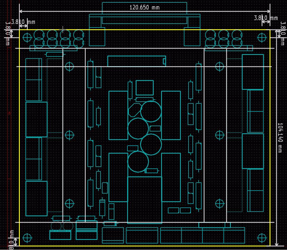
6 Board Dimensions
A4988 Stepper Motor Driver Carrier with Voltage Regulators
 1 of 6 12/2/2011 6:37 PM A4988 Stepper Motor Driver Carrier with Voltage Regulators Pololu item #: 1183 26 in stock Price break Unit price (US$) 1 19.95 10 17.95 100 13.97 Quantity: backorders allowed
A4988 Stepper Motor Driver Carrier
 A4988 Stepper Motor Driver Carrier A4983/A4988 stepper motor driver carrier with dimensions. Overview This product is a carrier board or breakout board for Allegro s A4988 DMOS Microstepping Driver with
A4988 Stepper Motor Driver Carrier, Black Edition
 A4988 Stepper Motor Driver Carrier, Black Edition A4988 stepper motor driver carrier, Black Edition, bottom view with dimensions. Overview This product is a carrier board or breakout board for Allegro
LCMM024: DRV8825 Stepper Motor Driver Carrier,
 LCMM024: DRV8825 Stepper Motor Driver Carrier, High Current The DRV8825 stepper motor driver carrier is a breakout board for TI s DRV8825 microstepping bipolar stepper motor driver. The module has a pinout
User Guide for 4 axis TB6560 driver board
 User Guide for 4 axis TB6560 driver board Product Features: Toshiba TB6560AHQ chip - High power, maximum 3.5A drive current chipset! 1-1/16 microstep setting - Higher accuracy and smoother operation than
User Guide for 3 axis TB6560 driver boar d
 User Guide for 3 axis TB6560 driver boar d Product Features: Toshiba TB6560AHQ chip - High power, maximum 3.5A drive current chipset! 1-1/16 microstep setting - Higher accuracy and smoother operation than
XS-3525/8S-3. Standard Pinout Information. Single Supply (v1s) XØ YØ ZØ
 XØ YØ ZØ") XS-3525/8S-3 Single Supply (v1s) Standard Pinout Information XØ YØ ZØ The 26 pin header is configured to allow easy connection via ribbon cable to an IDC DB-25 connector. This facilitates direct connection
XS-3525/8S-3 Single Supply (v1s) Standard Pinout Information XØ YØ ZØ The 26 pin header is configured to allow easy connection via ribbon cable to an IDC DB-25 connector. This facilitates direct connection
User Guide for 4 axis TB6560 driver board. *Important Note*: Please strictly follow the setting photos for configuration
 User Guide for 4 axis TB6560 driver board Settings of MACH3 *Important Note*: Please strictly follow the setting photos for configuration in Mach3! Fig.1 Open MACH3 software, select mach3mill, and then
CHANGZHOU WANTAI ELECTRICAL APPLIANCE CO., LTD. User Guide for 3 axis TB6560 driver board
 CHANGZHOU WANTAI ELECTRICAL APPLIANCE CO., LTD Product Features: User Guide for 3 axis TB6560 driver board Toshiba TB6560AHQ chip - High power, maximum 3.5A drive current chipset 1-1/16 microstep setting
MP6500 Stepper Motor Driver, Digital Current Control
 This breakout board for the MPS MP6500 micro stepping bipolar stepper motor driver is Pololu s latest stepper motor driver. The module has a pinout and interface that are very similar to that of our popular
4-Axis TB6560 CNC Driver Board Users Manual. 1.1 Scope General Description Photo of 4-AXIS CNC Board Key Features...
 Content 4-Axis TB6560 CNC Driver Board Users Manual 1. General Information... 2 1.1 Scope... 2 1.2 General Description... 2 2. Descriptions of 4-AXIS CNC Board... 2 2.1 Photo of 4-AXIS CNC Board... 2 2.2
User's Manual. For ST-6560V3. Version All Rights Reserved
 User's Manual For ST-6560V3 Version 2.0 2016.08.25 All Rights Reserved 1. Key Features Toshiba TB6560AHQ chip - High power, maximum current 3.5A Resolution 1, 1/2, 1/8, 1/16 micro stepping output Working
MSD980 Microstepping Drive
 MSD980 Microstepping Drive Introduction MSD980 is a high-performance microstepping drive based on most advanced technology in the world today. It is suitable for driving any 2-phase and 4-phase hybrid
Three Axis CNC Driver Users Manual
 Three Axis CNC Driver Users Manual Revision 1.2 June 14. 2007 1 Content 1. GENERAL INFORMATION... 3 1.1. Scope... 3 1.2. General Description... 3 1.3. Features... 3 2. Descriptions of 3-AXIS CNC Board...
3-Axis Stepper Drive Datasheet MX3660
 3-Axis Stepper Drive Datasheet MX3660 3-Axis Stepper Drive + Breakout Board, 20-60VDC, 6A Peak Version 0.0.2 http://www.leadshine.com Features Three individual stepper drive boards Suitable for NEMA17
ADVANCED MICRO SYSTEMS
 Overview... 3 Included in the Box:... 3 Pinout... 4 Installation... 5 Power Supply... 6 Stepping Motors... 7 DIP Switch (JP1) Location... 8 Setting the Output Current (JP1)... 8 Microstep Resolution (JP1)...
Stepper Drive Setup Guide
 MACHMOTION Stepper Drive Setup Guide 1/21/2011 Everything you need to know to connect your stepper motors to the MachMotion stepper drives. MachMotion Version 1.0.1 2 P a g e Copyright 2011, MachMotion.com
MSD325 Microstepping Drive
 MSD325 Microstepping Drive Introduction MSD325 is a very small size microstepping drive based on most advanced technology in the world today. It is suitable for driving any 2-phase and 4-phase hybrid stepper
USER S MANUAL. CNC Stepper Motor Control Box CS3EA4-1 Rev. 1
 USER S MANUAL CNC Stepper Motor Control Box CS3EA4-1 Rev. 1 April, 2012 USER'S MANUAL TABLE OF CONTENTS Page # Contents 1.0 FEATURES... 2 2.0 SPECIFICATIONS... 3 3.0 SYSTEM REQUIREMENTS... 3 4.0 WARNING...
Hardware Manual CNC760
 Hardware Manual CNC760 Revision 3 6 December, 2017 Released Copyright 2017 by Eding CNC History: Revision Date Author 1 22-5-2017 AB 2 23-6-2017 AB 3 6-12-2017 AB Revision overview: Revision Remarks 1
CNC Shield Guide V
 CNC Shield Guide V1.0 12 2018 Maker Group Global LLC 2018 Safety Statement The author of this document is not liable or responsible for any accidents, injuries, equipment damage, property damage, loss
SDM / 4 Phase Stepper Drive Module. Compact Size & High Power Density, 20-60VDC, 6A Peak. Version 1.0
 SDM660 2 / 4 Phase Stepper Drive Module Compact Size & High Power Density, 20-60VDC, 6A Peak Version 1.0 http://www.leadshine.com / http://www.leadshineusa.com 2013 Leadshine Technology Co., Ltd. 3/F,
DMX-K-DRV. Integrated Step Motor Driver + (Basic Controller) Manual
 Manual") DMX-K-DRV Integrated Step Motor Driver + (Basic Controller) Manual Table of Contents 1. Introduction... 4 Features... 4 2. Part Numbering Scheme... 5 3. Electrical and Thermal Specifications... 6 Power
DMX-K-DRV Integrated Step Motor Driver + (Basic Controller) Manual Table of Contents 1. Introduction... 4 Features... 4 2. Part Numbering Scheme... 5 3. Electrical and Thermal Specifications... 6 Power
IO3-R2 BREAKOUT BOARD
 IO3-R2 BREAKOUT BOARD DESCRIPTION Breakout board IO3-R2 (Revision R2) has digital buffer for STEP/DIR/ENA command signals and as such it is particularly suitable for the connection up to 4 microstep drives
Hardware Installation Manual MX Axis Stepper Drive with Breakout Board & I/O s
 Hardware Installation Manual MX3660 3-Axis Stepper Drive with Breakout Board & I/O s Version 1.0 11 / 2013 Hardware Manual for MX3660 3-Axis Stepper Drive with Breakout Board & I/O s ii Notice Read this
Thank you for choosing our company's products, the use of CNC products better and faster for you, please read this manual
 HY-TB3DV-HH(HL) 3-axis drive board manual Product Link: http://www.thanksbuyer.com/cnc-very-professiona l-3-axis-3-5a-tb6560-stepping-motor-driver-cont roller-lcd-display-cnc-router-24898 Thank you for
Overview Included in the Box: Pinout Installation Power Supply Stepping Motors DIP Switch (JP1) Location...
 Location...") DRV7 USERS GUIDE Overview... 3 Included in the Box:... 4 Pinout... 4 Installation... 5 Power Supply... 6 Stepping Motors... 8 DIP Switch (JP1) Location... 9 Setting the Output Current (JP1)... 9 Microstep
DRV7 USERS GUIDE Overview... 3 Included in the Box:... 4 Pinout... 4 Installation... 5 Power Supply... 6 Stepping Motors... 8 DIP Switch (JP1) Location... 9 Setting the Output Current (JP1)... 9 Microstep
Novusun Controller Wiring and MACH3 Software Setup
 Novusun Controller Wiring and MACH3 Software Setup V1.0 01 2019 Open Source Mechatronics LTD 2019 Safety Statement The author of this document is not liable or responsible for any accidents, injuries,
USER S MANUAL. CNC Servo Stepper Motor Control Box CH4EV12-1 Rev. 1
 USER S MANUAL CNC Servo Stepper Motor Control Box CH4EV12-1 Rev. 1 January, 2013 i USER'S MANUAL TABLE OF CONTENTS Page # Contents 1.0 FEATURES... 1 2.0 SPECIFICATIONS... 2 3.0 SYSTEM REQUIREMENTS... 2
Datasheet MX Axis Stepper Drive with Breakout Board & I/O s. Version1.0
 Datasheet MX3660 3-Axis Stepper Drive with Breakout Board & I/O s Version1.0 1. Features Power up to 3 stepper motors of NEMA 17, 23, 24, or 34 Sophisticated stepper motor control based on latest DSP technology
G540 4-AXIS DRIVE REV 4: MAY 28, 2010
 Thank you for choosing to purchase the G540 4-Axis Drive System. If you are dissatisfied with it for any reason at all within two weeks of its purchase date, you may return it for a full refund provided
G540 MANUAL MULTIAXIS STEP MOTOR DRIVE
 G540 MANUAL MULTIAXIS STEP MOTOR DRIVE PRODUCT DIMENSIONS PHYSICAL AND ELECTRICAL RATINGS Minimum Maximum Units Supply Voltage 18 50 VDC Motor Current 0 3.5 A Power Dissipation 1 13 W Short Circuit Trip
Draft. CNC Controller Datasheet. 1 Features. 2 Applications
 1 Features 4-axis stepper motor control 2 general purpose 15 amp switched load outputs 12-36 VDC power supply Up to 15 amps output current. Plug compatible with standard Mean Well power supply Up to 6
Preliminary Datasheet MX Axis Stepper Drive with Breakout Board & I/O s. Preliminary V1.0
 Preliminary Datasheet MX4660 4-Axis Stepper Drive with Breakout Board & I/O s Preliminary V1.0 Features Power up to 4 stepper motors of NEMA 17, 23, 24, or 34 Sophisticated stepper motor control based
G540 User Manual. Date Modified: March 5, 2012 Page 1 of 10
 G540 User Manual Date Modified: March 5, 2012 Page 1 of 10 DIMENSIONS PHYSICAL AND ELECTRICAL RATINGS Minimum Maximum Units Supply Voltage 18 50 VDC Motor Current 0 3.5 A Power Dissipation 1 13 W Short
HY-TB5 CNC Series Manual five axis
 HY-TB5 CNC Series Manual ------ five axis Thank you for choosing our products better and faster for you to use NC products, please read this manual, make sure the pump is started before the water-cooled
Stepper. Manuals about stepper drives. Stepper Drive Wiring Diagram - Apollo Stepper Drive Setup Guide
 Stepper Manuals about stepper drives Stepper Drive Wiring Diagram - Apollo Stepper Drive Setup Guide Stepper Drive Wiring Diagram - Apollo Cont rol Connect or Signal PUL+ PUL DIR+ DIR EN+ EN Color Brown/White
TECHNICAL REFERENCE BSD V-3A Bipolar Stepper Driver
 TECHNICAL REFERENCE BSD 3630 36V-3A Bipolar Stepper Driver Contents Chapter 1 Safety Precautions.. 3 Chapter 2 Drive Overview...4 2.1 Key Features...4 2.2 Drive Description...4 2.3 Applications. 4 Chapter
CNCtak.com CNCtak.com CNCtak.com
 1 User Guide for 4 axis TB6560 driver board เป นส นค าจากประเทศจ น ท ม จ ดเด นของ DRIVER BOARD ของ Toshiba TB6560AHQ chip ตามรายละเอ ยด Block Diagram Toshiba TB6560AHQ chip Product Features: 1.Toshiba
Stepper 6 click. PID: MIKROE 3214 Weight: 26 g
 Stepper 6 click PID: MIKROE 3214 Weight: 26 g Stepper 6 click is the complete integrated bipolar step motor driver solution. It comes with the abundance of features that allow silent operation and optimal
Blue Point Engineering
 Overview DMX Duo driver board allows 2 Unipolar motors and 1 open collector output driver to be controlled from a DMX512 network. he board provides 2 independent motor drives, 1 external load driver and
PP-BOB2-V2.0 PARALLEL PORT BREAKOUT BOARD
 PP-BOB2-V2 PARALLEL PORT BREAKOUT BOARD Document: Operation Manual Document #: T18 Document Rev: 1.0 Product: PP-BOB2-V2.0 Product Rev: 1.0 Created: October, 2015 THIS MANUAL CONTAINS INFORMATION FOR INSTALLING
1. Key Features. 2. Photo of 4-AXIS CNC Board
 This document describes the basic functionality and the electrical specifications of StepperOnline s Four Axis TB6600 CNC Driver Board. 1. Key Features Supports MACH3, KCAM4, EMC2 etc Can drive four channels
2L415B High Performance-Cost ratio 2-phase Microstepping Driver
 User s Manual High Performance-Cost ratio 2-phase Microstepping Driver VER 2.0 Appreciate your selection of MotionKing TM driver. To make full use of its versatile performance, please read this manual
BUILD: ARDUINO NANO + NEMA17 BIPOLAR STEPPER 12V 0.4A + EASYDRIVER
 BOARD OPTION HW203 DRIVER BOARD The EASYDRIVER v44 driver board which can supply up to 750mA maximum current (typically 500mA), thus is able to driver stepper motors that require more current and hence
Stepper motor driver HEM-545 last change:
 Documentation for Stepper motor driver HEM-545 last change: 16.03.2011 Functional description HEM-545 is a one channel motor driver for 2-phase stepping motors with pulse and direction interface. Motor
HY-TB3DV-S intelligent 3-axis drive board manual
 HY-TB3DV-S intelligent 3-axis drive board manual Thank you for choosing our company's products, the use of CNC products better and faster for you, please read this manuai Features: Features 1: integrated
R325P Single Axis Driver
 R325P Single Axis Driver User Manual And Commands Guide Version 1.3 Thank you for purchasing the R325P Single-Axis Step & Direction Driver. This product is warranted to be free of manufacturing defects
USER S MANUAL. C32- DUAL PORT MULTIFUNCTION CNC BOARD Rev. 4
 USER S MANUAL C32- DUAL PORT MULTIFUNCTION CNC BOARD Rev. 4 August, 2012 USER'S MANUAL TABLE OF CONTENTS Page # 1.0 FEATURES... 1-1 2.0 SPECIFICATIONS... 2-3 3.0 BOARD DESCRIPTION... 3-4 4.0 FUNCTIONAL
Datasheet MX Axis Stepper Drive with Breakout Board & I/O s. Version
 Datasheet MX3660 3-Axis Stepper Drive with Breakout Board & I/O s Version 1.1 http://www.leadshine.com http://www.leadshineusa.com 2013 Leadshine Technology Co., Ltd. Notice This manual is not for use
Users Manual. For P808. High Performance Microstepping Driver
 Users Manual For P808 High Performance Microstepping Driver Thank you for purchasing the Astrosyn P808 drive. Please read this manual thoroughly before installing and operating the driver, and always keep
MD3. Microstepping Motor Driver Page 1 of 7. Description. Software. Mechanical Drawing. Features
 Page 1 of 7 The MD3 is a stepper motor driver with an integrated motion controller that is capable of driving size 14 to 42 stepper motors from 2 to 256 microsteps per step. Peak motor currents are selectable
1. Key Features. 2. Photo of 4-AXIS CNC Board
 This document describes the basic functionality and the electrical specifications of StepperOnline s Four Axis TB6600 CNC Driver Board. 1. Key Features Supports MACH3, KCAM4, EMC2 etc Can drive four channels
Me Stepper Driver. Overview
 Me Stepper Driver Overview The Me Stepper Motor Driver module is designed to precisely drive the bipolar stepper motor. When pulse signals are input into the stepper motor, it rotates step by step. For
PP-BOB2-V1.0 PARALLEL PORT BREAKOUT BOARD
 PP-BOB2-v1 PARALLEL PORT BREAKOUT BOARD Document: Operation Manual Document #: T17 Document Rev: 2.0 Product: PP-BOB2-v1.0 Product Rev: 1.0 Created: March, 2013 Updated: Dec, 2014 THIS MANUAL CONTAINS
Profi4 Main Board Manual
 Profi4 Main Board Manual A. Scope of application It is used to run the signal processing of the host computer ( LPT port ), with MACH 3 CNC system software, and the peripheral machine dynamic electrical.
Stepper Driver. STP-M111G/H User Manual TPM. Version: V D25. To properly use the product, read this manual thoroughly is necessary.
 Stepper Driver STP-M111G/H User Manual Version: V1.1 2015D25 To properly use the product, read this manual thoroughly is necessary. Part No.: 81-00STP10-010 1 Revision History Date Revision Description
MK5 5-Axis Controller
 MK5 5-Axis Controller Technical Reference Manual PCB Rev 1.0 2010 SOC Robotics, Inc. 1 Manual Rev 0.91 Introduction The MK5 is a 5-Axis breakout board that accepts the MM120, MM130, MM133 or MM220 stepper
RoboClaw 120A/160A/200A Dual Channel Motor Controller
 RoboClaw 2x160A, 34VDC Dual Channel RoboClaw 2x120AHV, 60VDC Dual Channel RoboClaw 2x160AHV, 60VDC Dual Channel RoboClaw 2x200AHV, 60VDC Dual Channel Brushed DC Motor Controllers Version 2.1 (c) 2016 Ion
Routout CNC 3 Axis Plug & Play Controller Data Sheet Version 1.1
 Routout CNC 3 Axis Plug & Play Controller Data Sheet Version 1.1 The Routout CNC 3 Axis stepper motor drive box has many uses including for CNC retrofitting / robot control or driving you own CNC machine.
C3 INDEX PULSE BOARD Rev. 6
 C3 INDEX PULSE BOARD Rev. 6 User manual Rev. 1 Fig. 1. C3 Index Pulse Board 1. Overview. This card provides easy way of capturing the pulse signal from photo-transistor and transmitting it to the parallel
HDBB Breakout board user s manual
 HDBB Breakout board user s manual The HDBB breakout board was designed to use with our Whale2(-T)*, Whale3, Mammut* and Dugong servo drives or with any other third party stepper or servo drives which using
Comprehensive support USB hot-swappable, USB connection at any time to monitor the state, Mach3 work
 USB motion control card installation manual The card features: Supports all versions of Mach3, including the latest version of Mach3 R3.042.040. Supports all versions of Windows, including the latest version
USER S MANUAL. M16 POKEYS MOTION MOTHERBOARD Rev. 1.1 JUNE 2016.
 USER S MANUAL M16 POKEYS MOTION MOTHERBOARD Rev. 1.1 JUNE 2016. USER'S MANUAL TABLE OF CONTENTS Page # Contents 1.0 OVERVIEW... 1 2.0 FEATURES... 1 3.0 BOARD DESCRIPTION... 2 4.0 SPECIFICATIONS... 2 4.1
PoKeys57CNC and Mach4
 PoKeys57CNC and Mach4 Step by step guide - a.k.a. beginners guide Version: 13/12/2017 SAFETY INFORMATION This product is intended for integration by the user into a computer numerical control (CNC) machine.
Conect 121 Upgrade. Copyright 2013 Conqueror Design and Engineering Ltd.
 All rights reserved. Any dispute about the use of this software and/or hardware or of these terms and conditions shall be resolved or arbitrated under English Law. Manuals and accompanying documentation
Hardware Installation Manual MX Axis Stepper Drive with Breakout Board & I/O s
 Hardware Installation Manual MX3660 3-Axis Stepper Drive with Breakout Board & I/O s Version 1.1 12 / 2013 http://www.leadshine.com http://www.leadshineusa.com 2013 Leadshine Technology Co., Ltd. Hardware
Manual 5 Axis CNC Interface Breakout Board Model#-DB25-1R5AM
 Manual 5 Axis CNC Interface Breakout Board Read this manual carefully before making connections to the board. Store this manual away for further reference. Safety Notes: The electronics of the control
User Manual For DM332T. 2-Phase Digital Stepper Drive. Designed by StepperOnline. Manufactured by Leadshine
 User Manual For DM332T 2-Phase Digital Stepper Drive Designed by StepperOnline Manufactured by Leadshine #7 Zhongke Road, Jiangning, Nanjing, China T: 0086-2587156578 Web site: www.omc-stepperonline.com
EM705 2-phase Digital Stepper Drive
 EM705 2-phase Digital Stepper Drive 20-70V, 0.35-5A, Sensorless Stall Detection, Pre-Matching Motor Sensorless stall detection eliminates cost of feedback devices and time of cable connection Super-low
EM806 2-phase Digital Stepper Drive
 EM806 2-phase Digital Stepper Drive 24-80V, 0.35-6A, Sensorless Stall Detection, Pre-Matching Motor Sensorless stall detection eliminates cost of feedback devices and time of cable connection Super-low
TurboTaig Instruction Manual
 TurboTaig Instruction Manual Version: 2.2 Peter Homann 20 View St Highett 3190 homann@smartchat.net.au http://people.smartchat.net.au/~homann 1 Table of Contents Table of Contents... 2 Introduction...
3 axes stepper motor driver board. Slider SFX. Upgrading milling and turning machines to CNC machines by use of stepper motors. User guide SFX Page 1
 3 axes stepper motor driver board Slider SFX Upgrading milling and turning machines to CNC machines by use of stepper motors User guide SFX Page 1 Copyright Thorsten Ostermann, 2008 The present stepper
MEGATRONICS V3.0 QUICK START GUIDE
 MEGATRONICS V3.0 QUICK START GUIDE Thank you for purchasing the Megatronics v3.0! This small guide will answer the basic questions on how to connect the board to your 3D printer. For more information visit
Datasheet MX Axis Stepper Drive with Breakout Board & I/O s. Version
 Datasheet MX4660 4-Axis Stepper Drive with Breakout Board & I/O s Version 1.0 http://www.leadshine.com http://www.leadshineusa.com 2014 Leadshine Technology Co., Ltd. Notice This document is not for use
2. Computer system requirement Minimum configuration: 1) CPU:1GHz 2) Memory: 512MB 3) 500MB free disk space
 CPU:1GHz 2) Memory: 512MB 3) 500MB free disk space") 1. Products brief introduction USBCNCV4.0 is a high performance motion controller which based on PC software USBCNC control, the system can complete the conversion from G code to connect stepper motor
1. Products brief introduction USBCNCV4.0 is a high performance motion controller which based on PC software USBCNC control, the system can complete the conversion from G code to connect stepper motor
Datasheet-MA860 Stepper Motor Driver
 Datasheet-MA860 Stepper Motor Driver Introduction The MA860 is an economical micro-stepping driver based on patented technology of EDRIVE. It is suitable for driving 2-phase and 4-phase hybrid stepping
SmartFan Cirrus-9. Speed Control and Alarm for 4-Wire Fans CONTROL RESOURCES INCORPORATED. The driving force of motor control & electronics cooling.
 SmartFan Cirrus-9 Speed Control and larm for 4-Wire Fans The driving force of motor control & electronics cooling. P/N 4WR9C00-F DC Controls SmartFan Cirrus-9 is a digital fan speed control and alarm that
Hardware Installation Manual MX Axis Stepper Drive with Breakout Board & I/O s
 Hardware Installation Manual MX3660 3-Axis Stepper Drive with Breakout Board & I/O s Version 1.2 3 / 2015 http://www.leadshine.com http://www.leadshineusa.com 2015 Leadshine Technology Co., Ltd. Hardware
Thank you for choosing our products better and faster operational
 Aerospace TB3-axis drive board H-TB3DV-M Instructions Thank you for choosing our products better and faster operational numerical control for you, please read this manual Products Features 1 The maximum
Stepper motor driver Tiny-Step II Last change:
 Documentation for Stepper motor driver Tiny-Step II Last change: 24.9.2011 Functional description Tiny-Step II is a one channel motor driver for 2-phase stepping motors with pulse and direction interface.
RoboClaw 2x30A Dual Channel Motor Controller
 RoboClaw 2x30A, 34VDC Dual Channel Brushed DC Motor Controller Version 2.2 (c) 2016 Ion Motion Control. All Rights Reserved. Feature Overview: 60 Amps Peak Per Channel Channel Bridging Supported Dual Quadrature
Breakoutboard for ESS Smoothstepper
 Breakoutboard for ESS Smoothstepper Operation Manual All rights to these operating instructions remain with cnc-technics. Texts, information and illustrations of these operating instructions may not be
Logosol Supervisor I/O Controller CNC-SK-2310g2
 Features LS- compatible Safety Bus interface Safety Interlock functions 00% relay contact based Dual mechanical Relay based Power Supply control interface with safety line Spindle control interface with
LV8726TAGEVK Evaluation Kit User Guide
 LV8726TAGEVK Evaluation Kit User Guide 06/17/15 1 www.onsemi.com NOTICE TO CUSTOMERS The LV8726TA Evaluation Kit v0 is intended to be used for ENGINEERING DEVELOPMENT, DEMONSTRATION OR EVALUATION PURPOSES
DDUM CARD V1.0 Simple Description (English)
") DDUM CARD V1.0 Simple Description (English) Chapter 1 Overview 1.1 Simply Introduction 1.2 Requirements of Computer 1.3 Appearance and size of poduct 1.4 Notes and Cautions Chapter 2 Detailed Features
DDUM CARD V1.0 Simple Description (English) Chapter 1 Overview 1.1 Simply Introduction 1.2 Requirements of Computer 1.3 Appearance and size of poduct 1.4 Notes and Cautions Chapter 2 Detailed Features
BB-303 Manual Baseboard for TMCM-303
 BB-303 Manual Baseboard for TMCM-303 Trinamic Motion Control GmbH & Co. KG Sternstraße 67 D 20357 Hamburg, Germany http://www.trinamic.com BB-303 Manual (V1.04 / Jul 9th, 2007) 2 Contents 1 Features...
SmartFan Fusion-4. Speed Control and Alarm for DC Fans CONTROL RESOURCES INCORPORATED. The driving force of motor control & electronics cooling.
 SmartFan Fusion-4 Speed Control and Alarm for DC Fans The driving force of motor control & electronics cooling. P/N FUS300-F DC Controls SmartFan Fusion-4 is a digital fan speed control and alarm that
Integrated Stepper Drive & Motor
 SMD23 Integrated Stepper Drive & Motor Manual #: 940-0S050 User Manual AMCI Motion Control Products Important User Information The products and application data described in this manual are useful in a
DMX-K-DRV Integrated Step Motor Driver Manual
 Tu Sitio de Automatización! DMX-K-DRV Integrated Step Motor Driver Manual Table of Contents 1. Introduction... 4 2. Part Numbering Scheme... 4 3. Dimensions... 5 NEMA 11 DMX-K-DRV... 5 NEMA 17 DMX-K-DRV...
UNIVERSAL MOTION INTERFACE (UMI) ACCESSORY
 ACCESSORY") USER GUIDE UNIVERSAL MOTION INTERFACE (UMI) ACCESSORY Contents This user guide describes how to use the UMI-77, UMI-A, UMI-Flex, and UMI-Flex accessories. Introduction... What You Need to Get Started...
USER GUIDE UNIVERSAL MOTION INTERFACE (UMI) ACCESSORY Contents This user guide describes how to use the UMI-77, UMI-A, UMI-Flex, and UMI-Flex accessories. Introduction... What You Need to Get Started...
CONUCON Software. User Guide. for Linion, Dora and Fresadora. Dezember 2018 CONUCON Software v
 CONUCON Software User Guide for Linion, Dora and Fresadora Dezember 2018 CONUCON Software v181216 1 Contents 1.First Steps...2 Installing Drivers...2 Connecting...4 Graphical User Interface...4 Safety
TB6560 mach3 cnc Stepper Motor Controller operation instruction
 TB6560 mach3 cnc Stepper Motor Controller operation instruction CONTENT Ⅰ FEATURES OF TB6560...3 Ⅱ APPLICATIONS:...3 Ⅲ ELECTRICAL DRAWING...4 V DEFINITION ON PINS OF PARALLEL PORT...5 VI.ADJUSTING CURRENT
MaxStepper Serial Step and Direction Pulse Generator. User Manual
 MaxStepper Serial Step and Direction Pulse Generator User Manual 2007 Kellyware 9/20/2007 WWW.KELLYWARE.COM Table of Contents Table of Contents... 2 Parts List... 3 Key Features... 3 Introduction... 4
User Manual of 5Axis Breakout Board
 WWW.VALLDER.COM User Manual of 5Axis Breakout Board Safety Statement Vallder Ltd is not liable or responsible for any accidents, injuries, equipment damage, property damage, loss of money or loss of time
USER S MANUAL. C11S- MULTIFUNTCION CNC BOARD Rev. 1.2
 USER S MANUAL C11S- MULTIFUNTCION CNC BOARD Rev. 1.2 SEPTEMBER 2014 User s Manual Page i TABLE OF CONTENTS Page # 1. Overview... 1 2. Features... 1 3. Specifications... 3 4. BOARD DESCRIPTION... 4 5. Special
ACS Stepper Controller. Econo Stepper Controller
 ACS Stepper Controller & Econo Stepper Controller User's Manual June 22, 2005 6 2 3 3 E. S a w g ra s s R d S a ra s o ta, F L. 3 4 2 4 0 (9 4 1 )3 7 7-5 7 7 5 F A X(9 4 1 )3 7 8-4 2 2 6 www.acscontrol.com
TECHNICAL PRODUCT DATASHEET
 FORM-ENG-0018 REV A 06-02-03 ISO 9001 CERTIFIED Phone: (352) 629-5020 or 800-533-3569 Fax: (352)-629-2902 SUITABLE FOR EXTERNAL DISTRIBUTION TECHNICAL PRODUCT DATASHEET ES-Key Climate Control Module P/N
Manual. Model#-DB25M-3R6A. 6 Axis CNC Interface Breakout Board. Lastest update : Feb Store this manual away for further reference.
 Manual 6 Axis CNC Interface Breakout Board Model#-DB25M-3R6A Lastest update : Feb 2016 Read this manual carefully before making connections to the board. Store this manual away for further reference. Safety
MicrostepPLD Driver Manual Version 6/13/2006
 MicrostepPLD Driver Manual Version 6/13/2006 Embedded Acquisition Systems 2517 Cobden Street Sterling Heights, MI 48310 http://www.embeddedtronics.com email sales@embeddedtronics.com copyright 2003-2004