MTGW. Installation Guide. CAN-RS-485 BUS Gateway
|
|
|
- Hilda Underwood
- 6 years ago
- Views:
Transcription
1 MTGW EN Installation Guide CAN- BUS Gateway
2 MTGW Installation Instructions 1.0 Overview Trademarks Microsoft Windows 98/2000/XP are registered trademarks of Microsoft Corporation in the United States and other countries. 1.0 Overview 1.1 Multi-Tenant System (MTS) Overview MTS is a distributed security system for monitoring and controlling a large number of small sites. Examples include apartment and condominium complexes, retail plazas, office buildings, and educational and hospital campuses. A typical MTS installation consists of the following components: MTSW Security Station Software: MTSW is an application based on Microsoft Windows, installed on a PC and monitored by guard station personnel. MTR Communication Receiver: The MTR receives and handles alarm events from devices connected to the CAN bus. It monitors and reports CAN bus status and other system internal events, and interfaces with MTSW to synchronize system data. MTGW CAN Bus Gateway: The MTGW converts data back and forth from an format to a Controller Area Network (CAN) bus format. The system supports up to 100 MTGWs on each CAN bus line. The MTGW provides three loops that support a total of 120 devices spread across the three loops. Bus Devices: Refer to Table 1 for a list of supported devices. Table 1: MTS Bus Devices Device DS6R2 IUI-DS12R ICP-MT1-2 ICP-MT2-8 ICP-MT3-1 Description Six Zone Keypad Controller Twelve Zone Keypad Controller Single Zone Input Module Two Zone Input Module Eight Zone Input Module Eight Relay Output Module One Input/One Output Module CAN bus wiring requirements are as follows: CAN Bus Interface: Connect the CAN bus to the MTR Communication Receiver with at least 1.5 mm (16 AWG) shielded twisted-pair wire; maximum length: 2000 m (6500 ft). Buses 1-3: Use at least 1.0 mm (20 AWG) shielded twisted-pair wire for the bus; maximum length: 1200 m (3900 ft). bus wiring status is supervised. 1.2 MTS Device Address You must assign an address to each device in the system. The address consists of at least four segments. For example: : This segment identifies the number assigned to the MTR central receiver (1 to 99). 2: This segment identifies the CAN bus number occupied by the MTGW (1 or 2). 5 : This segment identifies the MTGW s CAN bus address (1 to 100). 3 : This segment identifies the device s address (1 to 120). 6 : This segment identifies the zone number of an input or output device connected to the device. To set the DIP switch address on this device, refer to Section 4.0 Setting DIP Switches on page MTGW Overview The MTGW CAN Bus Gateway is used in Bosch Security Systems, Inc. Multi-tenant Systems (MTS) to convert data sent over an Bus into a format usable by a Controller Area Network (CAN) bus, and to convert CAN bus data into a format usable by an. This data includes events that occur at devices attached to an and commands sent from the Multi-tenant Receiver (MTR) Central Receiver to the devices. The MTGW can buffer up to 64 events for conversion. It also monitors the connection status of the entire CAN and nodes. Each Multi-tenant Gateway (MTGW) has three separate buses. The MTGW has one RS-232 interface for upgrading firmware. 2 Bosch Security Systems, Inc. 4/08 F01U
3 . 2.0 Wiring Install the MTGW according to this document to avoid damage to the devices. Remove power to the MTGW before connecting or removing it. Perform a system test after the installation to verify that all functions work properly. MTGW Installation Instructions 2.0 Wiring One MTGW has three isolated bus terminal pairs. Each MTGW can support up to 120 devices, including the DS6R2 Keypad Controller, Single Zone Input Module, Eight Zone Input Module, IUI-DS12R Twelve Zone Keypad Controller, ICP-MT1-2 Two Zone Input Module, ICP-MT2-8 Eight Relay Output Module, and ICP-MT3-1 One Input/One Output Module. Divide the devices as evenly as possible across all three terminals for improved system loading and fault tolerance. Refer to Table 2 and Figure 1. Table 2: Power and Wiring Specifications* Power Supply Accessory Output Power Battery Input 18.5 VAC provided by transformer (included) 500 ma maximum 12 V battery connectors; chargeable; battery status is monitored Recommended battery: 12 VDC, 7 Ah sealed lead-acid (at least 12 V 3 Ah) Wiring CAN bus interface Connect the CAN Bus to the MTR Central Receiver with at least 1.5 mm (16 AWG) shielded twisted-pair wire; maximum length, 2000 m (6500 ft). Bus 1 Bus 2 Bus 3 * Refer to Table 3 on page 4 for detailed specifications. 1.0 mm (20 AWG) shielded twisted-pair wire for the bus. Maximum length, 1200 m (3900 ft). bus wiring status is monitored. Figure 1: System Diagram CAN 1 CAN 2 MTR Central Receiver MTGW MTGW 1 DS6R DS6R2 DS6R2 DS6R2 DS6R2 DS6R2 Bosch Security Systems, Inc. 4/08 F01U

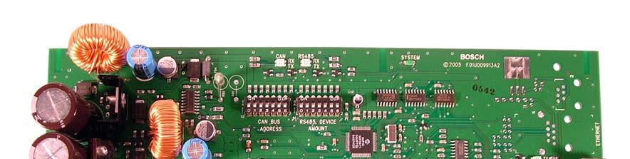
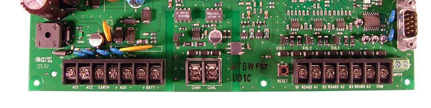
4 MTGW Installation Instructions 2.0 Wiring Figure 2: MTGW Circuit Board and Interface Description Table 3: MTGW Description and Specifications Figure 2 Callouts Callout Description Description and Specifications 1 CAN BUS ADDRESS DIP switch address of the MTGW on the CAN bus (refer to Section 4.0 Setting DIP Switches on page 5). 2 DEVICE AMOUNT 3 RS-232 programming port DIP switch addressing for the amount of installed devices (refer to Section 4.0 Setting DIP Switches on page 5). RS-232 programming port; use to upgrade MTR firmware (refer to Section 3.0 MTGW Firmware Upgrade on page 5). 4 TAMPER Tamper switch terminals (2); connect to tamper switch wires in the MTGW s enclosure 5 COM Common ground (optional) 6 A3 and B3 Bus 3 Use at least 1.0 mm (20 AWG) 7 A2 and B2 Bus 2 (shielded* twisted-pair wire for the bus; maximum length 8 A1 and B1 Bus m (3900 ft). 9 RESET Reset Button bus wiring status is monitored. 10 CANH and CANL CAN bus interface Connect the CAN Bus to the MTR Central Receiver with at least 1.5 mm (16 AWG) shielded* twisted-pair wire; maximum length 2000 m (6500 ft). 11 EOL jumper CAN bus EOL jumper. This jumper must be closed on the last MTGW on the bus. Use standard CAN or repeaters to increase the wiring run for both the CAN Bus and bus. Multirepeaters can be used in one system. Avoid branch wiring (T-taps or star topology) the CAN and bus. 12 BATT + and 12 V battery connectors; chargeable; battery status is monitored Recommended battery: 12 VDC, 7 Ah sealed lead-acid (at least 12 VDC 3 Ah) 13 AUX + and Accessory output power 500 ma maximum 14 EARTH Earth ground MTGW Current Draw: Output: 15 AC1 and AC2 Power Supply: Input 18.5 VAC provided by transformer (included) * To terminate shielded twisted-pair wire, ground the bus by connecting the wire to the MTGW s COM terminal. 100 ma standby Up to V ± 5% when using both the battery charging and auxiliary outputs 13 VDC ± 5% for battery charging and auxiliary power 4 Bosch Security Systems, Inc. 4/08 F01U
5 MTGW Installation Instructions 3.0 MTGW Firmware Upgrade. 3.0 MTGW Firmware Upgrade Upgrade the MTGW firmware using MTRAM, a Windows PC application software with a Chinese and English interface. It is provided as a separate tool in the Multi-tenant Software (MTSW) CD (P/N: F01U011231). 1. Connect the PC COM port to the RS-232 port, Figure 2, Item 3 on page 4 using an RS-232 cable. The cable is included with the MTR. 2. Insert the MTSW CD into a PC that supports Windows 98/2000/XP. 3. Select System Management Firmware Utilities Manual Upgrade Wizard, then select MTGW and follow the software s instructions to finish the firmware upgrade. MTRAM opens automatically and guides you through the installation. 4. Press the RESET button on MTGW to start the upgrade. Refer to Figure 2, Item 9 on page Setting DIP Switches Setting a DIP switch to ON (up) equals the binary digit 1. Setting the DIP switch in a down (off) position equals the binary digit 0. DIP switches set the binary address according to the order of the switches 0, 1, 2, 3, 4, 5, 6. In Figure 3, the binary address is , which is address 006 (refer to Table 5 on page 6). Figure 3: Binary Address ON DIP CAN BUS ADDRESS is the address of the MTGW on the CAN bus. The DEVICE AMOUNT equals the number of devices connected. Refer to Figure 2, Items 1 and 2 on page 4. For each CAN Bus, you can connect up to 100 MTGWs. The highest binary address is , which corresponds to an address of 100. You can connect 120 devices. The highest binary amount for the Bus is , which corresponds to 120. Use Table 5 on page 6 to determine the appropriate address settings for the devices on your system. For example: Set the CAN BUS ADDRESS DIP switches as follows for an MTGW with the address of 10: Set the DEVICE AMOUNT DIP switches as follows for a total of 50 devices on all three buses: System Status Reapply power to the MTGW. Table 4 indicates the system status. Use this table during the System Tests to determine if the system is operating correctly. Table 4: System LED Status LED Name Status Description POWER Power indicator Off No power On Power on SYSTEM System indicator Steady green or LED off System trouble Flashes green at 1 sec intervals System normal CAN CAN Bus indicator Flashes red and green alternately CAN Bus normal Steady red or green LED CAN Bus trouble Bus indicator Flashes red and green alternately Bus normal Steady red or green Bus trouble Bosch Security Systems, Inc. 4/08 F01U
6 MTGW Installation Instructions 6.0 DIP Switch Addresses 6.0 DIP Switch Addresses Table 5: DIP Switch Addresses DIP Switch Number = DIP switch ON DIP Switch Number = DIP switch ON DIP Switch Number = DIP switch ON Address* Address* * The device s address. 1 CAN Bus device: The highest address is Device Amount: The highest address is 120 Address* 6 Bosch Security Systems, Inc. 4/08 F01U
7 . Notes MTGW Installation Instructions 5.0 System Status Bosch Security Systems, Inc. 4/08 F01U
8 Bosch Security Systems, Inc. 130 Perinton Parkway Fairport, NY Bosch Security Systems, Inc. F01U
EA500. Installation Instructions Transponder
 EA500 EN Installation Instructions Transponder EA500 Installation Instructions 1.0 Overview EN 2 1.0 Overview The EA500 Transponder is the Security Escort module that provides communications between the
ICP-SDI Installation Instructions. SDI Splitter
 ICP-SDI-9114 EN Installation Instructions SDI Splitter ICP-SDI-9114 Installation Instructions Listings and Approvals Listings and Approvals UL UL 65 Police Station Burglar Alarm Units and Systems UL 609
Control Panels B5512/B4512. en UL Installation Instructions
 Control Panels B551/B451 en UL Installation Instructions Control Panels Table of Contents en 3 Table of contents 1 Introduction 4 1.1 About documentation 4 1.1.1 Related documentation 4 1. Bosch Security
FPA-1000-V2 Network Cards FPE-1000-NE, FPE-1000-NF, and FPE-1000-NW
 FPA-1000-V2 Network Cards FPE-1000-NE, FPE-1000-NF, and FPE-1000-NW en Installation manual FPA-1000-V2 Network Cards Table of contents en 3 Table of contents 1 General Information 4 1.1 Safety 4 1.2 Network
Quick Start Installation Guide
 apc/l Quick Start Installation Guide Version A2 Document Part Number UM-201 May 2010 OVERVIEW The apc/l is an intelligent access control and alarm monitoring control panel which serves as a basic building
TAC I/NETTM 1284, 1280, Security Control Unit
 TAC I/NETTM The SCU () family of modular, stand-alone controllers are basic building blocks of the I/NET Seven Security Management System, and provide a flexible mix of door control and alarm monitoring
Control Panel. D9412GV4/D7412GV4/D7212GV4 v1.xx. Release Notes
 Control Panel D9412GV4/D7412GV4/D7212GV4 v1.xx en Release Notes Control Panel Table of contents en 3 Table of contents 1 Introduction 4 1.1 About documentation 4 1.1.1 Bosch Security Systems, Inc. product
SOFTWARE VERSION 3.10
 738PEP-03 SOFTWARE VERSION 3.10 HEXA PROGRAMMING: Addresses 000 to 043 and 300 to 527 are programmed using the Hexa Programming method. In this mode, you can enter any hexa-digit from 0-F where keys [1]
The Programmable 4-Way Relay Card is an optional peripheral unit that provides four individually programmable relay output circuits.
 Peripheral Relay The Programmable 4-Way Relay Card is an optional peripheral unit that provides four individually programmable relay output circuits. Up to 16 Cards can be connected to a multi-loop panel
Conettix ITS-D6682-INTL
 Conettix ITS-D6682-INTL EN Installation Guide Ethernet Network Adapter Conettix ITS-D6682-INTL Installation Guide Contents Contents 1.0 Introduction... 3 1.1 Network Interface... 3 1.2 Serial Interface...
PRT-RDS2 Standard 2 Reader Expander
 PRT-RDS2 Standard 2 Reader Expander Installation Manual CONTENTS Protégé System... Introduction... Reader Expander... Features... Reader Expander Specifications... Protégé System Management Suite... Protégé
CA-A480-A Elevator Controller. Reference & Installation Manual
 CA-A480-A Elevator Controller Reference & Installation Manual TABLE OF CONTENTS INTRODUCTION.................................................................. 4 Introduction.............................................................................................
Conettix ITS-D6686-UL PRELIMINARY. Installation Guide. Ethernet Network Adapter
 Conettix ITS-D6686-UL EN Installation Guide Ethernet Network Adapter Conettix ITS-D6686-UL Installation Guide Contents Contents 1.0 Introduction... 3 1.1 Network Interface... 3 1.2 Serial Interface...
Conettix ITS-D6686-UL
 Conettix ITS-D6686-UL EN Installation Guide Ethernet Network Adapter Conettix ITS-D6686-UL Installation Guide Contents Contents 1.0 Introduction... 3 1.1 Network Interface... 3 1.2 Serial Interface...
1 Description. 2 Specifications. Product Installation Document. Honeywell 12 Clintonville Road Northford, CT
 Honeywell 12 Clintonville Road Northford, CT 06472 http://www.honeywellpower.com HP600ULACM4CB HP600ULACM8CB Access Control Power Supply/Charger with Power Distribution Controller PN 52395:A 1/05/06 ECN
Conettix ITS-D6682-UL
 Conettix ITS-D6682-UL EN Installation Guide Ethernet Network Adapter Conettix ITS-D6682-UL Installation Guide Contents Contents 1.0 Introduction...3 1.1 Network Interface... 3 1.2 Serial Interface... 3
NetworX Series. NX-507E RELAY EXPANDER NX-508E OUTPUT EXPANDER Installation and Startup
 NetworX Series NX-0E RELAY EXPANDER NX-0E OUTPUT EXPANDER Installation and Startup NX-0E / NX-0E AUXILIARY MODULES TABLE OF CONTENTS I. GENERAL DESCRIPTION... II. WIRING INFORMATION... III. NX-0E TERMINAL
D1265. Installation Guide. Touchscreen Keypad
 D1265 EN Installation Guide Touchscreen Keypad D1265 Installation Guide 1.0 Introduction Contents 1.0 Introduction...3 1.1 Overview...3 1.2 Graphical Buttons...3 1.3 Audible Tones...4 1.4 Supervision...4
Conettix ITS-D6686-INTL
 Conettix ITS-D6686-INTL EN Installation Guide Ethernet Network Adapter Conettix ITS-D6686-INTL Installation Guide Contents Contents 1.0 Introduction... 3 1.1 Network Interface... 3 1.2 Serial Interface...
Enclosures AE1/AE3. Installation Guide
 Enclosures AE1/AE3 en Installation Guide Enclosures Safety en 3 1 Safety Notice! Do not flush mount! Regulatory agency requirements prohibit flush mounting the enclosures.! Caution! Ensure the enclosure
NetworX Series. NX-507E RELAY EXPANDER NX-508E OUTPUT EXPANDER Installation and Startup
 NetworX Series NX-0E RELAY EXPANDER NX-0E OUTPUT EXPANDER Installation and Startup NX-0E / NX-0E AUXILIARY MODULES TABLE OF CONTENTS I. GENERAL DESCRIPTION... II. WIRING INFORMATION... III. NX-0E TERMINAL
Quick Start Installation Guide
 RM-DCM-2 Quick Start Installation Guide Version G0 Document Part Number UM-215 May 2010 OVERVIEW The RM-DCM-2 is a UL294 Listed and UL1076 Listed door control module that includes the RM-4E Reader Module
Installation Manual GENERAL DESCRIPTION...2 WIRING INFORMATION FOR NX-507 AND NX NX-507 TERMINAL DESCRIPTION...3 NX-507 DRAWING...
 NX-0 RELAY EXPANDER NX-0 OUTPUT EXPANDER Installation Manual GENERAL DESCRIPTION... WIRING INFORMATION FOR NX-0 AND NX-0... NX-0 TERMINAL DESCRIPTION... NX-0 DRAWING... NX-0 TERMINAL DESCRIPTION... NX-0
Universal Expander Module INSTALLATION MANUAL. Overview. Electrical Specifications
 12 Universal Expander Module. Installation Notes. Revision 1.2 August. 2003. 1 Reporting Reporting with most Contact ID maps will treat the Mini Expander, Exp32 and Exp16 as the same. (With the exception
NX-2192E PINPOINT SYSTEM
 NX-9E PINPOINT SYSTEM INSTALLATION MANUAL TABLE OF CONTENTS. GENERAL DESCRIPTION.... INSTALLATION.... DEVICE ADDRESS CONFIGURATION.... TERMINAL DESCRIPTIONS.... WIRING DIAGRAM.... MAXIMUM NUMBER OF DEVICES
PRT-PX16 16 PGM Output Expander
 PRT-PX16 16 PGM Output Expander Installation Manual CONTENTS Protégé System Introduction... PGM Expander... Features... PGM Expander Specifications... Protégé System Management Suite... Protégé Modules...
Control Panel DS7400XiV4-EXP
 Control Panel DS7400XiV4-EXP Release Notes January 2005 Release Notes for Firmware Version 4.10 Trademarks Cobox is a trademark of Lantronix. 1.0 Remote Programming Compatibility Use RPS-INT L version
DX4020. Installation Guide. Network Interface Module
 DX4020 EN Installation Guide Network Interface Module DX4020 Installation Guide EN 2 Trademarks Microsoft - and Windows are either registered trademarks or trademarks of Microsoft Corporation in the United
Product Data Sheet. Hochiki 8 Way I/O Card. Features
 Hochiki 8 Way I/O Card Product Data Sheet Features The Mxp-019 is a stand-alone fire system peripheral based on the Hochiki ESP protocol for use with the Mx-4000 range of panels. The unit connects to the
UC-2000 Installation Manual Unicorn Computers Technology Limited
 UC2000 Installation Manual Copyright 2003. All rights reserved. Table of Contents Specifications 2 Enclosure for the UC2000 Controller 3 Unicorn Access Control System Configuration 4 UC2000 Controller
OPERATIONS MANUAL. n.form I/O Expander (RACK MOUNT) Document Number: Rev B
 Document Number: Rev B") OPERATIONS MANUAL n.form I/O Expander (RACK MOUNT) Document Number: 200-0009 Rev B table of contents INTRODUCTION FEATURES & CAPABILITIES 1 WIRING General I/O Configuring The System Using The System 4
OPERATIONS MANUAL n.form I/O Expander (RACK MOUNT) Document Number: 200-0009 Rev B table of contents INTRODUCTION FEATURES & CAPABILITIES 1 WIRING General I/O Configuring The System Using The System 4
Suprex RS-485 SPX-7500 Wired Reader-Extender
 Suprex RS-485 SPX-7500 Wired Reader-Extender Product Manual SPX-7500_MAN_181206 Cypress Integration Solutions 35 Years of Access Control Ingenuity CypressIntegration.com 2018 Cypress Computer Systems 1778
ATS125x 4-Door DGP Installation Manual
 GE Security ATS125x 4-Door DGP Installation Manual P/N 1065711 REV 1.0 ISS 27APR09 Copyright 2009 GE Security, Inc. This document may not be copied in whole or in part or otherwise reproduced without prior
Integriti 8-32 Zone LAN Expander Module Kit INSTALLATION MANUAL
 Revision 2.1 July. 2014 1 Integriti 8 32 Zone LAN Expander Module Kit P/N: 996005PCB&K For Rev. B PCB. INSTALLATION MANUAL Overview The Integriti 8 Zone Expander Module provides an additional 8 Zone inputs,
KP2000E/EM Series Style Keypad
 23852973 KP2000E/EM Series Style Keypad Installation and Programming Instructions Models KP2000EXX and KP2000EMXX Specifications Parameter Voltage Requirements Keypad Current Requirements (Max) Relay Contact
Model HM-535 Power Supply Installation and Service Instructions
 Model HM-535 Power Supply Installation and Service Instructions 430-535 0104 2004 Heritage MedCall, Inc SENTRY INSTALLATION & SERVICE INSTRUCTIONS POWER SUPPLY UNIT Model HM-535 IMPORTANT SAFETY INSTRUCTIONS
Click Save to return to the main Setup screen.
 ON-SITE Setup Guide Thank you for purchasing the ON-SITE. This guide will assist you in the setup of the system. You can call for FREE technical support to get help anytime at 757-258-0910. Please note,
PRO3200 Professional Modular Access Control Hardware
 PRO3200 Access Control Hardware As a part of the WIN-PAK software controlled hardware family the PRO3200 professional modular access control hardware is an advanced access control panel capable of providing
MR52 READER INTERFACE
 IN IN2 IN3 IN4 INPUTS IN5 IN6 IN7 IN8 C www.mercury-security.com 2355 MIRA MAR AVE. LONG BEACH, CA 9085-755, (562)986-905 FAX (562) 986-9205 MR52 READER INTERFACE Installation and Specifications: This
PRT-RDE2 Ethernet 2 Reader Expander
 PRT-RDE2 Ethernet 2 Reader Expander Installation Manual PUBLICATION INFORMATION This manual covers firmware versions 1.44 or higher of the Protégé 2 Reader Ethernet Expander when operating on hardware
SECURA KEY CARD ACCESS CONFIGURATION GUIDE Multi-Reader Systems with NOVA.16 (SK-MRCP) 16-Door Panel
 16-Door Panel") SECURA KEY CARD ACCESS CONFIGURATION GUIDE Multi-Reader Systems with (SK-MRCP) -Door Panel WITH RS- GATEWAY CONNECTED DIRECTLY TO A PC RS- GATEWAY POWER: EIGHT (8) SMART READERS EVENLY SPACED UP TO 000
SECURA KEY CARD ACCESS CONFIGURATION GUIDE Multi-Reader Systems with (SK-MRCP) -Door Panel WITH RS- GATEWAY CONNECTED DIRECTLY TO A PC RS- GATEWAY POWER: EIGHT (8) SMART READERS EVENLY SPACED UP TO 000
PRO2200 Professional Modular Access Control Hardware
 PRO2200 Access Control Hardware As a part of the WIN-PAK software controlled hardware family the PRO2200 professional modular access control hardware is an advanced access control panel capable of providing
genesis genesis Expander Unit - Technical Manual TECHNICAL MANUAL Australian Owned, Designed and Manufactured Expander Unit GEN-010
 Australian Owned, Designed and Manufactured Expander Unit GEN-010 Genesis Electronics Australia Pty Ltd www.genesiselectronics.com.au Distributed by: Genesis reserves the right to change or modify products
Cascade Configuration Tool
 Cascade Configuration Tool Version 1.0.10 Installation and Operations Manual 00-02-0724 01-25-11 Section 40 In order to consistently bring you the highest quality, full featured products, we reserve the
Conettix D6680. Installation Instructions. Ethernet Network Adapter
 Conettix D6680 EN Installation Instructions Ethernet Network Adapter Conettix D6680 Installation Instructions Trademarks Trademarks Microsoft Windows 98SE, Windows ME, Windows 2000, Windows NT, MS-DOS,
ACX Series. Access Controller for Ethernet
 Access Controller for Ethernet The controllers are the industry s most powerful all-in-one access controllers designed for both critical government and private sector security applications. 0 Features
Installation & Operation Guide
 Installation & Operation Guide (Shown with optional Override Board Cover) KMD-5831 Programmable Loop Controller PLC-28 Direct Digital Controller 902-019-04B 1 Introduction This section provides a brief
FPD-7024 Fire Alarm Control Panel Version 1.03
 FPD-7024 Fire Alarm Control Panel Version 1.03 Program Record Sheet Account Information: Account: Date: Name: Address: Panel Phone #: Contact Phone #: Contact Person: Comments: Panel Location: Notes: Program
E-Learning, DC drives DCS800 Hardware D5 D7, part 2
 E-Learning, DC drives DCS800 Hardware D5 D7, part 2 August 24, 2010 Slide 1 Objectives After completing this module, you will be familiar with: Function of POW-4 board Internal field exciter FEX-4 25 Function
Conettix Plug-in Communicator Interface
 Conettix Plug-in Communicator B450 en Installation and Operation Guide Conettix Plug-in Communicator Table of Contents en 3 Table of contents 1 Safety 4 2 Introduction 5 2.1 About documentation 5 2.2
INSTALLATION MANUAL. Table of Contents. General Description Position Dip Switch Settings Enrolling the NX216-E Expander...
 INSTALLATION MANUAL Table of Contents Page General Description... -Position Dip Switch Settings... Enrolling the NX-E Expander... Wiring the NX-E... Terminal Description... Wiring Diagram... Default Zone
Installation Instructions Model PSC-17C
 Installation Instructions Model PSC-17C 17 Amp Power Supply INTRODUCTION The Model PSC-17C from Siemens Industry, Inc. is a high current power supply that provides the Fire Alarm system (Sprachalarmsystem
N-1000-II. Installation & Programming Manual. Version rev. 2.0
 Installation & Programming Manual Version 8.0 September 1998 TD1062 rev. 2.0 Notices Fire Safety Notice: Never connect any card reader devices or locks to doors, gates or barriers without first consulting
INSOMNIAC CIA G-600 Gateway Installation Manual P/N CIA Revision 1.0 Date Code:
 INSOMNIAC CIA G-600 Gateway Installation Manual P/N CIA-675-001 Revision 1.0 Date Code: 1-1-2018 Table of Contents Table of Figures... 3 SPECIFICATIONS:... 4 INSTALLATION... 5 General:... 5 Physical Installation
EasyIO FC20 User Reference v1.3. EasyIO FC 20 DDC User Reference V1.3
 EasyIO FC 20 DDC User Reference V1.3 Document Change Log 1 st April 2013 Document created. 13 th July 2013 Software configurations added. 27 th Sept 2014 FC now support pulse input. 6 th June 2015 Serial
IPassan Installation guide
 IPassan Installation guide 1 Content 1 Overview... 3 1.1 Features... 3 1.2 Hardware... 3 1.2.1 s... 3 1.2.2 Extra modules... 5 1.3 IPassan manager... 7 2 Installation... 7 2.1... 8 2.1.1 Power supply...
TS0867 Four-Door & TS0869 Four-Lift Controller Installation Manual
 TS0867 Four-Door & TS0869 Four-Lift Controller Installation Manual P/N MAINST-867/869 REV 07 ISS 26NOV13 Copyright Trademarks and patents Manufacturer ACMA compliance Contact information 2013 UTC Fire
PRT-PSU-DIN-2A. Protege DIN Rail 2A Intelligent Power Supply. Installation Manual
 PRT-PSU-DIN-2A Protege DIN Rail 2A Intelligent Power Supply Installation Manual The specifications and descriptions of products and services contained in this document were correct at the time of printing.
Andover ContinuumTM Infinet II
 Andover ContinuumTM Infinet II The i80 Series controllers are designed for control of Air Handling Units, Roof Top Units, and other mechanical plant equipment. Features 0 Choose the i80 model with the
DAS 250L CONTROL COMMUNICATOR INSTALLATION MANUAL
 DAS 250L CONTROL COMMUNICATOR INSTALLATION MANUAL TABLE OF CONTENTS 1. GENERAL DESCRIPTION... P.2 2. STANDARD AND OPTIONAL PARTS LIST..... P.2 3. FEATURE DEFINITIONS... P.3 4. TERMINAL DRAWING AND SPECIAL
VertX. V100, V200 and V300. Installation Guide Barranca Parkway Irvine, CA USA. November Rev A.1
 15370 Barranca Parkway Irvine, CA 92618 USA VertX V100, V200 and V300 Installation Guide November 2011 6080-930 Rev A.1. Contents Introduction... 3 Parts List... 3 Product Specifications... 3 Cable Specifications...
Connecting a Cisco Input Module
 CHAPTER 4 Overview The optional Cisco Input Module (Figure 4-1) is attached to a Cisco Physical Access Gateway or Cisco Reader Module to provide additional connections for up to ten input devices. Each
Installing Sentor. Hardware Installation
 Remote base site monitoring and control Installing Sentor Hardware Installation Copyright 2000 Sentor Monitoring Systems Pty Ltd Contents: 1 Introduction... 1 2 Sentor GUI... 2 3 ST3000 Controller... 3
Amano (itrt) Intelligent Twin Reader Terminal INSTALLATION MANUAL
 Intelligent Twin Reader Terminal INSTALLATION MANUAL") MODEL NUMBER: XRT910-0-0-AC-XX XRT920-0-0-AC-XX AMANO itrt Amano (itrt) Intelligent Twin Reader Terminal INSTALLATION MANUAL SPECIFICATIONS Working Environment Plastic Housing... Power Designed to work
MODEL NUMBER: XRT910-0-0-AC-XX XRT920-0-0-AC-XX AMANO itrt Amano (itrt) Intelligent Twin Reader Terminal INSTALLATION MANUAL SPECIFICATIONS Working Environment Plastic Housing... Power Designed to work
EP-ELVCTL Elevator Control (NION-16C48M)
") EP-ELVCTL Elevator Control (NION-16C48M) Product Installation Document This document covers the procedures and specifications for installing the above listed unit and when appropriate, information regarding
EP-ELVCTL Elevator Control (NION-16C48M) Product Installation Document This document covers the procedures and specifications for installing the above listed unit and when appropriate, information regarding
Conettix Ethernet Communication Module
 Conettix Ethernet Communication B426 en Release Notes Conettix Ethernet Communication Table of Contents en 3 Table of contents 1 Introduction 4 1.1 Requirements 4 1.2 About documentation 5 2 Version 3.05
Andover ContinuumTM Infinet II
 Andover ContinuumTM Infinet II i2920 System Controllers The Andover Continuum Infinet II i2920 System Controller is designed to meet the needs of your most demanding control and monitoring applications
Diagnostics (Physical)
") DeviceNet Spanner Rugged, Fully Potted Stations IP 67 Protection Communicate Between s Connect Two DeviceNet Networks FDN-DN1 Electrical Operating Current: 125 ma from segment A, 30 ma from segment B Power
DeviceNet Spanner Rugged, Fully Potted Stations IP 67 Protection Communicate Between s Connect Two DeviceNet Networks FDN-DN1 Electrical Operating Current: 125 ma from segment A, 30 ma from segment B Power
PS-4100 POWER SUPPLY MANUAL
 PS-4100 POWER SUPPLY MANUAL Manual Part Number 180-0573 December 7, 2006 TABLE OF CONTENTS TITLE PAGE Table of Contents... 2 List Of Figures... 3 1. Introduction... 4 1.0. General... 4 1.1. Features...
Control Panel D9124. Release Notes for Version 7.00 March Introduction. 2.0 Requirements. 4.0 Previous Version 6.
 Control Panel Release for Version 7.00 March 2007 1.0 Introduction Firmware Update Kits (P/N: D9499-0700) are available for this product. Refer to the D9412G/D7412G Program Entry Guide (P/N: 47775D or
01348(N or G) MH** -- Material Handling (N or G) MH** -- Material Handling
 MH** -- Material Handling (N or G) MH** -- Material Handling") MATERIAL HANDLING MANIFOLDS WITH DeviceNet INTERFACE 01348(N or G) MH** -- Material Handling 01351(N or G) MH** -- Material Handling Note: N = NPT ports G = BSPP ports SOL 14 SOL 12 Station #3 SOL 14 SOL
MATERIAL HANDLING MANIFOLDS WITH DeviceNet INTERFACE 01348(N or G) MH** -- Material Handling 01351(N or G) MH** -- Material Handling Note: N = NPT ports G = BSPP ports SOL 14 SOL 12 Station #3 SOL 14 SOL
Vorne Industries. 2000S Series Serial Input Alphanumeric Display User's Manual
 Vorne Industries 2000S Series Serial Input Alphanumeric Display User's Manual 1445 Industrial Drive Itasca, IL 60143-1849 Telephone (630) 875-3600 Telefax (630) 875-3609 2000S Series Serial Input Alphanumeric
BACnet. b3810 Series Local Controllers
 BACnet b380 Series Local Controllers The Andover Continuum TM b380 series controllers are designed for control of Air Handling Units, Roof Top Units, and other mechanical plant equipment. 0 Features Choose
DIN-RAIL EXPANDER int-iors_en 10/14
 INT-IORS INT-ORS DIN-RAIL EXPANDER int-iors_en 10/14 The INT-IORS expander enables the system to be expanded by 8 programmable wired zones and 8 programmable wired outputs. The INT-ORS expander enables
1. Features. 2. Installation KNX INTEGRATION MODULE INT-KNX
 KNX INTEGRATION MODULE INT-KNX int-knx_en 09/11 The INT-KNX module integrates the INTEGRA alarm system with the KNX system, so the control panel can control the actuators connected to the KNX bus, and
Secured Series: Hub Plus Kit Single Door Controller Package Installation Manual
 Secured Series: Hub Plus Kit Single Door Controller Package Installation Manual This package is designed to simplify the connections to our Secured Series Hub Plus Controller. This will translate into
KT-300 DOOR CONTROLLER INSTALLATION MANUAL DN KANTECH SYSTEMS INC.
 KT-300 DOOR CONTROLLER INSTALLATION MANUAL NOVEMBER 1999 KT-300 - ENGLISH INSTALLATION MANUAL - INTRODUCTION Part of the DSC group, Kantech Systems Inc. embraces the group's corporate philosophy of providing
NETWORK CONCENTRATOR LINK. This equipment must only be installed and serviced by professional qualified personnel.
 Revised! see Protective Earthing Addendum cback NOTE: This equipment must only be installed and serviced by professional qualified personnel. The Network Concentrator Link is a fully self contained unit
ControlKeeper 4. General Information. Connecting Relay Loads. Installation Sheet. Getting Started. Power Supply Wiring. Mounting the Cabinet
 General Information ControlKeeper 4 Installation Sheet Model# CK4-120NO- Model# CK4-277NO The ControlKeeper-4 model is shipped in one package and is configured with either a 120V or a 277V transformer.
D1260/D1260B. Installation Guide. Keypads
 D1260/D1260B EN Installation Guide Keypads D1260/D1260B Installation Guide Trademarks Trademarks Microsoft, Windows, Windows NT are either registered trademarks or trademarks of Microsoft Corporation in
Conettix Plug-in Communicator Interface
 Conettix Plug-in Communicator B450 en Installation and Operation Guide Conettix Plug-in Communicator Table of Contents en 3 Table of contents 1 Safety 4 2 Introduction 5 2.1 About documentation 5 2.2
- NLS NAVIGATION LIGHT CONTROL
 Technical documentation - NLS 3000 - NAVIGATION LIGHT CONTROL For use on seagoing vessels Change status Version Date Author Checked Remark 0.1 07.08.2008 STO HN 1. Edition 0.2 29.09.2010 STO TK Changes
Multi-Point Gas Detection and Control System
 Multi-Point Gas Detection and Control System Specifications subject to change without notice. USA 40804 Page of 7 DESCRIPTION Wall mounted, microprocessor-based, multi-point, analog electronic control
KT-400 Ethernet Four-Door Controller
 KT-400 Ethernet Four-Door Controller Installation Manual DN2003-1202 V01.11 KT-400 Door Controller Installation Manual Table of contents Pre-Installation Information... 1 Copyright Information... 1 Safety
genesis Master Unit GEN-001 genesis Master Unit - Technical Manual TECHNICAL MANUAL Australian Owned, Designed and Manufactured
 Australian Owned, Designed and Manufactured Master Unit GEN-001 Genesis Electronics Australia Pty Ltd www.genesiselectronics.com.au Distributed by: Genesis reserves the right to change or modify products
Data Collecting Device. ProData. Operating Instructions. Dip Switches. Interface. Mode RS485- PT LON. Interface Analogue Input 0-20mA
 Data Collecting Device ProData Operating Instructions Digital Inputs 9-16 Dip Switches Modbus Address Dip Switches Interface Mode Supply Voltage 24V DC Relay Outputs Digital Inputs 1-8 LON Analogue Input
Expandable Power Systems
 Expandable Power Systems Installation Guide Models Include: Maximal11EV 12VDC @ 4A or 24VDC @ 3A. 12VDC @ 4A or 24VDC @ 3A. Maximal33EV 12VDC or 24VDC @ 6A. 12VDC or 24VDC @ 6A. Maximal37EV 24VDC @ 10A.
PW6000 Modular Access Control System PW6000 Intelligent Controllers and Modules
 Modular Access Control System The next generation of the PW-Series family improves on the existing PW technology to offer superior features and benefits. The PW-Series Modular Control System is an advanced
XT-9100 Technical Bulletin
 System 9100 Technical Manual 636.4 Technical Bulletins Section Technical Bulletin Issue Date 0896 XT-9100 Technical Bulletin XT-9100 Extension Module/XP-910x Expansion Modules Page 3 Introduction 3 SX
NetworX Series NX-216 Zone Expander Installation and Startup
 NetworX Series NX-216 Zone Expander Installation and Startup 2 2002 GE Interlogix All rights reserved. Printed in the United States of America. These instructions do not purport to cover all details or
Data sheet MK 20 GR. Customized solution or off-the-shelf: The choice is yours!
 Data sheet MK 20 GR Customized solution or off-the-shelf: The choice is yours! MK20-GR data sheet Looking for a quick and reliable solution? Then rely on our standard products: Our universal controls provide
CYPRESS " " EXP SPX Expansion interface! modules EXP-2000_MAN_0314
 CYPRESS EXP-2000 SPX Expansion interface! modules The EXP-2000 provides additional Door/Panel interface points to most SPX products. The EXP-2000 uses a local RS-485 network through an SPX gateway device.
Installation Instructions
 Alliance Arming Station AL-1111, AL-1116 1048520C September 2006 Copyright 2006, GE Security Inc. Introduction This is the GE Alliance Arming Station for models AL-1111 (four-line LCD) and AL-1116 (four-line
istar Pro Installation Guide
 istar Pro Installation Guide UM-241 Version A1 October 2010 istar Pro Installation Quick Start Guide System Components The istar Pro hardware components consist of: General Controller Module (GCM) A general
CS XL XM. EcoSystem Bus Supply
 EcoSystem An EcoSystem lighting network containing more than one ballast, module, or driver requires an EcoSystem. This supply powers one or two independent EcoSystem buses with up to 64 ballasts or ballast
4100/4120-Series Class A / Class B Zone Modules Installation Instructions
 4100/4120-Series Class A / Class B Zone Modules Installation Instructions Introduction This publication describes the installation procedure for the following modules. Model Description Required Back Box
I-7570 Serial To HART Converter
 I-7570 Serial To HART Converter User s Manual Warranty All products manufactured by ICP DAS are under warranty regarding defective materials for a period of one year from the date of delivery to the original
CDN502 HIGH DENSITY I/O ADAPTER USER GUIDE
 CDN502 HIGH DENSITY I/O ADAPTER USER GUIDE 13050201 (c) Copyright DIP Inc., 1996 DIP Inc. P.O. Box 9550 MORENO VALLEY, CA 92303 714-924-1730 CONTENTS DN502 PRODUCT OVERVIEW 1 DN502 INSTALLATION 1 POWER
Security Management System by Diebold, Inc. LINX System Hardware Installation Guide
 Security Management System by Diebold, Inc. LINX System Hardware Installation Guide INSTALLATION GUIDE LINX Integrated Security System WSD 2000 Weatherized Status Display Table of Contents Introduction
VISTA 12a / 48a TECHNICAL TRAINING. The Best in Security plus Everyday Convenience & Control
 VISTA 12a / 48a TECHNICAL TRAINING The Best in Security plus Everyday Convenience & Control Version #.007 7th June 2005 VISTA 12a / 48a Training Guide Index 1. Vista Family Features....... p. 3 2. Wiring