An open-source hardware+software project. For design files and additional documentation, please visit:
|
|
|
- Leonard Floyd
- 6 years ago
- Views:
Transcription


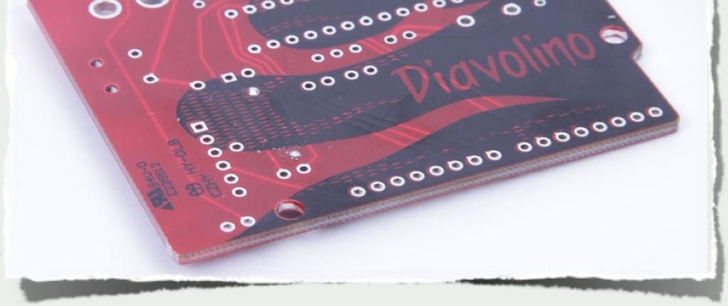
1 An open-source hardware+software project. For design files and additional documentation, please visit: Support: Distributed by Evil Mad Science LLC Kit version 1.0 Manual v. 1.0a
2 Bill of materials (for basic kit) Kit contents: Line Description Value Digi-Key Equiv. Qty 1 PCB Diavolino circuit board n/a 1 2 Quick-start card n/a 1 3 Resistor, 1/4W 1k 1.0QBK-ND 1 4 Resistor, 1/6W 10k 10KEBK-ND 1 5 Capacitors 18 pf BC1004CT-ND 2 (marked w/ black stripe in kits) 6 Capacitors 0.1 uf BC1148CT-ND 3 7 Tactile button switch Two pin CKN9102-ND 1 8 LED, 3 mm Red diffused P606-ND 1 9 Crystal 16 MHz ND 1 10 Header 6-position Right-angle SIL Microcontroller ATmega328P-PU ATMEGA328P-PU-ND 1 12 Wire Jumpers Zerohm, 1/4W form factor 0.0QTR-ND 3
 #1: Printed circuit board #9: Crystal #11: Microcontroller #5: 18 pf caps (2) #7: Button switch #10: Header #3: 1/4 W, 1 k")
3 #2: Quick start card Identifying the parts #6: 1 uf caps (3) (Black stripe!) #1: Printed circuit board #9: Crystal #11: Microcontroller #5: 18 pf caps (2) #7: Button switch #10: Header #3: 1/4 W, 1 k resistor #12: Wire jumpers (3) #8: LED #4: 1/6 W, 10 k resistor

 should get shiny when hot-- able to melt and wet to solder.")

 is the most common and best choice for this application.")

. And for Programming.")

4 Tool Checklist Essential tools: Needed to build the kit: 1. Soldering iron + solder A basic soldering iron meant for electronics, with a reasonably fine point tip. We recommend one of this design-- a "pencil shape" soldering iron (not gun!) with a base that holds the iron and a wet sponge. A tip in good condition (a tinned tip) should get shiny when hot-- able to melt and wet to solder. While you don t need an expensive one, the iron can make a big difference in the time needed to build the kit. (Seriously. If you use one that is old and busted, or a $10 radio shack iron, or that thing from the dollar store, please expect to spend at least twice as long soldering!) Our recommendation for a low-cost iron: model WLC100 by Weller, about $40. You ll also need some solder. Thin rosin-core solder (roughly in diameter) is the most common and best choice for this application. Either standard (lead-bearing) or newer lead free solder types will both work just fine. Optional but suggested: 1. Resistor lead forming tool Allows fast, neat bending of resistor leads. 2. Wire strippers If you re building your kit to run off of batteries, we recommend trimming the leads, for which you ll need to re-strip the ends. This model is our favorite: Ideal T-Stripper # (the gauge size). And for Programming... Diavolino is an Arduino compatible, but requires a programming interface. 2. Angle flush cutters For clipping loose wire ends close to the circuit board. e.g., Sears Craftsman 1. USB-TTL Cable FTDI model TTL-232R or equivalent. A smart converter cable with a USB interface chip inside. One end hooks up to your USB port, the other to Diavolino. This allows you to program Diavolino through the Arduino development environment ( Alternately, Diavolino can be programmed through an AVR ISP programmer, like the USBtinyISP. 2. Computer, Internet access, USB port... All of the software that you ll need is available online for free. You ll need a reasonably recent vintage computer (Mac, Windows, or Linux) and internet access to download that Arduino software.

 Also note that the wire jumpers (#12) are")

5 (AKA, the big one) (AKA, the little one) You need to be able to tell apart these two resistors. (The 1k resistor is the big one.) Also note that the wire jumpers (#12) are similar, but only have a single black stripe. #4: 1/6 W, 10 k resistor #3: 1/4 W, 1 k resistor #1: Printed circuit board

 Bend! (1). Insert each component into the circuit board, from the top, at its given location.")
.")
6 Some hints on soldering As the old Heathkit manuals say, it is interesting to note that the vast majority of problems reported with soldering kits turn out to be due to unreliable solder connections. Before we go further, here s a quick refresher, with our suggested procedures for adding components to the circuit board. These procedures apply to most components in the kit. Adding components to the circuit board (0). Pre-form the leads of components if needed. (For example, like these resistors). (1) Insert! (2) Bend! (1). Insert each component into the circuit board, from the top, at its given location. Push it flush to the board (Note that some components, like the chip and LED, need to be inserted with a particular orientation.) (2). If your component has flexible leads, gently bend the leads out, up to 45, to hold it in place while you solder. (3). One at a time, from the back side, solder the leads of the component to the circuit board. Your tip needs to be shiny (tinned). If not, melt some fresh solder against it and quickly swipe clean on a wet sponge. Place the solder against the joint that you wish to connect. Touch the iron to the solder and joint for about one second. Count it out: one thousand one. The solder should melt to the joint and leave a shiny wet-looking joint. If not, let it cool and try again. (4). If the component has long and/or or flexible leads, clip off the extra length, close to the board. (But not so close that you re clipping the board itself.) (3) Solder! (4) Clip! [6]


7 Let s start with the 1k resistor, #3. First, bend down the leads like so. Insert the resistor in the 1k location on the board. Push down until flush... Bend! And bend out the leads on the bottom.


8 Solder it. Visually inspect solder joints. Clip it. Correctly installed resistor.

9 Next: 10k resistor, #4. Install this resistor the same way, in the location marked 10 k.


10 18 pf caps, #5 The two 18 pf capacitors in the kits are marked by black stripes. If they are taped together, pull them straight out of the tape to use them. Add the two caps to the board here: Bend the leads out below the board, then solder and clip the leads.


11 0.1 uf caps, #6 There are three of these capacitors. Pull them out from the tape as before. Add the three caps in the locations shown. Bend out, solder, and trim the leads as usual.


12 Tactile button switch, #7 Insert the switch where shown. It may *snap* into place. You can bend the pins inward to hold this one in place while you solder. The leads are short and usually don t need trimming.


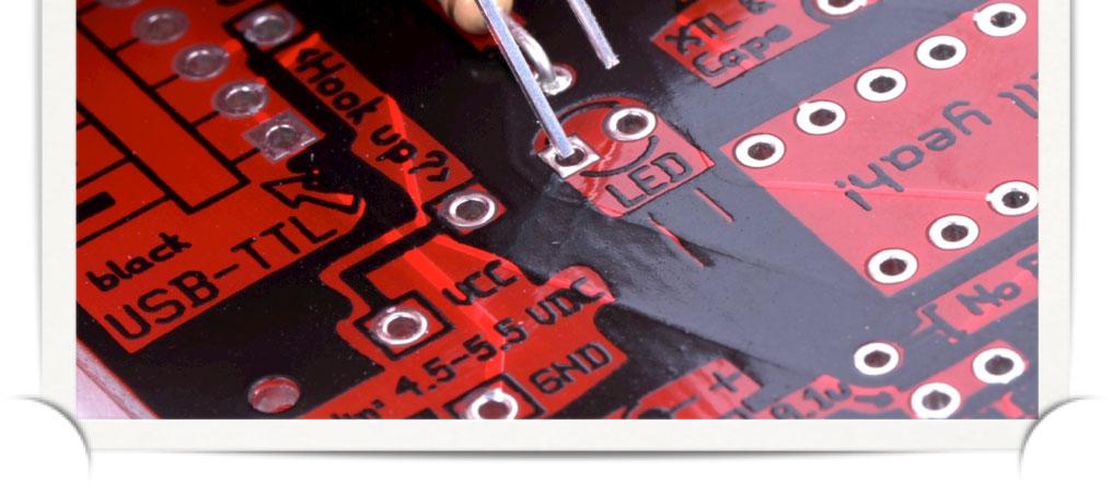

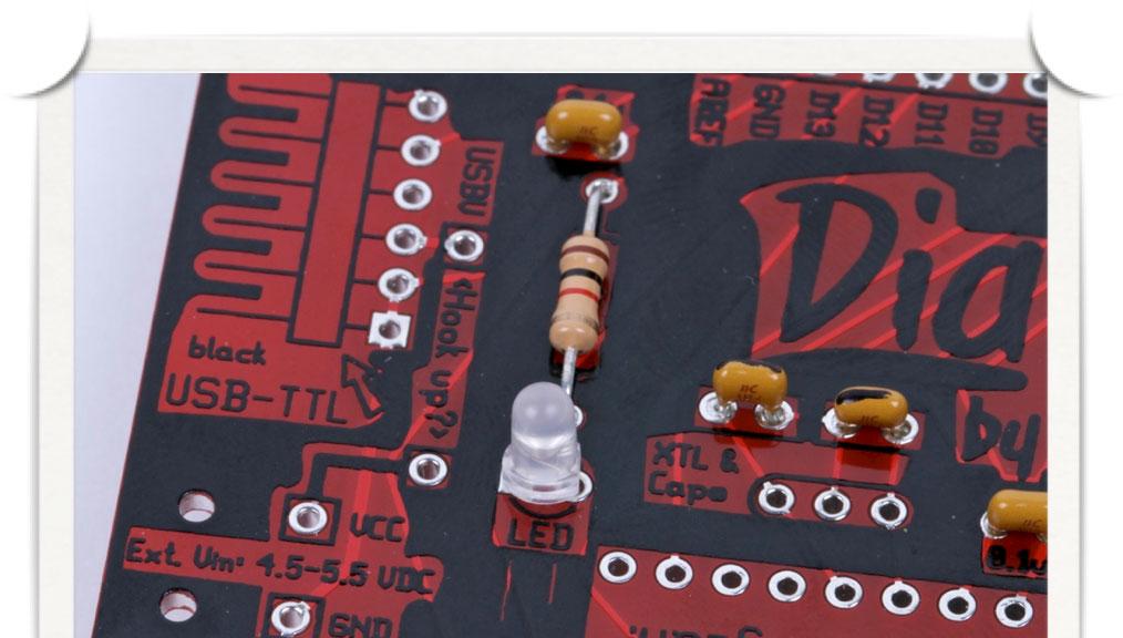
13 LED, #8 Put the long lead in the square hole. 3 mm red-diffused LED. Note the short and long leads: Orientation matters! Then push flush, solder & trim as usual.


14 16 MHz Quartz crystal oscillator, #9 Orientation does not matter, but the two pins go in the outer two holes of the three available. A shiny little can with two leads Then push flush, solder & trim as usual.


15 Header #10 This is the connector for the USB-TTL cable. Test-fit it in place so that you see where it goes. These pins don t bend. So, to hold it in place when you solder, first solder one of the pins from the top to tack it in place. Solder the other five pins from the back. You shouldn t need to trim them after soldering.


16 Time for the microcontroller. Orientation matters. You need to orient it with the half moon shape on one end of the chip matching that on the circuit board.


17 Carefully insert the chip. Again, double-check the orientation. The chip should easily slip into the board. If necessary, bend the pins of the chip to straight up and down before inserting the chip. Do not bend them by hand; bend all pins on one side at a time by pushing them against a hard flat surface. From end of chip: no. YES!


18 Flip the board over and solder the chip in place all 28 pins. Tip: Gently bend over the corner pins to hold the chip in place while you solder.


19 This concludes the essential portion of the build. Most users will also configure some of the option jumpers and/or add power sources. We ll get to these next.


 when operating at 16 MHz.")
20 * USBV jumper: Adding this wire jumper connects the USB 5V line to Vcc, providing power from USB to your circuit. Add this jumper if you want to power your Diavolino from a 5V USB-TTL cable. * Regulator jumper: This jumper connects the dc input ( Vin ) directly to Vcc. Use this jumper only if you are using a plug-in 5 V dc power supply, where no regulator is needed. If you are using a regulator, remove this jumper. * 3.3V jumper: The 3.3 V pin is normally unconnected. If you want to hook it to Vcc, you can add a wire jumper here. The AVR microcontroller requires V power (Vcc) when operating at 16 MHz. Be careful to only apply power from one source at a time: USB-TTL, dc adapter, or battery. For programming, you ll need an FTDI TTL-232R cable or an equivalent USB-TTL interface. Within the Arduino IDE, please select board type (from the menu) as Duemilanove w/ 328.

21 How to add a battery box The chip requires V DC when operating at 16 MHz. You can get 4.5 V from three Alkaline AA or AAA cells. 3xAA battery holder with switch Note 1: Rechargeable batteries will not normally provide a voltage in this range. Note 2: Be sure to use a battery box with a power switch, because you can only provide power from one source at a time.
 The Diavolino")


22 How to add a battery box (continued) The Diavolino fits nicely on a battery box like this. To make it even neater, you can trim the wire leads to a couple of inches (and strip the ends) to reduce the amount of excess wire. You can also mount it directly to the battery box with a strip of double-sided foam tape.


23 How to add a battery box (continued) Whether or not you trim the leads, here s the procedure: First, bring the wire leads up through the strain-relief holes at the edge of the board as shown. Then, solder the red wire in location VCC and the black wire in location GND. Pull any excess wire back through the strain-relief holes to take out the slack.
 The pins can t really be bent on the back side to hold them in place.")
24 Adding socket strips These socket strips are an optional extra for connecting to Arduino-style shield boards. Insert them where shown and solder them in place, flush to the board. two 6-pin & two 8-pin socket strips Notes: 1.) The pins can t really be bent on the back side to hold them in place. It s easier to tape them down with masking tape or just to turn the whole board over, resting on them. 2.) It s best to solder one pin on each first, to make sure that they re straight and flush, before soldering the rest. 3.) The pins are short enough that they don t normally need trimming.
 If you have a USB-TTL interface that provides 5 V, such as the FTDI TTL-232R-5V, you can")


25 Providing power from USB One of the zerohm jumpers. (It has one black stripe.) If you have a USB-TTL interface that provides 5 V, such as the FTDI TTL-232R-5V, you can hook that up to provide 5V power to your board. To make this connection, add a zerohm jumper to the USBV location on the circuit board. Note 1: Most computer USB interfaces are limited to sourcing 500 ma. Note 2: If you use this option, be sure to disconnect any other power sources when you plug in your USB- TTL cable, because you can only provide power from one source at a time.

26 Connecting USB-TTL cable The board is labeled with proper colors for connecting the FTDI USB-TTL cable. Green towards the top, black towards the bottom. (If you have a different type of USB-TTL interface, it may be helpful to know that the black end is the ground side.)
.")
 an external 5 V regulator with it. Jack Reg.")


27 Using a 5V DC power adapter This is a regulated 5 V DC power adapter (center positive). Since it directly gives you 5 V DC, you do not need (and cannot use) an external 5 V regulator with it. Jack Reg. bypass jumper ( No Reg ) To use this power adapter, just add the power jack and the regulator bypass zerohm jumper as shown. Note: If you use a power adapter, be sure to disconnect any other power sources when you plug in your adapter, because you can only provide power from one source at a time.


28 Using a > 6V DC power adapter This is a 9 V DC power adapter (center positive). Since it does not directly give you 5 V DC, you will need an 5 V regulator to use it. 5V regulator Besides the jack, you will also have to add the 5V regulator. DO NOT also use the regulator bypass jumper that would short-circuit the regulator.

,and a 10 uf")


29 Using a > 6V DC power adapter (continued) There are three parts to the regulator: A 0.1 uf ceramic capacitor (left), The regulator itself (middle),and a 10 uf electrolytic cap (right). Our normal regulator is type 750L05, a 150 ma regulator. You can also use a type L4931CZ50-AP 300 ma regulator. Orientation of the regulator matters: match the flat side to the drawing on the circuit board. Orientation of the 10 uf capacitor matters: Orient the side with the big - stripe towards the - on the circuit board. Note: Again, if you use a power adapter, be sure to disconnect any other power sources when you plug in your adapter, because you can only provide power from one source at a time.
30 Schematic Diagram (USBV Jumper) (Battery input) (Regulator jumper) (3.3 V Jumper) (black end) (green end)
RC Tractor Guy Controller V2.1 Assembly Guide
 RC Tractor Guy Controller V. Assembly Guide Features 0 Push button inputs Dual axis thumb sticks with built-in push button Rotary encoders with built-in push button MCU Socket to suit Meduino Mega 560
Post Tenebras Lab. Written By: Post Tenebras Lab
 Post Tenebras Lab PTL-ino is an Arduino comptaible board, made entirely out of through-hole components. It is a perfect project to learn how to solder and start getting into the world of micro controllers.
The GENIE Light Kit is ideal for introducing simple lighting projects, such as an electronic die, a wearable badge or a night-time warning system.
 Introduction 1 Welcome to the GENIE microcontroller system! The GENIE Light Kit is ideal for introducing simple lighting projects, such as an electronic die, a wearable badge or a night-time warning system.
RFX 328p dev/deployment board - Assembly instructions (long version, v1.3, Feb 12, 2015)
") RFX 328p dev/deployment board - Assembly instructions (long version, v1.3, Feb 12, 2015) Author: Mark Pendrith (support@embeddedcoolness.com) Kit overview The RFX 328/nRF24l01+/Proto dev board is a Arduino
RFX 328p dev/deployment board - Assembly instructions (long version, v1.3, Feb 12, 2015) Author: Mark Pendrith (support@embeddedcoolness.com) Kit overview The RFX 328/nRF24l01+/Proto dev board is a Arduino
Morse Code Practice Oscillator
 Features Description Keyer speed range: Limited only by keying source True Sine wave tone output Tone Volume Control Tone Frequency Control Internal Speaker 1/8 External Speaker/Headphone Jack RCA Key
Advanced Lantern 1.0 Kit. Introduction to the Advanced Lantern 1.0 Kit
 Advanced LED Lantern 1.0 Instruction Manual Eastern Voltage Research, LLC Introduction to the Advanced Lantern 1.0 Kit Thank you for purchasing the Advanced Lantern 1.0 Kit. This kit is an advanced microprocessor
OpenSprinkler v2.2u Build Instructions
 OpenSprinkler v2.2u Build Instructions (Note: all images below are 'clickable', in order for you to see the full-resolution details. ) Part 0: Parts Check Part 1: Soldering Part 2: Testing Part 3: Enclosure
Advanced Strobe 1.0 Kit
 Kit Instruction Manual Eastern Voltage Research, LLC December 2013, Rev 1 1 http://www.easternvoltageresearch.com Kit Introduction to the Kit Thank you for purchasing the Kit. If you are looking for a
Electronics Construction Manual
 Electronics Construction Manual MitchElectronics 2018 Version 1 07/05/2018 www.mitchelectronics.co.uk CONTENTS Introduction 3 How To Solder 4 Resistors 5 Capacitors 6 Diodes and LEDs 7 Switches 8 Transistors
OpenSprinkler v2.1u Build Instructions
 OpenSprinkler v2.1u Build Instructions (Note: all images below are 'clickable', in order for you to see the full-resolution details. ) Part 0: Parts Check Part 1: Soldering Part 2: Testing Part 3: Enclosure
Building and using JasperMIDI
 Building and using JasperMIDI Table of Contents Introduction... Bill Of Materials... 2 Building Choices... 3 Construction... 4 Installing in a Jasper enclosure... 5 Standalone use... 6 Using JasperMIDI...
Digital Flame 1.0 Kit
 Digital Flame 1.0 Kit Instruction Manual Eastern Voltage Research, LLC June 2012, Rev 1 1 http://www.easternvoltageresearch.com Introduction to the Digital Flame 1.0 Kit Thank you for purchasing the Digital
ARRL ETP Solder Hour Clock Kit Construction Manual
 ARRL ETP Solder 101 24-Hour Clock Kit Construction Manual Do a complete parts check cross checking the individual parts against the parts list. Pay particular attention to the color code for the resistors:
Building your own special-purpose embedded system gadget.
 Bare-duino Building your own special-purpose embedded system gadget. Saves a little money. You can configure the hardware exactly the way that you want. Plus, it s fun! bare-duino 1 Arduino Uno reset I/O
Arduino Uno. Arduino Uno R3 Front. Arduino Uno R2 Front
 Arduino Uno Arduino Uno R3 Front Arduino Uno R2 Front Arduino Uno SMD Arduino Uno R3 Back Arduino Uno Front Arduino Uno Back Overview The Arduino Uno is a microcontroller board based on the ATmega328 (datasheet).
K1EL Morse Code Practice Oscillator CPO
 Features This is an oscillator not a Morse keyer Input source can be a keyer or straight key Near Sine wave tone output CPO Tone Volume Control CPO Tone Frequency Control Use headphones or external speaker
ARDUINO MEGA 2560 REV3 Code: A000067
 ARDUINO MEGA 2560 REV3 Code: A000067 The MEGA 2560 is designed for more complex projects. With 54 digital I/O pins, 16 analog inputs and a larger space for your sketch it is the recommended board for 3D
K8099 NIXIE CLOCK. * optional enclosure TKOK19 (black) - TKOK17 (white) ** optional plexiglass enlcosure B8099 ILLUSTRATED ASSEMBLY MANUAL
 - TKOK17 (white) ** optional plexiglass enlcosure B8099 ILLUSTRATED ASSEMBLY MANUAL") Total solder points: 230 + 74 Difficulty level: beginner 1 2 3 4 5 advanced NIXIE CLOCK K8099 ** * A unique combination of both vintage and modern electronics ILLUSTRATED ASSEMBLY MANUAL H8099IP-1 * optional
Total solder points: 230 + 74 Difficulty level: beginner 1 2 3 4 5 advanced NIXIE CLOCK K8099 ** * A unique combination of both vintage and modern electronics ILLUSTRATED ASSEMBLY MANUAL H8099IP-1 * optional
Electronics Construction Manual
 Electronics Construction Manual MitchElectronics 2019 Version 3 04/02/2019 www.mitchelectronics.co.uk CONTENTS Introduction 3 How To Solder 4 Resistors 5 Capacitors 6 Diodes and LEDs 7 Switches 8 Transistors
Digital Candle 1.0 Kit
 Kit Instruction Manual Eastern Voltage Research, LLC June 2012, Rev 1 1 http://www.easternvoltageresearch.com Introduction to the Kit Thank you for purchasing the Kit. This kit is definitely a favorite
µrrc µr/c Robot Controller v1.1
 v1.1 OVERVIEW The µrrc is a simple, easy to use interface between a 3-channel R/C receiver and the OSMC H-Bridge controller for battle style robots. In principle, the µrrc can be used to drive any motor
LED Sequencer 1.0 / 1.5
 LED Sequencer 1.0 / 1.5 Instruction Manual Eastern Voltage Research, LLC May 2012, Rev 2 1 http://www.easternvoltageresearch.com Introduction to the LED Sequencer 1.0 Thank you for purchasing the LED Sequencer
Uzebox Kit Assembly Guide
 Uzebox Kit Assembly Guide V1.3 Page 1 of 18 Revision History Version Date Author Description 1.0 01-Nov-2012 A.Bourque Initial release 1.1 6-Nov-2012 A.Bourque Minor corrections 1.2 28-Jan-2014 A.Bourque
BUILDING YOUR KIT. For the Toadstool Mega328.
 BUILDING YOUR KIT For the Toadstool Mega328 www.crash-bang.com @crashbang_proto This work is licensed under a Creative Commons Attribution-ShareAlike 4.0 International License. Congratulations! You re
The Basic Counter. Hobby Electronics Soldering Kit. Instruction Guide
 The Basic Counter Hobby Electronics Soldering Kit Instruction Guide TM For the best outcome, follow each step in order. We recommend reading this guide entirely before you get started. Tools required:
Part 2: Building the Controller Board
 v3.01, June 2018 1 Part 2: Building the Controller Board Congratulations for making it this far! The controller board uses smaller components than the wing boards, which believe it or not, means that everything
Construction Construction Instructions
 Semi-Virtual Diskette SVD Construction Construction Instructions PCB version 2.0 September 2004 Eric J. Rothfus Table of Contents Table of Contents... i Parts List...1 Construction Overview...5 PCB Construction...
BS2p40tm OEM Module. Surface mount/through hole kit By Robert L. Doerr. Manual Revision.5
 BS2p40tm OEM Module Surface mount/through hole kit 2006 By Robert L. Doerr Manual Revision.5 NOTE: The BASIC Stamp and the BS2p40 and Interpreter chip are trademarks of Parallax. This partial kit allows
Universal Keying Adapter 3+
 Universal Keying Adapter 3+ The Universal Keying Adapter Version 3+ kit will allow you to key nearly any transmitter or transceiver with a straight key, electronic keyer, computer serial or parallel port
Building the Super-VMW CPU Meter by Vincent M. Weaver 18 May 2011
 Building the Super-VMW CPU Meter http://www.deater.net/weave/vmwprod/meter/super.html by Vincent M. Weaver 18 May 2011 1 Parts List Part No Description Quantity Source LED Board 1 SVMW-Meter-LED-Board
KDS Channel DMX Controlled Servo Kit
 KDS00801 8-Channel DMX Controlled Servo Kit This is a DMX512-A controlled servo kit using ANSI approved RJ-45 connectors for DMX networks. Power requirements are 8-20 VDC @ 50 ma. The board features an
UF-3701 Power Board Construction Guide
 Page 1/5 Soldering and Part Placement See the Chapter 3 of the MIT 6270 Manual for information on electronic assembly, including soldering techniques and component mounting. Construction Information All
Bill of Materials: 8x8 LED Matrix Driver Game PART NO
 8x8 LED Matrix Driver Game PART NO. 2171031 This Game Maker II kit is a game design platform using a single color 8x8 matrix LED without the need for a shift register or expensive Arduino. The kit includes
USB Controlled DMX interface
 USB Controlled DMX interface Control DMX fixtures using a PC and USB interface. Stand-alone test function that outputs all 512 channels at a time, with adjustable levels. Total solder points: 117 Difficulty
TinyTrak4 Kit Hardware Manual
 TinyTrak4 Kit Hardware Manual Version 0.7 July 23, 2017 Overview TinyTrak4 is a radio controller similar to a packet TNC, which can transmit and receive signals over a two-way radio. It can receive and
Pacific Antenna Easy TR Switch Kit
 Pacific Antenna Easy TR Switch Kit Kit Description The Easy TR Switch is an RF sensing circuit with a double pole double throw relay that can be used to automatically switch an antenna between a separate
ARDUINO UNO REV3 Code: A000066
 ARDUINO UNO REV3 Code: A000066 The UNO is the best board to get started with electronics and coding. If this is your first experience tinkering with the platform, the UNO is the most robust board you can
The Sudden Storm Kit. by QRPme. Builder s Guide. version4.2. for. Sudden Storm ][ Ver4 (red pcb) Updated 01/10/2012
![The Sudden Storm Kit. by QRPme. Builder s Guide. version4.2. for. Sudden Storm ][ Ver4 (red pcb) Updated 01/10/2012](/thumbs/75/72448638.jpg "The Sudden Storm Kit. by QRPme. Builder s Guide. version4.2. for. Sudden Storm ][ Ver4 (red pcb) Updated 01/10/2012") The Sudden Storm Kit by QRPme Builder s Guide version4.2 for Sudden Storm ][ Ver4 (red pcb) Updated 01/10/2012 Open the can and the adventure begins 1 Organize the parts and take an inventory Bill of Materials
The Sudden Storm Kit by QRPme Builder s Guide version4.2 for Sudden Storm ][ Ver4 (red pcb) Updated 01/10/2012 Open the can and the adventure begins 1 Organize the parts and take an inventory Bill of Materials
Installation/assembly manual for DCC/Power shield
 Installation/assembly manual for DCC/Power shield The DCC circuit consists of the following components: R1/R6 R2/R3 R4/R5 D1 C2 2 kω resistor ½ Watt (colour code Red/Black/Black/Brown/Brown) 10 kω resistor
EE 354 August 1, 2017 Assembly of the AT89C51CC03 board
 EE 354 August 1, 2017 Assembly of the AT89C51CC03 board The AT89C51CC03 board comes as a kit which you must put together. The kit has the following parts: No. ID Description 1 1.5" x 3.25" printed circuit
Building the FlipChip Tester
 Building the FlipChip Tester 1. Assembly of the Core Board You will need a fine low-wattage soldering iron and a Voltmeter. Take your time to solder the components on the Core Board. Better to spend a
ARDUINO UNO REV3 SMD Code: A The board everybody gets started with, based on the ATmega328 (SMD).
.") ARDUINO UNO REV3 SMD Code: A000073 The board everybody gets started with, based on the ATmega328 (SMD). The Arduino Uno SMD R3 is a microcontroller board based on the ATmega328. It has 14 digital input/output
ARDUINO UNO REV3 SMD Code: A000073 The board everybody gets started with, based on the ATmega328 (SMD). The Arduino Uno SMD R3 is a microcontroller board based on the ATmega328. It has 14 digital input/output
Interactive LED Modules
 Interactive LED Modules An open-source hardware+software project. For design files, source code, & additional documentation, please visit: http://wiki.evilmadscience.com/octolively Support: http://www.evilmadscientist.com/forum/
Building RoboPIC 18F4550
 RoboPIC 8F4550 Copyright 206 William Henning Building RoboPIC 8F4550 Copyright 206 William Henning RoboPIC 8F4550 build manual v0.90 The most up to date documentation will always be available at: http://www.mikronauts.com/robot-controllers/robopic-8f4550/
MP3 audio amplifier. Build Instructions. Issue 2.0
 MP3 audio amplifier Build Instructions Issue 2.0 Build Instructions Before you put any components in the board or pick up the soldering iron, just take a look at the Printed Circuit Board (PCB). The components
SRI-02 Speech Recognition Interface
 SRI-02 Speech Recognition Interface Data & Construction Booklet The Speech Recognition Interface SRI-02 allows one to use the SR-07 Speech Recognition Circuit to create speech controlled electrical devices.
ARDUINO MEGA ADK REV3 Code: A000069
 ARDUINO MEGA ADK REV3 Code: A000069 OVERVIEW The Arduino MEGA ADK is a microcontroller board based on the ATmega2560. It has a USB host interface to connect with Android based phones, based on the MAX3421e
Onwards and Upwards, Your near space guide. Figure 1. CheapBot Line Follower
 The CheapBot Line Follower is a plug-in single-board sensor for almost any programmable robot brain. With it, a robot can detect the presence of a black or white zone beneath its two sensors. In its simplest
Building the RGBW LED Controller
 Building the RGBW LED Controller A guide for the assembly and operation of your RGBW LED Controller. ver 3.1 Getting Started Parts list - You should have received the following parts: (1) Circuit Board,
Bill of Materials: Picaxe-based IR Control Module Pair PART NO
 Picaxe-based IR Control Module Pair PART NO. 2171014 The IRGEII is an IR (Infra Red) Transmitter and Receiver pair that uses a 38 KHZ frequency of invisible light to communicate simple instructions. The
AVR-M Rev 5 ASSEMBLY
 AVR-M Rev 5 ASSEMBLY The AVR_M is a very compact self contained Atmel AVR mcu controller board. It includes an onboard serial programmer (via PC com port), an I2C eeprom and can use a Mega163, Mega16 or
PARTS LIST 1 x PC Board 36 x 5mm Red LED 36 x 12mm LED Standoff 36 x NPN Transistor 36 x 10kΩ Resistor OTHER PARTS YOU MAY NEED
 PARTS LIST 1 x PC Board 36 x 5mm Red LED 36 x 12mm LED Standoff 36 x NPN Transistor 36 x 150Ω Resistor 36 x 10kΩ Resistor 17 x Mini Toggle on-off 8 x Mini Toggle (on)-off-(on) 1 x 470Ω Resistor 1 x 47µF
edrive RAM Battery Alternate Replacement Procedure
 edrive RAM Battery Summary This technical note describes the process for replacing the TINI RAM battery with a higher capacity battery. With the edrive turned on, the external battery can be changed without
BuffaloLabs WiFi Lantern Assembly guide version 1
 BuffaloLabs WiFi Lantern Assembly guide version 1 Needed equipment: Solder iron Solder wire Cutter Wire stripper (optional) Hot glue gun Overview of the components (not including USB cable and box panels)
Wind Logger Shield. Parts included: Date: 29/07/14 Version: 1.0 By: Matt Little
 Wind Logger Shield Date: 29/07/14 Version: 1.0 By: Matt Little Parts included: This is a simple shield to easily implement a wind resource data logging system. It is designed to read 2 x pulse type anemometers
IQ32 Upgrade Kit Assembly Instructions
 IQ32 Upgrade Kit Assembly Instructions Jim Veatch WA2EUJ September 17, 2018 TABLE OF CONTENTS 1. INTRODUCTION... 3 2. IQ-32 UPGRADE KIT INVENTORY... 4 3. PREPARING THE RS-HFIQ AND SIDE PANELS... 6 4. CONNECTING
QUASAR KIT No DIGITAL DOWN TIMER 99 MIN WITH PIC
 QUASAR KIT No 1173 - DIGITAL DOWN TIMER 99 MIN WITH PIC KIT 1173 is a digital countdown timer based on a micro controller, thus securing reliability and excellent operation under any circumstances. It
QUASAR ELECTRONICS KIT No Hi-Fi PREAMPLIFIER WITH REMOTE CONTROL
 QUASAR ELECTRONICS KIT No. 1070 Hi-Fi PREAMPLIFIER WITH REMOTE CONTROL General Description This is a hi-fi STEREO preamplifier based on a single integrated circuit which employs a revolutionary new method
Shack Clock kit. U3S Rev 2 PCB 1. Introduction
 Shack Clock kit U3S Rev 2 PCB 1. Introduction Thank you for purchasing the QRP Labs Shack Clock kit. This clock uses the Ultimate3S QRSS/WSPR kit hardware, but a different firmware version. It can be used
W0EB/W2CTX DSP Audio Filter Construction Manual V3.02.1
 W0EB/W2CTX DSP Audio Filter Construction Manual V3.02.1 Manual and photographscopyright W0EB/W2CTX, January 01, 2019. This document may be freely copied and distributed so long as no changes are made and
Assembling the Printed Circuit Board for the EDE1200 Robot
 This board receives instructions from either a CBL2, a LabPro or (with an adapter cable) an original CBL. The board has two 595 shift registers (each providing 8 bits of on-board memory) and two EDE1200
Bill of Materials: Handheld Game System PART NO
 Handheld Game System PART NO. 2245108 Build your own Handheld Game System with graphics and sound! This game kit includes a custom designed circuit board along with custom built tools and programming to
Celadon, Inc. TRX Series Infrared Remote and Receiver Assembly and Operation Instruction Manual
 Celadon, Inc. TRX Series Infrared Remote and Receiver Assembly and Operation Instruction Manual REV 2.1 COPYRIGHT 2001 I. Introduction Thank you for purchasing your infrared remote control transmitter
3 pyro output datalogger altimeter with an ATmega 328 microcontroller Kit assembly instructions
 3 pyro output datalogger altimeter with an ATmega 328 microcontroller Kit assembly instructions Version date Author Comments 1.0 29/05/2013 Boris du Reau Initial version Rocket Type Micro-max Model Mid
Uzebox Kit Assembly Guide
 Uzebox Kit Assembly Guide V1.7 Page 1 of 21 Revision History Version Date Author Description 1.0 01-Nov-2012 A.Bourque Initial release 1.1 6-Nov-2012 A.Bourque Minor corrections 1.2 28-Jan-2014 A.Bourque
Adafruit USB Power Gauge Mini-Kit
 Adafruit USB Power Gauge Mini-Kit Created by Bill Earl Last updated on 2017-07-14 11:55:04 PM UTC Guide Contents Guide Contents Overview Assembly Basic Assembly Solder the female connector. Solder the
Tone Bender Mk III. Grandaddy of super-cool vintage fuzz tone
 Tone Bender Mk III Grandaddy of super-cool vintage fuzz tone Contents of this document are 2014 Pedal Parts Ltd. No reproduction permitted without the express written permission of Pedal Parts Ltd. All
Lab 0: Wire Wrapping Project: Counter Board
 Lab 0: Wire Wrapping Project: Counter Board September 3, 2008 In this experiment, you will build a simple counter circuit that can be plugged into your breadboard. It will provide a set of TTL output signals
Pacific Antenna Two Tone Generator
 Pacific Antenna Two Tone Generator Description Our Two Tone Generator kit provides two non-harmonic, sine wave signals for testing audio circuits Outputs of approximately 700Hz and 1900Hz and the combination
Rapid28iXL PIC Prototyping PCB User Manual
 Description Features This is a PCB designed to facilitate the rapid prototyping of a device based on a 28 pin Microchip PIC microcontroller. To allow users to focus on their application, we take care of
Arduino ADK Rev.3 Board A000069
 Arduino ADK Rev.3 Board A000069 Overview The Arduino ADK is a microcontroller board based on the ATmega2560 (datasheet). It has a USB host interface to connect with Android based phones, based on the MAX3421e
Figure 1. The Programmable Flight Computer.
 The BalloonSat Flight Computer There are 22 parts in this BalloonSat flight computer, the heart of which is the PICAXE- 08M2. The PICAXE is a microcontroller; making the BalloonSat Flight Computer programmable.
Rapid40i PIC Prototyping PCB User Manual
 Description This is a PCB designed to facilitate the rapid prototyping of a device based on a 40 pin Microchip PIC microcontroller. To allow users to focus on their application, we take care of key housekeeping
ARDUINO LEONARDO WITH HEADERS Code: A000057
 ARDUINO LEONARDO WITH HEADERS Code: A000057 Similar to an Arduino UNO, can be recognized by computer as a mouse or keyboard. The Arduino Leonardo is a microcontroller board based on the ATmega32u4 (datasheet).
1/Build a Mintronics: MintDuino
 1/Build a Mintronics: The is perfect for anyone interested in learning (or teaching) the fundamentals of how micro controllers work. It will have you building your own micro controller from scratch on
Rapid40iXL PIC Prototyping PCB User Manual
 Description This is a PCB designed to facilitate the rapid prototyping of a device based on a 40 pin Microchip PIC microcontroller. To allow users to focus on their application, we take care of key housekeeping
High Power (15W + 15W) Stereo Amplifier
 Stereo Amplifier") High Power (15W + 15W) Stereo Amplifier Build Instructions Issue 1.0 Build Instructions Before you put any components in the board or pick up the soldering iron, just take a look at the Printed Circuit
High Power (15W + 15W) Stereo Amplifier Build Instructions Issue 1.0 Build Instructions Before you put any components in the board or pick up the soldering iron, just take a look at the Printed Circuit
8 CHANNEL USB RELAY CARD
 8 CHANNEL USB RELAY CARD Use your computer USB port to connect to the outside world. Total solder points: 363 Difficulty level: beginner 1 2 3 4 5 advanced K8090 ILLUSTRATED ASSEMBLY MANUAL H8090IP-1 Features
Total solder points: 240 Difficulty level: beginner advanced LIGHT COMPUTER K5201 ILLUSTRATED ASSEMBLY MANUAL
 Total solder points: 240 Difficulty level: beginner 1 2 3 4 5 advanced LIGHT COMPUTER K5201 16 different patterns and 7 outputs provide a unique light show. ILLUSTRATED ASSEMBLY MANUAL H5201IP-1 Features
DELUXE STEREO AMPLIFIER KIT
 ESSENTIAL INFORMATION BUILD INSTRUCTIONS CHECKING YOUR PCB & FAULT-FINDING MECHANICAL DETAILS HOW THE KIT WORKS CREATE YOUR OWN SPEAKER DOCK WITH THIS DELUXE STEREO AMPLIFIER KIT Version 2.0 Build Instructions
TIME WIZARD MULTI CLOCK DIVIDER BUILDING GUIDE
 TIME WIZARD MULTI CLOCK DIVIDER BUILDING GUIDE Table of Contents 0. Components List + Tools 0. PCB Sides 03. PCB Assembly 04_. Diode N448 04_. Laying Resistors 04_3. Capacitors 04_4. Quartz 04_5. 78L05
*on-board power supply capability limited. External battery should be used for higher power servos.
 Pan and Tilt Decoder II PART NO. Add affordable Pan and Tilt control to your security cameras using the Pan and Tilt Decoder II and the DFRobot DF05BB Tilt/Pan Kit (5kg), Jameco PN 2144518 or the DAGU
SM010, Assembly Manual PCB Version 1.0
 180 SM010, Assembly Manual MATRIXARCHATE 16 8 IO SEQUENTIAL MATRIX SIGNAL ROUTER SM010 1 2 1 2 3 4 5 3 4 5 6 7 8 9 10 11 12 6 7 8 9 10 11 12 13 14 15 16 PROGRAM A B C D E F G H f1 f2 20.000 180 SSSR Labs
RECORD & PLAYBACK KIT
 ESSENTIAL INFORMATION BUILD INSTRUCTIONS CHECKING YOUR PCB & FAULT-FINDING MECHANICAL DETAILS HOW THE KIT WORKS ADD AN AUDIO MESSAGE TO YOUR PRODUCT WITH THIS RECORD & PLAYBACK KIT Version 2.1 Build Instructions
Alesis MMT8 16x Memory Expansion Modification (Black model MMT8 s) Equipment. Components required. Other bits:
 Equipment. Components required. Other bits:") Alesis MMT8 16x Memory Expansion Modification (Black model MMT8 s) by Graham Meredith, 006 Revised 15 th January 009 gmeredith1@yahoo.com.au This modification expands the memory of the Alesis MMT8 to 16x
Alesis MMT8 16x Memory Expansion Modification (Black model MMT8 s) by Graham Meredith, 006 Revised 15 th January 009 gmeredith1@yahoo.com.au This modification expands the memory of the Alesis MMT8 to 16x
LED Knight Rider. Yanbu College of Applied Technology. Project Description
 LED Knight Rider Yanbu College of Applied Technology Project Description This simple circuit functions as a 12 LED chaser. A single illuminated LED 'walks' left and right in a repeating sequence, similar
Shack Clock kit PCB Revision: QCU Rev 1 or QCU Rev 3
 1. Introduction Shack Clock kit PCB Revision: QCU Rev 1 or QCU Rev 3 Thank you for purchasing this QRP Labs Shack Clock kit. The kit uses the same PCB and bag of components as some other QRP Labs kits.
Populating and Installing Synthex Rev 2/3 EPROM adapter board. R Grieb 5/13/2018
 Populating and Installing Synthex Rev 2/3 EPROM adapter board. R Grieb 5/13/2018 Please read these instructions before purchasing or installing the EPROM adapter, to make sure you are comfortable performing
RC-210 Repeater Controller Assembly Manual
 Arcom Communications 24035 NE Butteville Rd Aurora, Oregon 97002 (503) 678-6182 arcom@ah6le.net RC-210 Repeater Controller Assembly Manual Hardware Version 3.0 Original Release Date September 13, 2004
TKEY-1. CW touch key. (no electromechanical contacts) Assembly manual. Last update: June 20,
 Assembly manual. Last update: June 20,") TKEY-1 CW touch key (no electromechanical contacts) Assembly manual Last update: June 20, 2017 ea3gcy@gmail.com Updates and news at: www.ea3gcy.com Thanks for constructing the TKEY-1A CW touch key Have
TKEY-1 CW touch key (no electromechanical contacts) Assembly manual Last update: June 20, 2017 ea3gcy@gmail.com Updates and news at: www.ea3gcy.com Thanks for constructing the TKEY-1A CW touch key Have
Construction Manual for the W0EB/N5IB New ubitx Raduino Clone
 Construction Manual for the W0EB/N5IB New ubitx Raduino Clone Version 1.5, January 09, 2019 Manual and Images Copyright W0EB and N5IB August 03. 2018, all rights reserved. May be freely reproduced and
Figure 1. The BalloonSat Mini v4.0 Programmable Flight Computer. Parts List
 The heart of the NearSys Mini v4.0 flight computer is the PICAXE-08M2. The PICAXE is a microcontroller and that makes the BalloonSat Flight Computer programmable. The PICAXE-08M2 s internal memory is limited
DMX CONTROLLED RELAY K8072
 Total solder points: 167 Difficulty level: beginner 1 2 3 4 5 advanced DMX CONTROLLED RELAY K8072 f the means o ol. y b y la a re 2 protoc Control DMX51 wn well-kno ILLUSTRATED ASSEMBLY MANUAL Total solder
8051 Intermidiate Development Board. Product Manual. Contents. 1) Overview 2) Features 3) Using the board 4) Troubleshooting and getting help
 Overview 2) Features 3) Using the board 4) Troubleshooting and getting help") 8051 Intermidiate Development Board Product Manual Contents 1) Overview 2) Features 3) Using the board 4) Troubleshooting and getting help 1. Overview 2. Features The board is built on a high quality FR-4(1.6
8051 Intermidiate Development Board Product Manual Contents 1) Overview 2) Features 3) Using the board 4) Troubleshooting and getting help 1. Overview 2. Features The board is built on a high quality FR-4(1.6
Breadboard Voltage. Convenient 5V Supply for Breadboard
 Breadboard Voltage Regulator v2.1 Convenient 5V Supply for Breadboard Turn your 6~18VDC Wall Wart adapter into a regulated 5VDC @ 0.5 Ampere supply for your breadboard experiments! Build Time: 20mins Skill
Effects Loop Installation Guide
 Warnings and Disclaimer Effects Loop Installation Guide You will be working with HIGH VOLTAGE. These voltages CAN BE DEADLY if you are not extremely careful. If you are not comfortable working with HIGH
PICAXE EXPERIMENTER BOARD (AXE090)
") (AXE00) Description: The PICAXE experimenter board allows circuits for any size/revision of PICAXE chip ( / / ) to be quickly tested using a prototyping breadboard. The experimenter board provides power
(AXE00) Description: The PICAXE experimenter board allows circuits for any size/revision of PICAXE chip ( / / ) to be quickly tested using a prototyping breadboard. The experimenter board provides power
TuBbika SMR-4-PLUS voicecard
 TuBbika SMR-4-PLUS voicecard Assembly instructions We assume you know soldering. If you don t, look first at this tutorial. Be patient! And if you have any doubt, head to the forum never be afraid to ask!
ATTiny84/85 AVR adapter kit building and usage instructions
 ATTiny84/85 AVR adapter kit building and usage instructions Version date Author Comments 1.0 25/06/2013 Boris du Reau Initial version 1.1 30/09/2013 Boris du Reau Updated document 1 Goal... 2 2 Kit content...
ARDUINO LEONARDO ETH Code: A000022
 ARDUINO LEONARDO ETH Code: A000022 All the fun of a Leonardo, plus an Ethernet port to extend your project to the IoT world. You can control sensors and actuators via the internet as a client or server.