Go to: 01/001. Contents EASY Control Relay. Page System overview 01/002
|
|
|
- Arline Banks
- 6 years ago
- Views:
Transcription
1 DEL ALT Contents 01/001 ESC OK Page System overview 01/002 Description EASY800 networking 01/006 EASY control relay Basic units 01/007 Expansion units 01/009 Accessories 01/010 Technical data 01/012 Dimensions 01/029
2 01/002 System overview POW BUS POWER ESC COM-ERR ADR DEL ALT 8 ESC OK 9 RUN ERR MS NS
3 System overview 01/003 Basic units 1 AC or DC operated Power supply AC 100 (115) 240 V, 50/60 Hz DC 24 V DC DA 12 V DC 8 digital inputs (2 inputs available as analog inputs [DC/DA variants only]) 4 relay outputs (max. 10 A) 4 transistor outputs LCD display, X variants without LCD Screw fixing and snap fitting Screw terminals a Page 01/007 Expansion unit 2 I/O expansion AC or DC operated Power supply AC V, 50/60 Hz DC 24 V DC 12 digital inputs 6 relay outputs (max. 10 A) 8 transistor outputs Screw fixing and snap fitting Screw terminals a Page 01/009 Expansion unit 3 EASY202-RE Output expansion 2 relay outputs (max. 10 A) Screw fixing and snap fitting Screw terminals a Page 01/00 9 Coupling unit 4 a Page 01/009 Connection cable 5 e.g. NYM 3 x 1.5 mm 2 Networking interfaces 6 EASY204-DP (in preparation for EASY800) PROFIBUS-DP slave connection EASY205-ASI AS-Interface slave connection EASY221-CO CANopen interface EASY222-DN DeviceNet interface a Page 01/009 Basic units, expandable EASY AC or DC operated Power supply AC V, 50/60 Hz DC 24 V DC 12 digital inputs (4 inputs available as analog inputs [DC variants only]) 6 relay outputs (max. 10 A) 8 transistor outputs 1 analog output 0 10 V (10 bit) LCD display, X variants without LCD Screw fixing and snap fitting Screw terminals NET network integrated a Page 01/007 EASY-LINK-DS data plug 11 For connecting the basic unit with the expansion unit a Page 01/010 Basic units, expandable EASY619/621 AC or DC operated Power supply AC V, 50/60 Hz DC 24 V DC 12 digital inputs (2 inputs available as analog inputs [DC variants only]) 6 relay outputs (max. 10 A) 8 transistor outputs LCD display, X variants without LCD Screw fixing and snap fitting Screw terminals a Page 01/007 Features of the EASY control relay Wide operational temperature range -25 C to +55 C Standard front dimension for fitting into service distribution boards, 18 mm standard space unit Electronic wiring at the touch of a button, LCD and keypad or software (PC) Retentive internal and external storing of circuit diagram in EEPROM memory 3 contacts (EASY400, EASY600), 4 contacts (EASY800) (make or break) in series plus one coil per circuit connection Series and parallel connection 41 circuit connections EASY circuit connections EASY circuit connections EASY600 Integral password protection for circuit diagram and relay value presets Current flow display for circuit diagram testing (LCD types) Ten menu languages (EASY600, EASY800) and five menu languages (EASY412) D, GB, F, I, E, (P, NL, S, PL, TR) With LCD types, the circuit diagram can be stored on memory card 12 Functions 8 timing relays 0.01 s to 99 h 59 min On-delay On-delay with random switching Off-delay Off-delay with random switching Single-pulse Flashing 32 timing relays (EASY800) On-delay On-delay with random switching Off-delay Off-delay with random switching On-delayed and off-delayed, random switching Single-pulse Flashing 8 up and down counter relays, 0000 to counter relays (EASY800) Value range g frequency counters (EASY800) Max. counter frequency ~5kHz 4 high-speed counters (EASY800) Max. counter frequency ~5kHz 2 incremental counters (EASY800) Max. counter frequency ~3kHz 4 operating hours counters (EASY800), retentive 4 7-day time switches (4 channels per time switch, one On/Off point per channel, optional on types with clock) 32 7-day time switches (EASY800) (4 channels per time switch, one On/Off point per channel) 32 year time switches (EASY800) (4 channels per time switch, one On/Off point per channel) 8 analog value comparators range 0 10 V (only EASY4..-D...-,EASY6..-D types) 32 analog value comparators range 0 10 V (only EASY8...-D... types) 8 freely editable text displays (EASY600 with LCD), using EASY-SOFT 32 freely editable text displays (EASY800 with LCD), using EASY-SOFT 16 auxiliary relays (EASY412), up to 32 auxiliary relays (EASY600) 96 markers (EASY800) 32 arithmetic function blocks (EASY800) ADD; SUB; MUL; DIV 32 Boolean sequences (EASY800) AND; NOT; OR Retentive actual values EASY412-D... 4 markers, 1 timing relay, 1 counter Retentive actual values EASY markers, 2 timing relays, 4 counters (e.g. for operating hours counters) Retentive actual values EASY bytes possible, data = MB (marker bytes) function blocks = C; CF; CH; CI; DB; T i.e. 80 MB and up to 40 function blocks depending on memory required 4 operating hours counter 0 to 10 hours (resolution: minutes)

4 01/004 System overview Start up and control SIMPLY easy The new control relay, easy800, combines virtually all the performance features of a PLC with the handling convenience of easy. Together, with the easy400 and easy600, it forms a cohesive system with uniform accessories, software and operation, designed for intelligent solutions in machine and instrument control or in building services. Rapid commissioning Great space savings easy One for all The indication of where current is flowing in the circuit, during actual operation or testing, simplifies and speeds up commissioning and makes it more reliable. All the easy devices have a current flow indicator. There is space for easy anywhere. The standard 1.8 (45mm) front dimension is equally suitable for use in service distribution boards in building services installations, or in control panels on machines and in industrial control systems. In each case, the easy replaces several conventional components and switching devices in a fraction of their space requirement. The easy series of programmable control relays offers the user three variations of each model, suitable for a wide range of applications. There are the AC devices with isolated relay outputs, and DC devices with the option of relay or transistor outputs. The voltage range for the input signals is always the same as the supply voltage. The easy relays are fully functionalin temperature ranges from -25 to +55 C.


5 System overview 01/005 Logic links instead of wiring Circuit diagrams form the basis for all electrical applications. Normally, these circuits are then implemented by the wiring of switching and control devices. With the easy programmable control relay, these connections are made simply by using the keypad on the front of the easy or by the use of the convenient easy-soft software. The procedure is simple and menu-guided in either 5 or 10 languages. This saves mounting and wiring costs and above all, precious time, making the easy applicable in all markets. The easy400 control relay Eight inputs, four relay or transistor outputs. In all the DC versions, there is the option of two analog inputs. The easy412 has three contacts and one coil for circuit configuration in each of up to 41 lines of logic. The easy600 control relay Twelve inputs, six relay or eight transistor outputs. In all the DC versions, there is the option of two analog inputs. The easy600 has three contacts and one coil in series for circuit configuration in each of up to 121 lines of logic. The built-in display can show up to eight texts of 48 characters each. For each text, two variables or module parameters can be included in the display. The user can thus read texts and values on the display in plain text. The easy800 control relay Twelve inputs, six relay or eight transistor outputs. In all the DC versions, there is the option of four analog inputs and also of one analog output. The easy800 has four contacts and one coil in series for circuit configuration in each of up to 256 lines of logic. The built-in display can show up to 32 texts of 64 characters each. For each text, the user can include several variables or module parameters in the display at any point. He can thus read texts and values on the display in plain text. Counting high-speed signals, measuring frequency or evaluating incremental encoder readings are no problem with easy800. Computing, data storage or communication via the NET network - all simply easy.
6 01/006 Description EASY800 Control Relay Location 1 Station 1 Location 2 Station 4 Location 3 Station 8 Location 8 Station 5 ESC DEL ALT OK DEL ESC ALT OK DEL ESC ALT OK ESC DEL ALT OK AS-Interface Networking Addressing of stations: Once all stations are connected, the addresses can be assigned automatically with the station number the same as the geographical location. The stations can also be addressed individually. The geographical address does not have to be the same as the station address. Example of a network topology: Four stations are connected up. Station address 1 is always the first location. All other station addresses do not correspond to the geographical location. Technical data Up to 320 digital inputs and outputs are possible 8 stations Baud rate: 10 Kbit/s to 1000 Kbit/s Length: up to 1000 m possible Operating modes. 1 master (location 1, station address 1), 7 I/O stations up to 1 master (location 1, station address 1) and 7 I/O intelligent stations Transfer up to 32 double words Synchronise time, date Direct access to input and output Program download and upload via NET
7 Basic units 01/007 Description Typ Article no. Price See Price List Basic units 24 V DC, retentive 8 digital inputs (2 inputs available as analog inputs) 4 relay outputs LCD display Operating buttons Screw terminals Features same as EASY-412-DC-R, additional time switch EASY412-DC-R EASY412-DC-RC DEL ALT ESC OK Features same as EASY412-DC-RC, without keypad and LCD display EASY412-DC-RCX digital inputs (2 inputs available as analog inputs) 4 transistor outputs LCD display Operating buttons Screw terminals Time switch EASY412-DC-TC Features same as EASY412-DC-TC, without keypad and LCD display EASY412-DC-TCX digital inputs (2 inputs available as analog inputs) 6 relay outputs LCD display Operating buttons Screw terminals Time switch Can be expanded using EASY expansion units EASY619-DC-RC Features same as EASY619-DC-RC, without keypad and LCD display EASY619-DC-RCX digital inputs (2 inputs available as analog inputs) 8 transistor outputs LCD display Operating buttons Screw terminals Time switch Can be expanded using EASY expansion units EASY621-DC-TC Features same as EASY621-DC-TC, without keypad and LCD display EASY621-DC-TCX digital inputs (4 inputs available as analog inputs) 6 relay outputs LCD display Operating buttons Screw terminals Time and date switch Can be expanded using EASY expansion units EASY819-DC-RC Features same as EASY819-DC-RC, without keypad and LCD display EASY819-DC-RCX digital inputs (4 inputs available as analog inputs) 6 relay outputs 1 analog output LCD display Operating buttons Screw terminals Time and date switch Can be expanded using EASY expansion units EASY820-DC-RC Features same as EASY820-DC-RC, without keypad and LCD display EASY820-DC-RCX
8 01/008 Basic units Description Typ Article no. Price See Price List Basic units 24 V DC, retentive 12 digital inputs (4 inputs available as analog inputs) 8 transistor outputs LCD display Operating buttons Screw terminals Time and date switch Can be expanded using EASY expansion units EASY821-DC-TC DEL ALT ESC OK Features same as EASY821-DC-TC, without keypad and LCD display 12 digital inputs (4 inputs available as analog inputs) 8 transistor outputs 1 analog output LCD display Operating buttons Screw terminals Time and date switch Can be expanded using EASY expansion units EASY821-DC-TCX EASY822-DC-TC Features same as EASY822-DC-TC, without keypad and LCD display EASY822-DC-TCX V DC, retentive 8 digital inputs (2 inputs available as analog inputs) 4 relay outputs LCD display Operating buttons Screw terminals Time switch EASY412-DA-RC /230 V AC 8 digital inputs 4 relay outputs LCD display Operating buttons Screw terminals EASY412-AC-R Features same as EASY-412-AC-R, additional time switch EASY412-AC-RC Features same as EASY412-AC-RC, without keypad and LCD display EASY412-AC-RCX /230 V AC, retentive 12 digital inputs 6 relay outputs LCD display Operating buttons Screw terminals Time switch Can be expanded using EASY expansion units Replaces EASY618-AC-RC EASY619-AC-RC Features same as EASY619-AC-RC, without keypad and LCD display EASY619-AC-RCX digital inputs 6 relay outputs LCD display Operating buttons Screw terminals Time and date switch Can be expanded using EASY expansion units EASY819-AC-RC Features same as EASY819-AC-RC, without keypad and LCD display EASY819-AC-RCX
9 Expansion units 01/009 Description Typ Article no. Price See Price List Expansion units 24V DC 115/230 V AC 12 digital inputs 8 transistor outputs 12 digital inputs 6 relay outputs 12 digital inputs 6 relay outputs EASY620-DC-TE EASY618-DC-RE EASY618-AC-RE Without power supply 2 relay outputs (common potential) EASY202-RE Coupling unit Coupling unit for connecting to an EASY619/621 basic unit Terminals for remote expansion, up to 30 m to the expansion unit EASY200-EASY Expansion units for networking AS-Interface PROFIBUS-DP CANopen DeviceNet AS-Interface connection Slave 4 inputs, 4 outputs, 4 parameter bits Addresses available: 0 to 31 PROFIBUS-DP slave Addresses available: 1 to 126 CANopen interface Addresses available: 1 to 127 DeviceNet interface Addresses available: 0 to 63 EASY205-ASI EASY204-DP EASY221-CO EASY222-DN DP accessories PROFIBUS-DP bus connector plug 9-pole (male), Kit without cable for connecting the data cable Metallised insulated housing Maximum SP transfer rate 12 MBit/s Integrated switch (accessible from the outside) for the bus terminating resistors Terminal block for two cable inputs, optionally with straight or 90 angled cable entry Suitable for EASY204-DP PROFIBUS-DP data cable 2-wire 2 x 0.64 mm 2 twisted Length 100 m ZB4-209-DS ZB4-209-DS ZB4-900-KB
10 01/010 Networking, Accessories Description Typ Article no. Price See Price List Accessories Software Memory card CD, menu selection in 6 languages Installation WIN 98, WIN NT 4.0 (SP6), WIN ME, WIN2000 (SP2), WIN XP 8K memory card for storing the entire EASY circuit diagram for EASY K memory card for storing the entire EASY circuit diagram for EASY6... EASY-SOFT EASY-M-8K EASY-M-16K K memory module for storing the entire EASY circuit diagram for EASY8... EASY-M-256K Connection cable 2 m length, for connection to 9-pole serial PC interface with interface electronics for EASY and EASY6... EASY-PC-CAB m length, for connection to 9-pole serial PC interface with interface electronics for EASY8... EASY800-PC-CAB Input/output simulator Simulator with power supply unit, 120 V AC / 24 V DC output, plug suitable for North America EASY412-DC-SIM-NA Fixing bracket For screw fixing on mounting plate For screw fixing on mounting plate 3 brackets per EASY brackets per EASY brackets per EASY brackets per EASY2... Coupling piece Spare link between basic unit and expansion units Telescopic adapter With 35 mm top-hat rail to EN for equalization of the mounting depth of rear mounted devices in CI-K... enclosures and cabinets. Adjustable as required via scales of mm. Screw and snap fastener (also suitable for PKZM0, FAZ, FIP, ETR, EMR4, etc.) Switched-mode power supply unit Primary-switched mode, stabilized Rated input voltage: 50/60 Hz: 115/230 V Rated output voltage: 24 V/12 V Rated output current: 0.25 A/20 ma Rated input voltage: 50/60 HZ: 115/230 V AC Rated output voltage (residual ripple): 24 V DC (g 3 %) Rated output current: 1.25 A Upstream device To increase the AC input current 6 channels ZB4-101-GF EASY-LINK-DS M22-TA EASY200-POW EASY400-POW EASY256-HCI
11 Networking, Accessories, Documentation 01/011 Description Typ Article no. Price See Price List Accessories Network connection cable (remote coupling) Completely prepared for EASY8... NET Length: 0.3 m Data cable Remote coupling Length: 0.8 m Length: 1.5 m 4-wire 4 x 0.18 mm 2, twisted pair, AWG 26 Length 100 m Bus connector for NET network 8-pole, RJ45 Bus terminating resistor, complete with connector for NET Crimping tool For 8-pin RJ45 connector EASY-NT EASY-NT EASY-NT EASY-NT-CAB EASY-NT-RJ EASY-NT-R EASY-RJ45-TOOL (SKF) inspection flap window Mounting frame with inspection flap Material: transparent polycarbonate, UV-resistant Self-extinguishing to ASTM-D 635/72, UNE , UNE 20672/83 (2-1) and IEC Degree of protection IP65 to IEC-144 and mm x 77 mm x 25 mm (4 space units) SKF-FF mm x 77 mm x 25 mm (6 space units) SKF-FF Top-hat rail adapter for inspection flap window 12 mm x 66 mm x 82 mm Mounting on inspection flap window when front mounting units SKF-HA Language Documentation Manual for the EASY412 and EASY6... control relay English Spanish Typ Article no. AWB GB AWB E Price See Price List
12 01/012 Technical Data EASY200-EASY, EASY202-RE EASY General Standards EN 55011, EN 55022, IEC/EN , IEC , IEC Dimensions (B x H x T) mm 35.5 x 90 x 58 (2 space units) 71.5 x 90 x 58 (4 space units) Weight kg Mounting EN top-hat rail, 35 mm or screw mounting with ZB4-101-GF1 mounting brackets (accessories) Connection terminal capacity Solid mm 2 0.2x4 (AWG 22 12) 0.2x4 (AWG 22 12) Flexible with ferrule mm 2 0.2x2.5 (AWG 22 12) 0.2x2.5 (AWG 22 12) Standard screwdriver mm 3.5 x x 0.8 Max. tightening torque Nm Climatic environmental conditions Operating ambient temperature C , low temperatures to IEC , high temperatures to IEC Condensation Prevent condensation by means of suitable measures LCD display (clearly legible) C Storage C Relative humidity, non-condensing (IEC/EN ) % Air pressure (operation) hpa Corrosion resistance IEC/EN days SO 2 cmc/mc IEC/EN days H 2 S cmc/mc 1 1 Ambient conditions, mechanical Pollution degree 2 2 Degree of protection (IEC/EN 60529) IP20 IP20 Vibrations (IEC/EN ) Constant amplitude 0.15 mm Hz Constant acceleration, 2 g Hz Mechanical shock resistance (IEC/EN ) Impacts semi-sinusoidal 15 g/11 ms Drop to IEC/EN Drop height mm Free fall, packaged (IEC/EN ) m 1 1 Mounting position horizontal/vertical horizontal/vertical Electromagnetic compatibility (EMC) Electrostatic discharge (IEC/EN , Level 3, ESD) Air discharge kv 8 8 Contact discharge kv 6 6 Electromagnetic fields (IEC/EN , RFI) V/m Radio interference suppression (EN 55011) EN Class B, EN Class B Burst pulses (IEC/EN , level 3) Supply cables kv 2 2 Signal cables kv 2 2 High-energy pulses (surge) (IEC/EN ) kv 2 (supply cables, symmetrical, EASY...AC) High-energy pulses (surge) (IEC/EN , level 2) kv 0.5 (supply cables, symmetrical, EASY...DC) Immunity to line-conducted interference to (IEC/EN ) V Dielectric strength Clearance in air and creepage distances EN 50178, UL 508, CSA C22.2, No. 142 Insulation resistance EN EN Backup/accuracy of the real-time clock Backup of clock at 25 C h Normally 64 at 40 C h Normally 24 Accuracy of the real-time clock Normally g 5 (g 0.5 hxyear) Repetition accuracy of timing relays Accuracy of timing relays (of values) % g 1 Resolution Range S ms 10 Range M:S s 1 Range H:M min 1 Retentive memory Write cycles of the retentive memory f Note More Technical Data for EASY4... and EASY6... P AWB GB
13 01/013 Technical Data EASY EASY General Standards EN 55011, EN 55022, IEC/EN , IEC , IEC Dimensions (B x H x T) mm x 90 x 58 (6 space units) x 90 x 72 (6 space units) Weight kg Mounting EN top-hat rail, 35 mm or screw fixing with ZB4-101-GF1 fixing brackets (accessories) Connection terminal capacity Solid mm 2 0.2x4 (AWG 22 12) 0.2x4 (AWG 22 12) Flexible with ferrule mm 2 0.2x2.5 (AWG 22 12) 0.2x2.5 (AWG 22 12) Standard screwdriver mm 3.5 x x 0.8 Max. tightening torque Nm Climatic environmental conditions Operating ambient temperature C , low temperatures to IEC , high temperatures to IEC Condensation Prevent condensation by means of suitable measures LCD display (clearly legible) C Storage C Relative humidity, non-condensing (IEC/EN ) % Air pressure (operation) hpa Corrosion resistance IEC/EN days SO 2 cmc/mc IEC/EN days H 2 S cmc/mc 1 1 Ambient conditions, mechanical Pollution degree 2 2 Degree of protection (IEC/EN 60529) IP20 IP20 Vibrations (IEC/EN ) Constant amplitude 0.15 mm Hz Constant acceleration, 2 g Hz Mechanical shock resistance (IEC/EN ) semi-sinusoidal Schocks g/11 ms Drop to IEC/EN Drop height mm Free fall, packaged (IEC/EN ) m 1 1 Mounting position horizontal/vertical horizontal/vertical Electromagnetic compatibility (EMC) Electrostatic discharge (IEC/EN , Level 3, ESD) Air discharge kv 8 8 Contact discharge kv 6 6 Electromagnetic fields (IEC/EN , RFI) V/m Radio interference suppression (EN 55011) EN Class B, EN Class B Burst pulses (IEC/EN , level 3) Supply cables kv 2 2 Signal cables kv 2 2 High-energy pulses (surge) (IEC/EN ) kv 2 (supply cables, symmetrical, EASY...AC) High-energy pulses (surge) (IEC/EN , level 2) kv 0.5 (supply cables, symmetrical, EASY...DC) Immunity to line-conducted interference to (IEC/EN ) V Dielectric strength Clearance in air and creepage distances EN 50178, UL 508, CSA C22.2, No. 142 Insulation resistance EN EN Backup/accuracy of the real-time clock Backup of clock at 25 C h Normally 64 Normally 64 at 40 C h Normally 24 Normally 24 Accuracy of the real-time clock Normally g 5 (g 0.5 hxyear) Normally g 5 (g 0.5 hxyear) Repetition accuracy of timing relays Accuracy of timing relays (of values) % g 1 g 0.02 Resolution Range S ms 10 5 Range M:S s 1 1 Range H:M min 1 1 Retentive memory Write cycles of the retentive memory f f (read/write cycles) Note More Technical Data for EASY4... and EASY6... P AWB GB, EASY8... P AWB GB
14 01/014 Technical Data EASY412-AC-... EASY61.-AC-R.. EASY819-AC-RC. Power supply Rated operational voltage U e V 110x115x120x230x240 AC (+10x- 15 %) 100x110x115x120x230x240 AC (+10x-15 %) Admissible range V AC Frequency Hz 50x60 (g 5%) 50x60 (g 5%) 50x60 (g 5%) Input current at 115/120 V AC 60 Hz ma Normally 40 Normally 70 Normally 70 at 230/240 V AC 50 Hz ma Normally 20 Normally 35 Normally 35 Voltage dips (IEC/EN ) ms Heat dissipation at 115/120 V AC VA Normally 5 Normally 10 Normally 10 at 115/230 V AC VA Normally 5 Normally 10 Normally x110x115x120x230x240 AC (+10x-15 %) EASY412-AC-... EASY618/619-AC-R.. EASY8..-AC-R.. Digital inputs at 115/230 V AC Number Status indication LCD display (if provided) LCD display (if provided) LCD display (if provided) Potential isolation From power supply No No No Between digital inputs No No No From the outputs Yes Yes Yes From the PC interface, memory No Yes card NET network, EASY-Link Rated voltage L (sinusoidal) On 0 signal V AC On 1 signal V AC Rated frequency Hz Input current on 1 signal R1 to R12 ma 12 x 0.25 (at 115 V AC, 60 Hz) 12 x 0.5 (at 230 V AC, 50 Hz) I1 to I6 ma 6 x 0.25 (at 115 V AC, 60 Hz) 6 x 0.5 (at 230 V AC, 50 Hz) 6 x 0.25 (at 115 V AC, 60 Hz) 6 x 0.5 (at 230 V AC, 50 Hz) I9 to I12 ma 4 x 0.25 (at 115 V AC, 60 Hz) 4 x 0.5 (at 230 V AC, 50 Hz) I7 to I8 ma 2 x 4 (at 115 V AC, 60 Hz) 2 x 6 (at 230 V AC, 50 Hz) 2 x 4 (at 115 V AC, 60 Hz) 2 x 6 (at 230 V AC, 50 Hz) Delay time Delay time (0 1/1 0) I1 to I6, I9 to I12, R1 to R12 Debounce ON 50/60 Hz ms 80x66N 80x66N 80x66N Debounce OFF 50/60 Hz ms 20x16N 20x16N 20x16N Delay time I7, I8 (1 0) Debounce ON 50/60 Hz ms 160x150 80x66N 120x100 Debounce OFF 50/60 Hz ms 100x100 20x16N 40x33N Delay time I7, I8 (0 1) Debounce ON 50/60 Hz ms 80x66N 80x66N 80x66N Debounce OFF 50/60 Hz ms 20x16N 20x16N 20x16N Max. admissible cable length (per input) R1 to R12 m Normally 40 I1 to I6 m Normally 40 Normally 40 Normally 60 I7, I8 m Normally 100 Normally 100 Normally 100 I9 to I12 m Normally 40 Normally 60 6 x 0.25 (at 115 V AC, 60 Hz) 6 x 0.5 (at 230 V AC, 50 Hz) 4 x 0.25 (at 115 V AC, 60 Hz) 4 x 0.5 (at 230 V AC, 50 Hz) 2 x 4 (at 115 V AC, 60 Hz) 2 x 6 (at 230 V AC, 50 Hz) Note More Technical Data for EASY4... and EASY6... P AWB GB, EASY8... P AWB GB
15 Technical Data 01/015 EASY412-DC-... EASY412-DA-RC Power supply Rated operational voltage U e V 24 DC (-15x+20 %) 12 DC (-15x+30 %) Admissible range V DC Residual ripple % F 5 F 5 Input current at 24 V DC ma Normally 80 Normally 140 Voltage dips (IEC/EN ) ms Heat dissipation at 24 V DC W 2 2 EASY412-DC-... EASY412-DA-RC Digital inputs 24 V DC Number 8 8 Inputs can be used as analog inputs I7, I8 I7, I8 Status indication LCD display (if provided) LCD display (if provided) Potential isolation From power supply No No Between digital inputs No No From the outputs Yes Yes Rated operational voltage Rated operational voltage U e V DC On 0 signal U e V DC < 5.0 (I1 I8) < 4.0 (I1 I8) On 1 signal U e V DC > 15.0 (I1 I6), > 8.0 (I7, I8) > 8.0 (I1 I8) Input current on 1 signal I1 to I6 ma 3.3 (at 24 V DC) 3.3 (at 12 V DC) I7, I8 ma 2.2 (at 24 V DC) 1.1 (at 12 V DC) Delay time from 0 to 1 Debounce ON ms Debounce OFF ms Normally 0.25 (I1 I6) Normally 0.3 (I1 I6), Normally 0.35 (I7, I8) Delay time from 1 to 0 Debounce ON ms Debounce OFF ms Normally 0.4 (I1 I6), Normally 0.2 (I7, I8) Cable length (unscreened) m Normally 0.3 (I1 I6), Normally 0.35 (I7, I8) EASY412-D... EASY6..-DC-... EASY8..-DC-... Analog inputs Number Potential isolation From power supply No No No From the digital inputs No No No From the outputs Yes Yes Yes From the PC interface, memory card No Yes Yes NET network, EASY-Link Input type DC voltage DC voltage DC voltage Signal range V DC Resolution, analog V Resolution, digital V Resolution, digital Bit 10 (value ) Input impedance kω Accuracy of actual value Two EASY devices % g 3 g 3 g 3 Within a single device % g 2 (I7, I8) g 0.12 V g 2 (I7, I8) g 0.12 V g 2 (I7, I8, I11, I12) Conversion time, analog/digital ms Debounce ON: 20; Every CPU cycle Debounce OFF: every cycle time Input current ma < 1 < 1 < 1 Cable length, screened m < 30 < 30 < 30 Note More Technical Data for EASY4... and EASY6... P AWB GB, EASY8... P AWB GB
16 01/016 Technical Data EASY6..-DC-... EASY8..-DC-... Power supply Rated operational voltage U e V 24 DC (-15x+20 %) 24 DC (-15x+20 %) Admissible range V DC Residual ripple ma F 5 F 5 Input current at 24 V DC ma Normally 140 Normally 140 Voltage dips (IEC/EN ) ms Heat dissipation at 24 V DC W EASY6..-DC-... EASY8..-DC-... Digital inputs 24 V DC Number 12 (on basic unit) 12 Inputs can be used as analog inputs I7, I8 I7, I8, I11, I12 Status indication LCD display (if provided) LCD display (if provided) Potential isolation From power supply No No Between digital inputs No No From the outputs Yes Yes From the PC interface, memory card NET network, Yes Yes EASY-Link Rated operational voltage Rated operational voltage U e V DC On 0 signal U e V DC < 5.0 (I1 I12, R1 R12) < 5.0 (I1 I6, I9 I10), < 8 (I7, I8, I11, I12) On 1 signal U e V DC > 15.0 (I1 I6, I9 I12, R1 R12), > 8.0 (I7, I8) > 15.0 (I1 I6, I9 I10), > 8.0 (I7, I8, I11, I12) Input current on 1 signal R1 to R (at 24 V DC) I1 to I6 3.3 (at 24 V DC) 3.3 (at 24 V DC) I7, I8 2.2 (at 24 V DC) 2.2 (at 24 V DC) I9, I (at 24 V DC) 3.3 (at 24 V DC) I11, I (at 24 V DC) 2.2 (at 24 V DC) Delay time from 0 to 1 Debounce ON ms Debounce OFF ms Normally 0.25 (I1 I6, I9 I12) Normally 0.1 (I1 I4), Normally 0.25 (I5 I12) Delay time from 1 to 0 Debounce ON ms Debounce OFF ms Normally 0.4 (I1 I6, I9 I12), Normally 0.2 (I7, I8) Cable length (unscreened) m Frequency counter Counter frequency khz < 5 Pulse shape Square wave Pulse pause ratio 1:1 Incremental counter Counter frequency khz < 3 Pulse shape Square wave Counter inputs I1 and I2, I3 and I4 2 Signal offset 90 Pulse pause ratio 1:1 High-speed counter inputs, I1 to I4 Number 4 Cable length, screened m < 20 High-speed up/down counter Counter frequency khz < 5 Pulse shape Square wave Pulse pause ratio 1:1 Normally 0.1 (I1 I4), Normally 0.4 (I5, I6, I9, I12), Normally 0.2 (I7, I8, I11, I12) Note More Technical Data for EASY4... and EASY6... P AWB GB, EASY8... P AWB GB
17 01/017 Technical Data EASY R... EASY202-RE Relay outputs Number 4 2 Outputs in groups of 1 2 Parallel connection of outputs to increase output Not admissible Not admissible Protection for an output relay Miniature circuit-breaker B16 or fuse 8 A (slow) Potential isolation of the power supply, inputs Potential isolation Yes Yes Safe isolation V AC Basic insulation V AC Lifespan, mechanical Operations x Contacts Conventional thermal current (10 A UL) A 8 8 Recommended for load: 12 V AC/DC ma > 500 > 500 Short-circuit-proof cos v = 1, characteristic B16 at 600 A A Short-circuit-proof cos v = 0.5 to 0.7, characteristic B16 at A A Rated impulse withstand voltage U imp of contact coil kv 6 6 Rated operational voltage U e V AC Rated insulation voltage U i V AC Safe isolation to EN between coil and contact V AC Safe isolation to EN between two contacts V AC Making capacity AC-15, 250 V DC, 3 A (600 Ops./h) Operations DC-13, L/R F 150 ms, 24 V DC, 1 A (500 Ops./h) Operations Breaking capacity AC-15, 250 V AC, 3 A (600 Ops./h) Operations DC-13, L/R F 150 ms, 24 V DC, 1 A (500 Ops./h) Operations Filament lamp load 1000 W at 230/240 V AC Operations W at 115/120 V AC Operations Fluorescent lamp load Fluorescent lamp load 10 x 58 W at 230/240 V AC With upstream electrical device Operations Uncompensated Operations Fluorescent lamp load 1 x 58 W at 230/240 V AC, Operations conventional, compensated Operating frequency Mechanical operations x Operating frequency Hz Resistive load/lamp load Hz 2 2 Inductive load Hz UL/CSA Uninterrupted current at 240 V AC A Uninterrupted current at 24 V DC A 8 8 AC Control Circuit Rating Codes (utilization category) B 300 Light Pilot Duty B 300 Light Pilot Duty Max. rated operational voltage V AC Max. thermal uninterrupted current A 5 5 y = 1 at B 300 Max. making/breaking capacity VA 3600x x360 y k 1 at B 300 DC Control Circuit Rating Codes (utilization category) R 300 Light Pilot Duty R 300 Light Pilot Duty Max. rated operational voltage V DC Max. thermal uninterrupted current at R 300 A 1 1 Max. make/break capacity at R 300 VA 28x28 28x28 Note More Technical Data for EASY4... and EASY6... P AWB GB,
18 01/018 Technical Data EASY618/ R... EASY R... Relay outputs Number 6 6 Outputs in groups of 1 1 Parallel connection of outputs to increase output Not admissible Not admissible Protection for an output relay Miniature circuit-breaker B16 or fuse 8 A (slow) Potential isolation of the power supply, inputs Potential isolation Yes Yes From the PC interface, memory card NET network, Yes EASY-Link Safe isolation V AC Basic insulation V AC Lifespan, mechanical Operations x Contacts Conventional thermal current (10 A UL) A 8 8 Recommended for load: 12 V AC/DC ma > 500 > 500 Short-circuit-proof cos v = 1, characteristic B16 at 600 A A Short-circuit-proof cos v = 0.5 to 0.7, characteristic B16 A at 900 A Rated impulse withstand voltage U imp of contact coil kv 6 6 Rated operational voltage U e V AC Rated insulation voltage U i V AC Safe isolation to EN between coil and contact V AC Safe isolation to EN between two contacts V AC Making capacity AC-15, 250 V DC, 3 A (600 Ops./h) Operations DC-13, L/R F 150 ms, 24 V DC, 1 A (500 Ops./h) Operations Breaking capacity AC-15, 250 V AC, 3 A (600 Ops./h) Operations DC-13, L/R F 150 ms, 24 V DC, 1 A (500 Ops./h) Operations Filament lamp load 1000 W at 230/240 V AC Operations W at 115/120 V AC Operations Fluorescent lamp load Fluorescent lamp load 10 x 58 W at 230/240 V AC With upstream electrical device Operations Uncompensated Operations Fluorescent lamp load 1 x 58 W at 230/240 V AC, Operations conventional, compensated Operating frequency Mechanical operations x Operating frequency Hz Resistive load/lamp load Hz 2 2 Inductive load Hz UL/CSA Uninterrupted current at 240 V AC A Uninterrupted current at 24 V DC A 8 8 AC Control Circuit Rating Codes (utilization category) B 300 Light Pilot Duty B 300 Light Pilot Duty Max. rated operational voltage V AC Max. thermal uninterrupted current A 5 5 y = 1 at B 300 Max. making/breaking capacity VA 3600x x360 y k 1 at B 300 DC Control Circuit Rating Codes (utilization category) R 300 Light Pilot Duty R 300 Light Pilot Duty Max. rated operational voltage V DC Max. thermal uninterrupted current at R 300 A 1 1 Max. make/break capacity at R 300 VA 28x28 28x28 Note More Technical Data for EASY4... and EASY6... P AWB GB, EASY8... P AWB GB
19 01/019 Technical Data EASY412-DC-T... EASY6...-DC-T... Transistor outputs Number 4 8 Rated operational voltage Rated operational voltage U e V DC Admissible range U e V DC Residual ripple % F 5 F 5 Supply current On 0 signal Normallyxmax. ma On 1 signal Normallyxmax. ma Protection against polarity reversal Yes Yes Potential isolation of the power supply, inputs Potential isolation Yes Yes Rated operational current on 1 signal DC I e A Max. 0.5 Max. 0.5 Lamp load without R v W 5 5 Residual current on 0 signal per channel ma < 1 < 1 Max. output voltage On 0 signal with external load < 10 MO V On 1 signal with I e = 0.5 A V U = U e 1 V U = U e 1 V Short-circuit protection Yes (evaluation with diagnostics input I16, I15; R15, R16) Short-circuit tripping current for R a F 10 mo A 0.7 F I e F F I e F 2 Total short-circuit current A 8 16 Peak short-circuit current A Thermal cutout Yes Yes Max. operating frequency with constant resistive load R L < 100 ko (depending on number of active channels and their load) S/h Parallel connection of outputs with resistive load, inductive load with external suppressor circuit, combination within a group Group 1: Q1 to Q4 Group 1: Q1 to Q4, S1 to S4 Group 2: Q5 to Q8, S5 to S8 Number of outputs Max. 4 4 Total maximum current A 2 2 Status indication of outputs LCD display (if provided) LCD display (if provided) Note More Technical Data for EASY4... and EASY6... P AWB GB
20 01/020 Technical Data EASY8..-D.-T.. Transistor outputs Number 8 Rated operational voltage Rated operational voltage U e V DC 24 Admissible range U e V DC Residual ripple % F 5 Supply current On 0 signal Normallyxmax. ma On 1 signal Normallyxmax. ma Protection against polarity reversal Yes (caution: a short-circuit will occur if voltage is applied to the outputs on account of reverse polarity) Potential isolation of the power supply, inputs Potential isolation From the PC interface, memory card NET network, Yes EASY-Link Rated operational current on 1 signal DC I e A Max. 0.5 Lamp load without R v W 3 (Q1 Q4) 5 (Q5 Q8) Residual current on 0 signal per channel ma < 0.1 Max. output voltage On 0 signal with external load < 10 MO V 2.5 On 1 signal with I e = 0.5 A V U = U e -1 V Short-circuit protection Yes, electronic (Q1 Q4), thermal (Q5 Q8), (evaluation using diagnostics input I16, I15) Short-circuit tripping current for R a F 10 mo A 0.7 F I e F 2 Total short-circuit current A 16 Peak short-circuit current A 32 Thermal cutout Yes Max. operating frequency with constant resistive load S/h R L < 100 ko (depending on number of active channels and their load) Parallel connection of outputs with resistive load, inductive load with external suppressor circuit, combination within a group Group 1: Q1 to Q4 Group 2: Q5 to Q8 Number of outputs Max. 4 Total maximum current A 2 Status indication of outputs LCD display (if provided) Inductive load Without external suppressor circuit T 0.95 = 1 ms, R = 48 O, L = 16 mh Utilization factor g 0.25 Duty factor % DF 100 Max. switching frequency f = 0.5 Hz (max. DF = 50 %) Operations 1500 DC13, T 0.95 = 72 ms, R = 48 O, L = 1.15 H Utilization factor g 0.25 Duty factor % DF 100 Max. switching frequency f = 0.5 Hz Operations 1500 (max. DF = 50 %) T 0.95 = 15 ms, R = 48 O, L = 0.24 H Utilization factor g 0.25 Duty factor % DF 100 Max. switching frequency f = 0.5 Hz Operations 1500 (max. DF = 50 %) With external suppressor circuit Utilization factor g 1 Duty factor % DF 100 Max. switching frequency, max. duty factor Operations Depending on the suppressor circuit Note 1) T 0.95 = time in ms, until 95 % of the stationary current has been reached. T 0.95 Q 3 x T 0.65 = 3 x L/R. More Technical Data for EASY8... P AWB GB
21 Technical Data 01/021 EASY NET network Stations Number Max. 8 Data transfer rate/distance 1) 1000 Kbit/s, 6 m 500 Kbit/s, 25 m 250 Kbit/s, 60 m 125 Kbit/s, 125 m 50 Kbit/s, 300 m 20 Kbit/s, 700 m 10 Kbit/s, 1000 m Potential isolation From power supply Yes From the inputs Yes From the outputs Yes From the PC interface, memory card NET network, EASY-Link Yes Bus termination (first and last station) Yes Terminals RJ45, 8-pole Analog outputs Number 1 Potential isolation From power supply No From the digital inputs No From the digital outputs Yes From the PC interface, memory card NET network, EASY-Link Yes Output type DC voltage Signal range V DC 0 10 Max. output current A 0.01 Load resistance 1 ko Overload and short-circuit protection Yes Resolution, analog V DC 0.01 Resolution, digital Bit 10, (value: ) Recovery time ms 100 Accuracy -25 C 55 C % 2 25 C % 1 Conversion time, digital/analog ms Every CPU cycle Approvals Currently UL/CSA approved, others in preparation EASY412-DC-R EASY412-DC-RC EASY412-DC-RCX EASY412-DC-TC EASY412-DC-TCX EASY412-DA-RC EASY412-AC-R EASY412-AC-RC EASY412-AC-RCX EASY621-DC-TC EASY621-DC-TCX EASY619-DC-RC EASY619-DC-RCX EASY619-AC-RC EASY619-AC-RCX EASY620-DC-TE EASY618-AC-RE EASY618-DC-RE EASY202-RE EASY256-HCI EASY200-EASY EASY204-DP EASY205-ASI EASY200-POW EASY400-POW Hazardous Location CSA EASY412-DC-R EASY412-DC-RC EASY412-DC-RCX EASY412-DC-TC EASY412-DC-TCX EASY412-DA-RC EASY412-AC-R EASY412-AC-RC EASY412-AC-RCX EASY621-DC-TC EASY621-DC-TCX EASY619-DC-RC EASY619-DC-RCX EASY619-AC-RC EASY619-AC-RCX EASY620-DC-TE EASY618-AC-RE EASY200-EASY EASY205-ASI EASY400-POW RINA, Shipping approvals EASY618-AC-RE EASY619-AC-RC EASY619-AC-RCX EASY619-DC-RC EASY619-DC-RCX EASY620-DC-TE EASY621-DC-TC EASY621-DC-TCX Vibration test to EN rail applications, passed test for railway vehicle equipment EASY412-DC-RC EASY412-DC-TC EASY618-DC-RC EASY620-DC-TC Notes: 1) Bus lengths of 40 m and over only attainable with cables with additional cross-section and connection adapter. More Technical Data for EASY4... and EASY6... P AWB GB, EASY8... P AWB GB
22 01/022 Technical Data EASY205-ASI EASY204-DP General Standards EN 55011, EN 55022, IEC/EN , IEC/EN , EN EN 55011, EN 55022, IEC/EN , IEC/EN , IEC Dimensions (B x H x T) mm 35.5 x 90 x 58 (2 space units) 35.5 x 90 x 58 (2 space units) Weight kg Mounting EN top-hat rail, 35 mm or screw fixing with ZB4-101-GF1 fixing brackets (accessories) Connection terminal capacity Solid mm 2 0.2x4 (AWG 22 12) 0.2x4 (AWG 22 12) Flexible with ferrule mm 2 0.2x2.5 (AWG 22 12) 0.2x4 (AWG 22 12) Standard screwdriver mm 3.5 x x 0.8 Max. tightening torque Nm Climatic environmental conditions Operating ambient temperature , low temperatures to IEC , high temperatures to IEC Condensation Prevent condensation by means of suitable measures Storage C Relative humidity, non-condensing % (IEC/EN ) Air pressure (operation) hpa Corrosion resistance IEC/EN days SO 2 cmc/mc IEC/EN days H 2 ScmC/mC 1 1 Ambient conditions, mechanical Pollution degree 2 2 Degree of protection (IEC/EN 60529) IP20 IP20 Vibrations (IEC/EN ) Constant amplitude 0.15 mm Hz Constant acceleration, 2 g Hz Mechanical shock resistance Impacts (IEC/EN ) semi-sinusoidal 15 g/11 ms Drop to IEC/EN Drop height mm Free fall, packaged (IEC/EN ) m 1 1 Mounting position horizontal/vertical horizontal/vertical Electromagnetic compatibility (EMC) Electrostatic discharge (IEC/EN , Level 3, ESD) Air discharge kv 8 8 Contact discharge kv 6 6 Electromagnetic fields (IEC/EN , RFI) V/m Radio interference suppression (EN 55011) EN Class B, EN Class B EN Class A, EN Class A Burst pulses (IEC/EN , level 3) AS-Interface cables kv 2 Supply cables kv 2 Signal cables kv 2 High-energy pulses (surge) kv 0.5 (supply cables, symmetrical) (IEC/EN , level 2) Immunity to line-conducted interference to (IEC/EN ) V 10 10
23 Technical Data 01/023 EASY205-ASI EASY204-DP Dielectric strength Clearance in air and creepage distances EN 50178, UL 508, CSA C22.2, No. 142 EN 50178, UL 508, CSA C22.2, No. 142 Insulation resistance EN EN Power supply Rated operational voltage Rated operational voltage U e V (-15/+20 %) Admissible range V DC Total power consumption AS-Interface ma 30 Residual ripple % < 5 at 24 V DC ma Normally 200 Voltage dips (IEC/EN ) ms 10 Heat dissipation at 24 V DC W 4.8 Protection against polarity reversal AS-Interface interface protection against Yes polarity reversal AS-Interface profile 7F (hex) Slave address 0 31 Addressing unit interface 3.5 mm socket Power supply yes LED displays Power supply Power: green Power LED (POW): green LED display Com-Error: red LED-PROFIBUS-DP (BUS): red Logic links EASY600 contact/coil t AS-Interface S1 r input 0 S1 r input 1 S3 r input 2 S4 r input 3 R1 R output 0 R2 R output 1 R3 R output 2 R4 R output 3 R5 R PARAMETER OUTPUT 0 R6 R PARAMETER OUTPUT 1 R7 R PARAMETER OUTPUT 2 R8 R PARAMETER OUTPUT 3 PROFIBUS-DP Terminals SUB-D 9-pole, socket Potential isolation Between bus and power supply (simple), between bus and power supply and EASY basic unit (safe isolation) Function PROFIBUS-DP slave Interface RS 485 Bus protocol PROFIBUS-DP Baud rates Automatic search up to 12 Mbitxs Bus termination resistors Can be connected via plug Bus addresses addressable via EASY basic unit with display or EASY-SOFT Services Cyclical All data R1 R16, S1 S8 Acyclical Readxwrite, time, data, summer/winter time, all parameters of EASY function relays
24 01/024 Technical Data EASY221-CO EASY222-DN General Standards EN 55011, EN 55022, IEC/EN , IEC , IEC Dimensions (B x H x T) mm 35.5 x 90 x 58 (2 space units) 35.5 x 90 x 58 (2 space units) Weight kg Mounting EN top-hat rail, 35 mm or screw fixing with ZB4-101-GF1 fixing brackets (accessories) Connection terminal capacity Solid mm 2 0.2x4 (AWG 22 12) 0.2x4 (AWG 22 12) Flexible with ferrule mm 2 0.2x2.5 (AWG 22 12) 0.2x2.5 (AWG 22 12) Standard screwdriver mm 3.5 x x 0.8 Max. tightening torque Nm Climatic environmental conditions Operating ambient temperature C , low temperatures to IEC , high temperatures to IEC Condensation Prevent condensation by means of suitable measures Storage C Relative humidity, non-condensing % (IEC/EN ) Air pressure (operation) hpa Corrosion resistance IEC/EN days SO 2 cmc/mc IEC/EN days H 2 ScmC/mC 1 1 Ambient conditions, mechanical Pollution degree 2 2 Degree of protection (IEC/EN 60529) IP20 IP20 Vibrations (IEC/EN ) Constant amplitude 0.15 mm Hz Constant acceleration, 2 g Hz Mechanical shock resistance Impacts (IEC/EN ) semi-sinusoidal 15 g/11 ms Drop to IEC/EN Drop height mm Free fall, packaged (IEC/EN ) m 1 1 Mounting position horizontal/vertical horizontal/vertical Electromagnetic compatibility (EMC) Electrostatic discharge (IEC/EN , Level 3, ESD) Air discharge kv 8 8 Contact discharge kv 6 6 Electromagnetic fields V/m (IEC/EN , RFI) Radio interference suppression (EN 55011) EN Class B, EN Class B EN Class B, EN Class B Burst pulses (IEC/EN , level 3) Supply cables kv 2 2 Signal cables kv 2 2 High-energy pulses (surge) kv 0.5 (supply cables, symmetrical) 0.5 (supply cables, symmetrical) (IEC/EN , level 2) Immunity to line-conducted interference to (IEC/EN ) V 10 10
25 Technical Data 01/025 EASY221-CO EASY222-DN Dielectric strength Clearance in air and creepage distances EN 50178, UL 508, CSA C22.2, No. 142 EN 50178, UL 508, CSA C22.2, No. 142 Insulation resistance EN EN Power supply Rated operational voltage Rated operational voltage U e V 24 (-15/+20 %) 24 (-15/+20 %) Admissible range V DC Residual ripple % < 5 < 5 at 24 V DC ma Normally 200 Normally 200 Voltage dips (IEC/EN ) ms Heat dissipation at 24 V DC W Protection against polarity reversal Power supply V DC Yes Yes LED displays Power supply RUN LED (RUN): green Module Status LED (MS): green LED display LED-ERROR (ERR): red LED-Network-Status (NS): red/green Network Terminals RJ45 5-pole, pluggable screw terminal Potential isolation Between bus and power supply (simple), between bus and power supply and EASY basic unit (safe isolation) Function CANopen slave DeviceNet slave Interface CAN CAN Bus protocol CANopen DeviceNet Baud rates Automatic search up to 1 Mbitxs Automatic search upt to 500 Kbitxs Bus termination resistors Bus addresses Separate, external bus termination required (120 O) addressable via EASY basic unit with display or EASY-SOFT Separate, external bus termination required (120 O) 0 63 addressable via EASY basic unit with display or EASY-SOFT Services Cyclical All data R1 R16, S1 S8 All data R1 R16, S1 S8 Acyclical Readxwrite, time, data, summer/winter time, all parameters of EASY function relays Readxwrite, time, data, summer/winter time, all parameters of EASY function relays
26 01/026 Technical Data EASY200-POW EASY400-POW General Standards EN 55011, EN 55022, IEC/EN , IEC/EN Dimensions (B x H x T) mm 35.5 x 90 x 58 (2 space units) 71.5 x 90 x 58 (4 space units) Weight kg Mounting 35 mm DIN rail, or screw mounting with ZB4-101-GF1 mounting brackets (accessories) Connection terminal capacity Solid mm 2 0.2x4 (AWG 22 12) 0.2x4 (AWG 22 12) Flexible with ferrule mm 2 0.2x2.5 (AWG 22 12) 0.2x2.5 (AWG 22 12) Standard screwdriver mm 3.5 x x 0.8 Max. tightening torque Nm Climatic environmental conditions Operating ambient temperature C , low temperatures to IEC , high temperatures to IEC Condensation Prevent condensation by means of suitable measures Storage C Relative humidity, non-condensing % (IEC/EN ) Air pressure (operation) hpa Corrosion resistance IEC/EN days SO 2 cmc/mc IEC/EN days H 2 ScmC/mC 1 1 Max. installation altitude above sea level, observe derating with higher altitudes m Ambient conditions, mechanical Pollution degree 2 2 Degree of protection (IEC/EN 60529) IP20 IP20 Vibrations (IEC/EN ) Constant amplitude 0.15 mm Hz Constant acceleration, 2 g Hz Mechanical shock resistance Schocks (IEC/EN ) semi-sinusoidal 15 g/11 ms Drop to IEC/EN Drop height mm Free fall, packaged (IEC/EN ) m 1 1 Mounting position horizontal/vertical horizontal/vertical Electromagnetic compatibility (EMC) Electrostatic discharge (IEC/EN , Level 3, ESD) Air discharge kv 8 8 Contact discharge kv 6 6 Electromagnetic fields (IEC/EN , RFI) V/m Radio interference suppression (EN 55011) EN Class B; EN Class B, EN Class B Burst pulses (IEC/EN , level 3) kv 2 2 High-energy pulses (surge) (IEC/EN ) kv 2 (supply cables, symmetrical) 2 (supply cables, symmetrical, EASY...AC) High-energy pulses (surge) (IEC/EN , level 2), 24 V kv 0.5 (output cables, symmetrical) 0.5 (output cables, symmetrical) Immunity to line-conducted interference to IEC/EN V Surge voltage (EN 50178), 24 V kv 6 6 Dielectric strength Clearance in air and creepage distances EN EN Insulation resistance EN EN Protection class U out to U in Class II to IEC Class II to IEC Potential isolation primary/secondary Yes, SELV (VDE 0100 T410; IEC , HD S2) EN Input voltage Rated input voltage V AC 100/120/230/240 (-15/+10 %) 100/120/230/240 (-15/+10 %) Voltage range V AC Frequency range Hz Power failure bridging 115/230 V ms 10/> 20 10/> 20 Fuse 115/230 V A 1.5 slow 2/1 slow Miniature circuit-breaker FAZ-C1 or FAZ-B6 FAZ-C2 or FAZ-B6
27 Technical Data 01/027 EASY200-POW EASY400-POW Rating data Efficiency % > 81 > 87 Power consumption W Normally 7 Normally 35 Heat dissipation W Normally 1 Normally 5 Input current Input current rated value 115/230 V AC A Approx. 0.17/0.05 Approx. 0.3/0.15 Inrush current at 25 C, 230 V A < 5 < 5 Output voltage 12 V DC (reference voltage) Rated value V DC 12 Tolerance % 4 Switching peaks mv SS 7 Effect of input voltage % 1 Effect with % load change % 1 24V DC Rated value V DC Tolerance % g 3 g 5 Switching peaks 115/230 mv SS < 50/30 < 5 Effect of input voltage % g 1 g 1 Effect with % load change % g 1 g 2 Output current 12 V DC (reference voltage) Output current ma 0 20 Effectiveness of current limitation ma 20 Reduction of output voltage after current V 12 limitation Overload proof Yes, by current limitation proof against sustained short-circuits Proof against sustained short circuit Yes 24V DC Output current A Effectiveness of current limitation A > 0.3 > 1.25 Reduction of output voltage after current V < 18 limitation Overload proof Yes, by current limitation Yes, by current limitation Proof against sustained short circuit Yes, hickup-mode Yes, hickup-mode approx. 10 Hz Special load conditions Lamp load, cold, 24 V DC W 2 10 Base load present W 2 5 Behaviour on emergency-stop in 24 V circuit, disconnection with contactor (contactor load, no damage) W 6 30 Displays Indication of output voltage (LED, continuous green light = OK) V DC 24 24
28 01/028 Technical Data EASY256-HCI General Standards EN 55011, EN 55022, IEC/EN , IEC , IEC Dimensions (B x H x T) mm 35.5 x 90 x 58 (2 space units) Mounting EN top-hat rail, 35 mm or screw fixing with ZB4-101-GF1 fixing brackets (accessories) Channels Number 6 Voltage range at U e Current increase 115/230 V AC ma 4/6 Extension of off-delay per EASY input (1 to 0) 50/60 Hz ms 40/37 Cable length m 100 Parallel connection of outputs to increase output Several possible (off-delay extended according to the number of parallel channels) Type of resistance Capacitive Connection terminal capacity Solid mm 2 0.2x4 (AWG 22 12) Flexible with ferrule mm 2 0.2x2.5 (AWG 22 12) Standard screwdriver mm 3.5 x 0.8 Max. tightening torque Nm 0.6 Climatic environmental conditions Operating ambient temperature C , low temperatures to IEC , high temperatures to IEC Condensation Prevent condensation by means of suitable measures LCD display (clearly legible) C 0 55 Storage C Relative humidity, non-condensing (IEC/EN ) % 5 95 Air pressure (operation) hpa Corrosion resistance IEC/EN days SO 2 cmc/mc 10 IEC/EN days H 2 ScmC/mC 1 Ambient conditions, mechanical Pollution degree 2 Degree of protection (IEC/EN 60529) IP20 Vibrations (IEC/EN ) Constant amplitude 0.15 mm Hz Constant acceleration, 2 g Hz Mechanical shock resistance (IEC/EN ) Impacts 18 semi-sinusoidal 15 g/11 ms Drop to IEC/EN Drop height mm 50 Free fall, packaged (IEC/EN ) m 1 Mounting position horizontal/vertical Electromagnetic compatibility (EMC) Electrostatic discharge (IEC/EN , Level 3, ESD) Air discharge kv 8 Contact discharge kv 6 Electromagnetic fields (IEC/EN , RFI) V/m 10 Radio interference suppression (EN 55011) EN Class B, EN Class B High-energy pulses (surge) (IEC/EN ) kv 2 (supply cables, symmetrical, EASY...AC) Immunity to line-conducted interference to (IEC/EN ) V 10 Dielectric strength Clearance in air and creepage distances EN 50178, UL 508, CSA C22.2, No. 142 Insulation resistance EN 50178


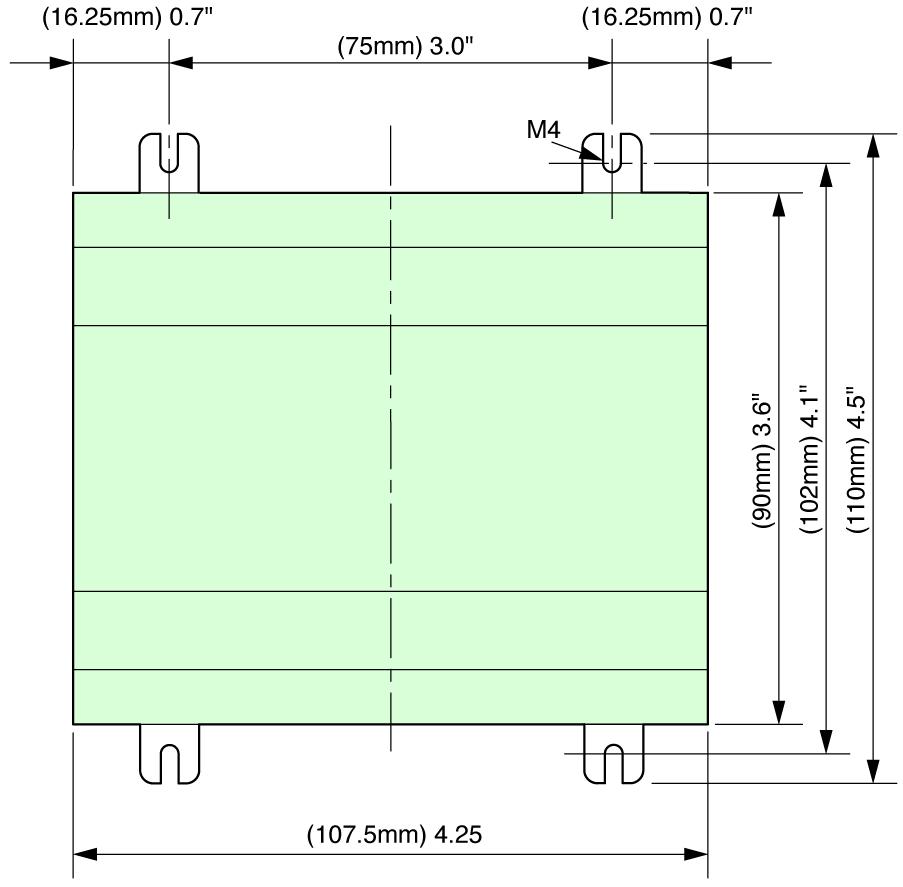

29 Dimensions All dimensions shown in inches (millimeters) 01/029 EASY2... EASY4... EASY6... EASY8..
4/0 EASY control relay
 4/0 DEL ALT ESC OK Contents 4/1 Page System overview 4/2 4/4 EASY800 networking 4/4 4/5 Basic units 4/5 Expansion units 4/9 Multi-function display 4/8 Display/operator unit 4/8 Power supply/cpu modules
002 Easy Control Relays System Overview
 002 Easy Control System Overview 1 1 3 2 4 3 5 7 6 5 8 6 7 9 Easy Control System Overview 003 Basic units 1 AC or DC operated Power supply AC 100 (115) 240 V, 50/60 Hz DC 24 V DC DA 12 V DC 8 or 12 digital
Select Pico Controllers, I/O and Accessories
 14 Pico and Pico GFX-70 Programmable Controllers Select Pico Controllers, I/O and Accessories Pico Controllers Select Pico controllers for up to 20 I/O points. Add a Pico expansion I/O module for up to
Pico Accessories. Memory Modules. This section provides information on various accessories.
 Pico and Pico GFX-70 Programmable Controllers 15 Table 3 Pico Expansion I/O Module Selection Cat. No. Input Voltage Category Number of Inputs Number of Outputs (Digital) 1760-IA12XOW6I 120 / 240V ac 12
DC562, digital input/output module,
 Ordering Data DATA SHEET DC562 Digital Input/Output Module 1 Ordering Data Part No. Description Product Life Cycle Phase *) 1SAP 231 900 R0000 1TNE 968 901 R3101 1TNE 968 901 R3102 1TNE 968 901 R3103 1TNE
Connectivity Solutions
 SmartWire-DT.1 System Overview Product Description.................................... Features............................................. System Overview Diagram............................... System
CM592 PROFIBUS Communication Module
 Ordering Data DATA SHEET CM592 PROFIBUS Communication Module 1 Ordering Data Part No. Description Product Life Cycle Phase *) 1SAP 173 200 R0001 1SAP 373 200 R0001 CM592-DP, communication module PROFIBUS
DX561 Digital Input/Output Module
 Ordering Data DATA SHEET DX561 Digital Input/Output Module 1 Ordering Data Part No. Description Product Life Cycle Phase *) 1TNE 968 902 R2301 1TNE 968 901 R3101 DX561, digital input/output module, 8 DI
Connectivity Solutions
 SmartWire-DT.1 System Overview Product Description.................................... Features............................................. System Overview Diagram............................... System
DC561, digital input/output module,
 Ordering Data DATA SHEET DC561 Digital Input/Output Module 1 Ordering Data Part No. Description Product Life Cycle Phase *) 1TNE 968 902 R2001 DC561, digital input/output module, 16 configurable inputs/outputs,
Connectivity Solutions. For Immediate Delivery or Tech Support call KMParts.com at (866) Contents.
 Contents.") .1 Connectivity Solutions Contents Description System Components.................... Contactor Modules..................... Pilot Device Modules.................... Technical Data and Specifications..........
.1 Connectivity Solutions Contents Description System Components.................... Contactor Modules..................... Pilot Device Modules.................... Technical Data and Specifications..........
Description Basic devices with positive operation contacts. Standards IEC/EN 60947, EN , VDE 0660, UL, CSA
 Delivery program Contactor relay, 3N/O+1N/C, DC current Part no. DILA-31(24VDC) Catalog No. 276379 Eaton Catalog No. XTRE10B31TD EL-Nummer 4130206 (Norway) Product range DILA relays Application Contactor
AO561 Analog Output Module
 Ordering Data DATA SHEET AO561 Analog Output Module 1 Ordering Data Part No. Description Product Life Cycle Phase *) 1TNE 968 902 R1201 AO561, analog output module, 2 AO, U/I 1TNE 968 901 R3102 Terminal
Safety relay emergency stop/protective door, 24VDC/AC, 4 enabling paths
 DATASHEET - ESR5-NO-41-24VAC-DC Safety relay emergency stop/protective door, 24VDC/AC, 4 enabling paths Part no. ESR5-NO-41-24VAC-DC Catalog No. 118701 EL-Nummer (Norway) 0004133317 Delivery program Product
AI561 Analog Input Module
 Ordering Data DATA SHEET AI561 Analog Input Module 1 Ordering Data Part No. Description Product Life Cycle Phase *) 1TNE 968 902 R1101 AI561, analog input module, 4 AI, U/I 1TNE 968 901 R3101 1TNE 968
Motor-protective circuit-breaker, 3p, Ir=16-25A, screw connection. Product range PKZM4 motor protective circuit-breakers up to 65 A
 DATASHEET - PKZM4-25 Delivery program Motor-protective circuit-breaker, 3p, Ir=16-25A, screw connection Part no. PKZM4-25 Catalog No. 222352 Eaton Catalog No. XTPR025DC1NL EL-Nummer 0004355158 (Norway)
Contact protection relay
 Contact protection relay Ordering details SVR 450 08 F0000 The protects sensitive control contacts from excessive load. It can be used with latching function or without. Bounce time of control contacts
DC522 Digital Input/Output Module
 Ordering Data DATA SHEET DC522 Digital Input/Output Module 1 Ordering Data Part No. Description Product Life Cycle Phase *) 1SAP 240 600 R0001 1SAP 440 600 R0001 DC522, digital input/output module, 16
Millenium 3. General Characteristics. General environment characteristics for CB, CD, XD, XR and XE product types
 Millenium 3 General Characteristics Millenium 3 Compact Range Millenium 3 Expandable Range Millenium 3 Communication Options Millenium 3 Range General environment characteristics for CB, CD, XD, XR and
Pico Accessories. Memory Modules. This section provides information on various accessories.
 Pico and Pico GFX-70 Programmable Controllers 15 Table 3 Pico Expansion I/O Module Selection Cat. No. Input Voltage Category Number of Inputs Number of Outputs (Digital) 1760-IA12XOW6I 120 / 240V ac 12
DI561 Digital Input Module
 Ordering Data DATA SHEET DI561 Digital Input Module 1 Ordering Data Part No. Description Product Life Cycle Phase *) 1TNE 968 902 R2101 1TNE 968 901 R3101 1TNE 968 901 R3103 1TNE 968 901 R3105 DI561, digital
DC541 Digital Input/Output Module
 Ordering Data DATA SHEET DC541 Digital Input/Output Module 1 Ordering Data Part No. Description Product Life Cycle Phase *) 1SAP 270 000 R0001 1SAP 470 000 R0001 DC541-CM, digital input/output module,
TF501, TF521 Terminal Bases
 Ordering Data DATA SHEET TF501, TF521 Terminal Bases 1 Ordering Data Part No. Scope of delivery Product life cycle status 1SAP 117 000 R0271 1SAP 317 000 R0271 1SAP 117 200 R0271 1SAP 317 200 R0271 TF501-CMS,
CI542 PROFIBUS Communication Interface Module
 Ordering Data DATA SHEET CI542 PROFIBUS Communication Interface Module 1 Ordering Data Part No. Description Product Life Cycle Phase *) 1SAP 224 200 R0001 1SAP 424 200 R0001 CI542-DP, PROFIBUS DP bus module,
AI531 Analog Input Module
 Ordering Data DATA SHEET AI531 Analog Input Module 1 Ordering Data Part No. Description Product Life Cycle Phase *) 1SAP 250 600 R0001 AI531, analog input module, 8 AI, U/I/Pt100, TC, 15 bits + sign, 4-wires
EZ Intelligent Relay. Product Focus
 EZ Intelligent Relay Product Focus Easy operation with maximum benefits The Eaton EZ intelligent relays provide basic functions that users could only implement previously with individually installed and
Monitoring technique. VARIMETER Voltage relay MK 9064N, MH 9064
 Monitoring technique VARIMETER Voltage relay MK 9064N, MH 9064 0269462 Your Advantages Preventive maintenance For better productivity Quicker fault locating Precise and reliable Min-, Max. value or window
Part No. Description Product Life Cycle Phase *) unit, 24 VDC, spring terminals. unit, 24 VDC, spring terminals, XC version
 unit, 24 VDC, spring terminals. unit, 24 VDC, spring terminals, XC version") Ordering Data DATA SHEET TU520 Terminal Unit 1 Ordering Data Part No. Description Product Life Cycle Phase *) 1SAP 214 400 R0001 1SAP 414 400 R0001 TU520-ETH, PROFINET I/O terminal unit, 24 VDC, spring
Ordering Data DATA SHEET TU520 Terminal Unit 1 Ordering Data Part No. Description Product Life Cycle Phase *) 1SAP 214 400 R0001 1SAP 414 400 R0001 TU520-ETH, PROFINET I/O terminal unit, 24 VDC, spring
DI572 Digital Input Module
 Ordering Data DATA SHEET DI572 Digital Input Module 1 Ordering Data Part No. Description Product Life Cycle Phase *) 1SAP 230 500 R0000 1TNE 968 901 R3101 1TNE 968 901 R3102 1TNE 968 901 R3103 1TNE 968
AX522 Analog Input/Output Module
 Ordering Data DATA SHEET AX522 Analog Input/Output Module 1 Ordering Data Part No. Description Product Life Cycle Phase *) 1SAP 250 000 R0001 1SAP 450 000 R0001 AX522, analog input/output module, 8 AI
AO523 Analog Input Module
 Ordering Data DATA SHEET AO523 Analog Input Module 1 Ordering Data Part No. Description Product Life Cycle Phase *) 1SAP 250 200 R0001 1SAP 450 200 R0001 AO523, analog output module, 16 AO, U/I, 12 bits
CM597 Ethernet Communication Module
 Ordering Data DATA SHEET CM597 Ethernet Communication Module 1 Ordering Data Part No. Description Product Life Cycle Phase *) 1SAP 173 700 R0001 1SAP 373 700 R0001 CM597-ETH, communication module Ethernet
DC532-XC, digital input/output module,
 Ordering Data DATA SHEET DC532 Digital Input/Output Module 1 Ordering Data Part No. Description Product Life Cycle Phase *) 1SAP 240 100 R0001 1SAP 440 100 R0001 DC532, digital input/output module, 16
SIMOCODE 3UF Motor Management and Control Devices
 Technical specifications General data applicable to the basic units, current measuring modules, current/voltage measuring modules, expansion modules, decoupling module and operator panel Permissible ambient
TU531, TU532 Terminal Unit
 Ordering Data DATA SHEET TU531, TU532 Terminal Unit 1 Ordering Data Part No. Description Product Life Cycle Phase *) 1SAP 217 200 R0001 1SAP 217 000 R0001 1SAP 417 000 R0001 TU531, terminal unit, 230 VAC,
02/11/2015
 35 mm - 1 Relay 8A OUR1 Part number 88867105 Multi-function or mono-function Multi-range Multi-voltage Relay output 1 or 2 : 8 A - 250 V (10 A UL) LED status indicator Option of connecting an external
Programmable Relay ZEN V2 Units
 Programmable Relay ZEN V2 Units Please read and understand this catalog before purchasing the products. Please consult your OMRON representative if you have any questions or comments. Refer to Warranty
ATV930U30M3 variable speed drive - ATV930-3kW - 200/240Vwith braking unit - IP21
 Characteristics variable speed drive - ATV930-3kW - 200/240Vwith braking unit - IP21 Main Range of product Product or component type Device application Device short name Variant Product destination Mounting
Electronic timer CT-ARS.11
 2CDC 251 088 F0t07 Features Rated control supply voltage 24 240 V AC/DC Single function OFF delay timer without auxiliary voltage One device includes 7 time ranges (0.05 s 10 min) 1 c/o (SPDT) contact
ILBPB24DO32. Inline Block IO Module for PROFIBUS With 32 Digital Outputs. AUTOMATIONWORX Data Sheet 6889_en_04. Description
 Inline Block IO Module for PROFIBUS With 32 Digital Outputs AUTOMATIONWORX Data Sheet 6889_en_04 Description PHOENIX CONTACT - 03/2007 & & ' ) The ILB PB 24 DO32 module is designed for use within a PROFIBUS
CD522 Encoder, Counter and PWM Module
 Ordering Data DATA SHEET CD522 Encoder, Counter and PWM Module 1 Ordering Data Part No. Description Product Life Cycle Phase *) 1SAP 260 300 R0001 1SAP 460 300 R0001 CD522, encoder & PWM module, 2 encoder
TM221M16R controller M IO relay
 Product data sheet Characteristics TM221M16R controller M221 16 IO relay Complementary Main Discrete I/O number 16 Number of I/O expansion module Supply voltage limits Inrush current Power consumption
TM241C40U controller M IO transistor NPN
 Characteristics controller M241 40 IO transistor NPN Main Range of product Product or component type [Us] rated supply voltage 15/12/2018 Modicon M241 Logic controller 24 V DC Discrete input number 24
CI541 PROFIBUS Communication Interface Module
 Ordering Data DATA SHEET CI541 PROFIBUS Communication Interface Module 1 Ordering Data Ordering No. Scope of delivery Product Life Cycle Phase *) 1SAP 224 100 R0001 1SAP 424 100 R0001 CI541-DP, PROFIBUS
TM241C24T controller M IO transistor PNP
 Characteristics controller M241 24 IO transistor PNP Main Range of product Product or component type [Us] rated supply voltage Feb 13, 2018 Modicon M241 Logic controller 24 V DC Discrete input number 14
Electronic timer CT-ERS.21
 2CDC 251 057 F0t07 Features Rated control supply voltage 24 240 V AC/DC Single function ON delay timer One device includes 10 time ranges (0.05 s 300 h) 2 c/o contacts 2 LEDs for status indication Width
XPSMF35. Product data sheet Characteristics. Preventa safety PLC compact - Profibus DP protocol. Main. Complementary. Safety module name
 Product data sheet Characteristics XPSMF3542 Preventa safety PLC compact - Profibus DP protocol Main Range of product Product or component type Safety module name Safety module application Nov 13, 2018
TM241C40R controller M IO relay
 Characteristics controller M241 40 IO relay Main Range of product Product or component type [Us] rated supply voltage Mar 09, 2017 Modicon M241 Logic controller 100...240 V AC Discrete input number 24
Safety relay emergency stop/protective door, 24V-230VDC/AC, 3 enabling paths
 DATASHEET - ESR5-NO-31-AC-DC Delivery program Safety relay emergency stop/protective door, 24V-230VDC/AC, 3 enabling paths Part no. ESR5-NO-31-AC-DC Catalog No. 118704 Eaton Catalog No. ESR5-NO-31-AC-DC
Safety relay emergency stop/protective door, 230VAC, 3 enabling paths
 DATASHEET - ESR5-NO-31-230VAC Safety relay emergency stop/protective door, 230VAC, 3 enabling paths Part no. ESR5-NO-31-230VAC Catalog No. 119380 EL-Nummer (Norway) 4133320 Delivery program Product range
TM221M32TK controller M IO transistor PNP
 Characteristics controller M221 32 IO transistor PNP Main Range of product Product or component type [Us] rated supply voltage Discrete input number Analogue input number Discrete output type Discrete
Electronic timer CT-AHD.22
 2CDC 251 093 F0t06 a Rotary switch for the preselection of the time range b Potentiometer with direct reading scale for the fine adjustment of the time delay c U: green LED V control supply voltage applied
AX521 Analog Input/Output Module
 Ordering Data DATA SHEET AX521 Analog Input/Output Module 1 Ordering Data Part No. Description Product Life Cycle Phase *) 1SAP 250 100 R0001 1SAP 450 100 R0001 AX521, analog input/output module, 4 AI,
Electronic timer CT-ERS.12 ON-delayed with 1 c/o contact Data sheet
 2CDC 251 056 F0t07 Features Rated control supply voltage 24-48 V DC, 24-240 V AC Single-function ON-delay timer One device includes 10 time ranges (0.05 s - 300 h) 1 c/o contact 2 LEDs for status indication
TM241CEC24R controller M IO relay Ethernet CAN master
 Characteristics controller M241 24 IO relay Ethernet CAN master Main Range of product Product or component type [Us] rated supply voltage Nov 28, 2017 Modicon M241 Logic controller 100...240 V AC Discrete
RTU500 series Data Sheet Power Supply CP-E 24/2.5
 Data Sheet Power Supply CP-E 24/2.5 Power Supply CP-E 24/2.5 Application The primary switch mode power supply offers two voltage input ranges. This enables the supply with AC or DC. Furthermore it is equipped
DA502 Digital/Analog Input/Output Module
 Ordering Data DATA SHEET DA502 Digital/Analog Input/Output Module 1 Ordering Data Part No. Description Product Life Cycle Phase *) 1SAP 250 800 R0001 1SAP 450 800 R0001 DA502, digital/analog input/ output
TM221M16TG controller M IO transistor PNP spring
 Characteristics controller M221 16 IO transistor PNP spring Main Range of product Product or component type [Us] rated supply voltage Discrete input number Analogue input number Discrete output type Discrete
Electronic timer CT-ARS.21 OFF-delayed without auxiliary voltage with 2 c/o (SPDT) contacts
 contacts") Data sheet Electronic timer CT-ARS.21 OFF-delayed without auxiliary voltage with 2 c/o (SPDT) contacts The CT-ARS.21 is an electronic timer from the CT-S range with true OFF-delay. It provides 7 time ranges
Data sheet Electronic timer CT-ARS.21 OFF-delayed without auxiliary voltage with 2 c/o (SPDT) contacts The CT-ARS.21 is an electronic timer from the CT-S range with true OFF-delay. It provides 7 time ranges
CM589 PROFINET Communication Module
 Ordering Data DATA SHEET CM589 PROFINET Communication Module 1 Ordering Data Part No. Description Product Life Cycle Phase *) 1SAP 172 900 R0011 1SAP 372 900 R0011 1SAP 172 900 R0111 1SAP 372 900 R0111
XC-CPU-201 XC-CPU-201-XV
 / XC-CPU- XC-CPU--XV Ethernet integrated The / MBit Ethernet interface of the XC offers the perfect link to IT communication. Whether you need rapid access to programs, high-speed data exchange between
CM579-PNIO PROFINET Communication Module
 Ordering Data DATA SHEET CM579-PNIO PROFINET Communication Module 1 Ordering Data Part No. Description Product Life Cycle Phase *) 1SAP 170 901 R0101 1SAP 370 901 R0101 CM579-PNIO, PROFINET communication
Electronic timer CT-ERD.12
 2CDC 251 092 F0t06 a Rotary switch for the preselection of the time range b Potentiometer with direct reading scale for the fine adjustment of the time delay c U: green LED V control supply voltage applied
CI504 PROFINET Communication Interface Module
 Ordering Data DATA SHEET CI504 PROFINET Communication Interface Module 1 Ordering Data Part No. Description Product Life Cycle Phase *) 1SAP 221 300 R0001 1SAP 421 300 R0001 CI504-PNIO, PROFINET Bus Module
Electronic timer CT-EBD.12 Flasher starting with ON with 1 c/o (SPDT) contact
 contact") Data sheet Electronic timer CT-EBD.12 Flasher starting with ON with 1 c/o (SPDT) contact The CT-EBD.12 is an electronic time relay with the function flasher starting with ON. It is from the CT-D range.
Data sheet Electronic timer CT-EBD.12 Flasher starting with ON with 1 c/o (SPDT) contact The CT-EBD.12 is an electronic time relay with the function flasher starting with ON. It is from the CT-D range.
CM589 PROFINET Communication Module
 Ordering Data DATA SHEET CM589 PROFINET Communication Module 1 Ordering Data Part No. Description Product Life Cycle Phase *) 1SAP 172 900 R0011 1SAP 372 900 R0011 1SAP 172 900 R0111 1SAP 372 900 R0111
ATV930D22M3 variable speed drive - ATV930-22kW - 200/240V- with braking unit - IP21
 Characteristics variable speed drive - ATV930-22kW - 200/240V- with braking unit - IP21 Main Range of product Product or component type Device application Device short name Variant Product destination
Installation / control / monitoring technique. CANopen PLC IL 5504, IN 5504 minimaster
 Installation / control / monitoring technique CANopen PLC IL, IN minimaster 6 Circuit diagram CAN H Rab C CAN L C IL IN C CAN H Rab CAN L C According to IEC/EN 6 -, EN 78 Operation as master - Operation
PHOENIX CONTACT - 07/2006
 Buffer module with maintenance-free capacitor-based power storage device INTERFACE Data sheet 102035_03_en PHOENIX CONTACT - 07/2006 Description Short-term mains interruptions are bridged by QUINT BUFFER,
XPSMF40. Main. Safety module name. Monitoring safety detection discrete input Monitoring safety dialogue discrete output
 Product datasheet Characteristics XPSMF4000 Preventa safety PLC compact - Safe Ethernet Main Range of product Product or component type Safety module name Safety module application Preventa Safety automation
9.1. Connectivity Solutions
 .1 Pilot Device Modules Contents Description System Components....................... System Controllers........................ Contactor Modules........................ Pilot Device Modules Product Identification....................
MIC-2 MKII, Multi-instrument DATA SHEET
 MIC-2 MKII, Multi-instrument DATA SHEET Measurements All 3-phase AC measurements True RMS 4-Quadrant energy Power Quality Analysis Replaces analogue meters RS-485 Modbus RTU protocol TCP/IP Modbus (optional)
TM241CE40R controller M IO relay Ethernet
 Product data sheet Characteristics TM241CE40R controller M241 40 IO relay Ethernet Complementary Main Discrete I/O number 40 Discrete input logic Discrete input voltage Discrete input voltage type Voltage
TM221CE24R controller M IO relay Ethernet
 Product data sheet Characteristics TM221CE24R controller M221 24 IO relay Ethernet Complementary Main Discrete I/O number 24 Number of I/O expansion module Supply voltage limits Network frequency Inrush
Installation / Control / Monitoring Technique
 Installation / Control / Monitoring Technique MINIMASTER CANopen PLC IL, IN 6 Your Advantages Compact CAN-operation Graphical programming Qquick and easy installation Various input- / output module digital
Voltage monitoring relays CM-ESS.1 For single-phase AC/DC voltages
 Data sheet Voltage monitoring relays CM-ESS.1 For single-phase AC/DC voltages The CM-ESS.1 is an electronic voltage monitoring relay that provides reliable monitoring of voltages as well as detection of
Electronic timer CT-ARS.11 OFF-delayed without auxiliary voltage with 1 c/o (SPDT) contact
 contact") Data sheet Electronic timer CT-ARS.11 OFF-delayed without auxiliary voltage with 1 c/o (SPDT) contact The CT-ARS.11 is an electronic timer from the CT-S range with true OFF-delay. It provides 7 time ranges
Data sheet Electronic timer CT-ARS.11 OFF-delayed without auxiliary voltage with 1 c/o (SPDT) contact The CT-ARS.11 is an electronic timer from the CT-S range with true OFF-delay. It provides 7 time ranges
FEATURES DESCRIPTION FEATURES
 FEATURES Two High Speed Counters Two Pulse Train Outputs Two Pulse Width Modulation Outputs 24 Sinking or Sourcing Inputs 16 Outputs 1 RS232 Port 2 RS485 Ports Supports Modbus RTU Protocol Communicate
Installation / control / monitoring technique. CANopen PLC IL 5504, IN 5504 minimaster
 Installation / control / monitoring technique CANopen PLC IL, IN minimaster 6 Circuit diagram CAN H Rab CAN H CAN CAN L GND C C CAN L C C Rab M88_a IL IN CAN H CAN H Rab CAN CAN L GND C C Rab CAN L C C
Installation / Control Technique
 Installation / Control Technique Interface Relay, Interface Relay System Input-Output Interface Relay IK 3070, I_ 3070 0633 IK 3070 Circuit Diagrams IS 3070 According to IEC/EN 61 810-1 Relay, triac or
02/11/2015
 DIN Rail Mount 22.5 mm TU2R1 Part number 88865305 Product with 1 relays (88 865 100/103/105/115/125/135/145/155/185/503) : Replaced by the 17,5 mm range For instance : previous part number 88 865 XXX /
08/07/2015
 DIN Rail Mount 22.5 mm TUR1 Part number 88865105 Product with 1 relays (88 865 100/103/105/115/125/135/145/155/185/503) : Replaced by the 17,5 mm range For instance : previous part number 88 865 XXX /
MINI-PS AC/10-15DC/8
 Primary-Switched Power Supply, Narrow Design Data Sheet 08/2004 MINI POWER provides: An extra narrow design, with widths of 22.5 mm, 45 mm, and 67.5 mm (0.886, 1.772, and 2.657 in.) Global use due to a
TM241CEC24T. Main. 14 (remote I/O architecture) W with max number of I/O expansion module ma fast input. 2.
 W with max number of I/O expansion module ma fast input. 2.") Product datasheet Characteristics TM241CEC24T Main Range of product Product or component type [Us] rated supply voltage Discrete input number Discrete output type Discrete output number Discrete output
Product datasheet Characteristics TM241CEC24T Main Range of product Product or component type [Us] rated supply voltage Discrete input number Discrete output type Discrete output number Discrete output
Thermistor motor protection relays CM-MSS.12 and CM-MSS.13
 Data sheet Thermistor motor protection relays CM-MSS.12 and CM-MSS.13 The thermistor motor protection relays CM-MSS.12 and CM-MSS.13 monitor the winding temperature of motors and protect them from overheating,
TM241CE24T controller M IO transistor PNP Ethernet
 Product data sheet Characteristics TM241CE24T controller M241 24 IO transistor PNP Ethernet Complementary Main Discrete I/O number 24 Number of I/O expansion module Supply voltage limits Inrush current
CI521 Modbus Communication Interface Module
 Ordering Data DATA SHEET CI521 Modbus Communication Interface Module 1 Ordering Data Part No. Description Product Life Cycle Phase *) 1SAP 222 100 R0001 1SAP 422 100 R0001 CI521-MODTCP, Modbus TCP bus
OTB1C0DM9LP I/O distributed module OTB - CANopen bus m
 Characteristics I/O distributed module OTB - CANopen bus - 0..1000 m Main Range of product Product or component type Integrated connection type Bus type Jan 28, 2018 Modicon OTB I/O distributed module
TM221ME32TK controller M IO transistor PNP Ethernet
 Product data sheet Characteristics TM221ME32TK controller M221 32 IO transistor PNP Ethernet Complementary Main Discrete I/O number 32 Number of I/O expansion module Supply voltage limits Inrush current
QUINT-BUFFER/24DC/24DC/40
 Buffer module Data sheet 105496_en_01 PHOENIX CONTACT 2013-11-01 1 Description The QUINT BUFFER buffer module combines the electronic switchover unit and power storage in the same housing. The buffer module
DA502 Digital/Analog Input/Output Module
 Ordering Data DATA SHEET DA502 Digital/Analog Input/Output Module 1 Ordering Data Part No. Description Product Life Cycle Phase *) 1SAP 250 800 R0001 1SAP 450 800 R0001 DA502, digital/analog input/output
DA502 Digital/Analog Input/Output Module
 Ordering Data DATA SHEET DA502 Digital/Analog Input/Output Module 1 Ordering Data Part No. Description Product Life Cycle Phase *) 1SAP 250 800 R0001 1SAP 450 800 R0001 DA502, digital/analog input/ output
IB ST 24 AO 4/EF. INTERBUS-ST analog output module, 4 outputs, 0-10 V, ±10 V, 0-20 ma, 4-20 ma. Data sheet. 1 Description
 INTERBUS-ST analog output module, 4 outputs, 0-10 V, ±10 V, 0-20 ma, 4-20 ma Data sheet 105597_en_01 PHOENIX CONTACT 2014-10-24 1 Description The module is designed for use within an ST station. It is
RIC PROGRAMMABLE INTELLIGENT CONTROLLER
 Section F PROGRAMMABLE INTELLIGENT CONTROLLER intelligent controller is a new type of programmable controller. It is programmed by the use of a Function Block Diagram. The programming of is easier to learn
New Products Catalogue SmartWire-Darwin. The easy way to connect. The easy way to connect.
 Darwin Technology www.moeller.net New Products Catalogue 2009 The easy way to connect. The easy way to connect. . Evolution in the control panel. Controlling Manufacturers of machines and systems strive
ATV32HU11M2437 variable speed drive ATV32-1.1kW 200V - 1P - Bluetooth built-in - w heat sink
 Characteristics variable speed drive ATV32-1.1kW 200V - 1P - Bluetooth built-in - w heat sink Main Range of product Altivar 32 Product or component type Product destination Product specific application
TM241CE24T controller M IO transistor PNP Ethernet
 Characteristics controller M241 24 IO transistor PNP Ethernet Product availability : Stock - Normally stocked in distribution facility Price* : 479.00 USD Main Range of product Product or component type
TM241CE40R controller M IO relay Ethernet
 Characteristics controller M241 40 IO relay Ethernet Main Range of product Product or component type [Us] rated supply voltage Apr 10, 2018 Modicon M241 Logic controller 100...240 V AC Discrete input number
TM241CE40R controller M IO relay Ethernet
 Characteristics controller M241 40 IO relay Ethernet Product availability : Stock - Normally stocked in distribution facility Price* : 559.00 USD Main Range of product Product or component type [Us] rated
TM241CE40R controller M IO relay Ethernet
 Characteristics controller M241 40 IO relay Ethernet Main Range of product Product or component type [Us] rated supply voltage Mar 09, 2017 Modicon M241 Logic controller 100...240 V AC Discrete input number