Programmable Controllers
|
|
|
- Bathsheba Butler
- 6 years ago
- Views:
Transcription
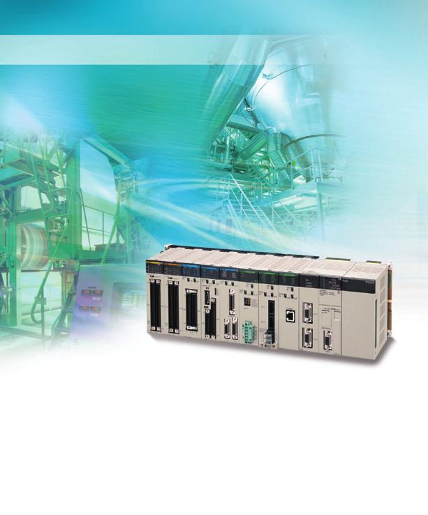
1 Programmable Controllers
2 Multi-application Controllers: From High-performance Machine C Highly Reliable Process Control Ultimate Controller Performance User-friendly Development Environment In order to create facilities that have the production capability to withstand sudden changes in demand, or to create machinery that is easily distinguished from that created by market competitors, a top-speed controller that can deliver the performance required to support these needs is required. The PLCs have been equipped with the highest I/O responsiveness and data control functionality to significantly reduce processing time and to control machinery movement with greater precision. In order to allow easier development of complex programs, bin addition to an integrated Windows-based development environment, the new PLCs are equipped with a variety of instructions. Structured programming functionality has been improved to allow programs to be reused with greater efficiency and thereby reduce labor requirements and cut costs. 2 F-2 Windows is a registered trademark of Microsoft Corporation in the ed States and other countries. Microsoft product screen shots reprinted with permission from Microsoft Corporarion. Other company names and product names in this document are the trademarks or registered trademarks of their respective companies.


3 Concepts... F-2 ontrol to System Design Guide...1 System Configuration...2 Dimensions/Mounting Dimensions...9 General...11 Common for CPU s...12 Consumption for Power Supply s...15 Ordering Information...17 Basic Configuration s...18 Programming Devices...22 Optional Products and Maintenance Products...25 DIN Track Accessories...25 Basic I/O s...26 Special I/O s and CPU Bus s...32 Replacing C200H I/O s...54 Efficient Use of Valuable Assets The know-how that our customers have accumulated through the years forms the core of their competitive strength. At OMRON, we believe in enhancing this knowhow to the utmost. The key to doing this is 100% upward compatibility. PLCs allow existing s and programs to be used without any changes. F-3

4 Use the improved PLCs to scale advanced s to the optimum size. 1 Wide Lineup Makes It Easy to Build the Optimum System A total of nine CPU models provide for Communications Boards, and a wide a wide range of applications, from selection of Special I/O s that can be small-scale s to large. The lineup used with any CPU s to flexibly build the also includes Memory Cards, Serial that meets the requirements. Product lineup (Example: LD instruction processing speed, DM capacity) Program Capacity 250 K steps (LD: 0.02 µs, DM: 448 K) 120 K steps 60 K steps (LD: 0.02 µs, DM: 256 K) (LD: 0.02 µs, DM: 128 K) (LD: 0.04 µs, DM: 128 K) 30 K steps (LD: 0.04 µs, DM: 64 K) (LD: 0.02 µs, DM: 64 K) 20 K steps (LD: 0.04 µs, DM: 64 K) (LD: 0.02 µs, DM: 64 K) 10 K steps (LD: 0.04 µs, DM: 64 K) 960 pts 1,280 pts 5,120 pts Number of I/O points Two Series of s Up to 50 m Long for Long-distance with Up to 72 s and 7 s With an expansion capacity of up to 80 s and 7 s over a distance of 12 meters, the can meet large-scale control needs. Alternatively, an I/O Control and I/O Interface s can be used to connect two series of Longdistance s extending up to 50 m each and containing a total of up to 72 s and 7 s. Basic I/O s, Special I/O s, and CPU Bus s can be mounted anywhere on the s and programmed without being concerned about special remote programming requirements. 50 m I/O Control 9 s CPU 2 Series of s; Up to 7 s Total I/O Interface Terminating Resistor 50 m Note: C200H s cannot be mounted on the Longdistance s. F-4

5 Control Up to 960 Points with s Mounted to the CPU The provides a high level of space efficiency. As many as 960 I/O points can be controlled by simply mounting ten Basic I/O s, with 96 I/O points each, to the CPU. Alternatively, as many as 80 analog I/O points can be used by mounting five Analog Input s and five Analog Output s. Ten I/O s of 96 points each Five Analog Output s of 8 points each Five Analog Input s of 8 points each Improved Refresh Performance for Data Links, Remote I/O Communications, and Protocol Macros In the past, I/O refresh processing with the CPU Bus only occurred during I/O refresh after instructions were executed. With the new, however, I/O can be refreshed immediately by using the DLNK instruction. Immediate refreshing for processes peculiar to the CPU Bus, such as for data links and DeviceNet remote I/O communications, and for allocated CIO Area/DM Area when instructions are executed, means greater refresh responsiveness for CPU Bus s. CPU DLNK n CIO Area allocated to CPU Bus s DM Area allocated for CPU Bus s Specific Area for CPU Bus s name Controller Link DeviceNet Serial Communications Ethernet Immediate I/O refresh CPU Bus n Data exchange during communications cycle Refresh function Data links Remote I/O Protocol macros Socket service based on manipulation of specific bits. Large Capacity CPU s for Greater Component Control Power The CPU s boast amazing capacity with up to 5,120 I/O points, 250 Ksteps of programming, 448 K of data memory (including expanded data memory) and 4,096 timers/counters each. With a large programming capacity, PLCs are not only ideal for large-scale s but easily handle value-added applications and other advanced data processing. Reduced Variation in Cycle Time During Data Processing Instructions that require long execution time, processed over multiple cycles to minimize such as table data processing instructions variations in cycle time and maintain stable and text string processing instructions, are I/O response. Table data/ text string processing Long execution time Table data/ text string processing Only start of processing designated. System Bus Baud Rate Doubled The data transfer rate between the CPU and certain s has been doubled to further improve total performance. Baud rate doubled System bus The cycle is temporarily extended when the instruction is executed. Variation Background processing performed over several cycles to limit the impact on cycle time and thus reduce variation in cycle time. Faster Instruction Execution and Faster Overall Performance In addition to further improvements to the performance in the industry. Also, the new instruction execution engine, which is the models have a mode where instruction core of overall PLC performance, the execution and peripheral processing are high-speed RISC chip has been upgraded to processed in parallel, enabling balanced realize the fastest instruction execution improvements in overall speed. Special I/O CPU Common Processing PCMIX Value 0.3 ms 16 Cycle time for 128 inputs Cycle Time ( ) and 128 outputs Basic instructions only: 38 Ksteps/ms Including special instructions: 22 Ksteps/ms LD Instruction Processing Speed OUT Instruction Processing Speed Subroutine Processing Speed 20 ns 20 ns 2.1 µs F-5
6 Equipped with functions demanded by the production site to suit a variety of applications 2 Nested Interlocks (for CPU Ver. 2.0 or Later) Although strictly speaking the present interlock instructions do not allow nesting, applications can be created to include combination of complete and partial interlock Emergency stop button Conveyor operates MILH 0 conditions that achieve nested interlocks. Worker present (a) MILH 1 Emergency stop button Operator Contact a Product added by contact a Product added MILC 1 MILC 0 (1) Conveyor operates (2) Contact "a" turns ON when operator is present and products are supplied. (3) When the emergency stop button is pressed, the conveyor and product addition both stop. CX-Programmer Screen Support Software clearly shows the interlock status. Easy Cam Switch Control with Ladder Instructions (for CPU Ver. 2.0 or Later) Absolute encoder Parallel wiring Cam switch GRY Gray code converted into binary, BCD, or angles. Angular data Value converted by GRY instruction + Comparison table Upper limit Lower limit Compared using BCMP2 instruction BCMP2 Compared to see whether data is between upper and lower limits. Output ON OFF OFF ON OFF * The time interval for execution by the GRY instruction is determined by the response speed for reading data from the absolute encoder. Easy Calendar Timer Function (for CPU Ver. 2.0 or Later) TIME-PROPORTIONAL OUTPUT (TPO) Instruction (for CPU Ver. 2.0 or Later) =DT Turn ON at 5:00 every evening Compares two dates/times Comparison can be limited to any combination of years, months, days, hours, minutes, or seconds. Example: A calendar timer function can be easily set up to start a process at exactly 5:00 every evening. SSR 20% 80% 1 s PID S C D TPO S C B Manipulated variable Time-proportioning PID control can be handled by the PLC by combining the PID and TPO (TIME-PROPORTIONAL OUTPUT) instructions. F-6
7 . Convert Between Floating-point Decimal and Character Strings The new can convert floating-point The new can convert ASCII character decimal (real numbers) to character strings strings read from measurement devices by (ASCII) for display on a PT (operator serial communications to floating-point interface). The data can be displayed on the decimal data for use in data processing. PT as a character string display element. PT Measurement device (example) Floatingpoint decimal E.g., Conversion instruction Character string E Character-string display element Conversion instruction Character Floatingpoint string decima Serial communications Simpler Ladder Programs Ladder programs that use a lot of basic instructions can be simplified using differentiation instructions LD NOT, AND NOT, and OR NOT, and instructions that access bits in the DM and EM Areas. With other PLCs With -series PLCs a a PID Autotuning The new can autotune PID constants with a PID control instruction. The limit cycle method is used for autotuning, so the tuning is completed quickly. This is particularly effective for multiple-loop PID control. Highly Accurate Positioning with XY Tables The new has many doubleprecision processing instructions for floating-point decimal operations, enabling positioning with greater accuracy. a a ORW D00000 #0001 D00000 ANDW D00000 #FFFE D00000 OUTB D00000 #0000 PIDAT Autotuning for PID constants (limit cycle method) PID control instruction with autotuning Error Status Generation for Debugging A specified error status can be simulated by executing the diagnostic instructions (FAL/FALS). With the new, debugging is simple for applications that display messages on a PT or other display device based on the error status of the CPU. (Example) An error has occurred at unit number xx. There is a possibility that rack number xx is disconnected. PT Error in Special I/O PT FAL Floating-point decimal instruction High-precision positioning Easy Reading of Maintenance Data via Componet/DeviceNet The addition of special explicit message instructions makes it easy to send explicit messages without having to consider FINS commands. Transferring data among PLCs with explicit messages is also simplified. DeviceNet CompoNet Special explicit message instruction No need to consider FINS Binary Set Values for Timer/Counter Instructions The SV for a timer or counter instruction can be specified using either BCD or binary. Using binary SV enables longer timers and higher-value counters. Examples: Timer/Counter Instructions TIM (BCD): 0 to s TIMX (550) (binary) 0 to s CNT (BCD): 0 to 999 counts CNTX (546) (binary) 0 to 65,535 counts [Applicable Instructions] Timer/Counter Instructions TIMER: TIMX (550) COUNTER: CNTX (546) HIGH-SPEED TIMER: TIMHX (551) ONE-MS TIMER: TMHHX (552) ACCUMULATIVE TIMER: TTIMX (555) LONG TIMER: TIMLX (553) MULTI-OUTPUT TIMER: MTIMX (554) REVERSIBLE COUNTER: CNTRX (548) RESET TIMER/COUNTER: CNRX (547) I/O bus error FALS (Supported for DeviceNet version 2.0 or later.) F-7


8 The CX-One FA Integrated Tool Package makes desig development, and maintenance easy and efficient. 3 Integrated OMRON PLCs and Component Support Software FA Integrated Tool Package The CX-One is an FA Integrated Tool Package for connecting, setting, and programming OMRON components, including PLCs. programming and settings can be done with just the CX-Programmer, but the CX-One provides Support Software for setting and programming PTs, Temperature Controllers, and many other components. Using the CX-One makes programming and setup easy, shortening the total lead time required for starting up machines and equipment. CX-One Configuration Network Software PLC Software HMI Software Motion Control Software PLC-based Process Control Software CX-Integrator CX-FLnet CX-Protocol CX-Configurator FDT Network Configurator CX-Programmer CX-Simulator SwitchBox Utility CX-Designer The Ladder Monitor Software is included. (See note 1.) NV-Designer (See note 2.) CX-Drive CX-Motion-NCF CX-Motion-MCH CX-Position CX-Motion CX-Process Tool Face Plate Auto-Builder for NS Component Software for 6 CX-Thermo Temperature Controllers Note: 1. The Ladder Monitor is required to monitor ladder programs running on CS/CJ-series PLCs from an NS-series PT. 2. Include with CX-One Lite version 4.0 and in CX-One version 3.2 or later. Easy Programming Smart Input A complete range of intuitive programming functions is provided, including instruction and address input assistance, address incrementing, and address Incremental Copy. These functions enable waste-free programming with minimal effort. Instruction and Address Input Assistance When you begin typing an instruction from the keyboard while in the Ladder Editor Window, suggested instructions are displayed. All you have to do is select the instruction from the list for easy input even if you do not remember the entire mnemonic. Suggested instructions displayed Automatic Insertion of Connecting Lines When an output or application instruction is input, the required connecting line is inserted automatically starting at the cursor location. This greatly simplifies the work required to insert lines. Address Incremental Copy To create the same group of ladder instructions more than once, the address incremental copy function can be used to reuse the instructions simply by inputting an address offset. Also, address offsets can be set individually and I/O comments can be created automatically. F-8
9 n, Improved Programming Efficiency with Single-key Operation The CX-Programmer features the Single-key Concept to increase operability. Apart from inputs to ladder diagrams, history searches, and model jumps, single-key operation can be used for simulation debugging as well. Single-key Inputs The allocation of shortcut keys can be checked in the guidance for ladder input key operations. Key inputs, such as the Key for NO input conditions, the Key for OUTPUT instruction, and the Key for special instructions are convenient when programming. Just press the Key and enter the bit number and comment to complete the input condition. Special instruction can be input as shown in the following figure. Lines can be easily connected using key operations. Ctrl Single-key Searches and Jumps Search functions, such as Find Back (searching for input conditions or outputs with the same address) and Find Address can be executed with a single key. Single-key Simulation Simulation and debugging of a PLC program can also be executed with a single key. Applications using both a PLC and Programmable Terminal can be debugged using a computer without the actual devices using PLC-PT Integrated Simulation. Multiple Languages Can Be Combined To Make Programming Flexible The multilingual feature supports IEC Programming is possible in a language that is appropriate for the process by combining ladder diagram and ST languages. Function blocks can be created to make programming even more efficient. User program Task Task Task Task a : = a + 1; RESULTS=0.0; IF M=TRUE THEN RESULTS=SIN (date): ENDIF; Ladder diagram: Controls the equipment and external devices. Function Block FB (FB): Can be used and reused as modules. Structured Text (ST): Simplifies math calculations and character string processing. Sequential Function Charts (SFC): Controls the steps in processing. A programming language suitable for the process can be used. OMRON FB Library, SAP Ladder diagrams, communications programs, and control screens can be created simply by selecting and pasting program modules from the extensive libraries. Using FB and SAP modules to build the programs, it is possible to create programs that are easier to understand. Debugging Management of Multiple Networks The operation of networks with configurations consisting of multiple networks including PLC networks such as EtherNet/IP and Controller Link, field networks such as DeviceNet and CompoNet, and networks for Programmable Terminals and Serial Devices, can be restored simultaneously from the CX-One. Onsite start up and debugging can be conducted efficiently and without errors because PLCs and devices can be selected from the window to transfer programs and parameter data to the computer during operation. Icons for the simulation function can be accessed directly. Ladder diagram Monitoring for Multiple PLCs Multiple PLCs can be monitored by displaying them in series on the screen. This way it is easy to debug data links between PLCs and monitor the inputs and outputs of different PLCs. PLC1 PLC2 PLC3 Node 1 Node 2 Node 3 Batch Backup Batch Backup/Restore with a Computer A computer can be used to backup, compare, or restore data for all or specific PLC s when connected online. Backup information is automatically tagged with a date stamp. It is thus possible to return to the state before an error occurred. It is also easy to identify the file for restoring data when an error occurs. Specified backup destination folder PLC Backup Software CS/CJ-series PLC (CPU + Configuration s) CX-Integrator CX-Programmer Restore Compare Backup Time Require for Debugging and Maintenance Has Been Reduced with the Comprehensive Data Trace Function Functionality and operability has been significantly upgraded compared to the previous data trace function. The new data trace function provides comprehensive debugging, such as I/O comment display of sampled addresses, specification using symbols, checking the measurement time between two selected points, and layering waveforms. Furthermore, data sampled from the CPU s trace memory can be saved to a file on the computer at a specified frequency. This can be used as for long-term logging of data. Data Trace Function Sampled values from a specific word will be displayed. The traced waveforms can be displayed as layers. Sampled value from a specific input bit will be displayed. F-9
10 Further improvements to communications function Seamless networks increase production site trans 4 High-speed, High-capacity Data Links between PLCs via EtherNet/IP EtherNet/IP is supported. EtherNet/IP is a global-standard network that uses cutting-edge general Ethernet technology for control and information network integration. This enables data links between PLCs, data links between a PLC and multi-vendor devices, and communications between PLCs and PTs over a general Ethernet network. Functions for Better Ethernet Support Ethernet is becoming increasingly important standard for information networks. Up to eight socket interfaces for TCP/IP and UDP/IP are supported, in addition to FINS messages, FTP file transfers, and mail notification, so that production management can now be organically linked with the production site. CompoNet Greatly Advances Wiring Reductions, Greater Information Handling, and Standardization CompoNet is a multi-vendor network for bit-level control of approximately 1,000 points in 1.0 ms. It supports message communications at the sensor and actuator levels. Maintenance information can be controlled in each Slave for preventative maintenance of equipment. Information network Flexible System Building Based on the DeviceNet The Series supports the worldwide multivendor bus standard, DeviceNet. Component connections in a multivendor environment are greatly enhanced by connecting to up to 64 nodes for a wide range of FA applications, and by device profiles and configurator tools that ensure high reliability and easy maintenance. Production s can be configured even more flexibly by incorporating products such as the MULTIPLE I/O TERMINAL. Seamless Controller network CompoNet Master EtherNet/IP CompoNet Component network F-10
11 GRT1-TBL ID4 ID4 ID4 OD4 OD4 OD4 END GRT1-TBL ID4 ID4 ID4 OD4 OD4 OD4 END TS TS TS TS TS TS TS TS TS TS TS TS s. parency. The Solution for Communicating across Network Levels The enables FINS message seamless communications for communications across a maximum of eight sending FINS messages across multiple levels (See note.) (using CX-Programmer levels of Ethernet and Controller Link Ver. 4.0 or higher) in comparison with three networks. levels in previous OMRON s Note: For CPU Ver. 2.0 or later. up to eight levels lets you build a A Wide Range of Systems, from Small-scale to Large OMRON offers a full lineup of reliable PLCs including the "flagship" Series, and ranging from the small scale CP1H to the large-scale CV Series. The Series meets the needs not only of small-scale to large-scale s, but of distributed s as well. This allows the construction of the optimum for the scale and applications of the production site. Head office or remote office Web browser CX-Programmer Head office, remote office, home, business trip destination CX-Programmer FA Wireless LAN WE70 Ethernet and EtherNet/IP Ethernet and EtherNet/IP Ethernet and EtherNet/IP Controller Link EtherNet/IP Hub Controller Link NS Series V8 DeviceNet EtherNet/IP CompoNet Master Controller Link DeviceNet Controller Link DeviceNet CompoNet DeviceNet F-11
12 Construction of s in multi-vendor environm with Serial Gateway Function. 5 Serial Gateway (CPU Ver. 3.0 or later) (Serial Communications s/boards with Ver. 1.2 or later) Truly Seamless Incorporation of OMRON Components and Other Devices into Networks When the CPU (Ver. 3.0 or later) or Serial Communications Board or Serial Communications (Ver. 1.2 or later) receive a FINS command containing a CompoWay/F command (see note 1.) via network or serial communications, the command is automatically converted to a protocol suitable for the message and forwarded using serial communications. CompoWay/F (See note 2.) Host Link FINS (Possible only with Serial Communications s or Serial Communications Boards) Gateway Component/PLC FINS network Serial communications Note 1: FINS Abbreviation for Factory Interface Network Service. A command for message services common to OMRON networks. FINS commands can be sent across up to 8 network levels*, including serial communications paths using a serial gateway. (*Possible only with CS/CJ-series CPU Ver. 2.0 or later.) Note 2: CompoWay/F CompoWay/F is an integrated communications protocol used for OMRON general-purpose serial communications. It is used by Temperature Controllers, Digital Panel Meters, Timer/Counters, Smart Sensors, Cam Positioners, Safety Controllers, etc. (as of July 2004). Serial Gateway System (Reference) When CompoWay/F commands are enclosed in FINS commands and sent to Serial Communications Boards or Serial Communications s (Ver. 1.2) or serial ports on CPU Ver. 3.0, the enclosed CompoWay/F command is retrieved using a Serial Gateway Function and sent as a CompoWay/F command. FINS command received Serial Gateway: FINS command "capsule" opened and contents retrieved. Sent as a CompoWay/ F command Temperature Controller Smart Sensor OMRON Components More Ports for Even More Serial Device Connections Protocol macros make it easy to create serial communications protocols (communications frames, error checks, retries, error processing, etc.) to match those of remote communications devices. Multiple ports are provided for this function. Each PLC supports up to 16 Serial Communications s (32 ports total) and one Serial Communications Board (with 2 ports). This makes it possible to connect up to 34 devices with serial communications at a speed of 38.4 Kbps. Message length has been increased from 256 to 1,000 bytes to give communications more power than ever before. Windows-based Software Simplifies Serial Device Connections Protocol macros for Serial Communications s and Boards can be created using the CX-Protocol, thus enabling message tracing and greatly reducing the time involved in connecting various serial devices. F-12
13 ents simplified Enhanced Protocol Macro Functionality (Serial Communications s/boards with Ver. 1.2 or later) Serial Communications Configuration Example Host computer, etc. CX-Programmer CX-Protocol CX-Motion Programming Devices Programming Console Baud rate increased from 38,400 bps to 57,600 bps for faster communications. Standard protocol added for greater connectability with components and PLCs. CompoWay/F Master Host Link Master functions Mitsubishi Computer Link Master ASCII Serial Communications Host Link Serial Communications Board CPU Peripheral bus (Programming Console bus) Programmable Terminal Wide Range of Applicable Protocols Allows for High Value-added Programs The Series supports a wide range of serial communications protocols, such as Host Link, no-protocol, NT Link, peripheral bus, and more. These allow for high value-added programs such as MMI, communications, and data processing. The Fastest Communications in the Industry with High-speed NT Links Combine with one of the NS Series Programmable Terminals (NS12, NS10, or NS7) to enable connecting Highspeed NT Links. Using NT Link terminology together with a communications speed of 115 Kbps provides high-speed response. NT Links (1:N Mode) Host Links Device Commercially-available external device General-purpose protocol using BASIC in ASCII Protocol macros Sending Host Link and FINS commands Reading and writing of I/O memory and operating modes Response Protocol macros Commercially-available external device Temperature controller, bar code reader, etc. Protocol macros No-protocol Serial Communications TXD instruction or RXD instruction using Serial Communications Microcomputer, etc. NT Link Non-OMRON PLCs, etc. CPU RS-232C Port Serial Communications Board TXD instruction or RXD instruction using CPU 's RS-232 port or Serial Communications Board Data input from a bar code reader Data output to printer Programmable Terminal Programmable Terminal * PLC-to-PT connection in NT Link (1:N mode) communications can be either one-to-one or one-to-many. Supports No-protocol Communications (Serial Communications s/boards with Ver. 1.2 or later) No-protocol communications supported for Serial Communications s and Serial Communications Boards. This mode enables components to be connected to multiple communications ports using no-protocol communications. Serial port I/O instructions executable using no-protocol communications from Serial Communications s and Serial Communications Boards (TXDU, RXDU, TXD, and RXD) are supported for CPU s with Ver. 3.0 or later. F-13
14 Advanced management and resource inheritance providing powerful support for maintenance and o 6 1. Remote Maintenance Program or monitor a remote PLC via a modem connection. 2. Program or monitor a network PLC via a Host Link connection. 3. Send for errors from PLCs connected to Ethernet. 3. Mail Ethernet Modem Host Link 1. Remote programming/monitoring via modem (See note.) Phone line Modem 2. Remote programming/ monitoring via Host Link (See note.) Note: The same kind of programming and monitoring performed via normal Host Link is possible. Memory Cards for Data File Management Office User programs, I/O memory, or parameters can be converted to Windows-based files and stored in Memory Cards or in EM file memory in the CPU. It is also possible to automatically read the user program and other data from the Memory Card to the CPU at startup, replacing ROM operation. Change programs on-site using only a Memory Card and Programming Console, or use Memory Cards to store symbol tables or I/O comments. Connecting a Programming Device allows monitoring operations with ladder programs with comments. It is also possible to save and read data such as DM data to a Memory Card during operation, and the Memory Cards are ideal for operations such as saving quality data and reading recipes. PC Card Adapter Memory Card Upload Download Production site Programming Console F-14
15 peration. Boost Program Security by Keeping Part of It Hidden (for CPU Ver. 2.0 or Later) You can prevent access to special tasks by requiring the user to have a password to read them. Task 1 CX-Programmer Ver. 4.0 This allows you to hide crucial parts of the program. By applying write protection, you can also prevent a user from inadvertently writing over the hidden part of the program. This provides additional protection for your program. Internal Flash Memory-based Battery-free Operation Flash memory (non-volatile memory) is built into the new 's CPU. User programs and parameters (e.g., PC Setup and data link tables) are automatically saved to this flash memory. This means that the new can operate without a Memory Card and battery. Use a password to prevent reading of only task 2. Task 2 Task 3 Read protection Write protection Built-in flash memory User program Parameter area data Crucial programming cannot be read. Prevent Information Leaks from PLCs (for CPU Ver. 2.0 or Later) In addition to applying read protection functions to the user program area and tasks, you can also protect against the transfer of user programs to a Memory Card. This prevents leaks of proprietary information by completely protecting against the reading of programs inside the PLC. C200HX/HG/HE CVM1/CV Read protection Easy replacement CX-Programmer Ver. 4.0 No transfer possible Memory Card Easy Replacement of Existing s Programs designed for existing models (C200HX/HG/HE, CVM1, or CV-series PLCs) using the CX-Programmer can be converted for use with the new. The following functions are available to make the conversion to the new even easier. CV-CS address conversion instruction to convert programs designed for the CVM1/CV that include internal I/O memory addresses. C200HX/HG/HE: Region comparison (ZCP and ZCPL) instructions. Write Protection from a Specific Node over the Network (for CPU Ver. 2.0 or Later) You can now stop specific nodes from writing over the network. By preventing unintentionally writes to the PLC while monitoring data over the network, you can prevent potential problems. Reading possible Replace Malfunctioning s without Turning OFF the Power (Online Replacement) Write enabled When an I/O, a Special I/O, or a CPU Bus is malfunctioning, it is now possible to replace the faulty while the continues operating. This is particularly effective for s that cannot be stopped when a problem has occurred in another part of the. (This function requires a D-CPU@@S. CPU, a D-BC082 or D-BI092 Backplane, and a D-PA207R or D-PD024 Power Supply.) Faulty CPU PS (1) Remove the faulty after stopping access to it. Write protection Reading possible (2) Resume access after replacing the. Store All I/O Comments, Symbol Names, Rung Comments, and Other Information in CPU Comment Memory (See note.) ( Ver. 3.0 or later) Battery-free operation with no Memory Card. When downloading projects, the Memory Card, EM file memory, or comment memory (in the CPU 's flash memory) can be selected as the transfer destination for I/O comments, symbol names, rung comments, and other data. This enables data such as I/O comments, symbol names, and rung comments to be stored in the CPU 's internal comment memory when a Memory Card or EM file memory are both not available. Note: CX-Programmer Ver. 5.0 or higher required. F-15

16 Programmable Controller The Duplex System Boosts the Reliability of Facilities and Equipment 7 Ethernet Controller Link Communications s can be either duplexed or used individually. Duplex CPU s Duplex Power Supply s Power Supply s can be either duplexed or used individually. Hot Standby System Adopted for CPU Duplexing When a problem occurs in the CPU, the instantly switches control to the other CPU, enabling continuous operation with minimal effect on the. Because there is no need for special duplex programming, the design process is simple and design steps are reduced. The can also be configured with only one each of the CPU, Power Supply, and Communications s. This lets you optimize the cost by selecting the s that you need. (The Duplex must be used even when using only one each of the CPU, Power Supply, and Communications s.) Online Replacement With either a Duplex-CPU or Single-CPU D System, Basic I/O s, Special I/O s, and CPU Bus s can be replaced online while the continues operation. Although operation will stop for the being replaced, all other s will continue operation. During System Operation with Power Supplied replaced Perform the online replacement operation from the Programming Console or CX-Programmer. Duplex operation is possible for any or all of the following: CPU s, Power Supply s, and Communications s. Use duplex operation for the CPU, these for s that must never go down power supply, or communications or use duplex operation for only the power depending on requirements for supply (which has a relatively short service reliability, costs, and functionality. For life). Just build in the redundancy required example, use duplex operation for all of by the. Increase the Reliability of Information with Duplex Networks Duplex Ethernet for Greater Information Network Reliability With redundant networks and selected for each communications process Communications s, communications will (as opposed to switching the entire line), to continue even if a network line is broken or enable creating a highly reliable network one of the Communications s fails. The even against a network line broken in more communications path is automatically than one location. This path is automatically selected. failure This path is automatically selected. This path is automatically selected. F-16 The D-ETN21D and D CPU version 1.1 or higher are required for a duplex Ethernet network.
17 NODE NO. UNIT NO BASE-TX 10BASE-T M ERH TCP DPL 16 0 DPL01 RUN DPL STATUS ERR/ALM ACTIVE L CPU STATUS INH BKUP ACTIVE R PRPHL COMM CPU STATUS LEFT CPU SYSMAC D-CPU67H USE PROGRAMMABLE CONTROLLER NO USE RIGHT CPU USE MCPWR BUSY NO USE OPEN DPL SW ON OFF SPL DPL ACT. ACT. LEFT RIGHT ON PERIPHERAL INIT. PORT SW PRPHL COMM A39512 RSV ON DUPLEX RUN ERR/ALM INH BKUP PRPHL COMM SYSMAC D-CPU67H PROGRAMMABLE CONTROLLER MCPWR BUSY OPEN PERIPHERAL PORT Duplex Networks between PLCs with Controller Link Even if one fails, the other will back it up and continue communications. Even if a line breaks, a loopback will be used to maintain the network. Either the W-CLK13 or W-CLK53 is required for a Duplex Controller Link network. Line backed up with loopback Cables and Backplanes can be duplexed and replaced online. Cables can be duplexed and replaced online. By mounting Duplexed I/O s and Cables, the Cables can be replaced during operation. In addition, problems such as cable disconnections are monitored, so the location of the failure can be easily identified. Backplanes can be added online. Even in s where the power cannot be turned OFF or operation cannot be stopped, it is easy to add functions after operation has started. Modifications can be easily made after startup for devices for which the power is not easily turned OFF. Equipment in operation ETN21D RUN ERC SD RD LINK Break failed. No need to stop equipment to make additions. Node backed up. added Program without Being Concerned with Duplex Operation No special programming is required to use duplex communications with the D, making it simple to design programs for duplex s. The complex programming required in previous applications for duplex communications with Ethernet is eliminated. Previously it was necessary to program operation for both Ethernet s. Programming to determine destination Tried first. SEND Other tried if no response from first. SEND Controller Link networks enable allocating data link areas without wasting memory. Previously, twice the memory was required to implement data links for two Controller Link s, and it was necessary to determine which data could be used. Two sets of the same data link areas were required and programming was required to select the areas. Just program the operation as if for one Ethernet, and the PLC will determine the destination and send the message. SEND PLC automatically determines destination. Destination Just create the data links for one Controller Link to eliminated wasted data memory. The Duplex Controller Link s share the data links. Initial and maintenance costs are reduced. Allows effective use of software assets. The same support software can be used in s combining the and CJ1 Series, and all software programs and data are compatible. Their application and reuse are extremely easy. There is also no need for ladder programs for duplexing. This means that when converting an existing to a Duplex System, there is almost no need to revise ladder programs. Complete compatibility among s. The D Duplex System is fully compatible with the I/O s of the entire CS Series. Accordingly, the same s and materials can be used for restoring the and conducting maintenance. There is no need to purchase different s and materials for each, making the D Duplex System highly economical. (C200H s, however, cannot be used with D PLCs. Refer to user documentation for details.) Refer to D Catalog (Cat. No. R103) for details. F-17
.")
18 Machine performance improved with high-speed, high-precision, flexible motion control. Position Control with MECHATROLINK-II interface Single Cable Connection and Flexible Routing! With MECHATROLINK-II*, the Servo Drive can be easily connected with a single cable (2-core shielded twisted pair cable). The wire savings over the total length of 50 m (or 30 m for 16 axes) enables s to be more freely located. Time Saved in Startup and Maintenance Servo Drive parameters can be set from the PLC. Settings and adjustments can be made from one location, without connecting the Support Software to individual Servo Drives. In addition, Servo Drive alarm status, speed, and torque monitoring can be centralized at the PLC. Easy Data Control High-speed servo communications lets you read programs and parameter settings from CX-Programmer on a PC. You can also read and track the operating status of parameter settings inside the Servo Driver. Easy Motion Control Motion control, including positioning, synchronizing (electronic gears, electronic cams, tracking), speed, and torque control, can all be handled by the. Eight motion tasks can be used for simultaneous motion program execution. Position Control with MECHATROLINK-II interface Position Control Position Control s Two Types of Outputs and Control of 1, 2, or 4 Axes Select from 1-axis, 2-axis, and 4-axis models with either open-collector output or line-driver output to suit a number of different applications. A Variety of Positioning Functions There are 2 operating modes: direct operation (position, speed, acceleration, and deceleration data specified from the ladder program), which is effective for setting target positions, speeds, and acceleration rates immediately or during operation, and memory operation, where fixed patterns are stored beforehand in the and used for operation. There are also a variety of positioning functions, such as interrupt feeding, which is effective for feeder control, and forced interrupt, which is useful in emergencies. SMART STEP 2 Servo Drive with Pulse-string Input Pulses Communications G-series/ G5-series MECHATROLINK-II Servo Drive with Built-in Communications Comm Motion Control with MECHATROLINK-II interface Easy System Construction Up to 30 physical axes and two virtual axes, making a total of 32, can be controlled, and the servo interface is handled by high-speed servo communications (MECHATROLINK-II*). This makes it possible to control multiple axes with less wiring. Servomotor Servomotor F-18

19 Motion Control s Easy Programming with G Language and Multitasking The Motion Control s use G language to ensure easy programming. The s have a large programming capacity of up to 100 programs and 2,000 program blocks, and allow independent operation of 4 tasks. High-speed Interlocks Interrupt programs can be executed from the motion control program using D codes (interrupt codes). Easy, fast interlocks ensure greater production efficiency. Synchronous control (electronic gears, electronic cams) is also possible. Customizable Counter s A Whole New Concept, Customizable Counter s A high-speed PLC with 20 I/O points, a 2-axis high-speed counter, and 2 pulse or analog outputs have all been combined into 1. The Customizable Counter s allow easy execution of complicated applications. High-speed PLC overhead 0.1 ms Customizable Counter PLC 20 I/O points Pulse output Analog output Analog input Counter Easy Control for Bending and Pressing It is possible to switch between speed control and torque control from the ladder program, enabling bending operation for metals and pressing operation for bonding. W-HCA22 Position Torque Speed Motion Control with MECHATROLINK-II interface CX-One Torque Speed Torque Sensor Analog input Servo Driver Motion Control s Customizable Counter s CX-Programmer Servomotor CX-Motion CX-Position CX-Motion-NCF CX-Motion-MCH Motion Applications with High-speed Response A wide range of interrupt functions and superior response performance enable motion applications requiring high-speed response using pulse I/O. unications Analog Pulse/analog output W-series * MECHATROLINK-II Servo Drive with Built-in Communications G-series/ G5-series General-purpose Servo Drive Servo Driver Encoder Servomotor Servomotor Servomotor * W-series is the discontinuation model in March F-19
20 Smart Process Control OMRON PLC-based Process Control brings Major Innovations to Proc 9 DCS functionality in a PLC Analog s with signal conversion functions A scalable configuration Down Sizing Function block programming Sequence programming using either step ladders or sequence tables A direct link to HMI products Easy Engineering High Reliability Duplex operation supported Complete maintenance functions Provides an exceptionally open environment with PLC-based process control to advance standardization and IT integration of the process control. Operation, Monitoring, and Data Logging Touch Panels NS Series Compolet Communications programming between a PC and PLC can be accomplished easily with ActiveX control. NS Runtime You can communicate with the PLC using the screen data created with the NS-series Support Software without modification. User Application HMI Software CX-Process Monitor Plus Ethernet/Controller Link PLC ( Duplex) D Process-control CPU Duplex Process-control CPU can help reduce risk in s that must not stop. Process I/O s Analog I/O s are available for diverse functions such as Isolators, power supplies, and signal conversion. PLC (CS Series) Loop Control Board/ Condenses DCS functions in a compact and enables function-block programming. CX-Process Tool Function blocks can be pasted into windows and graphic programming can be performed by arranging blocks with the mouse. F-20
21 ess Automation Diversified Loop Control is even easier to use. Programming becomes even easier with function-block programming. Depending on the function block software Example: Cascade Control (Heating and Cooling) connections, all functions such as operation block I/O combination specification can be achieved using only function blocks. Moreover, combining function blocks makes possible a wide array of control methods, from basic PID control to cascade control, feed forward control, and variable gain control. Analog Input Analog Output PV1 PV2 Loop Control PID1 MV1 RSP1 PID2 MV2 Split conversion With Function Blocks: Isolated-type Ai4 Terminal Y1 Y2 Y3 Y4 PID1 Basic PID PV PVE RSP MIE MVE SP Y1 MV Basic PID Split Conversion X1 Y1 Y2 Isolated-type Ao4 Terminal X1 Y1 X2 Y2 X3 Y3 X4 Y4 Temperature Temperature Heat exchange PV PVE RSP MIE MVE SP Y1 MV Steam PID2 Cooling water Drain PLC-based Process Control Application Examples In-line Blending in a Food Plant Monitor display (data collection and saving) Personal computer Reaction Control in a Chemical Plant Personal computer Monitor display (data collection and saving) PLC with advanced Loop Control Board Ethernet Ethernet Duplex (D Process-control CPU ) Flowrate control (blended PID control) Motor Reaction control Materials tanks Flowrate Control outputs A Motor B Motor Product tanks C A Motor Motor B Intermediate tank Drying equipment F-21
22 MEMO
23 System Design Guide System Configuration...2 Dimensions/Mounting Dimensions...9 General...11 Common for CPU s...12 Consumption for Power Supply s
24 RUN ERR/ALM INH BKUP PRPHL COMM SYSMAC D-CPU67S PROGRAMMABLE CONTROLLER MCPWR OPEN PERIPHERAL PORT BUSY System Configuration Basic System Configuration Inner Boards CPU s Power Supply s Programming Devices Loop Control Board W-LCB01/05 Serial Communications Board W-SCB21-V1 W-SCB41-V1 H-CPU@@H G-CPU@@H C200HW-PA204C C200HW-PA204 C200HW-PA204S C200HW-PA204R C200HW-PA209R C200HW-PD024 C200HW-PD025 CX-One (e.g., CX-Programmer) Programming Console CPU Backplane CPU Cable for Peripheral Port For both and C200H s W-BC@@3 (2, 3, 5, 8, or 10 slots) Cable for Personal Computer W-CN226/626 or For only W-BC@@2 (2, 3, 5, 8, or 10 slots) Note: Cannot be used for C200H. Basic I/O s Special I/O s CPU Bus s Memory Card HMC-EF183 Programmable Terminal (PT) NS Series I/O Connecting Cable W-CN@@3 (30 cm, 70 cm, 2 m, 3 m, 5 m, 10 m, 12 m) s RS-232C Cable for PT XW2Z-200T/500T Backplanes For both and C200H s W-BI@@3 (3, 5, 8, or 10 slots) or For only W-BI@@2 (3, 5, 8, or 10 slots) Note: Cannot be used for C200H. I/O Connecting Cable I/O Connecting Cable Configuration s Configuration s Power Supply Power Supply RS-232C Cable for IBM PC/AT or compatible computers XW2Z-200S/500S-CV RS-422A Adapter CJ1W-CIF11 Configuration s Power Supply 2 Programmable Controllers G/H
25 Configuration s Basic I/O s 8-point s 16-point s 32-point s 64-point s 96-point s --- Triac Output W-OA201 Relay Contact Output (independent commons) W-OC201 Safety Relay W-SF200 DC Input W-ID211 AC Input W-IA@11 Transistor Output s W-OD21@ Triac Output W-OA211 Relay Contact Output W-OC211 Input s DC Input W-ID231 Output s Transistor Output s W-OD23@ I/O s Input s C200H-I@@@@ (Including group-2 highdensity input units) Interrupt Input W-INT01 Quick-response Input W-IDP01 Other s B7A Interface s (32 inputs) W-B7A12 (32 inputs) W-B7A02 (16 inputs, 16 outputs) W-B7A21 DC Input W-ID261 Transistor Output s W-OD26@ (32 inputs, 32 outputs) DC Input/Transistor Output s W-MD26@ (32 inputs, 32 outputs) TTL I/O W-MD561 B7A Interface s (32 inputs, 32 outputs) W-B7A22 C200H Basic I/O s and C200H Group-2 High-density I/O s Output s C200H-O@@@@ (Including group-2 highdensity output units) Interrupt Input C200HS-INT01 Analog Timer C200H-TM001 DC Input W-ID291 Transistor Output s W-OD29@ (48 inputs, 48 outputs) DC Input/Transistor Output s W-MD29@ --- B7A Interface s C200H-B7A@@@ Temperature Sensor Input s (Process I/O s) W-PTS@@ Analog Input s Analog Input s W-AD@@@(-V1) Isolated-type DC Input s (Process I/O s) W-PDC@@ W-PTW01 W-PTR0@ Analog Output s Analog Output s W-DA0@@ Isolated-type Control Output s (Process I/O s) W-PMV0@ Analog I/O s W-MAD44 Isolated-type Pulse Input s (Process I/O s) W-PPS01 Loop Control Board W-LCB0@ I/O s (Special I/O s) C200H-ID@@@ C200H-OD@@@ C200H-MD@@@ Temperature Sensor s C200H-TS@@@ Analog Input s C200H-AD@@@ Analog Output s C200H-DA@@@ Analog I/O s C200H-MAD01 Temperature Control s C200H-TC@@@ Heat/Cool Control s C200H-TV@@@ PID Control s C200H-PID0@ Note: Including models whose production are discontinued. Special I/O s, CPU Bus s, and Inner Boards High-speed Counter s W-CT0@@ Customizable Counter s W-HCP22-V1 W-HCA@2-V1 W-HIO01-V1 Position Control s W-NC@@3 Position Control with MECHATROLINK-II interface W-NCF71 W-NC@71 Motion Control s W-MC@21-V1 Motion Control with MECHATROLINK-II interface W-MCH71 High-speed Counter s C200H-CT@@@(-V1) Cam Positioner C200H-CP114 Position Control s C200HW-NC@@3 Motion Control s C200H-MC221 C200H Special I/O s Serial Communications s/ Serial Communications Boards W-SCB@1-V1 W-SCU@1-V1 EtherNet/IP W-EIP21 Ethernet W-ETN21 Controller Link s W-CLK@3 SYSMAC Link s W-SLK@1 FL-net W-FLN22 DeviceNet s W-DRM21-V1 CompoNet Master W-CRM21 CompoBus/S Master W-SRM21 DeviceNet Master C200HW-DRM21-V1 CompoBus/S Master C200HW-SRM21-V1 PC Link C200H-LK401 SYSBUS Bus Remote I/O Master s C200H-RM@@@(-PV1) ID Sensor s W-V680C1@ W-V600C1@ GP-IB Interface W-GPI01 High-speed Data Storage W-SPU0@-V2 ID Sensor s C200H-IDS01-V1 ASCII s C200H-ASC@@ Programmable Controllers G/H 3
26 PORT RUN ERR/ALM INH BKUP PRPHL COMM PROGRAMMABLE CONTROLLER MCPWR OPEN PERIPHERAL BUSY CPU A CPU consists of a CPU, Power Supply, and Configuration s (Basic I/O s, Special I/O s, and CPU Bus s). CPU Backplane W-BC@@@ (See note.) CPU G/H-CPU@@H Power Supply C200HW-P@@@@(@) SYSMAC D-CPU67S CPU Basic I/O s Special I/O s CPU Bus s Note: C200H s cannot be used on the CPU or s if a CS-series-only CPU Backplane (W-BC@@3) is used. Required s name Required number of units CPU Backplane (W-BC@@@) 1 CPU Power Supply 1 CPU 1 Maximum Number of Configuration s Varies by backplane model Types of s In the CS Series, s are classified into the following three types. The number of s differs depending on the type. Type Appearance (example) Description recognition method s Basic I/O s Basic I/O s C200H Basic I/O s s with contact inputs and contact outputs. In the System, Basic I/O s, C200H Basic I/O s, and Group-2 High-density I/O s are identified by their mounting positions ( and slot). The s mounted must not exceed the maximum I/O capacity of the CPU. C200H Group-2 High-density I/O s Special I/O s Special I/O s C200H Special I/O s Special I/O s provide more advanced functions than do Basic I/O s, including I/O other than contact inputs and contact outputs. Examples of Special I/O s are Analog I/O s and High-speed Counter s. They differ from CPU Bus s (including Network Communications s) in having a smaller area for exchanging data with the CPU. Recognized by the CPU according to the unit number (CS-series Special I/O s: 0 to 95, C200J Special I/O s: 0 to 9, or 0 to 15) set with the rotary switches on the front panel. CS-series Special I/O s: 96 s max.; C200H Special I/O s: 10 or 16 s max. (From 1 to 4 unit numbers are assigned per, depending on the model of the.) CPU Bus s CPU Bus s CPU Bus s exchange data with the CPU via the CPU Bus. Examples of CPU Bus s are Network Communications s and Serial Communications s. They differ from Special I/O s in having a larger area for exchanging data with the CPU. Recognized by the CPU according to the unit number (0 to F) set with the rotary switch on the front panel. A maximum of 16 s can be mounted. 4 Programmable Controllers G/H
27 s CPU s and s Use this configuration for an expansion of 12 m or less. CPU s Configuration name Required number of units Backplane W-BI@@@ Backplane W-BI@@@ Backplane W-BI@@@ 12 m I/O Connecting Cable W-CN@@3 I/O Connecting Cable W-CN@@3 I/O Connecting Cable W-CN@@3 Power Supply C200HW-P@@@@(@) Power Supply C200HW-P@@@@(@) The maximum number of s: 7 Power Supply C200HW-P@@@@(@) Backplane (W-BI@@@) Power Supply Maximum Number of Configuration s Cable Cable name I/O Connecting Cable (W-CN@@3) One required for each One required for each Varies by backplane model Required number of Cables One required for each Programmable Controllers G/H 5
28 When Using a C200HX/HG/HE I/O It is possible to connect to an existing C200HX/HG/HE I/O. CPU, s, and C200HX/HG/HE I/O s Backplane W-BI@@@ C200HX/HG/HE I/O Backplane C200HW-BI@@@ C200HX/HG/HE I/O Backplane C200HW-BI@@@ 12 m I/O Connecting Cable W-CN@@3 to C200H I/O Connecting Cable W-CN@@1 C200H I/O Connecting Cable C200H-CN@@1 CPU (See note.) Power Supply C200HW-P@@@@(@) C200HX/HG/HE I/O Power Supply C200HW-P@@@@(@) C200HX/HG/HE I/O Power Supply C200HW-P@@@@(@) Note: Multiple s can be connected, but the total number of s must not exceed the maximum of 7. In addition, the s must be connected in order, with s connected before C200HX/HG/HE I/O s. The maximum number of s: 7 (C200HX/HG/HE I/O s :3) s Configuration s C200HX/HG/HE s Cables name Required number of units Backplane (W-BI@@@) 1 Power Supply 1 Maximum Number of Configuration s Varies by backplane model name C200HX/HG/HE I/O Backplane (C200HW-BI@@@) Power Supply Maximum Number of Configuration s Required number of units One required for each One required for each Varies by backplane model Cable name Required number of cables I/O Connecting Number of Cable s (W-CN@@3) to C200H I/O Connecting Cable 1 (W-CN@@1) C200H I/O Connecting Number of C200HX/HG/HE Cable I/O s (C200H-CN@@1) minus 1 CPU and C200HX/HG/HE I/O s CPU s Configuration C200HX/HG/HE I/O s name Required number of units C200HX/HG/HE I/O Backplane C200HW-BI@@@ C200HX/HG/HE I/O Backplane C200HW-BI@@@ C200HX/HG/HE I/O Backplane C200HW-BI@@@ 12 m to C200H I/O Connecting Cable W-CN@@1 C200H I/O Connecting Cable C200H-CN@@1 C200H I/O Connecting Cable C200H-CN@@1 C200HX/HG/HE I/O C200HX/HG/HE I/O C200HX/HG/HE I/O Power Supply C200HW-P@@@@(@) Power Supply C200HW-P@@@@(@) Power Supply C200HW-P@@@@(@) The maximum number of s: 3 C200HX/HG/HE I/O Backplane (C200HW-BI@@@) Power Supply Maximum Number of Configuration s Cables Cable name to C200H I/O Connecting Cable (W-CN@@1) C200H I/O Connecting Cable (C200H-CN@@1) One required for each One required for each Varies by backplane model Required number of cables 1 Number of C200HX/HG/HE I/O s minus 1 6 Programmable Controllers G/H
29 Long-distance Use this configuration for an expansion of more 12 m. is possible by up to 50 m. Using Connecting Cable and Long-distance Connecting Cable CPU (Used for long-distance expansion.) Backplane 0.7 m I/O Connecting Cable W-CN@@3 I/O Control (see note.) W-IC102 Power Supply C200HW-P@@@@(@) Connecting Cable for Long-distance CV500-CN@@2 Connecting Cable for Long-distance CV500-CN@@2 Backplane W-BI@@@ I/O Interface W-II102 (Used for long-distance expansion.) Power Supply C200HW-P@@@@(@) Backplane W-BI@@@ I/O Interface W-II102 (Used for long-distance expansion.) Power Supply C200HW-P@@@@(@) Backplane W-BI@@@ Backplane W-BI@@@ Backplane W-BI@@@ 50 m Connecting Cable for Long-distance CV500-CN@@2 I/O Interface W-II102 I/O Interface W-II102 I/O Interface W-II102 (Used for long-distance expansion.) Power Supply C200HW-P@@@@(@) Connecting Cable for Long-distance CV500-CN@@2 (Used for long-distance expansion.) Power Supply C200HW-P@@@@(@) Connecting Cable for Long-distance CV500-CN@@2 (Used for long-distance expansion.) Power Supply C200HW-P@@@@(@) Backplane W-BI@@@ Connecting Cable for Long-distance CV500-CN@@2 I/O Interface W-II102 Terminator * (Used for long-distance expansion.) Power Supply C200HW-P@@@@(@) * Two Terminators (CV500-TER01) are provided with the W-IC102 I/O Control. 50 m The maximum number of s: 6 (In two levels) Terminator * Note: If even one Long-distance Connecting Cable to be used, it is necessary for an I/O Control to be mounted to the where the Cable is connected. s Configuration (Long-distance expansion) Cable name I/O Control (W-IC102) name Backplane (W-BI@@@) Power Supply I/O Interface (W-II102) Maximum Number of Configuration s Required number of units 1 Required number of units One required for each One required for each One required for each Varies by backplane model Cable name Required number of cables I/O Connecting Cable 1 (W-CN@@3) Connecting Cable for Long-distance Number of s minus 1 (CV500-CN@@2) Programmable Controllers G/H 7
30 Using Long-distance Connecting Cable I/O Control W-IC102 CPU (Used for long-distance expansion.) Connecting Cable for Long-distance Connecting Cable for Long-distance Backplane I/O Interface W-II102 (Used for long-distance expansion.) Power Supply Backplane I/O Interface W-II102 (Used for long-distance expansion.) Power Supply Backplane Backplane Backplane 50 m Connecting Cable for Long-distance CV500-CN@@2 I/O Interface W-II102 I/O Interface W-II102 I/O Interface W-II102 (Used for long-distance expansion.) Power Supply C200HW-P@@@@(@) Connecting Cable for Long-distance CV500-CN@@2 (Used for long-distance expansion.) Power Supply C200HW-P@@@@(@) Connecting Cable for Long-distance CV500-CN@@2 (Used for long-distance expansion.) Power Supply C200HW-P@@@@(@) Backplane W-BI@@@ Backplane W-BI@@@ Connecting Cable for Long-distance CV500-CN@@2 I/O Interface W-II102 (Used for long-distance expansion.) 50 m Connecting Cable for Long-distance CV500-CN@@2 I/O Interface W-II102 Terminator * Power Supply C200HW-P@@@@(@) (Used for long-distance expansion.) Power Supply C200HW-P@@@@(@) * Two Terminators (CV500-TER01) are provided with the W-IC102 I/O Control. The maximum number of s: 7 (In two levels) Terminator * CPU s Configuration (Long-distance expansion) Cable name I/O Control (W-IC102) name Backplane (W-BI@@@) Power Supply I/O Interface (W-II102) Maximum Number of Configuration s Required number of units 1 Required number of units One required for each One required for each One required for each Varies by backplane model Cable name Required number of cables Connecting Cable for Long-distance Number of Long-distance s (CV500-CN@@2) 8 Programmable Controllers G/H
31 RUN POWER COMM SYSMAC C200HX PROGRAMMABLE CONTROLLER CPU64 Dimensions/Mounting Dimensions (: mm) External Dimensions Backplane Mounting Dimensions For 2 I/O Slots ERR INH 4-M H B 157 CPU Backplane W-BC ±0.3 A W D 172.3±0.3 Backplane model A B W H D * W-BC022/023 (2 slots) W-BC032/033 (3 slots) W-BC052/053 (5 slots) W-BC082/083 (8 slots) W-BC102/103 (10 slots) * The depth is 153 mm for the C200HW-PA209R/PD025 Power Supply. The depth is 111 mm for the C200HW-PA204C Power Supply. Note: An Backplane cannot be connected to a 2-slot CPU Backplane. For 3, 5, 8, or 10 I/O Slots 4-M4 135 (including 132 protrusion) * A± min. 80 A± (including 132 protrusion) * CPU Backplane Backplane ± ±0.3 4-M4 * The D Backplane has no protrusions. W Product name A W W-BC022/023 (2 slots) W-BC032/033 (3 slots) CPU Backplanes W-BC052/053 (5 slots) W-BC082/083 (8 slots) W-BC102/103 (10 slots) W-BI032/033 (3 slots) Backplanes Backplane C200HX/HG/HE Backplane W-BI052/053 (5 slots) W-BI082/083 (8 slots) W-BI102/103 (10 slots) C200HW-BI031 (3 slots) C200HW-BI051 (5 slots) C200HW-BI081-V1 (8 slots) C200HW-BI101-V1 (10 slots) Programmable Controllers G/H 9
32 Mounting Height The mounted height of CPU s, s, and Slave s is 118 to 153 mm, depending on I/O s that are mounted. If Programming Devices or connecting cables are attached, the additional dimensions must be taken into account. Allow sufficient clearance in the control panel in which the PLC is mounted. I/O Connecting Cable R R 69 mm required Note: Cable thickness: 8.6 mm dia. C200H I/O Connecting Cable 118 mm to 153 mm 180 mm to 223 mm Note: When using s, the total length of the I/O Connecting Cables must be less than 12 m. When bending an I/O Connecting Cables, provide at least the minimum bending radius shown in the following diagrams. R R 41 mm required Note: Cable thickness: 5.1 mm dia. to C200H I/O Connecting Cable R R 41 mm required Note: Cable thickness: 5.1 mm dia. Connecting Cable for Long-distance R R 80 mm required Note: Cable thickness: 10 mm dia. 10 Programmable Controllers G/H
33 General Item Power Supply model C200HW-PA204 C200HW-PA204C C200HW-PA204R C200HW-PA204S C200HW-PA209R C200HW-PD024 C200HW-PD025 Power supply voltage 100 to 240 VAC (wide range), 50/60 Hz *1 100 to 120 VAC/200 to 240 V, 50/60 Hz 24 VDC Operating voltage range 85 to 264 VAC 85 to 132 VAC/170 to 264 V 19.2 to 28.8 VDC Power 120 VA max. 100 VA max. 120 VA max. 180 VA max. 40 W max. 60 W max. Inrush current Insulation resistance Dielectric strength Noise immunity Vibration resistance Shock resistance Ambient operating temperature Ambient operating humidity Ambient operating atmosphere Ambient storage temperature Grounding Enclosure Weight CPU dimensions (mm) 100 to 120 VAC input 15 A/8 ms max. (cold start at room temperature) 200 to 240 VAC input 30 A/8 ms max. (cold start at room temperature) 20 MΩ min. (at 500 VDC) between AC external and GR terminals *2 2,300 VAC 50/60 Hz for 1 min between AC external and GR terminals *2 Leakage current: 10 ma max. 20 MΩ min. (at 500 VDC) between all AC external terminals and GR terminal and between all alarm output terminals. 20 MΩ min. (at 250 VDC) between all alarm output terminals and GR terminal. 2,300 VAC, 50/60 Hz for 1 minute between all AC external terminals and GR terminal and between all alarm output terminals. Leakage current: 10 ma max. 1,000 VAC, 50/60 Hz for 1 minute between all alarm output terminals and GR terminal. Leakage current: 10 ma max. 1,000 VAC 50/60 Hz for 1 min between all DC external and GR terminals *2 Leakage current: 10 ma max. 2 kv on power supply line (conforming to IEC ) 100 to 120 VAC input 20 A/8 ms max. (cold start at room temperature) 200 to 240 VAC input 30 A/8 ms max. (cold start at room temperature) 100 to 120 VAC: 30 A max. 200 to 240 VAC: 40 A max. 20 MΩ min. (at 500 VDC) between all AC external and GR terminals *2 2,300 VAC 50/60 Hz for 1 min between all AC external and GR terminals *2 Leakage current: 10 ma max. 30 A max. 20 MΩ min. (at 500 VDC) between all DC external and GR terminals *2 1,000 VAC 50/60 Hz for 1 min between all DC external and GR terminals *2 Leakage current: 10 ma max. Conforms to JIS 0040, 10 to 57 Hz, mm amplitude, 57 to 150 Hz, acceleration: 9.8 m/s 2 in X, Y, and Z directions for 80 minutes (Time coefficient: 8 minutes x coefficient factor 10 = total time 80 min.) (CPU mounted to a DIN track: 2 to 55 Hz, 2.9 m/s 2 in X, Y, and Z directions for 20 minutes) Conforms to JIS 0041, 147 m/s 2 3 times each in X, Y, and Z directions 0 to 55 C 10% to 90% (with no condensation) No corrosive gases -20 to 75 C (excluding battery) Less than 100 Ω Mounted in a panel. Each : 6 kg max. 10% to 90% (with no condensation) *4 2 slots: x 157 x 123 (W x H x D) *3 3 slots: 260 x 130 x 123 (W x H x D) *3 5 slots: 330 x 130 x 123 (W x H x D) *3 8 slots: 435 x 130 x 123 (W x H x D) *3 10 slots: 505 x 130 x 123 (W x H x D) *3 Conforms to UL, CSA, culus, NK, Lloyds, and EC Directives. 10% to 90% (with no condensation) *1. C200HW-PA204/PA204R Power Supply s shipped before March 2010 have power supply voltage specifications of 100 to 120 VAC/200 to 240 VAC, 50/60 Hz. *2. Disconnect the Power Supply s LG terminal from the GR terminal when testing insulation and dielectric strength. Testing the insulation and dielectric strength with the LG terminal and the GR terminals connected will damage internal circuits in the CPU. *3. The depth is 153 mm for the C200HW-PA209R/PD025 Power Supply. The depth is 111 mm for the C200HW-PA204C Power Supply. *4. Maintain an ambient storage temperature of -25 to 30 C and relative humidity of 25% to 70% when storing the C200HW-PA204C for longer than 3 months to keep the replacement notification function in optimum working condition. Programmable Controllers G/H 11
34 Common for CPU s Control method I/O control method Item Stored program Cyclic scan and immediate processing are both possible. Ladder diagrams SFC (sequential function charts) Programming ST (structured text) Mnemonics Instruction length 1 to 7 steps per instruction Ladder instructions Approx. 400 (3-digit function codes) Basic instructions 0.02 μs min. Execution time Special instructions 0.04 μs min. 288 (cyclic tasks: 32, interrupt tasks: 256) Note 1:Cyclic tasks are executed each cycle and are controlled with TKON(820) and TKOF(821) instructions. Number of tasks 2:The following 4 types of interrupt tasks are supported. Power OFF interrupt tasks: 1 max. Scheduled interrupt tasks: 2 max. I/O interrupt tasks: 32 max. External interrupt tasks: 256 max. Scheduled Interrupts: Interrupts generated at a time scheduled by the CPU s built-in timer. I/O Interrupts: Interrupts from Interrupt Input s. Interrupt types Power OFF Interrupts: Interrupts executed when the CPU s power is turned OFF. External I/O Interrupts: Interrupts from the Special I/O s, CS-series CPU Bus s, or the Inner Board. Function blocks *1 Languages in function block definitions: ladder programming, structured text 5,120: CIO to CIO (320 from CIO 0000 to CIO 0319) The setting of the first word can be changed from the default (CIO 0000) so that CIO 0000 to CIO 0999 can be used. I/O Area I/O bits are allocated to Basic I/O s, such as CS-series Basic I/O s, C200H Basic I/O s, and C200H Group-2 High-density I/O s. 3,200 (200 ): CIO to CIO ( CIO 1000 to CIO 1199) Link Area Link bits are used for data links and are allocated to s in Controller Link Systems and PLC Link Systems. 6,400 (400 ): CIO to CIO ( CIO 1500 to CIO 1899) CPU Bus Area CS-series CPU Bus bits store the operating status of CS-series CPU Bus s. (25 per, 16 s max.) CIO (Core I/O) Area Internal I/O Area Work Area Holding Area Auxiliary Area Temporary Area Timer Area Counter Area DM Area Special I/O Area Inner Board Area SYSMAC BUS Area I/O Terminal Area C200H Special I/O Area DeviceNet Area PLC Link Area 15,360 (960 ): CIO to CIO ( CIO 2000 to CIO 2959) Special I/O bits are allocated to CS-series Special I/O s and C200H Special I/O s. (See Note.) (10 per, 96 s max. The maximum total number of slots, however, is limited to 80 including expansion slots, so the maximum number of s is actually 80. Note: A maximum of 16 C200H Special I/O s can be mounted. Also, depending on the s, the maximum may be 10. Some I/O s are classified as Special I/O s. 1,600 (100 ): CIO to CIO ( CIO 1900 to CIO 1999) Inner Board bits are allocated to Inner Boards. (100 I/O max.) 800 (50 ): CIO to CIO ( CIO 3000 to CIO 3049) SYSMAC BUS bits are allocated to Slave s connected to SYSMAC BUS Remote I/O Master s. (10 per, 5 s max.) 512 (32 ): CIO to CIO ( CIO 3100 to CIO 3131) I/O Terminal bits are allocated to I/O Terminal s (but not to Slave s) connected to SYSMAC BUS Remote I/O Master s. (1 word per Terminal, 32 Terminals max.) 8,192 bits (512 ): W00000 to W51115 (W000 to W511) C200H Special I/O bits are allocated to C200H Special I/O s, and accessed separately from I/O refreshing. 1,600 (100 ): Outputs: CIO to CIO ( CIO 0050 to CIO 0099) Inputs: CIO to CIO ( CIO 0350 to CIO 0399) DeviceNet bits are allocated to Slaves according to DeviceNet remote I/O communications. 64 bits (4 ): CIO to CIO ( CIO 0247 to CIO 0250) When a PLC Link is used in a PLC Link, use these bits to monitor PLC Link errors and the operating status of other CPU s in the PLC Link. The CIO Area can be used as work bits if the bits are not used as shown here. 4,800 (300 ): CIO to CIO ( CIO 1200 to CIO 1499) 37,504 (2,344 ): CIO to CIO ( CIO 3800 to CIO 6143) These bits in the CIO Area are used as work bits in programming to control program execution. (They cannot be used for external I/O.) 8,192 bits (512 ): H00000 to H51115 (H000 to H511) These bits in the CIO Area are used as work bits in programming to control program execution. (They cannot be used for external I/O.) When using work bits in programming, use the bits in the Work Area first before using bits from other areas. 8,192 bits (512 ): H00000 to H51115 (H000 to H511) Holding bits are used to control the execution of the program, and maintain their ON/OFF status when the PLC is turned OFF or the operating mode is changed. Note: The Function Block Holding Area are allocated from H512 to H1535. These can be used only for the function block instance area (internally allocated variable area). Read only: 7,168 bits (448 ): A00000 to A44715 ( A000 to A447) Read/write: 8,192 bits (512 ): A44800 to A95915 ( A448 to A959) Auxiliary bits are allocated specific functions. 16 bits (TR0 to TR15) Temporary bits are used to temporarily store the ON/OFF execution conditions at program branches. 4,096: T0000 to T4095 (separate from counters) Note: The time units for timer settings are 0.1 s, 0.01 s, and s (depending on the timer instruction that is used). C0000 to C4095 (separate from timers) 32K : D00000 to D32767 Internal Special I/O DM Area: D20000 to D29599 (100 x 96 s) Used to set parameters for Special I/O s. CPU Bus DM Area: D30000 to D31599 (100 x 16 s) Used to set parameters for CPU Bus s. Inner Board DM Area: D32000 to D32099 Used to set parameters for Inner Boards. Used as a general-purpose data area for reading and writing data in word units (16 bits). Words in the DM Area maintain their status when the PLC is turned OFF or the operating mode is changed. 12 Programmable Controllers G/H
35 EM Area Data Registers Index Registers Task Flag Area Trace Memory File Memory Functions Item Parallel Processing Modes Battery-free operation Constant cycle time Cycle time monitoring I/O refreshing I/O memory holding when changing operating modes Load OFF Input response time setting Startup mode setting Memory Card functions Filing Debugging Online editing Program protection Error check Error log Serial communications Clock Power OFF detection time Power OFF detection delay time Memory retention during power interruptions Sending commands to a Host Link computer Remote programming and monitoring 8-level communications *2 Storing comments in CPU Program check Control output signals Battery service life Self-diagnostics Other functions 32K per bank, 13 banks max.: E0_00000 to EC_32767 max. (Varies by CPU model.) Used as a general-purpose data area for reading and writing data in word units (16 bits). Words in the EM Area maintain their status when the PLC is turned OFF or the operating mode is changed. The EM Area is divided into banks, and the addresses can be set by either of the following methods. Changing the current bank using the EMBC(281) instruction and setting addresses for the current bank. Setting bank numbers and addresses directly. EM data can be stored in files by specifying the number of the first bank. DR0 to DR15: Store offset values for indirect addressing. One register is 16 bits (1 word). IR0 to IR15: Store PLC memory addresses for indirect addressing. One register is 32 bits (2 ). 32 (TK0000 to TK0031): Task Flags are read-only flags that are ON when the corresponding cyclic task is executable and OFF when the corresponding task is not executable or in standby status. 4,000 (The maximum amount of data that can be traced in a data trace is 500 samples for 31 bits and 6. Memory Cards: Compact flash memory cards can be used (MS-DOS format). EM file memory: Part of the EM Area can be converted to file memory (MS-DOS format). Program execution and peripheral servicing can be performed simultaneously. The user program and the s parameters are backed up automatically in flash memory, which is standard equipment. Possible (1 to 32,000 ms) (: 1 ms) Possible ( stops operating if the cycle is too long): 10 to 40,000 ms (: 10 ms) Cyclic refreshing, immediate refreshing, refreshing with I/O REFRESH instruction Possible (Depends on the ON/OFF status of the IOM Hold Bit in the Auxiliary Area.) All outputs on Output s can be turned OFF. Time constants can be set for inputs from Basic I/O s. The time constant can be increased to reduce the influence of noise and chattering or it can be decreased to detect shorter pulses on the inputs ( Basic I/O s only). Supported. Automatically reading programs (autoboot) from the Memory Card when the power is turned ON. User program: Program file format Format in which data is stored in Memory Card PLC Setup and other parameters: Data file format (binary format) I/O memory: Data file format (binary format), text format, or CSV format Functions for which Memory Card read/write is supported User program instructions, Programming Devices (including Programming Consoles), Host Link computers Memory Card data and the EM (Extended Data Memory) Area can be handled as files. Control set/reset, differential monitoring, data tracing (scheduled, each cycle, or when instruction is executed), storing location generating error when a program error occurs User programs can be overwritten in program-block units when the CPU is in MONITOR or PROGRAM mode. (This function is not available for block programming areas.) Overwrite protection: Set using DIP switch. Copy protection: Password set using Programming Device. User-defined errors (i.e., user can define fatal errors and non-fatal errors) The FPD(269) instruction can be used to check the execution time and logic of each programming block. Up to 20 errors are stored in the error log. Information includes the error code, error details, and the time the error occurred. Built-in peripheral port: Programming Device (including Programming Console) connections, Host Links, NT Links Built-in RS-232C port: Programming Device (excluding Programming Console) connections, Host Links, no-protocol communications, NT Links, and Serial Gateway *3 Serial communications board (order separately): protocol macros, Host Links, no-protocol communications *3, NT Links, Serial Gateway *3, and Modbus-RTU Slave *5 Provided on all models. Note: Used to store the time when power is turned ON and when errors occur. 10 to 25 ms (not fixed) 0 to 10 ms (user-defined, default: 0 ms) Held Areas: Holding bits, contents of Data Memory and Extended Data Memory, and status of the counter Completion Flags and present values. Note: If the IOM Hold Bit in the Auxiliary Area is turned ON, and the PLC Setup is set to maintain the IOM Hold Bit status when power to the PLC is turned ON, the contents of the CIO Area, the Work Area, part of the Auxiliary Area, timer Completion Flags and PVs, Index Registers, and the Data Registers will be saved. FINS commands can be sent to a computer connected via the Host Link System by executing Network Communications Instructions from the PLC. Host Link communications can be used for remote programming and remote monitoring through a Controller Link System or Ethernet network. Remote programming and monitoring across up to eight network layers (Controller Link or Ethernet) by using Host Link. (They are possible between different types of networks.) I/O comments can be stored in the CPU in Memory Cards *1 or EM file memory. Program checks are performed at the beginning of operation for items such as no END instruction and instruction errors. Programming Devices (except for the Programming Consoles) can also be used to check programs. RUN output: The internal contacts will be ON (closed) while the CPU is operating in RUN mode or MONITOR mode. These terminals are provided only on C200HW-PA204R, C200HW-PA209R, and D-PA207R Power Supply s. The battery life is 5 years at an ambient temperature of 25 C, although the lifetime can be as short as 1.1 years under adverse temperature and power conditions. (Battery Set: W-BAT01) *3 *4 CPU errors (watchdog timer), I/O verification errors, I/O bus errors, memory errors, and battery errors. Words in the Auxiliary Area store the number of power interruptions, time of the last power interruption, and total power ON time. *1. CPU s with unit version 3.0 or later only. *2. CPU s with unit version 2.0 or later only. (Communications across three network layers is supported for Pre-Ver. 2.0 CPU s.) *3. CPU s with unit version 3.0 or later only or Serial Communications Board/ with unit version 1.2 or later only. *4. Use a replacement battery that was manufactured within the last two years. *5. Serial Communications Board/ with unit version 1.3 or later only. Programmable Controllers G/H 13
36 Functions Added by Version The following functions have been added for the unit versions of G/H CPU s. OK: Supported, ---: Not supported Function version No unit version version 2.0 version 3.0 version 4.0 Downloading and Uploading Individual Tasks --- OK OK OK Improved Read Protection Using Pass --- OK OK OK Write Protection from FINS Commands Sent to CPU s via Networks --- OK OK OK Online Network Connections without I/O Tables --- OK OK OK Communications through a Maximum of 8 Network Levels --- OK OK OK Connecting Online to PLCs via NS-series PTs OK (from lot number ) OK OK OK Setting First Slot Words OK (for up to 8 group) OK (for up to 64 group) OK (for up to 64 group) Automatic Transfers at Power ON without a Parameter File (.STD) --- OK OK OK Automatic Detection of I/O Allocation Method for Automatic Transfer at Power ON OK Operation Start/End Times --- OK OK OK MILH, MILR, MILC --- OK OK OK = DT, <>DT, <DT, < = DT, >DT, > = DT --- OK OK OK BCMP2 --- OK OK OK Support of new instructions GRY OK (from lot number ) OK OK OK TPO --- OK OK OK DSW, TKY, HKY, MTR, 7SEG --- OK OK OK EXPLT, EGATR, ESATR, ECHRD, ECHWR --- OK OK OK IORD/IOWR reading/writing to CPU Bus s OK (from lot number ) OK OK OK PRV OK Function blocks (CX-Programmer Ver.5.0 or later) OK OK Serial Gateway (converting FINS commands to CompoWay/ F commands at the built-in serial port) OK OK Comment memory (in internal flash memory) OK OK Expanded simple backup data OK OK TXDU(256), RXDU(255) (support no-protocol communications with Serial Communications s with unit version 1.2 or later) OK OK conversion instructions: XFERC(565), DISTC(566), COLLC(567), MOVBC(568), BCNTC(621) OK OK Special function block instructions: GETID(286) OK OK Additional instruction functions Use of new special instructions Function block (FB) functional upgrades TXD(236), RXD(235) (support no-protocol communications with Serial Communications s with unit version 1.2 or later) OK OK Conversion instructions from numbers to ASCII and ASCII to numbers OK Flowchart conversion instructions (one type of block programming instructions) to convert flowchart programs from C-series Flowchart PLCs OK to ladder programs for CS/CJ-series PLCs Online editing of function blocks OK Support for I/O variables (including array variables for I/O variables) OK Support for STRING data type and processing functions for ST language OK OK Versions versions have been introduced to control differences in functions featured by CPU s that are the result of version upgrades. The unit version is marked on the nameplates of products subject to version control, as shown in the diagram. version Versions and Programming Devices Applicable PLCs Name CX-Programmer No unit version Version 2.1 or later H-CPU67H/66H/65H/64H/63H version 2.0 Version 4.0 or later G/H-series G-CPU45H/44H/43H/42H version 3.0 Version 5.0 or later version 4.0 Version 7.0 or later 14 Programmable Controllers G/H
37 Consumption for Power Supply s Checking Consumption and Power Consumption After selecting a Power Supply based on considerations such as the power supply voltage, calculate the current and power requirements for each. Condition 1: Requirements There are three voltage groups for internal power : 5 V, 26 V, and 24 V. at 5 V (internal logic power supply) at 26 V (relay driving power supply) at 24 V (power supply output terminals) (C200HW-PA204S only) Condition 2: Power Requirements For each, the upper limits are determined for the current and power that can be provided to the mounted s. Design the so that the total current for all the mounted s does not exceed the maximum total power or the maximum current supplied for the voltage groups shown in the following tables. CPU s and s The maximum current and total power supplied for CPU s and s according to the Power Supply model are shown below. Note 1:For CPU s, include the CPU Backplane and CPU current and power in the calculations. 2: For s, include the Backplanes current and power in the calculations. Power Supply s Max. current supplied 5 V (B) 26 V (C) 24 V (D) Max. total power supplied C200HW-PA204C 4.6 A 0.6 A W C200HW-PA A 0.6 A W C200HW-PA204S 4.6 A 0.6 A 0.8 A 30 W C200HW-PA204R 4.6 A 0.6 A W C200HW-PA209R 9 A 1.3 A W C200HW-PD A 0.6 A W C200HW-PD A 1.3 A W D-PA207R 7 A 1.3 A W D-PD A 0.56 A W Conditions 1 and 2 below must be satisfied. Condition 1: Maximum (1) Total current at 5 V value (2) Total current at 26 V (B) value (3) for service power supply at 24 V (C) value (Only when using the service power supply from the C200HW-PA204S.) Condition 2: Maximum Power (1) x 5 V + (2) x 26 V + (3) x 24 V (D) value Example: Calculating Total and Power Consumption Example: When the Following s are Mounted to a CS-series CPU Using a W-PA204S Power Supply Type Quantity Voltage group 5 V 26 V 24 V CPU Backplanes (8 slots) W-BC A CPU H-CPU67H A Input W-ID A W-ID A Output W-OC A A --- Special I/O W-NC A CPU Bus W-CLK A Service power supply 0.3 A used A 0.11 A A A x 2 + Total 0.20 A x A x A x A 0.25 A A Result 2.31 A ( 4.6 A) A ( 0.6 A) 0.3 A ( 0.8 A) Power Total 2.31 A x 5 V=11.55 W A x 26 V=2.496 W 0.3 A x 24 V=7.2 W Result = W ( 30W) Note: For details on current, refer to Ordering Information. Programmable Controllers G/H 15

38 Using the CX-Programer to Display Consumption and Width CPU and current and width can be displayed by selecting Consumption and Width from the Options Menu in the Table Window. If the capacity of the Power Supply is exceeded, it will be displayed in red characters. Example: Power Supply model at 5 V at 26 V/24 V Total current Long-distance expansion Width 16 Programmable Controllers G/H
39 Ordering Information Basic Configuration s...18 Programming Devices Accessories and Maintenance Parts...25 DIN Track Mounting Accessories...25 Basic I/O s...26 Special I/O s, CPU Bus s, and Inner Boards...32 Replacing C200H I/O s...54 Ordering Information International The standards are abbreviated as follows: U: UL, U1: UL (Class I Division 2 Products for Hazardous Locations), C: CSA, UC: culus, UC1: culus (Class I Division 2 Products for Hazardous Locations), CU: cul, N: NK, L: Lloyd, and : EC Directives. Contact your OMRON representative for further details and applicable conditions for these standards. EC Directives The EC Directives applicable to PLCs include the EMC Directives and the Low Voltage Directive. OMRON complies with these directives as described below manufacturing installations. EMC Directives Applicable EMI: EN EN EMS: EN EN OMRON PLCs conform to the related EMC standards so that the devices and machines into which they are built can more easily conform to EMC standards. The actual PLCs have been checked for conformity to EMC standards. Whether these standards are satisfied for the actual, however, must be checked by the customer. EMC-related performance will vary depending on the configuration, wiring, and other conditions of the equipment or control panel in which the PLC is installed. The customer must, therefore, perform final checks to confirm that the overall machine or device conforms to EMC standards. Low Voltage Directive Applicable Standard: EN Devices that operate at voltages from 50 to 1,000 VAC or 75 to 150 VDC must satisfy the appropriate safety requirements. With PLCs, this applies to Power Supply s and I/O s that operate in these voltage ranges. These s have been designed to conform to EN , which is the applicable standard for PLCs. 17
40 Ordering Information Basic Configuration s CPU CPU s Product name CPU s Number of I/O points Program capacity Data memory capacity 448K 5,120 (DM: 32K, ( 250K steps EM: 32K s: 7) 13 banks) 256K 5,120 (DM: 32K, ( 120K steps EM: 32K s: 7) 7 banks) 5,120 ( 60K steps s: 7) 5,120 ( 30K steps s: 7) 5,120 ( 20K steps s: 7) 5,120 ( 60K steps s: 7) 1,280 ( 30K steps s: 3) 960 ( 20K steps s: 2) 960 ( 10K steps s: 2) 128K (DM: 32K, EM: 32K 3 banks) 64K (DM: 32K, EM: 32K 1 bank) 64K (DM: 32K, EM: 32K 1 bank) 128K (DM: 32K, EM: 32K 3 banks) 64K (DM: 32K, EM: 32K 1 bank) 64K (DM: 32K, EM: 32K 1 bank) 64K (DM: 32K, EM: 32K 1 bank) LD instruction execution time Online replacement Duplex Communications s Duplex Power Supply s 0.02 µs No No No 0.04 µs No No No Mountable s CPU CS-series CPU Backplane W-BC@@2 CS/C200Hseries CPU Backplane W-BC@@3 D CPU D CPU Backplane D- BC082S or D-BC052 No * These values include the current of a connected Programming Console. NT-AL001 Link Adapters consume an additional 0.15 A each when used. 5 V 26 V * H-CPU67H * H-CPU66H * H-CPU65H * H-CPU64H * H-CPU63H * G-CPU45H * G-CPU44H * G-CPU43H * G-CPU42H UC1, N, L, 18 Programmable Controllers G/H
41 Power Supply s One Power Supply is required for each. Output capacity Options Mountable s Product name Power supply voltage 5-VDC output capacity 26-VDC output capacity 24-VDC 0.8 A service power supply RUN output Total power Maintenance forecast monitor CPU C200HX/ HG/HE I/O Longdistance D CPU D SYSMAC BUS Slave AC Power Supply 100 to 240 VAC (wide range) 4.6 A A 30 W No No C200HW-PA204C UC1, N, L, AC Power Supply DC Power Supply 100 to 240 VAC (wide range) * 100 to 120 VAC or 200 to 240 VAC 24 VDC No C200HW-PA A A 30 W No No C200HW-PA204R U, C 4.6 A A (with 0.8 A, 24 VDC service power supply) 30 W No No No C200HW-PA204S 9 A 1.3 A 45 W No No C200HW-PA209R 4.6 A A 30 W No No No C200HW-PD A 1.3 A 40 W No No No C200HW-PD025 U, C, N, L, U, C, N, L, U, C, N, L, UC1, N, L, * C200HW-PA204/PA204R Power Supply s shipped before March 2010 have power supply voltage specifications of 100 to 120 VAC/200 to 240 VAC, 50/60 Hz. CPU Backplane Product name CPU Backplane For CS-series only Note: C200Hseries s cannot be mounted. For both CS/ C200H-series s Dimensions (mm) 2 slots (Note: s cannot be connected.) Applicable CPU CS-series Basic I/O Basic I/O s C200Hseries Basic I/O Mountable configuration units C200H Group-2 Highdensity I/O Special I/O s CS-series Special I/O C200Hseries Special I/O Note 1: C200H-series s cannot be mounted to CS-series Backplanes (W-BI@@2). 2: CS-series s cannot be mounted to C200HX/HG/HE I/O Backplanes (C200HW-BI@@2). CPU Bus s CS-series CPU Bus 5 V 26 V 3 slots No No W-BC032 8 slots W-BC slots CPU W-BC W-BC022 5 slots W-BC052 2 slots (Note: s cannot be connected.) W-BC023 3 slots W-BC033 5 slots W-BC053 8 slots W-BC slots W-BC103 2 slots (W-BC022/023): x 157 (W x H) 3 slots (W-BC032/033): 260 x 132 (W x H) 5 slots (W-BC052/053): 330 x 132 (W x H) 8 slots (W-BC082/083): 435 x 132 (W x H) 10 slots (W-BC102/103): 505 x 132 (W x H) U, C, N, L, Programmable Controllers G/H 19
 Basic I/O s Mountable configuration units Special I/O s CPU Bus s Product name CS-series Basic I/O C200Hseries Basic I/O C200H Group-2 Highdensity I/O CS-series")
42 s Select the Backplane, Power Supply, and Cable. If the expansion length is more than 12 m, an I/O Interface is also required. Backplanes Normal (Not Long-distance ) Basic I/O s Mountable configuration units Special I/O s CPU Bus s Product name CS-series Basic I/O C200Hseries Basic I/O C200H Group-2 Highdensity I/O CS-series Special I/O C200Hseries Special I/O CS-series CPU Bus 5 V 26 V Backplanes C200HX/HG/HE I/O Backplane For CS-series only Note: C200Hseries s cannot be mounted. For both CS/ C200H-series s Dimensions (mm) For C200H-series only Note: CS-series s cannot be mounted. Dimensions (mm) 3 slots W-BI032 5 slots W-BI052 No No No 8 slots W-BI slots W-BI102 3 slots W-BI033 5 slots W-BI053 8 slots W-BI slots W-BI103 3 slots (W-BCI032/033): 260 x 132 (W x H) 5 slots (W-BI052/053): 330 x 132 (W x H) 8 slots (W-BI082/083): 435 x 132 (W x H) 10 slots (W-BI102/103): 505 x 132 (W x H) 3 slots C200HW-BI031 5 slots C200HW-BI051 No No No 8 slots C200HW-BI081-V1 10 slots C200HW-BI101-V1 3 slots (C200HW-BI031): 189 x 132 (W x H) 5 slots (C200HW-BI051): 259 x 132 (W x H) 8 slots (C200HW-BI081-V1): 364 x 132 (W x H) 10 slots (C200HW-BI101-V1): 434 x 132 (W x H) U, C, N, L, U, C, N, L, Long-distance Product name CPU mounted to CPU Backplane CS-series Basic I/O Basic I/O s C200Hseries Basic I/O Mountable configuration units C200H Group-2 Highdensity I/O Special I/O s CS-series Special I/O C200Hseries Special I/O CPU Bus s CS-series CPU Bus 5 V 26 V Backplanes For CS-series only Note: C200Hseries s cannot be mounted. For both CS/ C200H-series s 3 slots W-BI032 5 slots W-BI052 8 slots W-BI slots CPU No No * W-BI102 3 slots W-BI033 5 slots W-BI053 8 slots W-BI slots W-BI103 * CS-series CPU Bus s can be mounted in a Long-distance, but the I/O refreshing time is longer than it is when the CPU Bus is mounted in the CPU. Note 1: C200H-series s cannot be mounted to CS-series Backplanes (W-BI@@2). 2: CS-series s cannot be mounted to C200HX/HG/HE I/O Backplanes (C200HW-BI@@2). U, C, N, U, C, N, L, 20 Programmable Controllers G/H
43 I/O Control (Required for long-distance expansion) The W-IC102 I/O Control is mounted to a CPU Backplane or Backplane when expanding more than 12 m. A CV500-CN@@2 Long-distance Connecting Cable is used to connect the I/O Control to a W-II102 I/O Interface. Product name I/O Control Required to expand more than 12 m. (Two CV500-TER01 Terminators are included.) Connecting cable: Connecting Cable for Long-distance CV500-CN@@2 Connecting unit: Interface W-II102 I/O Interface (Required for long-distance expansion) The W-II102 I/O Interface is mounted to a Backplane and connected to a CV500-CN@@2 Long-distance Connecting Cable when expanding more than 12 m. Product name I/O Interface Connecting Cables for Backplanes Connecting Cables for Long-distance Mountable backplanes CPU backplane Required to expand more than 12 m. Mountable backplane: Backplanes Connecting cable: Connecting Cable for Long-distance CV500-CN@@2 Backplanes 5 V 26 V W-IC102 U, C, N, L, 5 V 24 V W-II102 U, C, N, L, Product name Cable length: 0.3 m W-CN313 I/O Connecting Cable length: 0.7 m W-CN713 Cables Cable length: 2 m W-CN223 Connects a CPU Backplane or Backplane to a Cable length: 3 m W-CN323 Backplane. Cable length: 5 m W-CN523 N, L, Cable length: 10 m W-CN133 Cable length: 12 m W-CN133-B2 Cable length: 0.3 m W-CN311 to C200H I/O Cable length: 0.7 m W-CN711 Connecting Cables Cable length: 2 m W-CN221 Connects a CPU Backplane or Backplane to a Cable length: 3 m W-CN321 C200HX/HG/HE I/O Backplane. Cable length: 5 m W-CN521 N, L, Cable length: 10 m W-CN131 Cable length: 12 m W-CN131-B2 C200H I/O Connecting Cable length: 0.3 m C200H-CN311 Cables Cable length: 0.7 m C200H-CN711 N, L, Connects a C200HX/HG/HE I/O Backplane to a Cable length: 2 m C200H-CN221 C200HX/HG/HE I/O Backplane. Cable length: 5 m C200H-CN521 L, Cable length: 10 m C200H-CN131 Product name Cable length: 0.3 m CV500-CN312 Cable length: 0.6 m CV500-CN612 Cable length: 1 m CV500-CN122 Connecting Cables for Cable length: 2 m CV500-CN222 Long-distance Cable length: 3 m CV500-CN322 Connects a Long-distance I/O Control to an I/O Interface Cable length: 5 m CV500-CN522 N, L,. Cable length: 10 m CV500-CN132 Cable length: 20 m CV500-CN232 Cable length: 30 m CV500-CN332 Cable length: 40 m CV500-CN432 Cable length: 50 m CV500-CN532 Reading the production Year (e.g., 1997=7) Month (1 to 9, X (10), Y (11), Z (12)) Day (01 to 31) Programmable Controllers G/H 21
44 Programming Devices Support Software Product name Number of licenses Media CD CXONE-AL01C-V4 1 license The CX-One is a comprehensive software package that DVD CXONE-AL01D-V4 integrates Support Software for OMRON PLCs and CD CXONE-AL03C-V4 components. 3 licenses CX-One runs on the following OS. DVD CXONE-AL03D-V4 FA Integrated Tool Windows XP (Service Pack 3 or higher, 32-bit version) / CD CXONE-AL10C-V4 Package Vista (32-bit/64-bit version) / 7 (32-bit/64-bit version) / 10 licenses --- CX-One Ver.4.@ 8 (32-bit/64-bit version) / 8.1 (32-bit/64-bit version) DVD CXONE-AL10D-V4 CD CXONE-AL30C-V4 CX-One Version 4.@ includes CX-Programmer and 30 licenses CX-Simulator. DVD CXONE-AL30D-V4 For details, refer to the CX-One catalog (Cat. No. R134). CD CXONE-AL50C-V4 50 licenses DVD CXONE-AL50D-V4 Note 1: Site licenses are available for users who will run CX-One on multiple computers. Ask your OMRON sales representative for details. 2: Before ordering the software on a DVD, be sure that your computer and drive are compatible with the DVD format. Support Software in CX-One Ver.4.@ The following tables lists the Support Software that can be installed from CX-One. Support Software in CX-One CX-Programmer CX-Integrator Switch Box Utility CX-Protocol CX-Simulator CX-Position CX-Motion-NCF CX-Motion-MCH CX-Motion CX-Drive CX-Process Tool Faceplate Auto-Builder for NS CX-Designer NV-Designer CX-Configurator FDT CX-Thermo CX-FLnet Network Configurator CX-Server Communications Middleware PLC Tools (Installed automatically.) Outline Application software to create and debug programs for CS/CJ/CP/NSJ-series, C-series, and CVM1/C-series CPU s, and to create and monitor data for CS/CJ-series Position Control s. Application software to build and set up FA networks, such as Controller Link, DeviceNet, CompoNet, CompoWay/F, and Ethernet networks. The Routing Table Component and Data Link Component can be started from here. DeviceNet Configuration functionality is also included. Utility software that helps you to debug PLCs. It helps you to monitor the I/O status and to monitor/change present values within the PLC you specify. Application software to create protocols (communications sequences) between CS/CJ/CP/NSJ-series or C200HX/HG/HE Serial Communications Boards/s and general-purpose external devices. Application software to simulate CS/CJ/CP/NSJ-series CPU operation on the computer to debug PLC programs without a CPU. Application software to create and monitor data for CS/CJ-series Position Control s. (except for High-speed type) Application software to creat and monitor data for CS/CJ-series Position Control s with MECHATROLINK-II * interface (NC@71). Application software to create data, and monitor program, and monitor data for CS/CJ-series Motion Control s with MECHATROLINK-II * interface (MCH71). Application software to create data for CS/CJ-series, C200HX/HG/HE, and CVM1/CV-series Motion Control s, and to create and monitor motion control programs. Application software to set and control data for Inverters and Servos. Application software to create and debug function block programs for CS/CJ-series Loop Controllers (Loop Control s/boards, Process Control CPU s, and Loop Control CPU s). Application software that automatically outputs screen data as project files for NS-series PTs from tag information in function block programs created with the CX-Process Tool. Application software to create screen data for NS-series PTs. Applications software to create screen data for NV-series small PTs. Applications software to setting various units by installing its DTM module. Application software to set and control parameters in components such as Temperature Control s. Application software for setting and monitoring of CS/CJ-series FL-net s. Application software for setting the tag datalink at the built-in EtherNet/IP port. Middleware necessary for CX-One applications to communicate with OMRON components, such, such as PLCs, Display Devices, and Temperature Control s. Middleware necessary to communicate with CP1L CPU s with built-in Ethernet port. A group of components used with CX-One applications, such as the CX-Programmer and CX-Integrator. Includes the following: I/O tables, PLC memory, PLC Setup, Data Tracing/Time Chart Monitoring, PLC Error Logs, File Memory, PLC clock, Routing Tables, and Data Link Tables. Note: If the complete CX-One package is installed, approximately 4.0 GB of Hard disk space will be required. 22 Programmable Controllers G/H
45 PORT DPL01 DPL STATUS CPU STATUS RUN ERR/ALM ACTIVE L INH BKUP ACTIVE R PRPHL COMM CPU STATUS LEFT CPU SYSMAC D-CPU67H USE PROGRAMMABLE CONTROLLER NO USE RIGHT CPU USE MCPWR BUSY NO USE OPEN DPL SW ON SPL ACT. LEFT ON PERIPHERAL INIT. SW OFF DPL ACT. RIGHT PRPHL COMM A39512 RSV ON DUPLEX RUN ERR/ALM INH BKUP PRPHL COMM SYSMAC D-CPU67H PROGRAMMABLE CONTROLLER MCPWR BUSY OPEN PERIPHERAL Connecting Cables for CX-One Components (e.g. CX-Programmer) Product name Applicable computers Connection configuration Cable length Remarks Cables between Programming Device (computer) and peripheral port IBM PC/AT or compatible computer (D-Sub 9-pin) IBM PC/AT or compatible computer + W-CN226/626 + Peripheral port of CPU Computer (9-pin RS-232C) RS-232C Peripheral Port Connecting Cable W-CN226/626 Peripheral port The following configuration can be used when using an RS-232C cable to connect to an IBM PC/AT or compatible computer. IBM PC/AT or compatible computer + XW2Z-200S-CV/V or XW2Z-500S-CV/V + Peripheral port of CPU. RS-232C Cable XW2Z-200S-CV/V XW2Z-500S-CV/V W-CN118 Peripheral port 2 m 6 m Can be used for both peripheral bus and host link. W-CN226 W-CN m Use when connecting to the peripheral port with a XW2Z-200S- CV/V or XW2Z-500S- CV/V RS-232C Cable. W-CN118 Connecting Cables between Programming Device (computer) and RS-232C port IBM PC/AT or compatible computer (D-Sub 9-pin) IBM PC/AT or compatible computer + XW2Z-200S-CV/V or XW2Z-500S-CV/V + RS-232C port of CPU or Serial Communications Board/ Computer (9-pin RS-232C) RS-232C Cable XW2Z-200S-CV/V (2 m) XW2Z-500S-CV/V (5 m) Serial Communications Board's RS-232C ports CPU 's built-in RS-232C port Note: We recommend the following configuration if the CX-Programmer is always connected and you want to avoid switching to the other CPU when an error occurs. Terminator ON +5 V must be supplied to the NT-AL001 at computer side. Active CPU +5V PORT RS-232C NT-AL001 RS-422A/485 CX-Programmer RS-422A/485 Standby CPU RS-422A Adapter CJ1W-CIF11 or NT-AL001 2 m 5 m Can be used for both peripheral bus and host link, and is equipped with an anti-static connector. XW2Z-200S-CV XW2Z-500S-CV 2 m Can be used XW2Z-200S-V 5 m for host link only. Cannot be used for peripheral bus. XW2Z-500S-V --- USB-Serial Conversion Cable (PC driver CD-ROM included) Conforms to USB 2.0. IBM PC/AT or compatible computer (D-Sub 9-pin) IBM PC/AT or compatible computer + W-CIF31 + W-CN226/626 + Peripheral port of CPU Computer USB port USB-Serial Conversion Cable W-CIF31 Serial Connecting Cable W-CN226/626 XW2Z-200S-CV/500S-CV XW2Z-200S-V/500S-V CQM1-CIF02 Peripheral port or RS-232C port IBM PC/AT or compatible computer + W-CIF31 + XW2Z-200S-CV/500S-CV + W-CN118 + Peripheral port of CPU IBM PC/AT or compatible computer + W-CIF31 + XW2Z-200S-V/500S-V + W-CN118 + Peripheral port of CPU IBM PC/AT or compatible computer + W-CIF31 + XW2Z-200S-CV/500S-CV + W-CN118 + RS-232C port of CPU or Serial Communications Board/ IBM PC/AT or compatible computer + W-CIF31 + XW2Z-200S-V/500S-V + RS-232C port of CPU or Serial Communications Board/ The USB Serial Conversion Cable connects to the serial connecting cable, which connects to the PLC s peripheral port or RS-232C port. 0.5 m Can be used for both peripheral bus and host link. Can be used for both peripheral bus and host link. Can be used for host link only. Cannot be used for peripheral bus. Can be used for both peripheral bus and host link. Can be used for host link only. Cannot be used for peripheral bus. W-CIF31 N Programmable Controllers G/H 23
46 Note: Either of the serial communications modes listed in the following table can be used to connect CX-One Support Software (e.g., the CX-Programmer) to a -series PLC. Serial communications mode Peripheral bus Host Link (SYSWAY) Features This mode can provide high-speed communications, so this mode is normally used to connect when using CX-One component software such as the CX-Programmer. Supports 1:1 connections only. The Programming Device s baud rate This is a general host computer communications protocol, which supports 1:1 and 1:N connections. Host link operates at a slower speed than peripheral bus. Host link supports 1:N connections as well as long-distance connections when RS-422A/RS-485 is used for a connection through a modem or optical adapter. Programming Console Product name Programming Console Programming Console Key Sheet Programming Console Connecting Cable Can be connected to the CPU s peripheral port only. Cannot be connected to the RS-232C port. A W-KS001-E Programming Console Key Sheet is required (sold separately). Connecting Cables for NS-series PTs Cable model (Separate item) W-CN224: 2 m W-CN624: 6 m Programming Console Key Sheet W-KS001 For the following Programming Consoles: C200H-PRO27 For C200H-PRO27 connection, Cable length: 2 m For C200H-PRO27 connection, Cable length: 6 m Connection configuration Programming Console C200H-PRO27 W-CN224 (2 m) W-CN624 (6 m) Peripheral port C200H-PRO27-E W-KS001-E W-CN224 W-CN624 U, C, N, Product name Connection configuration Cable length Connecting Cables for NS-series PTs Connecting Cables between an NS-series PT and the RS-232C port of CPU or Serial Communications Board/ NS-series PT RS-232C RS-232C Cable XW2Z-200T (2 m) XW2Z-500T (5 m) Serial Communications Board's CPU 's built-in RS-232C port 2 m XW2Z-200T 5 m XW2Z-500T --- Connecting Cables between an NS-series PT and the peripheral port of CPU 2 m XW2Z-200T-2 5 m XW2Z-500T-2 24 Programmable Controllers G/H
 HMC-AP001 Battery Set Product name Battery for CS-series maintenance Note 1: A battery is included with the CPU as standard equipment.")
47 Accessories and Maintenance Parts Product name Flash Memory, 128 MB HMC-EF Memory Cards Memory Card Adapter (Adapts to a computer s PCMCIA card slot.) HMC-AP001 Battery Set Product name Battery for CS-series maintenance Note 1: A battery is included with the CPU as standard equipment. 2: The battery life is 5 years at an ambient temperature of 25 C, although the W-BAT01 lifetime can be as short as 1.1 years under adverse temperature and power conditions. 3: Use a replacement battery that was manufactured within the last two years. I/O Terminal Cover Cover for 10-pin Terminal Blocks C200H-COV Connector Cover Space s Backplane Insulation Plate (for C200HX/HG/HE I/O Backplane) Protective cover for unused Power Supply connector in C200H Backplane Protective cover for unused CS-series connector in Backplane For unused I/O slot spaces in the W-BC@@3/BI@@3 or C200HW-BI@@@ Backplanes For unused I/O slot spaces in the W-BC@@2/BI@@2 or W-BC@@3/BI@@3 Backplanes Used to electrically insulate the Backplane from the control panel as a noise countermeasure. C500-COV01 CV500-COV01 C200H-SP slots C200HW-ATTA2 8 slots C200HW-ATT82 5 slots C200HW-ATT52 N, L W-SP N, L, 3 slots C200HW-ATT32 Contact relays Programming Console Mounting Bracket 24 VDC For Relay Output C200H-OC221/222/223/224/225 Use to mount a C200H-PRO27 Programming Console in a control panel. G6B-1174P-FD-US-M DC24 C200H-ATT Terminator Connected to last Long-distance (for W-IC102). Two are included with the W-IC102 I/O Control. CV500-TER01 U, C RS-422A Converter Converts RS-233C to RS-422A/RS-485. CJ1W-CIF11 UC1, N, L, RS-232C/RS-422A Link Adapter RS-232C 1 port RS-422A terminal block NT-AL DIN Track Mounting Accessories Product name DIN Track Mounting Bracket DIN Track 1 set (package of 2 brackets) C200H-DIN01 Track length: 50 cm Height: 7.3 mm PFP-50N Track length: 1 m Height: 7.3 mm PFP-100N Track length: 1 m Height: 16 mm PFP-100N2 --- End Plate Spacer Note: Order in lots of 10. PFP-M PFP-S Programmable Controllers G/H 25
CS1D Duplex System. Select from a Wide Range of Redundant Systems Easily Achieve Highly Reliable Systems
 Programmable Controllers CS1D Duplex System Redundant CPU Units, Power Supply Units, Communications Units, and Expansion I/O Cables Select from a Wide Range of Redundant Systems Easily Achieve Highly Reliable
Programmable Controller CS1D Duplex System
 Programmable Controller CS1D Duplex System Easily create redundant systems Improve development productivity with FB, ST, and SFC 2 CS1D Duplex System 3 CS1D brings greater development productivity and
CS1 Series Programmable Controller
 System Overview CS1 Series Programmable Controller CPU Overview Basic System Configuration I/O Types and Allocations Modules Peripheral Hardware and Software Instruction Set Ordering Guide Reference Information
onlinecomponents.com
 CPU Backplane A consists of a CPU, Power Supply Unit, CPU Backplane, Basic I/O Modules, Special I/O Modules, and CPU Bus Modules. The Serial Communications Board and Memory Cards are optional. The Backplane
Rack PLCs. Programmable Controllers
 Rack PLCs CS1 Series Introduction 249 Lineup 272 CPU Units 274 Power Supplies 278 Basic System Configuration 280 Duplex System Configuration 286 Programming 288 Dimensions 292 I/O allocations 293 Current
Support Software in CX-One Version 4.0. Support Software Version Outline
 Inquire about CX-One Integrated Tool Package "The CX-One is an FA Integrated Tool Package for connecting, setting, and programming OMRON components, including PLCs. CP1H/CP1L programming and settings can
Smallest, Most Powerful Solution for Advanced Production Systems
 Smallest, Most Powerful Solution for Advanced Production Systems CJ1 Programmable Controllers Best for Industrial Networking Ethernet Information Network Connects Internet and front office/management information
Correction Reissue. Product Discontinuation Notices. Discontinuation Notice of CVM1/CV Series and C500 I/O series
 PRODUCT NEWS Correction Reissue Product Discontinuation Notices May 9, 2011 Programmable Controllers No. 2011146E Discontinuation Notice of CVM1/CV Series and C500 I/O series REQUEST There was modification
Programmable Controllers CJ1
 Programmable Controllers CJ1 Expands Concept 2 System Design Guide 17 Flexible! Suitable for essentially any application, from small device and temperature control, to large-scale control over networks.
A Controller That Provides Open Development Platform and Maintenance Environment Using PC/AT Architecture. Open PLC
 A Controller That Provides Open Development Platform and Maintenance Environment Using PC/AT Architecture Open PLC :C200PC-CPU01-R :C200PC-CPU15-G Highly adaptability to standard Operating Systems and
Programmable Controllers CJ1
 Programmable Controllers CJ1 The Fast, Small, and Flexible CJ1 Expands the World of Machine Control! Fast! Small! Flexible! Versatile Machine Control with the Highest Performance in the Industry. Super-compact
Power and Expansion Selection
 CJ1 SYSTEM POWER AND EXPANSION Power and Expansion Selection This section provides tools to calculate the CJ1 system current total needed to select the power supply. When the number of modules or power
onlinecomponents.com
 CS1 CPUs Mean Ultimate Performance J CPUs Basic Specifications J Features 0.02 µs execution time per basic instruction. Up to 250K steps of program memory capacity. Up to 448K words of built-in data memory.
J Features. Data memory capacity (See note.) 60K steps 128K words 0.04 µs. 64K words
 60K steps 128K words 0.04 µs. 64K words") CS1 CPUs Mean Ultimate Performance J Features 0.02 µs execution time per basic instruction. Up to 250K steps of program memory capacity. Up to 448K words of built-in data memory. Up to 64 MB of auxiliary
CS1 CPUs Mean Ultimate Performance J Features 0.02 µs execution time per basic instruction. Up to 250K steps of program memory capacity. Up to 448K words of built-in data memory. Up to 64 MB of auxiliary
CQM1 THE FLEXIBLE, HIGH SPEED CONTROL SOLUTION
 CQM1 THE FLEXIBLE, HIGH SPEED CONTROL SOLUTION CQM1 Controlling Quality with this Exceptional Machine Take control of your small machine applications with Omron s CQM1 PLC. It offers many hardware options,
CS1 PROGRAMMABLE CONTROLLER SERIES
 CS1 PROGRAMMABLE CONTROLLER SERIES Conquering the demands of an automation environment Between intense competition and customer demands, there is little room for error. Your challenges include ever changing
CJ Series EtherNet/IP TM Connection Guide. OMRON Corporation NX-series EtherNet/IP Coupler Unit P656-E1-01
 CJ Series EtherNet/IP TM Connection Guide OMRON Corporation NX-series EtherNet/IP Coupler Unit P656-E1-01 About Intellectual Property Rights and Trademarks Microsoft product screen shots reprinted with
Max. I/O units. consumption
 CJ2-Series CPU Units Modular PLC H236 Fast and Powerful CPUs for Any Task All CPU s support IEC61131-3 Structured text, Sequential Function Charts and ladder library helps to reduce your programming effort,
PRODUCT OVERVIEW. Redundant CPUs. High speed µs processing. Redundant power supplies. Large 62K-word program and 24Kword data memory capacity
 PRODUCT OVERVIEW ` CVM1 Series The CVM1D Duplex system s redundancy is a new option in Omron s large controllers. Two redundant CPUs and power supplies ensure that processes will continue operation when
Packed with ideal functions for machine control.
 Packed with ideal functions for machine control. Fast! Small! Seamless! The CJ1 Series has expanded to meet the requirements of compact and generalpurpose devices and to support the downsizing of machinery
PRODUCT OVERVIEW CQM1H
 PRODUCT OVERVIEW CQM1H Programmable Controller Features The CQM1H series programmable controller offers advanced flexibility, powerful communication options, and has features traditionally found only in
SYSMAC CJ-series CJ1M CPU Units (with Ethernet function)
") SYSMAC CJ-series CJ1M CPU Units (with Ethernet function) A Micro CJ1M CPU Unit with Built-in Ethernet Newly Released! SYSMAC CJ-series CPU Unit with the functionality of an Ethernet Unit. CSM_CJ1M-CPU-ETN_DS_E_2_1
SYSMAC CJ-series CJ1M CPU Units (with Ethernet function) A Micro CJ1M CPU Unit with Built-in Ethernet Newly Released! SYSMAC CJ-series CPU Unit with the functionality of an Ethernet Unit. CSM_CJ1M-CPU-ETN_DS_E_2_1
Note: Do not use this document to operate the Unit. OMRON Corporation. CJ1M-CPU22/23 Models with built-in I/O
 CJ1M-CPU22/23 Models with built-in I/O Connecting Cable for Unit XW2Z-100J-A26 (1 m) Connecting Cable for SMARTSTEP A Series XW2Z-100J-B5 (1 m) XW2Z-200J-B5 (2 m) Servo Relay Unit XW2B-20J6-8A (for one
CPU Units with 20 I/O points
 CPM2A General s CPU Units with 20 I/O points CPU Units with 30 I/O points CPU Units with 40 I/O points Supply voltage AC power 100 to 240 VAC, 50/60 Hz DC power 24 VDC Operating voltage AC power 85 to
Solution Selection Guide
 Solution Selection Guide 2015-2016 Automation Systems Motion & Drives Sensing Control Components Switching Components Safety Programmable Controllers Contents Modular PLC CJ2- Modular PLC B-2 Series Power
Artisan Technology Group is your source for quality new and certified-used/pre-owned equipment
 Artisan Technology Group is your source for quality new and certified-used/pre-owned equipment FAST SHIPPING AND DELIVERY TENS OF THOUSANDS OF IN-STOCK ITEMS EQUIPMENT DEMOS HUNDREDS OF MANUFACTURERS SUPPORTED
SmartSlice. System Configuration
 SmartSlice The smartest modular I/O system OMRON's SmartSlice I/O system is compact, intelligent and easy. When used with OMRON's CS/CJ DeviceNet or CompoNet master units, no configuration tool is required.
CJ Series EtherNet/IP TM Connection Guide. Yamaha Motor Co., Ltd. Robot Controller (RCX340) P624-E1-01
 P624-E1-01") CJ Series EtherNet/IP TM Connection Guide Yamaha Motor Co., Ltd. Robot Controller (RCX340) P624-E1-01 About Intellectual Property Rights and Trademarks Microsoft product screen shots reprinted with permission
CJ Series EtherNet/IP TM Connection Guide Yamaha Motor Co., Ltd. Robot Controller (RCX340) P624-E1-01 About Intellectual Property Rights and Trademarks Microsoft product screen shots reprinted with permission
The monthly news, C&N
 The monthly news, C&N - OMRON Cost-effective Control Devices - Vol. Vol.1 Complete Lineup of CP1E and NB Series Vol.2 New to NB-Designer Vol.3 Create Beautiful Screen with NB-Designer 1 Vol.4 Easy Programming
Table of Contents. Chapter 1 Overview and Installation of CX-One. Chapter 2 Example of PLC System Construction by CX-One
 -Please be sure to read and understand Precautions and Introductions in CX-One Setup Manual (W463-E1), CX-Programmer Operation Manual(W446-E1) and CX-Integrator Operation Manual (W464-E1) before using
CJ1 Series PLC. The new, compact CJ1 PLC is now available from stock.
 Omron, the company that introduced the industry s first mid-sized PLC, is introducing another product that will redefine PLC classifications. The NEW CJ1 series of controllers is designed to deliver BIG
OMRON SYSMAC - System C200H Alpha CPUs
 C200HG-CPU33-E, C200HG-CPU43-E, C200HG-CPU-53-E, C200HG-CPU63-E OMRON SYSMAC - System C200H Alpha CPUs Presented by - MRO Electric and Supply Company, Inc. For Product Needs: Email: sales@ Call: 1-800-691-8511
CP1H/CP1L. Wide Lineup of CPU Units with USB Port on All Models. Multi-functionality Condensed into One-package PLCs CP1H CP1L-M CP1L-M
 CP1H/CP1L CP1H CP1L-M CP1L-M Ethernet Option Board CP1L-L Wide Lineup of CPU Units with USB Port on All Models. Multi-functionality Condensed into One-package PLCs CP1L-L All-in-one Package PLCs with Condensed
Multi-functionality Condensed into All-in-one Package PLCs, Including the New Low-cost CP1L PLC
 Multi-functionality Condensed into All-in-one Package PLCs, Including the New Low-cost CP1L PLC CP1H CP1L (M Type) CP1L (L Type) Expanded Range of Applications with Built-in Pulse Outputs for 4 Axes, Analog
CS Series PLC-based Process Control
 Programmable Controllers CS Series PLC-based Process Control Fully Integrated Sequence and Process Control for the Ideal Control System for Every Application»» Down-sizing Easy Engineering» High Reliability
Data area memory capacity. 32K words DM: 32K words EM: None. 0.1 μs
 CJ-series CJ1M CPU Units CJ1M-CPU1@ CSM_CJ1M-CPU_DS_E_6_1 Small! Fast! Flexible! These machine controllers provide flexible control for all kinds of applications. CJ1M-CPU12 Features Compact 90 65 mm (H
Series. Fully Integrated Sequence and Process Control for the Ideal Control System for Every Application. Programmable Controllers
 PLC-based Process Control Programmable Controllers Series CS1W-LC Loop Control Boards/Units Ver. 3.5 CS1D-CPU P CS1D Process CPU Units (for Duplex-CPU Systems) Fully Integrated Sequence and Process Control
FA Integrated Tool Package
 FA Integrated Tool Package One software for your complete machine Easy, Intuitive Programming Software Structured Text for Simple programming Easy Input - Easy Designing - Easy Validation Further Advanced
C200H-series CPU units
 C200H@-CPU@@-E C200H-series CPU units Programmable Controllers SYSMAC HX/HG/HE PLCs with Information Control Functions for More Intelligent Production Lines Simple serial connections for Higher Development
THE CP1 FAMILY. Compact machine controllers.» Flexible Ethernet connectivity» Easy positioning functionality
 THE CP1 FAMILY Compact machine controllers» Fa s t p r o g r a m m i n g w i t h Fu n c t i o n B l o c k s» Flexible Ethernet connectivity» Easy positioning functionality 2 3 Think big start small! Omron
PRODUCT OVERVIEW CPM2A
 PRODUCT OVERVIEW CPM2A Micro Controller CPU and Expansion Modules The CPM2A series micro controllers are among some of the most powerful small-scale control solutions in the micro PLC industry today. With
SYSMAC CV-series CV500/CV1000/CV2000/CVM1 Programmable Controllers
 Cat. No. W205-E1-04 SYSMAC CV-series CV500/CV1000/CV2000/CVM1 Programmable Controllers SYSMAC CV-series CV500/CV1000/CV2000/CVM1 Programmable Controllers Operation Manual: Host Link System, CV500-LK201
Technical Explanation for Programmable Terminals
 CSM_PT_TG_E_3_2 Introduction What Is a Programmable Terminal? Programmable Terminals (PTs) are sophisticated operator interfaces that can automatically display information and perform operations as required
CX-One Ver.4. FA Integrated Tool Package CX-One. Greater Integration with the CX-One. Features
 FA Integrated Tool Package CX-One CX-One Ver.4 CSM_CX-One_DS_E_2_1 Greater Integration with the CX-One The CX-One is a comprehensive software package that integrates PLC Programming Software with Support
CJ Series IO-Link Connection Guide (EtherNet/IP TM Host Communications) OMRON Corporation Proximity Sensor (E2E-series IO-Link)
 OMRON Corporation Proximity Sensor (E2E-series IO-Link)") CJ Series IO-Link Connection Guide (EtherNet/IP TM Host Communications) OMRON Corporation Proximity Sensor (E2E-series IO-Link) [IO-Link Master Unit] OMRON Corporation NX-series IO-Link Master Unit (NX-ILM[][][])
CJ Series IO-Link Connection Guide (EtherNet/IP TM Host Communications) OMRON Corporation Proximity Sensor (E2E-series IO-Link) [IO-Link Master Unit] OMRON Corporation NX-series IO-Link Master Unit (NX-ILM[][][])
FA Integrated Tool Package. CX-One. Ver. 2.0 CXONE-AL C-EV2/-AL D-EV2. Greater Integration with CX-One Version 2.0
 CX-One CXONE-AL C-EV2/-AL D-EV2 Greater Integration with CX-One Version 2.0 FA Integrated Tool Package Integrated Simulation for Grea ter Design and Debugging Efficiency The CX-One FA Integrated Tool Package
Ph: Fax: Website: Machine Automation Controller NX1P
 Authorised Distributors:Intech Systems Chennai Pvt. Ltd, Chennai-600 032 Ph: +91 44 4353 8888 Fax: 044 4353 7888 E-mail: info@intechchennai.com Website: www.intechchennai.com Machine Automation NX1P 2
CJ-series DeviceNet Connection Guide OMRON Corporation 3G3RX-V1 Series Inverter
 CJ-series DeviceNet Connection Guide OMRON Corporation 3G3RX-V1 Series Inverter P547-E1-01 About Intellectual Property Rights and Trademarks Microsoft product screen shots reprinted with permission from
Before using this product, you must read Introduction and Safety Cautions.
 Cat. No. R135-E1-02 CX-One CD-ROM contains a setup manual PDF file. The Setup manual of CX-One is stored in the following file. Disk1: CX-One_Manuals English CX-One Setup Manual W444-E1-02.pdf / / Before
CJ Series EtherNet/IP TM Connection Guide. SMC Corporation Solenoid Valve (SI Unit EX600-SEN#) P657-E1-01
 P657-E1-01") CJ Series EtherNet/IP TM Connection Guide SMC Corporation Solenoid Valve (SI Unit EX600-SEN#) P657-E1-01 About Intellectual Property Rights and Trademarks Microsoft product screen shots reprinted with
CJ Series EtherNet/IP TM Connection Guide SMC Corporation Solenoid Valve (SI Unit EX600-SEN#) P657-E1-01 About Intellectual Property Rights and Trademarks Microsoft product screen shots reprinted with
MARS TOHKEN SOLUTION CO.LTD. Fixed Mount 1D/2D Image Reader (TFIR-31LAN Series)
") No.FST-ZTG140008A CJ Series General-purpose Ethernet Connection Guide MARS TOHKEN SOLUTION CO.LTD. Fixed Mount 1D/2D Image Reader (TFIR-31LAN Series) P606-E1-01 About Intellectual Property Rights and Trademarks
No.FST-ZTG140008A CJ Series General-purpose Ethernet Connection Guide MARS TOHKEN SOLUTION CO.LTD. Fixed Mount 1D/2D Image Reader (TFIR-31LAN Series) P606-E1-01 About Intellectual Property Rights and Trademarks
Trajexia motion controller
 SP IM G AC SERVO DRIVER ADR 0 0 X10 X1 COM 1 3 3 2 9 8 6 7 5 1 4 2 SW1 SW2 CN2 CN1 A/B GRT1-ML2 TJ Trajexia motion controller Motion controllers Stand-alone advanced motion controller over MECHATROLINK-II
CX-One Ver.4. FA Integrated Tool Package CX-One. Greater Integration with the CX-One. Features
 FA Integrated Tool Package CX-One CX-One Ver.4 CSM_CX-One_DS_E_4_1 Greater Integration with the CX-One The CX-One is a comprehensive software package that integrates PLC Programming Software with Support
Error Messages
 Processing Section 11-2 11-2-5 Messages The following tables show messages for s which can occur in CSseries PLCs and indicate the likely cause of the s.!caution Always check the safety of the controlled
CX-One Ver.4 CSM_CX-One_DS_E_8_2
 FA Integrated Tool Package CX-One CSM_CX-One_DS_E_8_2 Greater Integration with the CX-One The CX-One is a comprehensive software package that integrates PLC Programming Software with Support Software for
CX-One Ver.4 CSM_CX-One_DS_E_10_2
 FA Integrated Tool Package CX-One CSM_CX-One_DS_E_10_2 Greater Integration with the CX-One The CX-One is a comprehensive software package that integrates PLC Programming Software with Support Software
Industrial Communication
 Industrial Communication Industrial Communication 428 Ethernet 430 Controller Link 432 Serial Communication 437 PROFIBUS-DP 440 DeviceNet 443 DeviceNet product overview 448 CompoBus/S 455 CompoBus/S product
Program capacity. EM: 32K words x 3 banks) 0.04 µs CJ1G-CPU44H 30K steps 64K words CJ1G-CPU43H modules, up to 2 20K steps CJ1G-CPU42H
 0.04 µs CJ1G-CPU44H 30K steps 64K words CJ1G-CPU43H modules, up to 2 20K steps CJ1G-CPU42H") CJ1G/CJ1H CPUs Mean Optimized Performance J Features Enhancing Flexibility and Functionality 0.02 µs execution time per basic instruction. Ultra-compact design. Built-in flash memory for battery-free operation.
CJ1G/CJ1H CPUs Mean Optimized Performance J Features Enhancing Flexibility and Functionality 0.02 µs execution time per basic instruction. Ultra-compact design. Built-in flash memory for battery-free operation.
CJ Series EtherNet/IP TM Connection Guide. OMRON Corporation RFID Reader/Writer (V680S-series) P626-E1-01
 P626-E1-01") CJ Series EtherNet/IP TM Connection Guide OMRON Corporation RFID Reader/Writer (V680S-series) P626-E1-01 About Intellectual Property Rights and Trademarks Microsoft product screen shots reprinted with
CJ Series EtherNet/IP TM Connection Guide OMRON Corporation RFID Reader/Writer (V680S-series) P626-E1-01 About Intellectual Property Rights and Trademarks Microsoft product screen shots reprinted with
Analog Input Unit. MACH No. MODE. Regulator. Servocontroller. Variable speed controller. Chart recorder
 CJ Series Analog I/O Unit CSM_CJ1W-AD_DA_MAD_DS_E_1_1 For Various Analog I/Os Analog Input Units for converting analog input signals into binary data Analog Output Units for converting binary data into
Replacement Guide From C200HS to CS1
 Programmable Controller C200HS-series Replacement Guide From C200HS to CS1 C200HS-CPU0 (-C) C200HS-CPU2 C200HS-CPU3 CS1G-CPU42H CS1G-CPU43H P070-E1-0 About this document This document provides the reference
CPM1A MICRO PROGRAMMABLE CONTROLLERS
 CPM1A MICRO PROGRAMMABLE CONTROLLERS Complete Small Scale Control The popular CPM1A family of micro PLCs now includes models with AC inputs. In one product family, you get cost- and space-efficient controllers
CJ Series EtherNet/IP TM Connection Guide. ABB Ltd. IRC5 Robot Controller P572-E1-01
 CJ Series EtherNet/IP TM Connection Guide ABB Ltd. IRC5 Robot Controller P572-E1-01 About Intellectual Property Rights and Trademarks Microsoft product screen shots reprinted with permission from Microsoft
Multi-functionality Condensed into an All-in-one Package
 Multi-functionality Condensed into an All-in-one Package Expanded Range of Applications with Built-in Pulse Outputs for 4 Axes, Analog I/O, and Serial Communications, and with a USB Port as a Standard
CPU 224. The compact high-performance CPU With 24 inputs/outputs on board Expandable with up to 7 expansion modules Design
 CPU 224 The compact high-performance CPU With 24 inputs/outputs on board Expandable with up to 7 expansion modules Design The CPU 224 is equipped with the following: Integral 24 V encoder/load current
Trajexia Motion Controller
 CN2 A/B CN1 SW1 GRT1-ML2 SW2 TJ1- Trajexia Motion Controller Stand-Alone Advanced Motion Controller Using MECHATROLINK-II Motion Bus 16 axes advanced motion coordination over a robust and fast motion link:
 CP-series CP1E CPU Units CP1E-E@@SD@-@ CP1E-N@@S@D-@-@ CP1E-E@@D@-@ CP1E-N@@D@-@/NA20D@-@ The CP1E Programmable Controller: Economical, Easy to use, and Efficient The E@@(S)-type Basic CPU Units provide
Programmable Controller NSJ Series, NSJ
 Programmable Controller NSJ Series, NSJ Combining the controller and HMI into a single unit contributes to downsizing and standardizing control panels, while eliminating inefficiency, waste, and inconsistency
Connection Guide (RS-232C)
") Programmable Controller CJ-series General-purpose Serial Connection Guide (RS-232C) MARS TOHKEN SOLUTION CO.LTD. Fixed Mount 2D Image Reader (MVF-300/500 Series) P679-E1-01 About Intellectual Property
Programmable Controller CJ-series General-purpose Serial Connection Guide (RS-232C) MARS TOHKEN SOLUTION CO.LTD. Fixed Mount 2D Image Reader (MVF-300/500 Series) P679-E1-01 About Intellectual Property
Structured Text for Simple programming
 NEW FA Integrated Tool Package One software for your complete machine Structured Text for Simple programming Easy, Intuitive Programming Software Easy Input - Easy Designing - Easy Validation 2 Further
Machine Automation Controller NJ-series. EtherNet/IP TM. Connection Guide. OMRON Corporation. CJ2-series Controller P568-E1-01
 Machine Automation Controller NJ-series EtherNet/IP TM Connection Guide OMRON Corporation CJ2-series Controller P568-E1-01 About Intellectual Property Rights and Trademarks Microsoft product screen shots
Replacement Guide From C200H to CJ2
 Programmable Controller C200H-series Replacement Guide From C200H to CJ2 C200H-CPU0 C200H-CPU2 CJ2H-CPU6 CJ2M-CPU1 CJ2M-CPU3 P073-E1-03 About this document This document provides the reference information
SYSMAC BUS/2 CV-series Remote I/O
 Cat. No. W204-E1-03 SYSMAC BUS/2 CV-series Remote I/O SYSMAC BUS/2 Remote I/O System Manual Revised September 2002 Master Slave Slave CV500-RM221 CV500-RT221 CV500-RT221 Master Slave Slave CV500-RM211
CJ Series EtherNet/IP TM Connection Guide. OMRON Corporation Vision System (FZ5 Series) P588-E1-02
 P588-E1-02") CJ Series EtherNet/IP TM Connection Guide OMRON Corporation Vision System (FZ5 Series) P588-E1-02 About Intellectual Property Rights and Trademarks Microsoft product screen shots reprinted with permission
CJ Series EtherNet/IP TM Connection Guide OMRON Corporation Vision System (FZ5 Series) P588-E1-02 About Intellectual Property Rights and Trademarks Microsoft product screen shots reprinted with permission
CSM_CJ1G-CPU4_P_DS_E_5_2
 CJ Series Loop CPU Unit CSM_CJ1G-CPU4_P_DS_E_5_2 Integrated Loop Control and Sequence Control Incorporate the engine for controlling analog values (e.g. temperature, pressure, flow rate) and the engine
Cat. No. W437-E1-01 SYSMAC
 Cat. No. W437-E1-01 SYSMAC 0 SYSMAC WS02-CXPC1-E-V50 CX-Programmer Ver.5.0 Operation Manual Produced July 2004 CX-Programmer Operation Manual About this Manual (W437): This manual describes the operation
Retentive On-Delay (TONR)
") A small sample of the flexibility of PLCs is shown in the following program logic. By reprogramming the T37 contact as a normally closed contact, the function of the circuit is changed to cause the indicator
A small sample of the flexibility of PLCs is shown in the following program logic. By reprogramming the T37 contact as a normally closed contact, the function of the circuit is changed to cause the indicator
1.5 axis motion controller
 Ver. CHARGE POWER CN3 CN CN SERVOPACK RUN RD MCW5 STS SD 6 +4V SGDH- Ver. CHARGE CN CN3 CN SERVOPACK POWER 0 MCW5 RUN STS RD SD 6 +4V R88A-MCW5-@.5 axis motion controller Advanced motion made perfectly
Web-enabled DAQ System
 2016-09 EC-8631 500479 6-0001 Rev.0 01 Web-enabled DAQ System Model: TR30-G High Speed Sampling 5 ms/ai 16 points HTTP server Modbus/TCP master and slave Trigger recording FTP client and server E-mailing
CX-Process Tool INTRODUCTION GUIDE
 Cat. No. R143-E1-01 CX-Process Tool INTRODUCTION GUIDE The CX-Process Tool Operation Manual is included as a PDF file on the CX-One CD-ROM under OMRON/CX-One/CX-Process Tool. Be sure to read the Precautions
SYSMAC CS-series MECHATROLINK-II-compatible Position Control Units
 SYSMAC CS-series MECHATROLINK-II-compatible Position Control Units CSM_CS1W-NC_71_DS_E_7_4 Decrease TCO with Simple Operation, Reduced Wiring, Batch Settings, and Batch Management Control Servos for up
 CP-series CP1E CPU Units CP1E-E@@SD@-@ CP1E-N@@S@D-@-@ CP1E-E@@D@-@ CP1E-N@@D@-@/NA20D@-@ The CP1E Programmable Controller: Economical, Easy to use, and Efficient The E@@(S)-type Basic CPU Units provide
Programmable Controllers SYSMAC CJ2
 16 17 18 19 Note: See CJ2M Pulse I/O Operation Manual W486 for more options and details. 20 Power Supply One Power Supply is required for each Rack. Power supply voltage 5-VDC output capacity Output capacity
Smart Input for Less Programming Work
 NEW FA Integrated Tool Package One software for your complete machine Smart Input for Less Programming Work Easy, Intuitive Programming Software Easy Input - Easy Designing - Easy Validation FA Integrated
No.FST-ZTH130453A. CJ Series EtherCAT Connection Guide. OMRON Corporation. E3NW-ECT Digital Sensor Communication Unit P562-E1-01
 No.FST-ZTH130453A CJ Series EtherCAT Connection Guide OMRON Corporation E3NW-ECT Digital Sensor Communication Unit P562-E1-01 About Intellectual Property Right and Trademarks Microsoft product screen shots
Machine Controller MP900/MP2000 Series MPE720 Software for Programming Device USER'S MANUAL
 YASKAWA Machine Controller MP900/MP2000 Series MPE720 Software for Programming Device USER'S MANUAL TYPE: CPMC-MPE720 YASKAWA MANUAL NO. SIEP C880700 05B Copyright 2003 YASKAWA ELECTRIC CORPORATION All
JUMO mtron T. Measuring, Control, and Automation System. Features. Brief description. Systembus LAN. Data Sheet Page 1/12. Com1.
 Data Sheet 705000 Page 1/12 JUMO mtron T Measuring, Control, and Automation System Com1 RS422/485 oder RS232, Modbus Master/Slave Com2 RS422/485 oder RS232, Modbus Master/Slave oder PROFIBUS-DP Slave LAN
Device/PLC Connection Manuals
 Device/PLC Connection Manuals About the Device/PLC Connection Manuals Prior to reading these manuals and setting up your device, be sure to read the "Important: Prior to reading the Device/PLC Connection
Cat. No. W463-E1-14. SYSMAC CX-One FA Integrated Tool Package SETUP MANUAL
 Cat. No. W463-E1-14 SYSMAC CX-One FA Integrated Tool Package CXONE-AL@@D-V4 CXONE-LT@@@-V4 SETUP MANUAL NOTE All rights reserved. No part of this publication may be reproduced, stored in a retrieval system,
Cat. No. W463-E1-12. SYSMAC CX-One FA Integrated Tool Package SETUP MANUAL
 Cat. No. W463-E1-12 SYSMAC CX-One FA Integrated Tool Package CXONE-AL@@C-V4/AL@@D-V4 CXONE-LT@@C-V4 SETUP MANUAL OMRON, 2008 All rights reserved. No part of this publication may be reproduced, stored in
Perfect CPU for Small to Medium Sized Industrial Automation Systems
 Perfect CPU for Small to Medium Sized Industrial Automation Systems CPU Module CM3-SP32MDT/V/E/F CM3-SP32MDC/V/E/F CM3-SP16MDR/V/E/F TR(Sink) TYPE TR(Source) TYPE RELAY TYPE COMPACT BUT POWERFUL ALL- IN-
Programmable Terminals. NS Series. NS, the HMI brand you can rely on. Proven Reliability. Best Match. Machine Management
 Programmable Terminals NS Series NS, the HMI brand you can rely on»» Proven Reliability Best Match» Machine Management NS, the HMI brand you can rely on Machine Control at Your Fingertips. On-screen Machine
C200H Replacement Guide. From C200H to CJ2
 C200H Replacement Guide From C200H to CJ2 About this document This document provides the reference information for replacing C200H PLC systems with CJ2 series PLC. This document does not include precautions
Cat.No. V015-E1-1. NT-series. Host Interface Unit Direct Connection OPERATION MANUAL
 Cat.No. V5-E- NT-series Host Interface Unit Direct Connection OPERATION MANUAL NT-series Host Interface Unit Direct Connection Operation Manual Produced September 993 Notice: OMRON products are manufactured
6-1-6 Types of Errors
 6-1-6 Types of Errors The type of that has occurred can be identified by checking the indicators on the front of the CPU Unit and the Power Supply Unit, or by using the CX-Programmer to check the status.
Series. Fully Integrated Sequence and Loop Control New Built-in Loop Controller. P Loop-control CPU Unit
 Series Programmable Controllers G-CPU Version 3. P Loop-control CPU Special Process Analog Input (Isolated with Fully Universal Inputs) W-PH41U (High-resolution ) and W-AD04U (General-purpose ) Fully Integrated
PRODUCT OVERVIEW. DeviceNet Communications Module for NT31/NT631. DeviceNet
 PRODUCT OVERVIEW Communications Module for NT31/NT631 The NT31/NT631 operator interfaces can now communiate with a PLC over using the NT-DRT21 module. Touch screens can be located at convenient locations
MACH No. MODE. Regulator. Servocontroller. Variable speed controller. Chart recorder
 CJ-Series Analog I/O Unit CJ1W-AD/DA/MAD CSM_CJ1W-AD_DA_MAD_DS_E_3_1 Consistent Microsecond Throughput: Models with Direct Conversion Join the Lineup Analog Input Units for converting analog input signals
SYSMAC CP-series CP1E CPU Units. The CP1E Package PLCs: Economy, Easy, and Efficient. Features. New Product
 New Product SYSMAC CP-series CP1E CPU Units CP1E-E@D@-A CP1E-N@D@-@ The CP1E Package PLCs: Economy, Easy, and Efficient The E-type Basic CPU Units provide cost performance and easy application with only
Series. A New Concept in Motion Controllers. for Ideal Machine Operation. Flexible Motion Controllers
 Note: Do not use this document to operate the Unit. OMRON Corporation Control Devices Division H.Q. Shiokoji Horikawa, Shimogyo-ku, Kyoto, 600-8530 Japan Tel: (8)75-344-709 Fax: (8)75-344-749 Regional