PI Scanner User Guide
|
|
|
- Eleanor Morton
- 6 years ago
- Views:
Transcription
1 PI Scanner User Guide Table of Contents 1. Highlights 2. Overview 3. Installation 3.1. PI Scanner Software Installation 3.2. USB to Serial Interface Board Installation 3.3. Programming the PI Scanner IP in the FPGA 4. PI Scanner Measurement Setup 5. PI Scanner Application Screen 5.1. Hardware Connection Panel 5.2. System Status Panel 5.3. Frequency Sweep Panel 5.4. S-Parameter Model Extraction 5.5. Waveform Viewer Panel 6. Example Measurement 1 PDN Impedance Frequency Sweep 7. Example Measurement 2 Extract S-Parameter Model of FPGA Core Supply PDN 8. Troubleshooting Support 1

2 1. Highlights PI Scanner software application and FPGA IP are used for: 1. Measuring the impedance frequency profile of FPGA power distribution network 2. Extracting S-parameter models of FPGA power distribution network 2. Overview PI Scanner software application is used to control a PI Scanner IP programmed into an FPGA to measure the power distribution network impedance and to extract an S-parameter model of the power distribution network. The communication between PI Scanner application and PI Scanner IP in the FPGA is done through a serial UART interface using an USB to serial adapter module. Figure 1 shows a block diagram of the PI Scanner measurement setup: Figure 1. Block Diagram of the PI Scanner Measurement Setup The link between computer and FPGA consists of a USB connection between computer and a USB to serial adapter board and a serial interface from the adapter board to the FPGA. The PI Scanner IP in the FPGA has two serial interface pins, Tx and Rx, that are connected to the USB to serial adapter board. 3. Installation The installation process includes three steps: installing PI Scanner software application, installing the USB to serial adapter board, and programming the PI Scanner IP in the FPGA PI Scanner Software Installation PI Scanner software comes on a CD and it can be installed on a personal computer running Windows 7, 8, or 10. To install the software insert the CD in the computer and the installation 2


3 should start automatically. Follow the steps to complete the installation. If the installation does not start automatically you can start it manually. Open Windows Explorer and navigate to the CD-ROM drive that contains the CD, open the folder named piscanner and run the Setup application. When completed, the PI Scanner icon should be added to the Start Menu, as shown in the figure below: 3.2. USB to Serial Adapter Board Installation The USB to serial adapter board is based on the FT232RL FTDI chip, and it needs to have the FTDI driver installed in the computer in order to be functional. To install the driver plug the USB to serial adapter board in a USB port of the computer and open the Device Manager panel. If the FTDI driver is not already installed in the computer the adapter board will be listed under Other Devices like in the picture below: 3


4 Right-click on the USB Serial Port item and select Update Driver Software When the Update Driver Software window opens select Search automatically for updated driver software. An Internet connection is needed for this selection. 4

5 The installation should start automatically. If the installation does not start automatically or if the installation cannot find the driver automatically you will need to manually install the driver from the FTDI Chip manufacturer web site: Download the D2XX driver version that corresponds to your computer type and operating system and unzip the file. Plug the USB to Serial adapter board in a USB port of the computer and open the Device Manager panel. Follow the steps described above for automatic installation up to the step: Update Driver Software window, shown in the picture below. 5

6 Select the option Browse my computer for driver software and select the location where you have downloaded and extracted the driver: Click Next, and the computer should start the installation process: 6
7 When installation is completed the Update Driver Software window should display the message Windows has successfully updated your driver software : 7

8 The device manager should show the USB to serial adapter board as a USB Serial Port with a COM port number assigned, like in the example below: FPGA UART port settings match the default computer COM port settings, shown in the screenshot below: 8

9 Please check if the USB to serial adapter assigned COM port settings on your computer match the settings in this screenshot: Bits per second = 9600, Data bits = 8, Parity = None, Stop bits = 1, Flow control = None, and adjust the settings if necessary to match these values Programming the PI Scanner IP in the FPGA Before using the PI Scanner software application the FPGA needs to be programmed with a PI Scanner intellectual property (IP) configuration file. The process of programming the FPGA with the PI Scanner IP file depends on the type of FPGA and type of programming interface, and it is covered in the user guide of the PI Scanner FPGA IP for each specific FPGA type and board configuration. In the following steps of this user guide it is assumed that the FPGA is programmed with a PI Scanner IP. 4. PI Scanner Measurement Setup Connect the USB to serial adapter board RX, Tx, and GND pins to the Tx, Rx, and GND pins of the FPGA board following the block diagram shown in Figure 1 at the beginning of this document. The Rx pin of the adapter board connects to the Tx pin of the FPGA board and the Tx pin of the adapter board connects to the Rx pin of the FPGA board. The following picture shows an example of measurement setup. 9


10 The power up needs to follow the sequence described below: 1. Connect the power supply connector to the FPGA board 2. Connect the USB cable to a USB port of the computer 3. Press and release the reset button on the FPGA board 4. Start the PI Scanner software application on the computer. The application searches for the COM port of the USB to serial adapter and connects automatically to the adapter, and then it 10


11 detects the FPGA board and device ID. If the connection is successful the PI Scanner screen shows the interface Connected in Hardware Connection panel, as shown in the picture below: If the communication with the FPGA could not be established or if the FPGA IP identification number does not match the PI Scanner identification number the Hardware Connection panel shows the interface as Not Connected, as shown in the picture below: 11

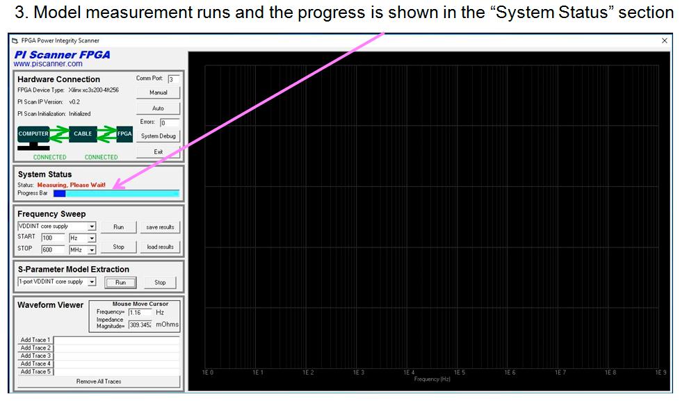
12 5. PI Scanner Application Screen The PI Scanner application screen contains five control panels and a waveform viewer window. The five control panels are: Hardware Connection, System Status, Frequency Sweep, S- Parameter Model Extraction, and Waveform Viewer. The following sections describe each of these panels Hardware Connection Panel The following figure shows the elements of the hardware connection panel. The hardware connection panel displays the FPGA device type, PI Scanner IP version configured in the FPGA device, and the status of the hardware connection and initialization. The COMM port of the USB to serial adapter board is also displayed. The Manual and Auto buttons are used for troubleshooting the serial interface connection. The Errors box shows if any serial communication error has occurred during measurement run time. The System Debug button is used for advanced troubleshooting mode System Status Panel The system status panel shows the measurement status and a progress bar. During measurement the status changes to Measurement, Please Wait! and the progress bar advances gradually until the measurement completes. 12


13 5.3. Frequency Sweep Panel The frequency sweep panel is shown in the figure below. The PI Scanner application can measure the impedance of various power domains of the FPGA power distribution network and the noise coupling between different power domains. The selection of power domain and coupling between domains is done using the selection tab highlighted in the picture below: In this PI Scanner configuration example there are two power domains, VDDINT for the 1.2V core supply of the Xilinx Spartan 3 FPGA and VDDO for the 3.3V I/Os supply. The user can select to measure the impedance of the VDDINT power supply domain, the impedance of the VDDO I/O power supply domain, the coupling from VDDO into VDDINT, or the coupling from VDDINT into VDDO. Different PI Scanner configurations for other types of FPGAs may contain additional power domains and coupling among power domains. The start and stop frequencies of the frequency sweep are selected using the START and STOP fields in the panel, as highlighted in the picture below. 13


14 The save results and load results buttons are used to store the measured waveforms and load previous measurements S-Parameter Model Extraction The S-Parameter Model Extraction panel includes a selection tab for power domain, a Run button that starts the s-parameter model extraction and a Stop button that can cancel the extraction process. This example configuration of PI Scanner, for Spartan 3 FPGA, has three options of s-parameter model extraction, as shown in the figure below. The three options are: 1-port VDDINT core supply s-parameter model, 1-port VDDO I/O power domain s-parameter model, and 2-port VDDINT and VDDO power domains Waveform Viewer Panel The waveform viewer panel controls what is displayed in the waveform viewer window and performs mouse-move cursor measurements of frequency and magnitude on the displayed trace. The waveform viewer panel enables the display of up to five traces previously stored in the memory. Each of the Add Trace X button includes a text field that displays the file name and folder where the corresponding trace is stored, as shown in the figure below: 14


15 The colors correspond to the colors of the waveforms displayed in the waveform viewer window, as shown in the picture below: 15
16 6. Example Measurement 1 PDN Impedance Frequency Sweep 16

17 17

18 18

19 7. Example Measurement 2 Extract S-Parameter Model of FPGA Core Supply PDN 19
20 20
21 8. Troubleshooting Support 1. If there is an issue with the serial link when starting PI Scanner application, the PI Scanner will wait around seconds before the application displays on the screen. This is because the software program scans all the available COM ports on the computer trying to communicate with the FPGA, as it does not know to which COM port the USB to serial adapter is connected. After searching all COM ports the PI Scanner application starts and displays the connection status as Not Connected in the hardware connection panel. 2. If the serial communication is not successful, exit PI Scanner application and check the cable connections between computer and the USB to serial adapter board and between the adapter board and FPGA. If the connections look correct, disconnect the power from the FPGA board and reconnect it back. After 1-2 seconds press/release momentarily the Reset button of the FPGA board, and restart PI Scanner. This is a common fix for serial link connections problems. If these methods do not fix the problem, contact us using the contact information on website. 21
1) Installing Bluetooth software for Windows (A) Place installation CD into PC and setup should launch automatically.
 Installing Bluetooth software for Windows (A) Place installation CD into PC and setup should launch automatically.") 1) Installing Bluetooth software for Windows (A) Place installation CD into PC and setup should launch automatically. If setup does not launch, use Windows Explorer to navigate to the appropriate CD- ROM
1) Installing Bluetooth software for Windows (A) Place installation CD into PC and setup should launch automatically. If setup does not launch, use Windows Explorer to navigate to the appropriate CD- ROM
A3-TFFCBL-02 USB-to-UART Adapter User Manual
 A3-TFFCBL-02 USB-to-UART Adapter User Manual Introduction The A3-TFFCBL-02 provides a convenient method for adapting UART data to USB signaling; it provides the following features: Converts from USB to
LOADING DRIVERS FOR SKYVIEW 2.0 XBEE INTERFACE USB DEVICE ON WINDOWS 8
 LOADING DRIVERS FOR SKYVIEW 2.0 XBEE INTERFACE USB DEVICE ON WINDOWS 8 After you have loaded the Skyview 2.0 software, with the xbee interface plugged in to your USB drive, you try to start the program
IDWedgeBT USB Virtual Serial Port Cable Installation, Configuration and Operation
 IDWedgeBT USB Virtual Serial Port Cable Installation, Configuration and Operation Introduction This document explains how to install, configure and use the IDWedgeBT USB Virtual Serial Port Cable to update
CommLink IV Technical Guide
 www.wattmaster.com CommLink IV Technical Guide Table of Contents General Information... 3 CommLink IV Overview...3 Optional IP Module Kit...3 Optional Remote Link II...3 Installing CommLink IV ONLY...3
PSIM Tutorial. How to Use SCI for Real-Time Monitoring in F2833x Target. February Powersim Inc.
 PSIM Tutorial How to Use SCI for Real-Time Monitoring in F2833x Target February 2013-1 - With the SimCoder Module and the F2833x Hardware Target, PSIM can generate ready-to-run codes for DSP boards that
USB-Link 2 Technical Guide
 www.wattmaster.com USB-Link 2 USB-Link 2 Code: SS0073 Version 4.11 and up Table of Contents General Information... 3 USB-Link 2 Overview...3 System Requirements...3 Quick Guide... 4 USB-Link 2 Driver Installation
AlphaBeam. Description. Requirements. for PC
 AlphaBeam for PC Description AlphaBeam is a software application you install on your computer that lets you beam text from your IR-capable AlphaSmart device to an IR-capable computer. AlphaBeam sends text
INTRODUCTION 2 FEATURES. 2 SPECIFICATIONS. 2 PIN ASSIGNMENT 2 DB-9 DB-25 CONVERSION TABLE. 2 DRIVER INSTALLATION QUICK GUIDE.. 2
 USB to RS-232 Converter Part Number: USB-232-1 Communications made easy CONTENTS INTRODUCTION 2 FEATURES. 2 SPECIFICATIONS. 2 PIN ASSIGNMENT 2 DB-9 DB-25 CONVERSION TABLE. 2 DRIVER INSTALLATION QUICK GUIDE..
1. Introduction. 2. Installation INSTALLATION INSTRUCTIONS: MCD USB MODULE
 Introduction INSTALLATION INSTRUCTIONS: MCD USB MODULE 1. Introduction The USB Module can be used in conjunction with WinMaster to manage Danfoss soft starters. These instructions detail the installation,
USB-Link Technical Guide
 www.wattmaster.com USB-Link Technical Guide USB-Link Code: SS0070 Table of Contents General Information... 3 USB-Link Overview...3 System Requirements...3 Quick Guide... 4 Connection and Wiring... 5 USB-Link
USB485. USB to RS485 Converter Card. User Manual for connecting with Windows Vista Version 1.01
 USB485 USB to RS485 Converter Card User Manual for connecting with Windows Vista Version 1.01 RMS Technologies 2533 N. Carson St. #4698, Carson City, NV 89706-0147 1-877- 301-3609 www.rmsmotion.com sales@rmsmotion.com
RS-422/485 PCIe Card
 RS-422/485 PCIe Card User Manual Ver. 3.00 All brand names and trademarks are properties of their respective owners. Contents: Chapter 1: Introduction... 3 1.1 Product Introduction... 3 1.2 Features...
RS-422/485 PCI Card User Manual Ver All brand names and trademarks are properties of their respective owners.
 RS-422/485 PCI Card User Manual Ver. 2.00 All brand names and trademarks are properties of their respective owners. Contents: Chapter 1: Introduction... 3 1.1 Product Introduction... 3 1.2 Features...
INSTALLING THE PS3 XBOX READY SOFTWARE:
 INSTALLING THE PS3 XBOX READY SOFTWARE: 1. Insert the Installation CD to CD-ROM drive and execute Ready_Setup.exe NOTE: If it is the first time for the target USB disk using under this software, the software
USB to RS-232/RS422/485. US-101-I USB To Serial Operation Manual
 USB to RS-232/RS422/485 US-101-I USB To Serial Operation Manual First Edition, Jun 2008 Table of Contents 1. Introduction 2 2. Package checklist 3 3. Product Specification 4 4. Product Panel Views Description
3.1 I-7560 Pin Assignment and Specifications: Introduction
 3.1 I-7560 Pin Assignment and Specifications: Introduction The I-7560 adds a Windows serial Com port via its USB connection and is compatible with new & legacy RS-232 devices. USB Plug and Play allows
SAKURA-W. Side-channel AttacK User Reference Architecture SAKURA-W Quick Start Guide. [Version 0.9] October 19, 2014.
![SAKURA-W. Side-channel AttacK User Reference Architecture SAKURA-W Quick Start Guide. [Version 0.9] October 19, 2014.](/thumbs/77/76644229.jpg "SAKURA-W. Side-channel AttacK User Reference Architecture SAKURA-W Quick Start Guide. [Version 0.9] October 19, 2014.") Side-channel AttacK User Reference Architecture SAKURA-W Quick Start Guide [Version 0.9] SAKURA-W October 19, 2014 Satoh Laboratory, The University of Electro Communications Revision Record Date Version
Side-channel AttacK User Reference Architecture SAKURA-W Quick Start Guide [Version 0.9] SAKURA-W October 19, 2014 Satoh Laboratory, The University of Electro Communications Revision Record Date Version
USB-Link 2 Technical Guide. USB-Link 2 Code: SS0073 Version 4.11 and up
 USB-Link 2 Technical Guide USB-Link 2 Code: SS0073 Version 4.11 and up TABLE OF CONTENTS Zone Zone General Information... 3 USB-Link 2 Overview...3 System Requirements...3 Quick Guide... 4 USB-Link 2 Driver
USB RS485/RS422 Converter INTRODUCTION USB-i485 USB-i485 SPECIFICATIONS USB-i485 USB-i485 NOVUS AUTOMATION 1/8
 NOVUS AUTOMATION 1/8 USB DRIVER INSTALLATION USB-i485 The following installation steps may be slightly different depending on your PC configuration and Windows version. Follow the Wizard instructions and
Note that FLIP is an Atmel program supplied by Crossware with Atmel s permission.
 INTRODUCTION This manual will guide you through the first steps of getting the SE-8051ICD running with the Crossware 8051 Development Suite and the Atmel Flexible In-System Programming system (FLIP). The
Shadow Custom Software. Scan-N-Send USERS Guide
 Shadow Custom Software Scan-N-Send USERS Guide Revision Date: 4/1/2008 Table of Content About Scan-N-Send Page 3 Software Application Installation Page 4-7 Scanner Driver Installation Page 7-11 Scanner
Windows 8 / 7 CONTENTS. USB to RS-422 Converter. Part Number: USB FEATURES. 2 SPECIFICATIONS. 2 CONNECTIONS.. 3
 CONTENTS USB to RS-422 Converter Part Number: USB-422-1 INTRODUCTION 2 FEATURES. 2 SPECIFICATIONS. 2 PIN ASSIGNMENT 2 CONNECTIONS.. 3 DRIVER INSTALLATION QUICK GUIDE.. 3 DRIVER INSTALLATION EXAMPLES..
DFS/Cutter. Debugging Communication Problems
 DFS/Cutter Technical Support Bulletin Debugging Communication Problems Abstract: This TSB is written to help users debug communication problems where the cutter appears to ignore everything the computer
Windows 8 / 7 CONTENTS. USB to RS-485 Converter. Part Number: USB FEATURES. 2 SPECIFICATIONS. 2 CONNECTIONS.. 3
 CONTENTS USB to RS-485 Converter Part Number: USB-485-1 INTRODUCTION 2 FEATURES. 2 SPECIFICATIONS. 2 PIN ASSIGNMENT 2 CONNECTIONS.. 3 DRIVER INSTALLATION QUICK GUIDE.. 3 DRIVER INSTALLATION EXAMPLES..
FSA-CU Configuration Utility Programming Guide
 FSA-CU Configuration Utility Programming Guide Revision 3 October 2013 Introduction The following guide will show you the basics of the FSA-CU configuration utility program. The CU can be used with the
USB-COMi-TB USB to Industrial Single RS-422 / 485 Adapter Manual. Specifications and Features
 USB-COMi-TB USB to Industrial Single RS-422 / 485 Adapter Manual The USB-COMi-TB USB-to-Industrial Single RS-422/485 Adapter is designed to make industrial communication port expansion quick and simple.
The USB-to-Serial Converter
 The USB-to-Serial Converter Older type with Prolific chipset Current type with FTDI chipset Introduction The USB Serial Converter attaches to a PC USB port and provides a serial port connector, to which
Revision History Revision Date Version Pages Description
 Revision History Revision Date Version Pages Description 2006-07-14 2.0 All Initial Release by shlee 2007-08-02 2.1 Partial Vista x32 added khheo 2008-05-13 2.2 Partial Multi-1 & Win2008 added by hjnoh
 / off / off 3. Press the Power button on the back of the base to power on the lamp; hold on the power button in the middle of the navigation buttons to power on the digital photo frame. 1. Press Exit
USB232 board EB Technical datasheet
 USB232 board EB039-00-1 Technical datasheet Contents 1. About this document...2 2. General information...3 3. Board layout...4 4. Testing this product...5 5. Circuit description...7 Appendix 1 Circuit
Version 2.4
 2009.10.26 Version 2.4 Revision History Revision Date Version Pages Description 2006-07-14 2.0 All Initial Release by shlee 2007-08-02 2.1 Partial Vista x32 added khheo 2008-05-13 2.2 Partial Multi-1 &
USB-Link 2 Technical Guide
 www.wattmaster.com USB-Link 2 Technical Guide USB-Link 2 Code: SS0073 Version 4.11 and up TABLE OF CONTENTS GENERAL INFORMATION... 3 USB-Link 2 Overview... 3 System Requirements... 3 QUICK GUIDE...4 USB-LINK
User s Guide. Ethernet Module for Barcode Printer
 User s Guide Ethernet Module for Barcode Printer 1. ETHERNET MODULE... 2 1-1. Functions... 2 1-2. General Specifications... 2 2. ETHERNET MODULE INSTALLATION... 3 2-1. Ethernet Module Installation for
Call System. User s Manual
 Call System User s Manual User s Manual 13 September 2011 HNS ANDON Call System Copyright 2011 HNS Technical Development Ltd. H-9027 Győr, Gesztenyefa 4. www.hns.eu/spce Phone.: +36 (96) 506-930 Fax: +36
Serial Adaptor Isolated USB to TTL Device Driver - Installation Guide 1 Introduction. 2 Installing the Device Driver Software (Windows XP )
") Serial Adaptor Isolated USB to TTL Device Driver - Installation Guide 1 Introduction This installation guide describes a simple, step-by-step procedure to enable the supplied Serial Adapter to work using
Serial Adaptor Isolated USB to TTL Device Driver - Installation Guide 1 Introduction This installation guide describes a simple, step-by-step procedure to enable the supplied Serial Adapter to work using
Commercial Grade USB to RS-422/485 Adapter User's Manual
 Commercial Grade USB to RS-422/485 Adapter User's Manual Table of Contents Safety Instructions...3 Introduction...4 Features...4 Package Contents...5 System Requirement...5 Product Overview...6 Pin Assignment...8
USB-Link 2 Technical Guide. USB-Link 2 Code: SS0073 Version 4.11 and up
 USB-Link 2 Technical Guide USB-Link 2 Code: SS0073 Version 4.11 and up TABLE OF CONTENTS GENERAL INFORMATION... 3 USB-Link 2 Overview... 3 System Requirements... 3 QUICK GUIDE...4 USB-LINK 2 DRIVER INSTALLATION
User Guide Feb 5, 2013
 HI 8435 32 Sensor Array with Ground/Open or Supply/Open Sensors and SPI interface. Evaluation Board 23351 Madero, Mission Viejo, CA 92691. USA. Tel: + 1 949 859 8800 Fax: + 1 949 859 9643 Email: sales@holtic.com
Trouble shooting the DeskCNC controller:
 Checking for a functional card. 1) Unplug/Disconnect all connections to the I/O and step and direction pins/terminals. 2) Apply regulated 5vdc to the +5 and gnd terminals. CHECK FOR CORRECT POLARITY WITH
Firmware, Database, & PC Application Update Installation Instructions
 Firmware, Database, & PC Application Update Installation Instructions IMPORTANT Please read before you begin the installation. To avoid possible errors, it is recommended to install the updates as described
Saab TransponderTech. R4 Display SW Update Instruction
 Saab TransponderTech R4 Display SW Update Instruction i COPYRIGHT The entire contents of this instruction and its appendices, including any future updates and modifications, shall remain the property of
D8000 SERIES QUICK START GUIDE
 D8000 SERIES QUICK START GUIDE Version 1.0 Overview The D8000 series modules require a DC Voltage power supply, a USB cable and an unused computer USB port for proper operation. Connecting the D8000 series
keyestudio Keyestudio MEGA 2560 R3 Board
 Keyestudio MEGA 2560 R3 Board Introduction: Keyestudio Mega 2560 R3 is a microcontroller board based on the ATMEGA2560-16AU, fully compatible with ARDUINO MEGA 2560 REV3. It has 54 digital input/output
EMUL-PPC-PC. Getting Started Guide. Version 1.0
 EMUL-PPC-PC Getting Started Guide Version 1.0 EMUL PowerPC Getting Started Guide Edition1 ICE Technology. All rights reserved worldwide. Contents Warranty Information European CE Requirements User Responsibility
User Manual. LPC-StickView V1.1. for LPC-Stick. Contents
 User Manual LPC-StickView V1.1 for LPC-Stick Contents 1 What is LPC-Stick? 2 2 System Components 2 3 Installation 2 4 Updates 3 5 Starting the LPC-Stick View Software 4 6 Operating the LPC-Stick 6 7 Start
This 4-port RS-422/485 Adapter is provided with an external switching power adapter in the package.
 USB-4COMi-M USB to Quad RS-422/485 to Serial Adapter Manual The USB to Industrial Quad RS-422/485 Adapter is designed to make industrial communication port expansion quick and simple. Connecting to a USB
Instructions for Installing FlashUpdate and Downloading Updates for NPRT 2200 Noise Power Ratio Test Set
 Instructions for Installing FlashUpdate and Downloading Updates for NPRT 2200 Noise Power Ratio Test Set Updates to the instrument firmware are available from the Applied Instruments website. Requirements
EXPRESS. Users Guide. Version 3.5
 EXPRESS Users Guide Version 3.5 Table of Contents 1 System Overview... 3 2 System Requirements... 3 3 Contents in ECMTUNE System Box... 3 4 Installation Information... 4 5 Registration Information... 7
SCA8X0-21X Demo Kit User Manual. Doc.Nr C
 SCA8X0-21X0-3100 Demo Kit TABLE OF CONTENTS SCA8X0-21X0-31X0 DEMO KIT 1 Introduction...3 2 Quick start for using the SCA8X0-21X0-31X0 DEMO KIT...3 3 Hardware...4 4 GUI software...4 4.1 Resetting GUI and
USB UART 4 click PID: MIKROE Weight: 23 g
 USB UART 4 click PID: MIKROE-2810 Weight: 23 g USB UART 4 click features well-known FT232RL USB-to-UART interface module from FDTI. It provides USB to asynchronous serial data transfer interface, allowing
Instructions for Installing FlashUpdate and Downloading Updates for Super Buddy Satellite Meter
 Instructions for Installing FlashUpdate and Downloading Updates for Super Buddy Satellite Meter Updates to the Field Guide and to the instrument firmware are available from the Applied Instruments website.
VS-626M5 Parameter Upload/Download Software User s Manual (Preliminary) 5/18/99
 5/18/99") VS-626M5 Parameter Upload/Download Software User s Manual (Preliminary) 5/18/99 Computer Requirements The following hardware and software are required to run the M5 Parameter Upload/Download software.
VS-626M5 Parameter Upload/Download Software User s Manual (Preliminary) 5/18/99 Computer Requirements The following hardware and software are required to run the M5 Parameter Upload/Download software.
Using your Brady Printer connected to your PC.
 Using your Brady Printer connected to your PC. While the IDXPERT Thermal Labeling System is sold as a standalone printer, it can also be used connected to your PC using optional Labelmark Software. This
INTRODUCTION...1. Under Windows 98SE... 2 Under Windows ME... 6 Under Windows Under Windows XP...10
 CONTENTS INTRODUCTION...1 I. Install the USB-IrDA Adaptor driver... 2 Under Windows 98SE... 2 Under Windows ME... 6 Under Windows 2000... 9 Under Windows XP...10 II. Make sure the USB-IrDA Adaptor installed
User Manual. LPC-StickView V3.0. for LPC-Stick (LPC2468) LPC2478-Stick LPC3250-Stick. Contents
 LPC2478-Stick LPC3250-Stick. Contents") User Manual LPC-StickView V3.0 for LPC-Stick (LPC2468) LPC2478-Stick LPC3250-Stick Contents 1 What is the LPC-Stick? 2 2 System Components 2 3 Installation 3 4 Updates 3 5 Starting the LPC-Stick View Software
User Manual LPC-StickView V3.0 for LPC-Stick (LPC2468) LPC2478-Stick LPC3250-Stick Contents 1 What is the LPC-Stick? 2 2 System Components 2 3 Installation 3 4 Updates 3 5 Starting the LPC-Stick View Software
UM2119 User manual. Graphical user interface (GUI) for EVAL-L9907-H. Introduction
 for EVAL-L9907-H. Introduction") User manual Graphical user interface (GUI) for EVAL-L9907-H Introduction This document describes the STSW-L9907 the Graphical User Interface (GUI) dedicated to set and control the EVAL-L9907-H board (3-phase
User manual Graphical user interface (GUI) for EVAL-L9907-H Introduction This document describes the STSW-L9907 the Graphical User Interface (GUI) dedicated to set and control the EVAL-L9907-H board (3-phase
Fremont (MAXREFDES6#) Nexys 3 Quick Start Guide
 Nexys 3 Quick Start Guide") Fremont (MAXREFDES6#) Nexys 3 Quick Start Guide Rev 0; 9/13 Maxim Integrated cannot assume responsibility for use of any circuitry other than circuitry entirely embodied in a Maxim Integrated product.
Fremont (MAXREFDES6#) Nexys 3 Quick Start Guide Rev 0; 9/13 Maxim Integrated cannot assume responsibility for use of any circuitry other than circuitry entirely embodied in a Maxim Integrated product.
USB-16COMi-M 16-Port RS-422/485 USB Serial Adapter User Manual. Features and Specifications. Power Supply
 USB-16COMi-M 16-Port RS-422/485 USB Serial Adapter User Manual The USB to industrial 16-Port RS-422/485 Adapter is designed to make serial port expansion quick and simple. Connecting to a USB port on your
MMI6070 Quick Start Guide
 MMI6070 Quick Start Guide Introduction If at any time more information is required on HMI safety and protection ratings, HMI Power, and HMI communication, please refer to the MMI6070 Installation Guide
VSM Manager. The VSM Manager is a Windows GUI that can be installed to serially control Genesis Matrixes with a firmware of version 2.5 or later.
 VSM Manager Table of Contents Overview...1 Getting Started...1 Toolbar... 2 Serial Connection... 2 Refresh... 3 Help... 3 Tab Pages... 4 General... 4 Control...5 Schedule... 6 Command... 6 Communications...
USB to RS-422/485 Serial Adapter
 USB to RS-422/485 Serial Adapter User Manual Ver. 4.00 All brand names and trademarks are properties of their respective owners. Contents: Chapter 1: Introduction... 3 1.1 Product Introduction... 3 1.2
1. Main Features. TCIC User s Manual
 1. Main Features 2. Installation 3. TCIC-Monitor 3.1 Title 3.2 Menus 3.2.1 File 3.2.1.1 Exit 3.2.2 Setup 3.2.2.1 Card Settings 3.2.2.2 TCIC-Monitor Settings 3.2.2.3 Calibration and Defaults 3.2.2.4 Card
PCI Express 16-Port Serial I/O Cards
 PCI Express 16-Port Serial I/O Cards The PCIe-1600 PCI Express 16-port serial I/O card is a plug & play high-speed serial I/O expansion card for PCI Express bus. Connecting to a PCI Express bus on your
DP Color LCD Digital Photo Key Chain QUICK SETUP GUIDE
 DP161 1.5 Color LCD Digital Photo Key Chain QUICK SETUP GUIDE Getting Started- VERSION DPKEY and 161SX STEP-1-INSTALL The Photo Viewer Software Install the Photo Viewer Software to transfer images to the
Quick Start Guide for the Turbo upsd DK3300-ELCD Development Kit- RIDE
 Contents: Circuit Board upsd DK3300-ELCD Development Board with a upsd3334d-40u6 MCU with Enhanced Graphic LCD RLINK-ST, a USB-based JTAG adapter from Raisonance for debugging with Raisonance Integrate
ELAD FDM-DUO User Manual - Rev /2016
 8 Firmware update This section describes how to update the various firmware of the FDM-DUO. The latest firmware versions are available here: http://sdr.eladit.com/fdm-duo/firmware Releases/. TO FACILITATE
SECTION 3 NV9 USB MANUAL SET
 SECTION 3 NV9 USB MANUAL SET ITL SOFTWARE SUPPORT GUIDE NV9 USB Manual Set Section 3 2 NV9 USB MANUAL SET SECTION 3 3. ITL SOFTWARE SUPPORT GUIDE 3 3.1 Validator Manager Software 3 3.1.1 Preparing for
Connecting a CNC to a PC wireless over WiFi
 Connecting a CNC to a PC wireless over WiFi This guide describes how to wireless connect a CNC machine to a PC using WiFi, thereby being able to send programs from the PC to the CNC machine. The Setup
Exchequer Integration
 Exchequer Integration Client Installation Document Version 1.4 V1 Exchequer Client Installation 1 Contents Exchequer V1 Integration Client Installation... 3 Client Workstations... 4 Assumptions:... 5 Instructions
Industrially Isolated USB to Serial Adapter User s Manual
 Industrially Isolated USB to Serial Adapter User s Manual UTS-31TBi / UTS-31DBi / UTS-231DBi UTS-431DBi / UTS-1231DB Table of Contents 1. Introduction...1 Features...1 Specification:...2 2. Windows OS
Troubleshooting. Note. SC485, USB485 and USB485B. Table of Contents.
 SC485, USB485 and USB485B Troubleshooting Note www.lightorama.com Use this document if: 1. You want to locate the Windows communications port name being used by the RS485 adapter. 2. You believe the USB
96Boards UART Adapter User Guide
 96Boards UART Adapter User Guide For versions v1.0 and v1.1 of the UART adapter board Introduction This is the user guide for the 96Boards UART adapter board. The board provides a USB to UART adapter to
Campbell (MAXREFDES4#) Nexys 3 Quick Start Guide
 Nexys 3 Quick Start Guide") Campbell (MAXREFDES4#) Nexys 3 Quick Start Guide Pmod Connector Alignment Required Equipment Windows PC with Xilinx ISE /SDK version 13.4 or later and two USB ports License for Xilinx EDK/SDK version 13.4
Campbell (MAXREFDES4#) Nexys 3 Quick Start Guide Pmod Connector Alignment Required Equipment Windows PC with Xilinx ISE /SDK version 13.4 or later and two USB ports License for Xilinx EDK/SDK version 13.4
This procedure is for updating (or reverting) Software and Firmware on the Videosys Broadcast camera control system.
 Software and Firmware on the Videosys Broadcast camera control system.") Software and Firmware Update Guide Notes: This procedure is for updating (or reverting) Software and Firmware on the Videosys Broadcast camera control system. The process is designed to be run on Windows
Software and Firmware Update Guide Notes: This procedure is for updating (or reverting) Software and Firmware on the Videosys Broadcast camera control system. The process is designed to be run on Windows
Windows NT Server Printer Driver Upgrade Instructions
 Windows NT Server Printer Driver Upgrade Instructions The steps detailed below describe the most reliable method to upgrade printer driver versions after v1.6.0227a on a Windows NT 4.0 Server that is shared
RPLIDAR A2. Development Kit User Manual. Low Cost 360 Degree Laser Range Scanner. Model: A2M4. Shanghai Slamtec.Co.,Ltd rev.1.
 2016-10-28 rev.1.1 RPLIDAR A2 Low Cost 360 Degree Laser Range Scanner Development Kit User Manual Model: A2M4 www.slamtec.com Shanghai Slamtec.Co.,Ltd Contents CONTENTS... 1 OVERVIEW... 3 ITEMS IN THE
Document Name: User Manual for SC10EK4 Serial to Ethernet Converter with 4 TCP Sockets. Index
 Document Name: User Manual for SC10EK4 Serial to Ethernet Converter with 4 TCP Sockets. Index Technical Specifications 1 Installation Procedure 1 LED Indications 2 Configuration Procedure Configuration
Plug the USB cable into the WebMaster/WebAlert and your computer. You will see this message on your screen
 QUICK START GUIDE USB DRIVER INSTALLATION Step 1 Plug the USB cable into the WebMaster/WebAlert and your computer. You will see this message on your screen Step 2 Go to Start, Control Panel and Click System
67 Series Spectrophotometer PC Software
 67 Series Spectrophotometer PC Software Instruction Manual 670 004/Rev D/04-17 IMPORTANT Please ensure the SD Card is fitted into the socket as detailed in the image below. -------------------------------------------------------------------------------------------------------------------------
SIMPlugIN-Programmer Utility User Manual.
 file: simplugin_programmer_utility_user_manual_en_rev_01.odm page. 1 / 9 SIMPlugIN-Programmer Utility User Manual. 1 Revision History. Revision Description 0.1 First Release. file: simplugin_programmer_utility_user_manual_en_rev_01.odm
FURIOUS TRUE-D DIVERSITY RECEIVER V3.6 Attitude
 FURIOUS TRUE-D DIVERSITY RECEIVER V3.6 Attitude USER S MANUAL Please contact us if you need further assistance: Tech support: tech@furiousfpv.com Sales support: sales@furiousfpv.com Website: http://furiousfpv.com/
AutoDome Modular Camera System
 AutoDome Modular Camera System VG4 Series Firmware Update Manual en User s Manual AutoDome Modular Camera System Table of Contents en iii Table of Contents 1 VG4 Firmware Update via a TCP/IP Network 1
TABLE OF CONTENTS COPYRIGHT INTRODUCTION...3 PRODUCT OVERVIEW...3 COMPONENTS AND FEATURES...3 HARDWARE INSTALLATION
 TABLE OF CONTENTS COPYRIGHT...2 1. INTRODUCTION...3 PRODUCT OVERVIEW...3 COMPONENTS AND FEATURES...3 HARDWARE INSTALLATION...3 2. MFP SERVER INSTALLATION...5 PREPARATION...5 CONFIGURATION SOLUTION TABLE...5
PROFESSIONAL. Users Guide. Version 3.5
 PROFESSIONAL Users Guide Version 3.5 Table of Contents 1 System Overview... 3 2 System Requirements... 3 3 Contents in ECMTUNE System Box... 3 4 Installation Information... 4 5 Registration Information...
Lumitester PD-30. Control Software. Instruction Manual. Table of Contents
 Table of Contents Lumitester PD-30 Control Software Instruction Manual Thank you very much for purchasing the Lumitester PD-30. All of this Instruction Manual must be read before operation of this product
Reno A & E, 4655 Aircenter Circle, Reno, NV (775) Release Date: February 5, 2008 All Reno A&E monitors. All versions of RaeComM.
 Release Date: February 5, 2008 All Reno A&E monitors. All versions of RaeComM.") Product: RaeComM Title: RaeComM Basics Release Date: February 5, 2008 Scope: All Reno A&E monitors. All versions of RaeComM. Installing RaeComM The most current version of RaeComM software is available
Product: RaeComM Title: RaeComM Basics Release Date: February 5, 2008 Scope: All Reno A&E monitors. All versions of RaeComM. Installing RaeComM The most current version of RaeComM software is available
LM058 Bluetooth Serial Adapter
 LM058 Bluetooth Serial Adapter with external antenna The LM058 Bluetooth Serial Adapter eliminates your conventional RS232 serial cables, providing an easy-to-use, invisible connection with freedom of
USER GUIDE. K-Router Plus Online User Guide. Version P/N: Rev 1
 KRAMER ELECTRONICS LTD. USER GUIDE K-Router Plus Online User Guide Version 2.0.28 P/N: 2900-300247 Rev 1 Contents 1 Introduction 1 2 Downloading and Installing K-Router Plus 2 3 Defining K-Router Plus
MultiPort USB User Manual
 MultiPort USB User Manual Version 2.8 2011. 07. 16 Revision History Revision Date Version Pages Description 2006-07-14 2.0 All Initial Release by shlee 2007-08-02 2.1 Partial Vista x32 added khheo 2008-05-13
Longshine Technologie Europe GmbH
 Longshine Technologie Europe GmbH www.longshine.de TABLE OF CONTENTS COPYRIGHT...2 1. INTRODUCTION...3 PRODUCT OVERVIEW...3 COMPONENTS AND FEATURES...3 HARDWARE INSTALLATION...3 2. MFP SERVER INSTALLATION...5
DIRECT LINK FLASH TUNER
 DIRECT LINK FLASH TUNER Quick Start Guide This Guide is intended to answer basic Direct Link tuning questions and to act as a Quick Start Guide. It is not intended to be encyclopedic on the tuning process
DriveWizard Plus Instruction Manual
 DriveWizard Plus Instruction Manual To properly use the product, read this manual thoroughly. MANUAL NO. TOEP C730600 20C Table of Contents Safety Symbols and Markings...4 Manual Overview...5 Related Manuals...5
Innovati s Bluetooth 100M Universal Wireless Bluetooth Module
 Innovati s Bluetooth 100M Universal Wireless Bluetooth Module Bluetooth 100M module is a simple to use Bluetooth module, command control through a simple UART Tx and Rx which are connected to other Bluetooth
Firmware, Database, & PC Application Update Installation Instructions
 Firmware, Database, & PC Application Update Installation Instructions IMPORTANT Please read before you begin the installation. To avoid possible errors, it is recommended to install the updates as described
PROGRAMMING INSTRUCTIONS
 HOERBIGER Engine Solutions PROGRAMMING INSTRUCTIONS CPU-XL VARISPARK TERMINAL PROGRAM WARNING: WARNING: DEVIATION DEVIATION FROM THESE FROM INSTRUCTIONS THESE INSTRUCTIONS MAY LEAD MAY LEAD TO IMPROPER
XC2287 HOT. Exercise CAN_1 Communication using the CAN Module
 XC2287 HOT Exercise CAN_ Communication using the CAN Module XC2267 HOT Exercise CAN_ Serial Communication using the CAN Let s get started now! Page 2 HOT Exercise CAN_ Simple USIC Example In this exercise
Addendum to Active Breathing Coordinator R3.0 Installation and Service. Installation Instructions for Windows 10
 Addendum to Active Breathing Coordinator R3.0 Installation and Service Installation Instructions for Windows 10 4-16-2019 Laptop software installation A1 Laptop software installation for Windows 10 Contents
Expected Configuration. Connecting the TL-One to the Digital Video Creator 80
 Overview This document describes how to transfer video clips from a TL-One Digital Video Recorder (DVR) to a Personal Computer (PC) using the Dazzle Digital Video Creator 80. The clips can then be written
OTC 3210 Update Instructions
 OTC 3210 Update Instructions Date of Release: June 2016 New Software ID: ACAC Previous Software ID: D4A8 or 6D2B Note: Scanning Suite should already be installed on the PC. Verify Scan Tool Software Version