TIDA V Stepper Motor Controller with Integrated Current Sense Reference Design
|
|
|
- Clare Ford
- 5 years ago
- Views:
Transcription


1 Test Report TIDA November 2015 TIDA V Stepper Motor Controller with Integrated Current Sense Reference Design Design Overview TIDA showcases the benefits of integrated current sensing for stepper motors. Integrated current sensing eliminates all current sense resistors while providing accurate current regulation. This feature is available in the. The EVM is used as the demonstration platform for this feature. Design Resources TIDA MSP430F2617 Design Folder Product Folder Product Folder Design Features 8.0- to 37-V Operating Supply Voltage Range with up to 1.5-A full-scale continuous motor current Integrated Current Sense Functionality o No Sense Resistors Required o +/- 6.25% Full-Scale Current Accuracy Simple GUI for driver input control and motor tuning Onboard USB communication for easy connectivity with external controller 100 mil header gives test probe access to all driver input controls Featured Applications Multi-Function Printers and Scanners Laser Beam Printers 3D Printers Automatic Teller and Money Handling Machines Video Security Cameras Office Automation Machines Factory Automation and Robotics TIDA November 2015 TID#
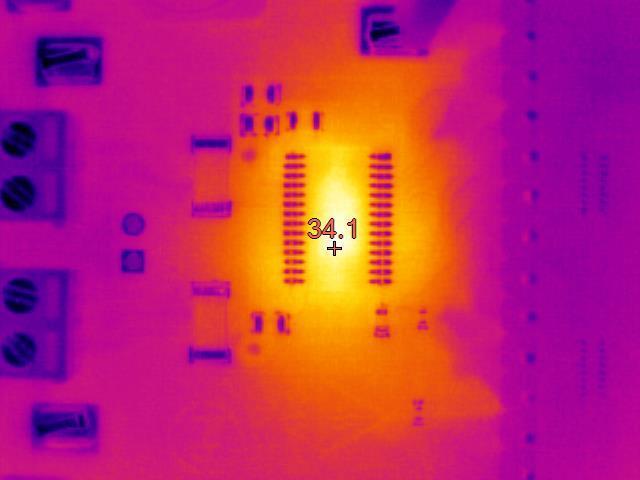
2 1. Introduction Traditional stepper motor drivers rely on external resistors to monitor the current through each winding. The current creates a voltage across the resistor that is monitored by an internal comparator. The comparator voltage reference is changed based on the desired current and location in the index table. Recently, some stepper motor drivers have integrated current regulation inside the device. One method is to integrate the current sense resistors into the package or by comparing the voltage across current sense FETs in parallel with the low-side drivers. Integrating the current sense resistors reduces the number of external components, but also causes the heat generated by the resistor to move inside the package. Another method is to use current sense FETs to monitor current instead of current sense resistors. This eliminates the cost of two external sense resistors and saves PCB area, which in turn helps with design layout and manufacturability. Assuming the internal RDS(ON) of the devices are the same, extra heat may also be reduced. In a constrained environment using multiple stepper motor drivers, this may reduce the need for additional heatsinking in the system. Using the motor driver, this design demonstrates the ability to regulate current with integrated current sense FETs. 2 Test Data 2.1 Current Comparison The and were chosen for this comparison because the two devices can be configured with the same decay and off times. The variables in the data are reduced to the current regulation method and the R DS(ON) differences between the two devices. Both the and are set to Mixed decay: 30% mode for both increasing and decreasing steps. Both the and are set to 20 µs PWM off time. The R DS(ON) (860 mω typical) is higher than the R DS(ON) (630 mω typical). This can account for the additional heat in the device. NOTE: The recommended decay setting for the is AutoTune. AutoTune was not used to allow comparison of current accuracy of the two methods. The AutoTune setting selects the decay mode for minimal current ripple across voltage and motor inductance variations. The following scope captures compares motor performance with internal current sensing versus the more traditional usage of external sense resistors. Three motors were used to regulate different current at different levels and motor inductances. 2 TID#00867 TIDA November 2015
3 MOTOR 1 System Voltage 24 Volts Current Setting 0.23 Amps Speed 300 1/4µsteps Motor 1 Specifications Manufacturer Portescap Model Number 42M048C2B Resistance per Phase +/- 10% 52.4 Ohms Inductance per Phase, typ 85.7 mh Rated Curent per Phase 0.23 Amps TIDA November 2015 TID#

4 4 TID#00867 TIDA November 2015
5 MOTOR 2 System Voltage 24 Volts Current Setting 1.0 Amps Speed 300 1/4µsteps Motor 2 Specifications Manufacturer Trinamic Model Number QSH Resistance per Phase at 20 C 4.5 Ohms Inductance per Phase, typ 7.5 mh Rated Curent per Phase 1.0 Amps TIDA November 2015 TID#

6 6 TID#00867 TIDA November 2015
7 MOTOR 3 System Voltage 24 Volts Current Setting 1.5 Amps Speed 300 1/4µsteps Motor 3 Specifications Manufacturer Trinamic Model Number QSH Resistance per Phase at 20 C 0.7 Ohms Inductance per Phase, typ 1.4 mh Rated Curent per Phase 1.5 Amps TIDA November 2015 TID#
8 8 TID#00867 TIDA November 2015


9 2.2 Additional Benefits Comparing the EVM with the EVM illustrates the component savings, and the potential PCB area savings when using integrated current sensing. It is important to note the lack of sense resistors on the EVM as compared to the EVM. The also has fewer pins than the allowing for a smaller package. 3D and 2D layout, respectively, of and for comparison. Dimensions are scaled for proper comparison X 650 mils X 790 mils Y 510 mils Y 590 mils Area sq mils Area sq mils Area sq inches Area sq inches TIDA November 2015 TID#
10 3. About the Author Rick Duncan is an Applications Engineer for Texas Instrument s motor drive business, where he is responsible for supporting TI s motor drive portfolio. Rick graduated from Louisiana State University with a Bachelor s of Science in Electrical Engineering. 10 TID#00867 TIDA November 2015
11 IMPORTANT NOTICE FOR TI REFERENCE DESIGNS Texas Instruments Incorporated ("TI") reference designs are solely intended to assist designers ( Buyers ) who are developing systems that incorporate TI semiconductor products (also referred to herein as components ). Buyer understands and agrees that Buyer remains responsible for using its independent analysis, evaluation and judgment in designing Buyer s systems and products. TI reference designs have been created using standard laboratory conditions and engineering practices. TI has not conducted any testing other than that specifically described in the published documentation for a particular reference design. TI may make corrections, enhancements, improvements and other changes to its reference designs. Buyers are authorized to use TI reference designs with the TI component(s) identified in each particular reference design and to modify the reference design in the development of their end products. HOWEVER, NO OTHER LICENSE, EXPRESS OR IMPLIED, BY ESTOPPEL OR OTHERWISE TO ANY OTHER TI INTELLECTUAL PROPERTY RIGHT, AND NO LICENSE TO ANY THIRD PARTY TECHNOLOGY OR INTELLECTUAL PROPERTY RIGHT, IS GRANTED HEREIN, including but not limited to any patent right, copyright, mask work right, or other intellectual property right relating to any combination, machine, or process in which TI components or services are used. Information published by TI regarding third-party products or services does not constitute a license to use such products or services, or a warranty or endorsement thereof. Use of such information may require a license from a third party under the patents or other intellectual property of the third party, or a license from TI under the patents or other intellectual property of TI. TI REFERENCE DESIGNS ARE PROVIDED "AS IS". TI MAKES NO WARRANTIES OR REPRESENTATIONS WITH REGARD TO THE REFERENCE DESIGNS OR USE OF THE REFERENCE DESIGNS, EXPRESS, IMPLIED OR STATUTORY, INCLUDING ACCURACY OR COMPLETENESS. TI DISCLAIMS ANY WARRANTY OF TITLE AND ANY IMPLIED WARRANTIES OF MERCHANTABILITY, FITNESS FOR A PARTICULAR PURPOSE, QUIET ENJOYMENT, QUIET POSSESSION, AND NON-INFRINGEMENT OF ANY THIRD PARTY INTELLECTUAL PROPERTY RIGHTS WITH REGARD TO TI REFERENCE DESIGNS OR USE THEREOF. TI SHALL NOT BE LIABLE FOR AND SHALL NOT DEFEND OR INDEMNIFY BUYERS AGAINST ANY THIRD PARTY INFRINGEMENT CLAIM THAT RELATES TO OR IS BASED ON A COMBINATION OF COMPONENTS PROVIDED IN A TI REFERENCE DESIGN. IN NO EVENT SHALL TI BE LIABLE FOR ANY ACTUAL, SPECIAL, INCIDENTAL, CONSEQUENTIAL OR INDIRECT DAMAGES, HOWEVER CAUSED, ON ANY THEORY OF LIABILITY AND WHETHER OR NOT TI HAS BEEN ADVISED OF THE POSSIBILITY OF SUCH DAMAGES, ARISING IN ANY WAY OUT OF TI REFERENCE DESIGNS OR BUYER S USE OF TI REFERENCE DESIGNS. TI reserves the right to make corrections, enhancements, improvements and other changes to its semiconductor products and services per JESD46, latest issue, and to discontinue any product or service per JESD48, latest issue. Buyers should obtain the latest relevant information before placing orders and should verify that such information is current and complete. All semiconductor products are sold subject to TI s terms and conditions of sale supplied at the time of order acknowledgment. TI warrants performance of its components to the specifications applicable at the time of sale, in accordance with the warranty in TI s terms and conditions of sale of semiconductor products. Testing and other quality control techniques for TI components are used to the extent TI deems necessary to support this warranty. Except where mandated by applicable law, testing of all parameters of each component is not necessarily performed. TI assumes no liability for applications assistance or the design of Buyers products. Buyers are responsible for their products and applications using TI components. To minimize the risks associated with Buyers products and applications, Buyers should provide adequate design and operating safeguards. Reproduction of significant portions of TI information in TI data books, data sheets or reference designs is permissible only if reproduction is without alteration and is accompanied by all associated warranties, conditions, limitations, and notices. TI is not responsible or liable for such altered documentation. Information of third parties may be subject to additional restrictions. Buyer acknowledges and agrees that it is solely responsible for compliance with all legal, regulatory and safety-related requirements concerning its products, and any use of TI components in its applications, notwithstanding any applications-related information or support that may be provided by TI. Buyer represents and agrees that it has all the necessary expertise to create and implement safeguards that anticipate dangerous failures, monitor failures and their consequences, lessen the likelihood of dangerous failures and take appropriate remedial actions. Buyer will fully indemnify TI and its representatives against any damages arising out of the use of any TI components in Buyer s safety-critical applications. In some cases, TI components may be promoted specifically to facilitate safety-related applications. With such components, TI s goal is to help enable customers to design and create their own end-product solutions that meet applicable functional safety standards and requirements. Nonetheless, such components are subject to these terms. No TI components are authorized for use in FDA Class III (or similar life-critical medical equipment) unless authorized officers of the parties have executed an agreement specifically governing such use. Only those TI components that TI has specifically designated as military grade or enhanced plastic are designed and intended for use in military/aerospace applications or environments. Buyer acknowledges and agrees that any military or aerospace use of TI components that have not been so designated is solely at Buyer's risk, and Buyer is solely responsible for compliance with all legal and regulatory requirements in connection with such use. TI has specifically designated certain components as meeting ISO/TS16949 requirements, mainly for automotive use. In any case of use of non-designated products, TI will not be responsible for any failure to meet ISO/TS16949.IMPORTANT NOTICE Mailing Address: Texas Instruments, Post Office Box , Dallas, Texas Copyright 2015, Texas Instruments Incorporated
The photograph below shows the PMP9730 Rev E prototype assembly. This circuit was built on a PMP9730 Rev D PCB.
 1 Photos The photograph below shows the PMP9730 Rev E prototype assembly. This circuit was built on a PMP9730 Rev D PCB. 2 Standby Power No Load Pin AC (W) 120VAC/60Hz 0.187 230VAC/50Hz 0.238 Page 1 of
TLK10081 EVM Quick Start Guide Texas Instruments Communications Interface Products
 TLK10081 EVM Quick Start Guide Texas Instruments Communications Interface Products 1 Board Overview +5 V Adapter Input Connector for voltage monitor board Connector for SMA break-out or FPGA board. Allows
1 Photo. 7/15/2014 PMP10283 Rev A Test Results
 1 Photo The photographs below show the PMP10283 Rev A assembly. This circuit was built on a PMP10283 Rev A PCB. Top side: Bottom side: Page 1 of 17 2 Efficiency 120V AC /60Hz Vin(ac) Iin(A) Pin(W) PF Vo1(V)
Test Report PMP Test Data For PMP /20/2015
 Test Data For PMP10748 09/20/2015 1 09/20/2015 Table of Contents 1. Design Specifications... 2 2. Circuit Description... 3 3. Block Diagram... 4 4. Board Schematic... 5 5. PMP10748 Board Photos... 6 6.
TIDA Test Report
 Test Report October 2015 TIDA-00623 Test Report Jing Zou BMS/WLPC Abstract TI design TIDA-00623 wireless power supply transmitter is an application of the bq50002 and bq500511 devices in a 5W Qi compliant
TIDA Test Report
 Test Report January 2015 TIDA-00334 Test Report Bill Johns BMS/WLPC Abstract TI design TIDA-00334 wireless power supply transmitter is an application of the bq500212a IC in a small form factor design targeted
The photographs below show the top and bottom view of the PMP11282Rev A board, which is built on PMP11064 Rev B PCB. Top Side
 1 Photo The photographs below show the top and bottom view of the PMP11282Rev A board, which is built on PMP11064 Rev B PCB. Top Side Bottom Side Page 1 of 22 2 Efficiency The efficiency curves of total
Single Cell Battery Power Solution
 Single Cell Battery Power Solution Input 5V DC Output 2.80.. 4.28V (dependent on charge state of battery) Current limited to 500mA max. Devices TPS2113A Autoswitching Power MUX TPD4S012 4-Channel USB ESD
Systems ATE report. All output measurements are taken with 1uF and a 0.1uF MLCC across the DUT output.
 Systems ATE report Substrate - Description PMP - BOM E deg ambient Test Notes CH = Vout CH = Vin AC CH = Iout Vout measurements taken with output cable All output measurements are taken with uf and a.uf
TIDA DS125BR820 40GbE/10GbE QSFP Reference Design User s Guide
 User s Guide May 2015 TIDA-00417 DS125BR820 40GbE/10GbE QSFP Reference Design User s Guide Version 2 May 2015 The information and/or drawings set forth in this document and all rights in and to inventions
PMP11140 TPS40400 / CSD85301Q2 Test Report 12V to 1.8V 3A / 4A Texas Instruments
 -Table of Contents: Comments & GUI settings page 1 Thermal images at 3A load w/o fan & at 4A load w/o & with fan page 2 Major switching waveform: Full load: 1 pulse and 10 cycles page 3 Ripple out at full
IndoTraq Development Kit 1: Command Reference
 IndoTraq Development Kit 1: Command Reference April 2016 Page 1 of 9 Copyright 2016, IndoTraq LLC DK1 Command Reference v1.0 Contents 1 Introduction... 3 1.1 Writing Conventions... 3 2 Basics... 3 2.1
HSKT TM Technology Specifications
 HSKT TM Technology Specifications September 2018 Page 1 of 6 Copyright 2018, IndoTraq LLC Datasheet v1.3 HSKT This high-speed technology combines 12 axes of information into a tiny package to give a precise
LMR14050 LMZ20502 LMZ20502
 PMP10743-Test Report Wide V IN, 3 Output Rail Design LMR14050 SIMPLE SWITCHER Converter LMZ20502 SIMPLE SWITCHER Nano Module Overview The reference design below shows the wide input voltage capability,
Stacking the REF50xx for High-Voltage References
 Stacking the REF50xx for High-Voltage References Application Report Alexander Smolyakov and Mihail Gurevich ABSTRACT This application note describes the additional ways of using the REF50xx. The application
Protecting the TPS25810 from High Voltage DFPs
 Application Report Nick Smith... Power Interface ABSTRACT The TPS25810 is a USB Type-C Downstream Facing Port (DFP) controller that monitors the Type-C Configuration Channel (CC) lines to determine when
Wolverine - based microcontrollers. Slashing all MCU power consumption in half
 Wolverine - based microcontrollers Slashing all MCU power consumption in half Wolverine: Industry s lowest power MCU platform Unique mixed signal ultra-low leakage process technology Enables variety of
Stereo Dac Motherboard application information
 Stereo Dac Motherboard application information 1 Introduction The "Stereo Dac Motherboard" is a high end solution to create a complete dac system. Just one board is needed to create a stereo system. Several
LM5022 Isolated Flyback Converter
 LM5022 Isolated Flyback Converter TI reference design number: PMP20468 Input: 36V to 57V DC Output: 12V @ 2A DC DC Test Results Page 1 of 15 Table of Contents 1 Test Specifications... 3 2 Circuit Description...
Footprint Comment LibRef Designator Description Quantity C1, C2, C3, C5, C6, C7, C8, 0603C Cap Cap. C9, C11, C16, C17, C18, C19, Capacitor 17
 TI DESIGNS Bill of Materials TIDM-VF-WASHINGMACHINE Main Control board Footprint Comment LibRef Designator Description Quantity C1, C2, C3, C5, C6, C7, C8, 0603C Cap Cap C9, C11, C16, C17, C18, C19, Capacitor
COUNT RefDes Value Description Size Part Number MFR
 TI DESIGNS Part # 6672 Literature # PMP Bill of Materials COUNT RefDes Value Description Size Part Number MFR 1 C1 1nF Capacitor, Ceramic, 100V, X7R, 10% 0805 Std Std 1 C100 330pF Capacitor, Ceramic, 100V,
HV Solar MPPT DC-DC GUI Overview. Getting Started Guide
 HV Solar MPPT DC-DC GUI Overview Getting Started Guide Literature Number: TIDU403 September 2014 Contents 1 Getting Started... 5 2 Running the Application... 6 2.1 GUI Structure... 9 2.2 Using the GUI...
4-Level Strap Device Configuration
 Application eport obert odrigues ABSTACT serves as a guide to configure Texas Instruments Ethernet PHYs that feature 4-level strap pins. 4-level straps require more consideration than simple 2-level straps.
October 2002 PMP Portable Power SLVU074
 User s Guide October 2002 PMP Portable Power SLVU074 IMPORTANT NOTICE Texas Instruments Incorporated and its subsidiaries (TI) reserve the right to make corrections, modifications, enhancements, improvements,
AC Induction Motor (ACIM) Control Board
 Control Board") AC Induction Motor (ACIM) Control Board Ordering Information Order No. MDL-ACIM RDK-ACIM Description Stellaris ACIM Control Board Only Stellaris ACIM Control Board Reference Design Kit (includes MDL-ACIM
AC Induction Motor (ACIM) Control Board Ordering Information Order No. MDL-ACIM RDK-ACIM Description Stellaris ACIM Control Board Only Stellaris ACIM Control Board Reference Design Kit (includes MDL-ACIM
Passing CISPR25-Radiated Emissions Using TPS54160-Q1
 Application Report Mahmoud Harmouch... MSA-ASI Todd Toporski... Analog FAE ABSTRACT This application report provides a summary of CISPR25-Radiated Emissions test results using the TPS54160-Q1 high-frequency
February 2003 PMP EVMs SLVU081
 User s Guide February 2003 PMP EVMs SLVU081 IMPORTANT NOTICE Texas Instruments Incorporated and its subsidiaries (TI) reserve the right to make corrections, modifications, enhancements, improvements, and
TPS62290EVM-279. User's Guide SLVU217 July 2007
 User's Guide SLVU217 July 2007 TPS62290EVM-279 This user s guide describes the characteristics, operation, and use of the TPS62290EVM-279 evaluation module (EVM). This EVM demonstrates the Texas Instruments
User s Guide for Sonic MDIO Software
 User's Guide This guide explains the usage of the TI Sonic MDIO Software to provide a means of communication with an MDIO compatible device. It communicates through the serial port of the host PC. The
BOM of TIDA for Intel Atom C2000 SoC for VNN rail. Date: Jan 12, 2015 Engineer: Narendra Kumar
 BOM of TIDA-00507 for Intel Atom C2000 SoC for VNN rail. Date: Jan 12, 2015 Engineer: Narendra Kumar Item Qty Reference Value Description Size Part_Number Manufacturer Notes Populate C1 10uF Capacitor,
Bootstrap Circuitry Selection for Half-Bridge Configurations
 Application Report Bootstrap Circuitry Selection for Half-Bridge Configurations Mamadou Diallo, High Power Drivers ABSTRACT Driving MOSFETs in half-bridge configurations present many challenges for designers.
DRV8833 Evaluation Module. User's Guide
 DRV88 Evaluation Module User's Guide Literature Number: SLVU98 July 0 SLVU98 July 0 Copyright 0, Texas Instruments Incorporated Contents Introduction... Schematic... PCB... 6 Connectors... 7. Motor Outputs...
TI Designs: TIDA Mono Color LED Matrix With Fast Refresh Rates and Ghosting Reduction Reference Design
 TI Designs: TIDA-01617 16 16 Mono Color LED Matrix With Fast Refresh Rates and Ghosting Description This reference design showcases a solution using the TLC59283 16-channel LED driver to drive a 16 16
SERDESUB-16OVT EVM User s Guide
 User s Guide SNLU108 July 2012 SERDESUB-16OVT EVM User s Guide TABLE OF CONTENTS TABLE OF CONTENTS... 1 1. DESCRIPTION... 2 2. KIT CONTENTS... 3 3. SYSTEM REQUIREMENTS... 3 4. SETUP INSTRUCTIONS... 4 5.
TI Designs 40 V to 400 V Uni-directional Current/Voltage/Power Monitoring Reference Design
 TI Designs 40 V to 400 V Uni-directional Current/Voltage/Power Monitoring Reference Design Design Overview This verified design can accurately measure current, voltage and power on a bus as high as 400
XIO1100 NAND-Tree Test
 Application Report June 15, 2007 XIO1100 NAND-Tree Test Mike Campbell DIBU ABSTRACT Checking the interconnections between integrated circuits (IC) once they have been assembled on a PCB is important in
DS25BR204 Evaluation Kit
 3.125 Gbps 1:4 LVDS Buffer/Repeater with Transmit Pre-emphasis and Receive Equalization DS25BR204 Evaluation Kit USER MANUAL Part Number: DS25BR204EVK NOPB For the latest documents concerning these products
DSP/BIOS Link. Platform Guide Published on 20 th JUNE Copyright 2009 Texas Instruments Incorporated.
 DSP/BIOS Link Platform Guide 1.63 Published on 20 th JUNE 2009 Copyright 2009 Texas Instruments Incorporated. 2 Platform Support Products Version 1.63 IMPORTANT NOTICE Texas Instruments Incorporated and
TI-RSLK. Texas Instruments Robotics System Learning Kit
 TI-RSLK Texas Instruments Robotics System Learning Kit Module 7 Lecture: Finite State Machines -Theory 1 Finite State Machines - Theory SWRP161 Finite State Machines - Theory You will learn in this module
TI Designs: TIDA Power Supply Reference Design for Automotive Microcontroller in Gateway and Body Control Module
 TI Designs: TIDA-1412 Power Supply Reference Design for Automotive Microcontroller in Gateway Description This discrete power supply reference design demonstrates a complete power solution for the Freescale
UCD3138 Responding to Multiple PMBus Slave Addresses
 Application Report SLUA758 October 2015 UCD3138 Responding to Multiple PMBus Slave Addresses Jack Tan, Ian Bower High Voltage Power Solution ABSTRACT The use of digital power controllers is becoming mainstream
DS99R124Q-EVK FPD-Link II to FPD-Link Converter Evaluation Kit
 DS99R124Q-EVK FPD-Link II to FPD-Link Converter Evaluation Kit Rev 0.0 April, 2010 General Description The DS99R124Q-EVK converts FPD-link II to FPD-Link. It translates a high-speed serialized interface
717 SERIES SOCKET FOR QFN/LGA PACKAGES
 717 SERIES SOCKET FOR QFN/LGA PACKAGES Features Clamshell design, compression surface mount Spring and probe contact Pointed probe maintains continuous contact to PCB Spring loaded pressure pad and locater
SN54LS169B, SN54S169 SN74LS169B, SN74S169 SYNCHRONOUS 4-BIT UP/DOWN BINARY COUNTERS
 SN54LS169B, SN54S169 SN74LS169B, SN74S169 SYNCHRONOUS 4-BIT UP/DOWN BINARY COUNTERS SDLS134 OCTOBER 1976 REVISED MARCH 1988 PRODUCTION DATA information is current as of publication date. Products conform
SN65DSI86 SW Examples
 Application Report December 30, 2013 SN65DSI86 SW Examples Mike Campbell CCI ABSTRACT The document contains examples of how to program the SN65DSI86 for different purposes. All examples in the document
Design Considerations for Avoiding Timing Errors during High-Speed ADC, High-Speed ADC, LVDS Data Interface with FPGA
 Application Report Design Considerations for Avoiding Timing Errors during High-Speed ADC, Purnachandar Poshala... High Speed DC ABSTRACT This application note describes the design considerations for designing
TPS63020EVM-487. User's Guide. 1 Introduction. 1.1 Background. 1.2 Performance Specification
 User's Guide SLVU365 March 2010 TPS63020EVM-487 This user s guide describes the characteristics, operation, and use of the TPS63020EVM evaluation module (EVM). The EVM is designed to help the user easily
AN-2062 LM3549 Evaluation Kit
 User's Guide SNVA443A August 2010 Revised April 2013 1 General Description The LM3549 is a high power LED driver with up to 700mA output current. It has three constant current LED drivers and a buck boost
DSS Bit Exact Output. Application Report. 1 Display Subsystem (DSS) Overview. Prasad Konnur, Sivaraj R, Brijesh Jadav
 Overview. Prasad Konnur, Sivaraj R, Brijesh Jadav") Application Report DSS Bit Exact Output Prasad Konnur, Sivaraj R, Brijesh Jadav ABSTRACT The display subsystem (DSS) in TDA2xx, TDA2Ex and TDA3xx platform is used for displaying video data to external
Application Report DSS Bit Exact Output Prasad Konnur, Sivaraj R, Brijesh Jadav ABSTRACT The display subsystem (DSS) in TDA2xx, TDA2Ex and TDA3xx platform is used for displaying video data to external
Features. Applications
 DATASHEET epc635 Card Edge Connector Carrier 3D TOF imager epc635 160 x 60 pixel on mounting carrier General Description The epc635 Card Edge Connector Carrier is an easy-to-use board with an epc635 chip
System-on-Chip Battery Board User s Guide
 System-on-Chip Battery Board User s Guide swru241 Table of Contents 1 Introduction...3 2 About this Manual...3 3 Acronyms and Definitions...3 4 Kit Contents...4 5 Hardware Description...5 5.1 LED, Button
Using LDOs and Power Managers in Systems With Redundant Power Supplies
 Application Report SLVA094 - November 000 Using LDOs and Power Managers in Systems With Redundant Power Supplies Ludovic de Graaf TI Germany ABSTRACT For reasons of continuity in some systems, independent
Application Report. 1 System Requirements. 2 Using the DM643x Pin Multiplexing Utility. Bernard Thompson...
 Application Report SPRAAN3 July 2007 TMS320DM643x Pin Multiplexing Utility Bernard Thompson... ABSTRACT The DM643x devices use a great deal of internal pin multiplexing to allow the most functionality
Table 1. EVM Description
 User's Guide SLVU207 April 2007 TPS6120xEVM-179 The TPS6120xEVM-179 is specially designed and optimized to operate from a single-cell, two-cell, or three-cell alkaline, NiCd or NiMH, as well as a one-cell
AM43xx EMIF Tools. Application Report. Trademarks. Siva Kothamasu
 Application Report Siva Kothamasu ABSTRACT At the center of every application is the need for memory. With limited on-chip processor memory, external memory serves as a solution for large software systems
Bootstrap Loader (BSL) Scripter User s Guide
 Scripter User s Guide") Bootstrap Loader (BSL) Scripter 3.0.1.0 User s Guide Copyright 2015 Texas Instruments Incorporated. 2 Copyright Copyright 2015 Texas Instruments Incorporated. All rights reserved. MSP430 and MSP432 are
Bootstrap Loader (BSL) Scripter 3.0.1.0 User s Guide Copyright 2015 Texas Instruments Incorporated. 2 Copyright Copyright 2015 Texas Instruments Incorporated. All rights reserved. MSP430 and MSP432 are
Bill of Materials TI DESIGNS. TIDA BoosterPack BOM BOOSTXL-3DPRINT
 Bill of Materials TI DESIGNS TIDA-00405 BoosterPack BOM BOOSTXL-3DPRINT Item Qty Reference Value Part Description 1 1!PCB n/a Printed Circuit Board Any BOOSTXL-3DPRINT 2 3 C1, C3, C4 10uF CAP, CERM, 10uF,
WL1271 ini File Description and Parameters User's Guide
 WL1271 ini File Description and Parameters User's Guide Literature Number: SPRUGT8 January 2010 Contents Contents... 2 Revision History... 4 Reference Documents... 4 About This Document... 4 Chapter 1...
Debugging Shared Memory Systems
 Application Report SPRA754 - May 2001 Debugging Shared Memory Systems Jeff Hunter Software Development Systems/Emulation Team ABSTRACT Multiple cores on a single processor often share a common block of
Increase Current Drive Using LVDS
 Application Report SLLA100 May 2001 Increase Current Drive Using LVDS Steve Corrigan DSBU LVDS ABSTRACT The most common configuration for an LVDS connection is the one-way transmission topology. A single
TI Designs: TIDA IEC ESD RS-485 Bus Protection
 TI Designs: TIDA-00730 IEC ESD RS-485 Bus Protection TI Designs TI Designs provide the foundation that you need including methodology, testing and design files to quickly evaluate and customize the system.
TPD3S014-Q1 Evaluation Module
 User's Guide This user's guide describes the characteristics, operation, and use of the TPD3S014-Q1 EVM evaluation module (EVM). This EVM includes five TPD3S014-Q1s in various configurations for testing.
AN-2245 MSP430 Interface to DAC161P997 Code Library
 Application Report... ABSTRACT This application report describes the MSP430 software to interface and use the TI DAC161P997 devices. The accompanying software contains a function library allowing quick
FPC401 Quad Port Controller
 1 Product Folder Sample & Buy Technical Documents Tools & Software Support & Community 1 Features 1 Supports Control Signal Management and I2C Aggregation Across Four Ports Combine Multiple FPC401s to
SN5446A, 47A, 48, SN54LS47, LS48, LS49 SN7446A, 47A, 48, SN74LS47, LS48, LS49 BCD-TO-SEVEN-SEGMENT DECODERS/DRIVERS
 PRODUCTION DATA information is current as of publication date. Products conform to specifications per the terms of Texas Instruments standard warranty. Production processing does not necessarily include
description VCC 1PRE 1OC 1D1 1C 1Q1 1Q2 1Q3 1Q4 2Q1 2Q2 2Q3 2Q4 2C 2PRE 1D2 1D3 1D4 2D1 2D2 2D3 2D4 2OC GND 1PRE 1OC 1Q1 1D1 1Q2 1Q3 1Q4 1D2 1D3 1D4
 3-tate Buffer-Type Outputs Drive Bus Lines Directly Bus-tructured Pinout AL873B is Alternative Version With Noninverting Outputs Package Optio Include Plastic mall Outline Packages, Both Plastic and Ceramic
The examples in this application report require the Flash API Modules (SPRC236) within the "Tools & Software" folder.
 within the Tools & Software folder.") Application Report SPNA093A February 2006 Revised December 2007 In-System Programming With Catalog TMS470 Devices John Mangino.. TMS470 Applications ABSTRACT This document gives two examples of reprogramming
Application Report SPNA093A February 2006 Revised December 2007 In-System Programming With Catalog TMS470 Devices John Mangino.. TMS470 Applications ABSTRACT This document gives two examples of reprogramming
Microphone Power Gating. Top. Back SPKR. Figure 1 Example Microphone Placement in a Mobile Phone
 Microphone Power Gating INTRODUCTION Many mobile consumer products require very low power audio capture solutions for scenarios such as voice control. Traditionally, all on-board microphones have been
TFP101, TFP201, TFP401, TFP401A 2Pix/Clk Output Mode
 Application Note SLLA137 March 2003 TFP101, TFP201, TFP401, TFP401A 2Pix/Clk Output Mode Digital Visual Interface ABSTRACT This document explains the recommended configuration to operate the TFP101/201/401(A)
Radiation Tolerant Analog I/O Module KM6782.1
 Radiation Tolerant Analog I/O Module KM6782.1 MAIN FEATURES Power Consumption: 2W Voltage channels: 16 diff. signals Temperature Channels: 22 x AD590 & 6 PT1000 Onboard Calibration Dimensions: 160x100
CC13x0 Low Data Rate Operation
 Application Report Marius Moe, Siri Johnsrud, and Sverre Hellan ABSTRACT This application report describes a CC13x0 SimpleLink Sub-1 GHz Ultra-Low-Power Wireless Microcontroller RF Core bit repetition
SN54F38, SN74F38 QUADRUPLE 2-INPUT POSITIVE-NAND BUFFERS WITH OPEN-COLLECTOR OUTPUTS
 SNF, SN7F SDFS0A MARCH 7 REVISED OCTOBER Package Options Include Plastic Small-Outline Packages, Ceramic Chip Carriers, and Standard Plastic and Ceramic 00-mil DIPs description These devices contain four
This section contains background information for the TPS61085EVM evaluation module.
 User's Guide SLVU265A August 2008 Revised October 2010 TPS61085EVM This user's guide describes the characteristics, operation, and use of the TPS61085EVM evaluation module (EVM). This EVM contains the
TCI6616/C6670/TCI6608/C6678 Device Simulator EMAC Model I/O user-guide
 TCI6616/C6670/TCI6608/C6678 Device Simulator EMAC Model I/O user-guide IMPORTANT NOTICE Texas Instruments Incorporated and its subsidiaries (TI) reserve the right to make corrections, modifications, enhancements,
Mile Terms of Use. Effective Date: February, Version 1.1 Feb 2018 [ Mile ] Mileico.com
![Mile Terms of Use. Effective Date: February, Version 1.1 Feb 2018 [ Mile ] Mileico.com](/thumbs/86/94427576.jpg "Mile Terms of Use. Effective Date: February, Version 1.1 Feb 2018 [ Mile ] Mileico.com") Mile Terms of Use Effective Date: February, 2018 Version 1.1 Feb 2018 [ Mile ] Overview The following are the terms of an agreement between you and MILE. By accessing, or using this Web site, you acknowledge
Mile Terms of Use Effective Date: February, 2018 Version 1.1 Feb 2018 [ Mile ] Overview The following are the terms of an agreement between you and MILE. By accessing, or using this Web site, you acknowledge
ez430-rf2480 Sensor Monitor SWRU Low-Power RF
 s e r ' s G u i d e User's Guide ez430-rf2480 Sensor Monitor SWRU157 2008 Low-Power RF Contents EZ430-RF2480 SENSOR MONITOR...1 1. INTRODUCTION...2 2. INSTALLATION...3 3. DRIVER INSTALLATION...3 3.1.
Getting Started with Evaluation Board EVB001
 GreenArrays AN004 Getting Started with Eval Board EVB001 Application Note AN004 Revised 10/08/11 Getting Started with Evaluation Board EVB001 The GreenArrays EVB001 Evaluation Board is a versatile and
MOSAIC CONTROL DISPLAYS
 MOSAIC CONTROL DISPLAYS DA-06849-001_v02 May 2013 Application Note DOCUMENT CHANGE HISTORY DA-06849-001_v02 Version Date Authors Description of Change 01 May 1, 2013 AP, SM Initial Release 02 May 3, 2013
OCTOSHAPE SDK AND CLIENT LICENSE AGREEMENT (SCLA)
") OCTOSHAPE SDK AND CLIENT LICENSE AGREEMENT (SCLA) This is a License Agreement (the "Agreement") for certain code (the Software ) owned by Akamai Technologies, Inc. ( Akamai ) that is useful in connection
OCTOSHAPE SDK AND CLIENT LICENSE AGREEMENT (SCLA) This is a License Agreement (the "Agreement") for certain code (the Software ) owned by Akamai Technologies, Inc. ( Akamai ) that is useful in connection
TMS320C6414T/15T/16T Power Consumption Summary
 Application Report SPRAA45A February 2008 TMS320C6414T/15T/16T Power Consumption Summary Todd Hiers Matthew Webster C6000 Hardware Applications ABSTRACT This document discusses the power consumption of
UART Bootloader for Hercules TMS570LS04x MCU
 Application Report Quingjun Wang ABSTRACT This application report describes how to communicate with the Hercules UART bootloader. The UART bootloader is a small piece of code that can be programmed at
Techniques for Profiling on ROM-Based Applications
 Application Report SPRA761 June 2001 Techniques for Profiling on ROM-Based Applications Harsh Sabikhi Code Composer Studio, Applications Engineering ABSTRACT This application report describes the methods
WM DS28-EV2-REV1 Schematic and Layout
 DOC TYPE: BOARD REFERENCE: BOARD TYPE: WOLFSON DEVICE(S): SCHEMATIC AND LAYOUT WM8741-6060-DS28-EV2-REV1 Customer Standalone WM8741 DATE: October 2008 DOC REVISION: Rev 1.0 Customer Information 1 SCHEMATIC
WM CS20-M-REV2
 DOC TYPE: BOARD REFERENCE: BOARD TYPE: WOLFSON DEVICE(S): SCHEMATIC AND LAYOUT WM8533-2011-CS20-M-REV2 Customer Mini Board WM8533 DATE: November 2011 DOC REVISION: Rev1.0 Customer Information 1 SCHEMATIC
WM DS28-EV1-REV2 Schematic and Layout WOLFSON DEVICE(S):
:") DOC TYPE: BOARD REFERENCE: BOARD TYPE: WOLFSON DEVICE(S): DATE: DOC REVISION: WM8716-6042-DS28-EV1-REV2 Customer Standalone WM8716 May 2008 Rev 1.0 Customer Information 1 SCHEMATIC Sheet 1: Top Level Customer
DOC TYPE: BOARD REFERENCE: BOARD TYPE: WOLFSON DEVICE(S): DATE: DOC REVISION: WM8716-6042-DS28-EV1-REV2 Customer Standalone WM8716 May 2008 Rev 1.0 Customer Information 1 SCHEMATIC Sheet 1: Top Level Customer
PRODUCT DATASHEET. Features. IPNetCam Reference Design on DM365 Product Release 1.5.0, Nov 2009
 Features Supports following Codec Combos: o Triple Stream Usecases: o H.264 HP 30fps 720p encode @1-6mbps + H.264 HP 15fps QVGA encode @128-512kbps + MJPEG 15fps VGA encode @Quality=3-95 + g711 encode
INCLUDING MEDICAL ADVICE DISCLAIMER
 Jordan s Guardian Angels Terms and Conditions of Use INCLUDING MEDICAL ADVICE DISCLAIMER Your use of this website and its content constitutes your agreement to be bound by these terms and conditions of
SN54BCT760, SN74BCT760 OCTAL BUFFERS/DRIVERS WITH OPEN-COLLECTOR OUTPUTS
 SNBCT0, SNBCT0 SCBS0B JULY REVISED NOVEMBER Open-Collector Version of BCT Open-Collector Outputs Drive Bus Lines or Buffer Memory Address Registers ESD Protection Exceeds 000 V Per MIL-STD-C Method 0 Packages
In order for this EVM to operate properly, the following components must be connected and properly configured.
 User's Guide SLVU145 December 2005 TPS65021EVM-110 User's Guide This User s Guide describes the characteristics, operation, and use of the TPS65021EVM-110 evaluation module (EVM). This EVM is designed
January 2003 Digital Audio Products SLEU031
 User s Guide January 2003 Digital Audio Products SLEU031 IMPORTANT NOTICE Texas Instruments Incorporated and its subsidiaries (TI) reserve the right to make corrections, modifications, enhancements, improvements,
AN-2254 MSP430 Interface to LMP91200 Code Library
 Application Report SNAA140A April 2012 Revised May 2013... ABSTRACT The MSP430 is an ideal microcontroller solution for low-cost, low-power precision sensor applications because it consumes very little
Texas Instruments Voltage-Level-Translation Devices
 Application Report SCEA21 - February 21 Texas Instruments -Level-Translation Devices Nadira Sultana and Chris Cockrill Standard Linear & Logic ABSTRACT In electronic systems design, there is a need to
Hands-On: Implementing an RF link with MSP430 and CC1100
 Hands-On: Implementing an RF link with MSP430 and CC1100 Keith Quiring MSP430 Applications Engineer Texas Instruments 2006 Texas Instruments Inc, Slide 1 Overview Introduction Target Hardware Library File
This document describes the features of the GUI program used to control Power Line Modem with E-Meter Platform.
 Overview This document describes the features of the GUI program used to control Power Line Modem with E-Meter Platform. Program Startup The first time the program is run, three menus will be displayed
MyCreditChain Terms of Use
 MyCreditChain Terms of Use Date: February 1, 2018 Overview The following are the terms of an agreement between you and MYCREDITCHAIN. By accessing, or using this Web site, you acknowledge that you have
PACKAGE OPTION ADDENDUM
 PACKAGE OPTION ADDENDUM www.ti.com 4-Jun-2007 PACKAGING INFORMATION Orderable Device Status (1) Package Type Package Drawing Pins Package Qty Eco Plan (2) Lead/Ball Finish MSL Peak Temp (3) SN54LS375J
FUNCTION TABLE (each buffer/driver) INPUTS OUTPUT L H H L L L H X Z POST OFFICE BOX DALLAS, TEXAS 75265
 INPUTS OUTPUT L H H L L L H X Z POST OFFICE BOX DALLAS, TEXAS 75265") State-of-the-Art BiCMOS Design Significantly Reduces I CCZ High-Impedance State During Power Up and Power Down ESD Protection Exceeds 2000 V Per MIL-STD-883C, Method 3015; Exceeds 200 V Using Machine Model
State-of-the-Art BiCMOS Design Significantly Reduces I CCZ High-Impedance State During Power Up and Power Down ESD Protection Exceeds 2000 V Per MIL-STD-883C, Method 3015; Exceeds 200 V Using Machine Model
Radiation Tolerant Digital I/O Module KM6784.1
 Radiation Tolerant Digital I/O Module KM6784.1 MAIN FEATURES Power Consumption: 1W Digital I/O: Discrete signals SpaceWire: 3x UARTS with RS422: 6x Dimensions: 160x100 mm 2 (Europe Card Size) Mass: 0.32
 Distributed by: www.jameco.com -800-83-4242 The content and copyrights of the attached material are the property of its owner. SOLID-STATE HEXADECIMAL DISPLAY WITH INTEGRAL TTL CIRCUIT TO ACCEPT, STORE,
November 2000 Mixed-Signal Products SLOU086
 User s Guide November 2000 Mixed-Signal Products SLOU086 IMPORTANT NOTICE Texas Instruments and its subsidiaries (TI) reserve the right to make changes to their products or to discontinue any product or