Operating Manual. Dynisco /8 DIN Indicator Concise Product Manual
|
|
|
- Janel Fowler
- 5 years ago
- Views:
Transcription
1 Dynisco /8 DIN Indicator Concise Product Manual Operating Manual -1-

2 CAUTION: Installation should be only performed by technically competent personnel. Local Regulations regarding electrical installation & safety must be observed. The host equipment is required to provide a suitable electrical, mechanical and fire enclosure to meet relevant safety standards. Impairment of protection will occur if the product is used in a manner not specified by the manufacturer. 1. Installation Installing Option Modules/Maintenance CPU PCB Mounting Sturts Future Option Option Module 2 Option Module 1 Option Module A Option Module 3 PSU PCB CAUTION: All power supply connections to the device must be removed when carrying out any form of maintenance. To access modules, first detach the PSU and CPU boards from the front by lifting first the upper, and then lower mounting struts. Gently separate the boards. a. Plug the required option modules into the correct connectors, as shown below. b. Locate the module tongues in the corresponding slot on the opposite board. c. Hold the main boards together while relocating back on the mounting struts. d. Replace the instrument by aligning the CPU and PSU boards with their guides in the housing, then slowly push the instrument back into position. NOTE: Option modules are automatically detected at power up. -2-
 thick.")

3 Option Module Connectors Panel-Mounting The mounting panel must be rigid, and may be up to 6.0mm (0.25inch) thick. Cut-out sizes are: Cut-Out Dim A = 92mm Cut-Out Dim B = 45mm For n multiple instruments mounted side-by-side, cut-out A is 96n-4mm Tolerance +0.5, -0.0mm -3-

4 1. Insert instrument into the panel cut-out. Mounting Panel Instrument Housing Ratchets Gasket 2. Hold front bezel firmly (without pressing on display area), and re-fit mounting clamp. 3. Push clamp forward, using a tool if necessary, until gasket is compressed and instrument held firmly in position. NOTE: For an effective IP66 seal against dust and moisture, ensure gasket is well compressed against the panel, with the 4 tongues located in the same ratchet slot. Rear Terminal Wiring All connections to the device must be made through a spade format or similar connection, with connection to the spade terminal touching both the insulation and conductor material. (Use a standard crimping tool). Connections must be mechanically secured so as to prevent any wiring becoming loose and coming in contact with other wires or the instrument casing. The above applies to any and all connection to hazardous mains supply, either direct or indirect (e.g. via a switch or relay). USE COPPER CONDUCTORS (EXCEPT FOR T/C INPUT) Use Screened Cable on Retransmission Option 1 Single Strand wire gauge: Max 1.2mm (18SWG) -4-
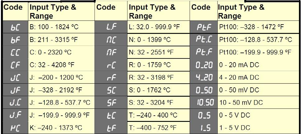
5 Connections This diagram shows all possible option combinations. The actual connections required depend on the options fitted. CAUTION: Check information label on housing for correct operating voltage before connecting supply to Power Input Fuse: V ac 1Amp anti-surge 24/48V ac/dc 315mA anti-surge Electrical shock can result in death or serious injury. Avoid contact with the leads and terminals. High voltages that may be present on leads can cause electrical shock. Note: At first power-up, or upon hardware change, the message Goto is displayed for 1 second then ConF is displayed. You must go into the configuration mode as described in section 3 of this manual. Access to other menus is denied until Configuration Mode is completed. -5-

.")
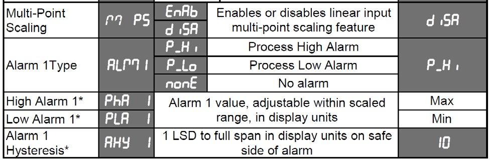
6 2. Select Mode Select mode is used to access the configuration and operation menu functions. It can be accessed at any time by holding down and pressing. The SELCt legend is shown for 1 second, followed by the legend for the current mode. Press or to choose the required mode, then press to enter. An unlock code is required to prevent unauthorised entry to Configuration, & Setup modes. Press or to enter the unlock code, then press to proceed. NOTE: Automatic return to Operator Mode after 2 minutes without key activity. 3. Configuration Mode First select Configuration mode from Select mode (refer to section 2). Press to scroll through the parameters. While this key is pressed, and up to 1 second after, the parameter legend is shown, followed by the current value. Press or to set the required value. Press to display YES?, press accept the change, otherwise parameter will revert to previous value. To exit from Configuration mode, hold down and press, to return to Select mode. Note: Parameters displayed depend on how instrument has been configured. Refer to user guide (available from your supplier) for further details. Parameters marked * are repeated in Setup Mode. -6-


7 -7-

8 -8-
9 -9-
.")
. Press or to change the value.")
10 4. Setup Mode Note: Configuration must be completed before adjusting Setup parameters. First select Setup mode from Select mode (refer to section 2). Press to scroll through the parameters (while this key is pressed, and for 1 sec after, the parameter legend is shown, then the current value). Press or to change the value. To exit from Setup mode, hold down and press to return to Select mode. Note: Parameters displayed depends on how instrument has been configured. -10-

.")
11 Note: Operator mode screens follow, without exiting from Setup mode. 5. Strain Gauge Calibration Mode Note: Configuration must be completed before adjusting Calibration parameters. First select Calibration mode from Select mode (refer to section 2). Press to scroll through the parameters (while this key is pressed, and for 1 sec after, the parameter legend is shown, then the current value). Press or to change the value. To exit from Calibration mode, hold down and press to return to Select mode. Note: Calibration mode will only be displayed if input type is set to Str_G -11-

12 When the calibration procedure begins ---- appears on the screen. Once the calibration is complete done appears on the screen. If there are faults detected with the calibration the error message ErCAL will appear. ErCAL appears during the low calibration step if the offset is greater than -10mV, for example -11mV. This could signify a faulty sensor. ErCAL appears during the high calibration step if the count value is greater than +50mV. Again this could signify a faulty sensor. Note: Performing a calibration with less than a 10mV difference between the high and low calibration values will compromise the accuracy of the instrument. 6. Special Mode Note: Configuration must be completed before adjusting Special parameters. This mode enables special features with the correct code entered; enter a value of 0 as default otherwise please refer to your supplier for information on what special features are available and which numbers invoke these. 7. Messages & Error Indications These messages indicate that the instrument may require attention, or there is a problem with the signal input connection. The message legend is shown for 1 second, followed by its value. Caution: Do not continue with the process until the issue is resolved. -12-
![Note: CHH], CLL] or OPEN may also be displayed if an incorrect input type is selected. 8. Operator Mode This mode is entered at power on, or accessed from Select mode (see section 2).](/docs-images/81/83448035/images/13-1.jpg "Note: All Configuration mode and Setup mode parameters must be set as required before starting normal operations.")
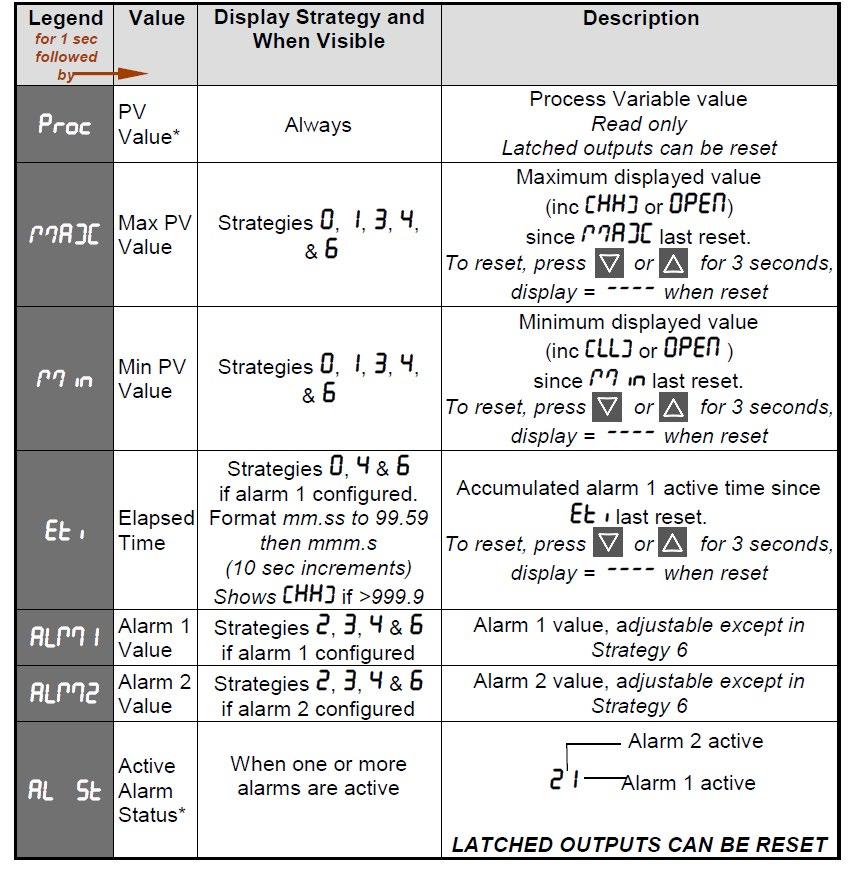
13 Note: CHH], CLL] or OPEN may also be displayed if an incorrect input type is selected. 8. Operator Mode This mode is entered at power on, or accessed from Select mode (see section 2). Note: All Configuration mode and Setup mode parameters must be set as required before starting normal operations. Press to scroll through the parameters (while this key is pressed, and for 1 sec after, the parameter legend is shown, followed by the current value). Note: All Operator Mode parameters in Display strategy 6 are read only (see disp in configuration mode), they can only be adjusted via Setup mode. -13-
14 -14-
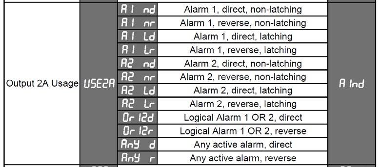
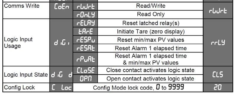
15 Alarm Indication The Active Alarm Status screen indicates any active alarms. In addition, the associated Alarm LED flashes. For latching alarm outputs, the LED flashes when the alarm condition exists, and goes to ON when the alarm condition is no longer present if the output has not yet been reset. *Resetting Latched Alarm Outputs Any latched outputs can be reset whilst the Process variable or Alarm Status screens are displayed, by pressing the or key, via the Digital Input or with a communications command via the RS485 module (if fitted). Note: Outputs will only reset if their alarm condition is no longer present. Multi-Point Scaling When enabled (Mm PS = EnAb), up to 9 breakpoints can be set to compensate for nonlinear input signals. For each breakpoint, the input scale value (ScALn) is entered in % of input span, followed by the value to be shown (dispn) in display units. Each breakpoint s input scale value must be higher than the previous value, but the display values can be higher or lower. Any scale value set to 100% becomes the last in the series. Tare Feature When Tare is enabled (TARE = ENAB), it can be used to set the displayed value to zero automatically, by making the PV Offset parameter equal, but opposite to, the current process variable value. Tare can be initiated via the Digital Input (if fitted), with a communications command via the RS485 module (if fitted) or by using the following key press sequence: Press until the process variable is displayed. Hold down and together for three seconds until the display shows YES? Release both keys and press within 3 seconds to confirm the request. The display should read 0 briefly, then begin responding to input signal changes. This will have no effect on any stored Max or Min values until they are reset. Once Reset the Max and Min value will follow the displayed value that has gone through the tare process Note: Tare request is aborted if this sequence is not followed exactly. -15-
. Hold down and press to return to Select mode.")
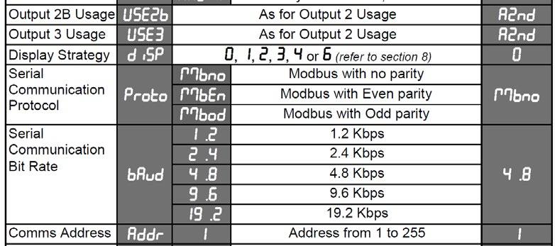
16 9. Product Information Mode First select Product information mode from Select mode (refer to section 2). Press to view each parameter (while this key is pressed, and for 1 sec after, the parameter legend is shown, followed by its value). Hold down and press to return to Select mode. Note: These parameters are all read only. 10. Serial Communications Refer to the full user guide (available from your supplier) for details. -16-
17 11. Specifications UNIVERSAL INPUT Strain Gauge: Thermocouple Calibration: 350Ω, by means of 4 or 6 wire (6 to use internal Shunt resistor) Bridge excitation: 10Vdc ± 7% Bridge Sensitivity: 1.4-4mV/V Shunt Value: From 40%to 100% Input signal Span: -25% to 125% (Approx. -10mV to +50mV) ±0.1% of full range, ±1LSD (±1 C for Thermocouple CJC). BS4937, NBS125 & IEC584. PT100 Calibration: ±0.1% of full range, ±1LSD. B S1904 & DIN43760 ( / / C). DC Calibration: ±0.1% of full range, ±1LSD. Sampling Rate: 10 per second, 16 bit resolution approximately (100ms sample time) Impedance: >10M resistive, except dc ma (5 ) and V (47k ). Sensor Break Detection: Isolation: Strain Gauge: Depending on user setting InPF can cause input to fail high scale or low scale reading. Reading will fail on either, Sig+ or Sig- loss, or incorrect excitation output <0.8mA and >50mA supply. Thermocouple/RTD: High alarms activate for sensor break. Linear 4 to 20mA, 2 to 10V and 1 to 5V DC: Low alarms activate for sensor break. Note: Sensor break not detectable on 0 to 20mA, 0 to 50mV, 0 to 5V & 0 to 10v input types. Isolated from all outputs. Universal input must not be connected to operator accessible circuits if single relay outputs are connected to a hazardous voltage source. Supplementary insulation or input grounding would then be required Logic Input Input Signal: If the Logic State setting in Config Mode = CLS, Reset or Tare occurs on an Open to Closed transition, or high (3 to 5VDC) to low (<0.8VDC) transition. If Logic State setting in Config Mode = OPN, Reset or Tare occurs on a Closed to Open transition, or low (<0.8VDC) to high (3 to 5VDC)) transition. Isolation: No isolation from inputs and other outputs. -17-
18 OUTPUTS Single Relay Contact Type & Rating: Lifetime: Isolation: Dual Relay Contact Type & Rating: Lifetime: Isolation: Linear DC Accuracy: Resolution: Isolation: Single pole double throw (SPDT), latching or non-latching action (selectable); 2A resistive at 120/240VAC. >500,000 operations at rated voltage/current. Basic Isolation from universal input and SSR outputs. Single pole single throw (SPST), latching or non-latching action (selectable); 2A resistive at 120/240VAC. >200,000 operations at rated voltage/current. Reinforced safety isolation from inputs and other outputs. ±0.1% of span 250Ω, 2kΩ). 15 3/4 bit (1 part in 52K) and updated at approx. 65ms intervals. (130ms settling time) Reinforced safety isolation from inputs and other outputs. Transmitter PSU Power Rating: 24V Tx PSU Module; Unregulated 18 to 32V DC into 400 Ω min Linear Output Module; Regulated 0.0 to 10.0V into 500 Ω min. Isolation: Reinforced safety isolation from inputs and other outputs. SERIAL COMMUNICATIONS (RS485) (option) Physical: 1200, 2400, 4800, 9600 or bps. Protocols: Selectable between Modbus and West ASCII. Isolation: Reinforced safety isolation from all inputs and outputs. OPERATING CONDITIONS (FOR INDOOR USE) Ambient Temperature: 0 C to 55 C (Operating), 20 C to 80 C (Storage). Relative Humidity: 20% to 95% non-condensing. Altitude <2000m Supply Voltage and Power: 100 to 240VAC 10%, 50/60Hz, 9VA (for mains powered versions), or 20 to 48VAC 50/60Hz 9VA or 22 to 65VDC 5W (for low voltage versions). -18-
19 ENVIRONMENTAL Standards: CE & UL EMI: EN :2013, Table 2 & Class A. Warning: This is a Class A product. In a domestic environment this product may cause radio interference in which case the user may be required to take adequate measures. Safety Considerations: UL Edition 3, Pollution Degree 2 & Installation Category II. Front Panel Sealing: IP66 (IP20 behind the panel). (IP rating tested by a UKAS accredited laboratory, but not recognized by UL). PHYSICAL Front Bezel Size: Depth Behind Panel: Weight: MANUFACTURING SITE Address: 96 x 48mm (1/8 Din Horizontal). 100mm. 0.21kg maximum. The Hyde Business Park, Brighton, BN2 4JU, United Kingdom SYMBOL EXPLANATION Caution general danger to life or limb. General information and notices are in this style. FIRMWARE This version of the manual is applicable from firmware version 04 or later. Under the Product Information Mode select I55 to display firmware version. -19-
1/32-DIN TEMPERATURE CONTROLLER INSTALLATION, WIRING AND OPERATION MANUAL FORM 3882
 1/32-DIN TEMPERATURE CONTROLLER INSTALLATION, WIRING AND OPERATION MANUAL FORM 3882 This manual is intended for use in support of installation, commissioning and configuration of the 1/32-DIN Temperature
From lab to production, providing a window into the process. Universal Input Indicator Start-up Guide. Operating Manual.
 Universal Input Indicator Start-up Guide Operating Manual -1- Contents 1. Setting up a unit straight out of the box 1.1. Entry into Configuration mode 1.2. Scrolling through Parameters and Values 1.3.
Model No Universal Input Indicator Start-up Guide
 Model No. 1480 Universal Input Indicator Start-up Guide Contents 1. Setting up a unit straight out of the box... 3 1.1. Entry into Configuration mode... 3 1.2. Scrolling through Parameters and s... 3 1.3.
ProVU 4 Advanced Temperature & Process Controller
 ProVU 4 Advanced Temperature & Process Controller 1/4 DIN Format Graphical / text LCD Display (red/green) Profiling option Datalogging option (data, alarms & events) 5 language (English, French, German,
DUAL COLOUR DISPLAY TEMPERATURE INDICATOR. Product Manual
 1 -DIN 8 DUAL COLOUR DISPLAY TEMPERATURE INDICATOR Product Manual -2 HOW TO USE THIS MANUAL This manual comprises two volumes: 1 8-DIN DUAL COLOUR DISPLAY TEMPERATURE INDICATOR Product Manual Contents
DUAL COLOUR DISPLAY DC PROCESS INDICATOR. Product Manual
 1 -DIN 8 DUAL COLOUR DISPLAY DC PROCESS INDICATOR Product Manual 59136-2 HOW TO USE THIS MANUAL This manual comprises two volumes: 1 8-DIN DUAL COLOUR DISPLAY DC PROCESS INDICATOR Product Manual Contents
TECHNICAL DATA SHEET. ProVU 4 Advanced Temperature Controller. Features. Description
 ProVU 4 Advanced Temperature Controller ¼ DIN Format Graphical / text LCD Display (red/green) Profiling option Datalogging option (data, alarms & events) 5 language (English, French, German, Italian, Spanish)
Tempco Instruction Manual
 Tempco Instruction Manual 1/16 DIN Solid State Temperature Controller Relay Output Solid State Output For Heating Model Numbers: TEC-901, TEC-902, TEC-905 Temperature controls in this series are designed
SX90 Process Controller
 Local regulations may restrict the use of this product to below the conditions quoted. In the interests of development and improvement of the product, we reserve the right to change the specification without
UDC 1000 and UDC 1500 MICRO-PRO SERIES UNIVERSAL DIGITAL CONTROLLERS
 UDC 1000 and UDC 1500 MICRO-PRO SERIES UNIVERSAL DIGITAL CONTROLLERS EN0I-6041 12/99 PRODUCT SPECIFICATION SHEET OVERVIEW The UDC 1000 and UDC 1500 are microprocessor-based 1/16 DIN and 1/8 DIN controllers
Contents. Temperature & Process Measurement Indicators Setup Guide
 Contents Introduction... 2 Installation... 3 Connections... 5 Connecting the Sensor... 6 Powering the Instrument... 7 Operator Functions... 8 The Setup Menus... 9 Configuration Menu Map... 12 Menu Options...
Operating Manual. Dynisco ATC990 Graphical 1/4 DIN Process Controller Concise Product Manual
 Dynisco ATC990 Graphical 1/4 DIN Process Controller Concise Product Manual Operating Manual -1- The following symbols are used on the product labels: Caution, refer to installation manual when connecting
PSR-PC50. SIL 3 coupling relay for safety-related switch on. Data sheet. 1 Description
 SIL 3 coupling relay for safety-related switch on Data sheet 105818_en_01 PHOENIX CONTACT 2014-08-18 1 Description The PSR-PC50 SIL coupling relay can be used for power adaptation and electrical isolation
LAUREL. Laureate Digital Panel Meter for Process and Ratiometric Signals ELECTRONICS, INC. Features. Description
 LAUREL ELECTRONICS, INC. Laureate Digital Panel Meter for Process and Ratiometric Signals Features Reads process signals from ±200 mv to ±600V or ±2 ma to ±5A full scale Ratiometric mode for bridges and
ASTAT XB/XBm Remote Operator
 ASTAT XB/XBm Remote Operator User Manual 1 Introduction 1.1 Important User Information Observe all necessary safety precautions when controlling the soft starter remotely. Alert personnel that machinery
1/4, 1/8 and 1/16 DIN Controllers, Indicators & Profilers User Guide Manual Part Number: Price: $15.00
 1/4, 1/8 and 1/16 DIN Controllers, Indicators & Profilers User Guide Manual Part Number: 59321-1 Price: $15.00 This manual supplements the Concise Product manual supplied with each instrument at the time
TRACKER 220 SERIES. Digital Panel Indicators. A Complete Range of Universal Input Digital Panel Indicators for Temperature and Process Measurement
 TRACKER 220 SERIES Digital Panel Indicators A Complete Range of Universal Input Digital Panel Indicators for Temperature and Process Measurement TRACKER 220 SERIES INDICATORS Universal Input Analogue Output
The Tracker 220 Series A Complete Range of Universal Input Digital Panel Indicators for Temperature and Process Measurement
 Acquisition Measurement Control The Tracker 220 Series A Complete Range of Universal Input Digital Panel Indicators for Temperature and Process Measurement TRACKER 220 SERIES INDICATORS Universal Input
RSTI-EP Slice I/O. Analog Input Modules `EP-3164, EP-3264, EP-3124, EP-3368, EP-3468 EP-3704, EP GFK-2960B November 2017
 November 2017 Module Status LED Channel Status LEDs Digital Input Connector Ground 24 V DC FE Analog Input Module RSTI-EP Slice I/O Analog Input Modules `EP-3164, EP-3264, EP-3124, EP-3368, EP-3468 EP-3704,
West Instruments. The MLC compact multi-loop controller... MLC ends the control or integration compromise
 The MLC 9000+ compact multi-loop controller... MLC 9000+...ends the control or integration compromise Why the MLC 9000+? Use the MLC 9000+ as a discrete controller mounted behi either as a stand-alone
Soft Starter Remote Operator. Section 1.0 Introduction 1.1 Important user information General Manual description...2.
 Section 1.0 Introduction 1.1 Important user information... 2 1.2 General... 2 1.3 Manual description...2 Contents Section 2.0 Specification 2.1 General technical data...3 2.2 Dimensions...3 Section 3.0
Controllers & Indicators User Guide
 1 / 4 -DIN, 1 / 8 -DIN & 1 / 16 -DIN Controllers & Indicators - Product Manual 1 / 4, 1 / 8 and 1 / 16 DIN Plus Series Controllers & Indicators User Guide Manual Part Number: 59305-6 Price: 12.00 $20.00
PRO-EC44 Single or two loop advanced controller with graphic display
 PRO-EC44 Single or two loop advanced controller with graphic display KEY FEATURES 1/4 DIN Format Single or Two Loop Graphical / text LCD Display (red/green) USB configuration and data access Profiler 256
Temperature/Process Controllers Manual
 3200 SERIES Temperature/Process Controllers Manual The innovative range of 3200 controllers offer precision control of temperature and other process variables together with a host of advanced features
Introduction. Features. Index
 Introduction A new standard of performance and functionality in a compact preset counter. The V454501 Single Preset Counter offers a pre-settable counter with full calibration for a variety of applications.
DIGITAL INDICATING CONTROLLER
 DB1000 SERIES DIGITAL INDICATING CONTROLLER The DB1000 series is a 96 96mm digital indicating controller with the indicating accuracy of ±0.1% and the control cycle of approximately 0.1 seconds. Various
RSTI-EP Slice I/O. Analog Input Modules `EP-3164, EP-3264, EP-3124, EP-3368, EP-3468 EP-3664, EP-3704, EP GFK-2960F September 2018
 September 2018 Module Status LED Channel Status LEDs Digital Input Connector Ground 24 V DC FE Analog Input Module RSTI-EP Slice I/O Analog Input Modules `EP-3164, EP-3264, EP-3124, EP-3368, EP-3468 EP-3664,
MODEL: M5DY SEN TRONIC AG CURRENT LOOP SUPPLY. [2] POWER INPUT AC Power M: V AC (Operational voltage range V, Hz)
![MODEL: M5DY SEN TRONIC AG CURRENT LOOP SUPPLY. [2] POWER INPUT AC Power M: V AC (Operational voltage range V, Hz)](/thumbs/90/103899684.jpg "MODEL: M5DY SEN TRONIC AG CURRENT LOOP SUPPLY. [2] POWER INPUT AC Power M: V AC (Operational voltage range V, Hz)") Super-mini Terminal Block Signal Conditioners M5-UNIT CURRENT LOOP SUPPLY Functions & Features Powering a 0 ma DC current loop Applicable to smart transmitters Isolation between the input and output Fast
Super-mini Terminal Block Signal Conditioners M5-UNIT CURRENT LOOP SUPPLY Functions & Features Powering a 0 ma DC current loop Applicable to smart transmitters Isolation between the input and output Fast
LAUREL ELECTRONICS, INC.
 LAUREL ELECTRONICS, INC. Laureate RTD Temperature Panel Meter / Controller Features Factory calibrated for 100Ω platinum, 10Ω copper & 120Ω nickel RTDs 2, 3 or 4-wire connection with lead resistance compensation
Digital ac/dc (24V) Input Module
 Input Module") Installation Instructions Digital ac/dc (24V) Input Module Catalog Number 1771-IND, Series C Topic Page Important User Information 2 Before You Begin 3 Power Requirements 3 Prevent Electrostatic Discharge
Installation Instructions Digital ac/dc (24V) Input Module Catalog Number 1771-IND, Series C Topic Page Important User Information 2 Before You Begin 3 Power Requirements 3 Prevent Electrostatic Discharge
S-14 S-14. Compact Digital Multimeter. Compact Digital Multimeter
 S-14 Compact Digital Multimeter S-14 Compact Digital Multimeter SAFETY INFORMATION The following safety information must be observed to insure maximum personal safety during the operation at this meter
SAFETY RELAY YRB-4EML-31S MAIN FEATURES
 SAFETY RELAY TYPE 4 SAFETY PROTECTION DEVICE FOR SAFETY LIGHT CURTAINS/BARRIERS MAIN FEATURES For safety light curtains and access control barriers, emergency stop, door switch Safety Integrity Level (SIL)
HL100 Controller Operator's Manual
 2230051/1 IM-S27-11 CH Issue 1 HL100 Controller Operator's Manual Volume 1 Operating instructions 1 Operator mode 2 Set up mode 3 RS485 serial communications Volume 2 Installation and configuration instructions
Omni. User Manual. Economic Self-Tune PID Temperature Controller. Omni 96. Omni 72 72X72. Omni ~ 265 V AC SUPPLY
 Omni Economic Self-Tune PID Temperature Controller Omni 7 Omni 4 6 5 4 3 1 7X7 7 1 11 5 ~ 65 V AC SUPPLY Omni 6 CONTENTS 1. PANEL MOUNTING & ELECTRICAL CONNECTIONS 1. FRONT PANEL : LAYOUT AND OPERATION
ACCESS 9340/9360 Meter Input/Output Module
 Installation Manual PMIM-IOMOD-0208 ACCESS 9340/9360 Meter Input/Output Module 9340-60-I/O2222 and 9340-60-I/O26 HAZARD CATEGORIES AND SPECIAL SYMBOLS Read these instructions carefully and look at the
User Manual. 400Amp AC Clamp Meter + NCV. Model MA430. Additional User Manual Translations available at
 User Manual 400Amp AC Clamp Meter + NCV Model MA430 Additional User Manual Translations available at www.extech.com Introduction Congratulations on your purchase of this Extech MA430 Clamp Meter. This
JUMO Quantum PID100/PID200/PID300
 Data sheet 702020 Page 1/12 JUMO Quantum PID100/PID200/PID300 Universal PID Controller Series Brief description The Quantum series is available in the three DIN formats 48 mm x 48 mm, 48 mm x 96 mm, and
Digital Indicating Controllers. JC Series. High performance controllers...at the lowest prices anywhere! Toll Free
 Digital Indicating Controllers JC Series High performance controllers...at the lowest prices anywhere! www.mod-tronic.com Toll Free 1-800 794-5883 Standard Features Structure Units available in standard
Mini Digital Multimeter
 User Manual Mini Digital Multimeter Model MN15A Additional User Manual Translations available at www.extech.com Introduction Congratulations on your purchase of the Extech MN15A MultiMeter. The MN15A offers
LC0 DVP
 2010-09-24 5012602300-2LC0.... DVP-1071070-01 POWER RUN ERROR L.V NET ZER O MAX MOTION NET ZER O MAX MOTION CH1 CH2 SHD SHD ENGLISH Thank you for choosing Delta s DVP series PLC. Delta releases DVP02LC-SL
UDC1200 and UDC1700 MICRO-PRO SERIES UNIVERSAL DIGITAL CONTROLLERS
 UDC1200 and UDC1700 MICRO-PRO SERIES UNIVERSAL DIGITAL CONTROLLERS 51-52-03-35 11/06 PRODUCT SPECIFICATION SHEET OVERVIEW The UDC1200 & UDC1700 are microprocessor-based 1/16 DIN and 1/8 DIN controllers
Controllers & Indicators User Guide
 1 / 4, 1 / 8 and 1 / 16 DIN Plus Series Controllers & Indicators User Guide Manual Part Number: 59305-4 Price: 12.00 $20.00 18.00 This manual supplements the Concise Product manual supplied with each
LAUREL. Laureate RTD Temperature Panel Meter / Controller ELECTRONICS, INC. Features. Description. Specifications
 LAUREL ELECTRONICS, INC. Laureate RTD Temperature Panel Meter / Controller Features Factory calibrated for 100Ω platinum, 10Ω copper & 120Ω nickel RTDs 2, 3 or 4-wire connection with lead resistance compensation
TRACKER 240 SERIES. Load Cell and Weighing Indicators. A Precision Measurement Instrument with Outstanding Features
 TRACKER 240 SERIES Load Cell and Weighing Indicators A Precision Measurement Instrument with Outstanding Features TRACKER 240 SERIES INDICATORS Ratiometric Measurement Tare and Auto Transducer Excitation
USER MANUAL MULTI COLOR TOUCH SCREEN PAPERLESS RECORDER TPLR-96 Series
 USER MANUAL MULTI COLOR TOUCH SCREEN PAPERLESS RECORDER TPLR-96 Series TEMPSEN DEVICES Plot No : 2&3, Balaji Nagar, 4 th Street, Mettukuppam, Thoraipakkam, Chennai-600097 Tele fax : +91-44-24581758,Mobil
PU5 5-digit digital panel meter in 96x48 mm (BxH) Universal measuring inputs: Pt100, current, voltage, shunt, thermocouple, resistance
 Universal measuring inputs: Pt100, current, voltage, shunt, thermocouple, resistance") PU5 5-digit digital panel meter in 96x48 mm (BxH) Universal measuring inputs: Pt100, current, voltage, shunt, thermocouple, resistance red display of -9999 99999 digits installation depth: 120 mm without
PU5 5-digit digital panel meter in 96x48 mm (BxH) Universal measuring inputs: Pt100, current, voltage, shunt, thermocouple, resistance red display of -9999 99999 digits installation depth: 120 mm without
/8 DIN Universal Process Indicator
 Data Sheet SS/_ High visibility LED display the clearest view of your process status.% measurement accuracy precise indication of process measurement Analog and relay outputs as standard alarm and retransmission
LBVR1718. Description. Features channel paperless recorder
 LBVR1718 18 - channel paperless recorder Description It is the world first paperless recorder of the same size in highest resolution 640x480 pixels VGA TFT display, infrared detector, maximum 18 channels,
1 / 8 -DIN & 1 / 16 -DIN Controller & Indicator Manual. 1 / 8 & 1 / 16 DIN Controller and Indicator. Product Manual. Manual Part Number:
 1 / 8 & 1 / 16 DIN Controller and Indicator Product Manual Manual Part Number: 51-52-25-122 This manual supplements the Concise Product manual supplied with each instrument at the time of shipment. Information
SINGLE-CHANNEL PROCESS CONTROLLERS & TEMP. DISPLAYS D3820/D3830 Series
 The Digitec Series D3800 Panel Meters offer many features and performance capabilities to suit a wide range of industrial applications. The D3820 and D3830 are available in the ranges of 4-20mA, 0-10 VDC,
Autoranging True RMS Multimeter User Manual
 Autoranging True RMS Multimeter User Manual Please read this manual before switching the unit on. Important safety information inside. Contents Page 1. Safety Information... 4 2. Safety Symbols... 5 3.
Operating Manual RISH DPM Hz
 Operating Manual RISH DPM 72mm x 144mm 96mm x 96mm 48mm x 96mm 2-60-006-00-00512_Rev. B - 7/2016 DIGITAL MULTIFUNCTION INSTRUMENT Programmable Digital Panel Meter Installation & Operating Instructions
Mini Digital Multimeter
 User's Guide Mini Digital Multimeter Model MN15 99 Washington Street Melrose, MA 02176 Phone 781-665-1400 Toll Free 1-800-517-8431 Visit us at www.testequipmentdepot.com Back to the Extech MN15/MN16 Series
MODCELL 2050R Single Loop Controllers
 Isolated universal process and remote set-point input Four internal set-points No jumpers required to define instrument parameters Ratio/bias on process and remote set-point Totalizer Ramp/soak profile
Wall-/Pipe Mounted Universal Process Indicator
 Data Sheet SS/_8 Wall-/Pipe Mounted Universal Process Indicator High visibility LED display the clearest view of your process status 0.1% measurement accuracy precise indication of process measurement
R1M-GH BEFORE USE... POINTS OF CAUTION INSTRUCTION MANUAL PC RECORDER MODEL. (thermocouple or DC input, 16 points)
") INSTRUCTION MANUAL PC RECORDER (thermocouple or DC input, points) MODEL BEFORE USE... Thank you for choosing M-System. Before use, please check contents of the package you received as outlined below. If
INSTRUCTION MANUAL PC RECORDER (thermocouple or DC input, points) MODEL BEFORE USE... Thank you for choosing M-System. Before use, please check contents of the package you received as outlined below. If
EL1142 Series. IEC / IEEE 1613 Hardened 2-Port 10/100BASE-TX to 2-Port 100BASE-FX Media Converter. User s Guide
 EL1142 Series IEC 61850 / IEEE 1613 Hardened 2-Port 10/100BASE-TX to 2-Port 100BASE-FX Media Converter User s Guide All Rights Reserved Dissemination or reproduction of this document, or its contents,
D6030S - D6030D INSTRUCTION MANUAL. D SIL 3 Switch/Proximity Detector Repeater Relay Output. Models D6030S, D6030D
 D600S - D600D INSTRUCTI MANUAL SIL Switch/Proximity Detector Repeater Relay, DIN Rail, Models D600S, D600D D600 - SIL Switch/Proximity Detector Repeater Relay G.M. International ISM0- Characteristics General
OPERATING INSTRUCTIONS 7 SERIES STATIC GENERATORS
 OPERATING INSTRUCTIONS 7 SERIES STATIC GENERATORS GB Contents Page 1 Introduction 4 2 Safety 5 3 Use 6 4 Checking on Delivered Equipment 6 5 General Specification and Dimensions 7 6 Positioning 10 7 Operating
PanelView Plus/VersaView CE Terminals and Display Modules
 Installation Instructions PanelView Plus/VersaView CE Terminals and Display Modules (Catalog Numbers 2711P-xxxxxx, 6182H-xxxxxx) English Inside: Overview...2 For More Information...2 Modular Components...3
OPERATING INSTRUCTION
 OPERATING INSTRUCTION AUTORANGING MULTIMETER MAX Ω F C 10A MAX every 15 min. COM V SAFETY INFORMATION The following safety information must be observed to insure maximum personal safety during the operation
Veeder-Root brand Series S628 Strain Gauge (S628-6XXX)
") Introduction Your Veeder-Root brand S628 Strain Gauge is one model in a family of 1/8 DIN units which offers breakthrough display technology as well as easy-to-program single-line parameters. Designed
Introduction Your Veeder-Root brand S628 Strain Gauge is one model in a family of 1/8 DIN units which offers breakthrough display technology as well as easy-to-program single-line parameters. Designed
ProVU 4 Advanced Temperature & Process Controller
 ProVU 4 Advanced Temperature & Process Controller 1/16 DIN Format Graphical / text LCD Display (red/green) Profiling option Datalogging option (data, alarms & events) 5 language (English, French, German,
PSR-MS60. Safety relay for emergency stop, safety door and light grid monitoring. Data sheet. 1 Description
 SILCL IEC 62061 Safety relay for emergency stop, safety door and light grid monitoring Data sheet 106171_en_01 PHOENIX CONTACT 2015-05-19 1 Description Intended Use The PSR-MS60 safety relay can be used
Strip Chart Recorders Specification Sheet
 4101C, 4101M 4102C, 4102M MODELS Continuous Pen Recording 1, 2, 3 or 4 Pens Multi-point Recording Providing 6 Colour traces High Visibility Display 4101C, 4101M Clear Analogue Scale 4102C, 4102M Large
The power behind competitiveness. Delta Infrasuite Power Management. Power Distribution Unit. User Manual.
 The power behind competitiveness Delta Infrasuite Power Management Power Distribution Unit User Manual www.deltapowersolutions.com Save This Manual This manual contains important instructions and warnings
Analyzer/Controller. ph/orp HART. Model 54e ph/orp ESSENTIAL INSTRUCTIONS WARNINGS RISK OF ELECTRICAL SHOCK
 Instruction Sheet PN 51A-54epH/rev J October 2010 ph/orp HART Model 54e ph/orp Analyzer/Controller For additional information, please visit our website at www.emersonprocess.com/raihome/liquid/. ESSENTIAL
The CAL range of temperature controllers
 The CAL range of temperature controllers CAL Temperature Controllers Auto-tuning P.I.D. Controllers with RS232/485 Communication, Charting and Logging Software The CAL range of temperature controllers
PSR UC/ESAM4/3X1/1X2/B
 Safety relay for emergency stop and safety door monitoring Data sheet 105318_en_02 PHOENIX CONTACT 2014-06-13 1 Description The safety relay can be used in safety circuits according to EN 60240-1 and IEC
SLIMCON-6 24V DC POWERED ISOLATING SIGNAL CONVERTER
 SLIMCON-6 24V DC POWERED ISOLATING SIGNAL CONVERTER Whilst every effort has been taken to ensure the accuracy of this document, we accept no responsibility for damage, injury, loss or expense resulting
- SELF-TUNING PID ALGORITHM - INTUITIVE COLOR DISPLAY WITH TEXT MESSAGING - UNIVERSAL PROCESS AND TC/RTD INPUTS - MULTI- FUNCTION RAMP- DWELL/PROCESS
 ELK. ETK COMPACT BASIC CONTROL - SELF-TUNING PID ALGORITHM - INTUITIVE COLOR DISPLAY WITH TEXT MESSAGING - UNIVERSAL PROCESS AND TC/RTD INPUTS - MULTI- FUNCTION RAMP- DWELL/PROCESS TIMER - SOFT START OUTPUT
USER MANUAL MULTI COLOR TOUCH SCREEN PAPERLESS RECORDER MODEL : ARC2020
 USER MANUAL MULTI COLOR MODEL : ARC2020 ACCSYS ELECTRONICS 140/6B, GOLDEN INDUSTRIAL ESTATE, JAWAHARLAL NEHRU ROAD, GERUGAMBAKKAM, CHENNAI - 600122 Tel: 044 60505599 / 60505511 E-mail : sales@accsyselectronics.com
R1M-GH BEFORE USE... POINTS OF CAUTION INSTRUCTION MANUAL PC RECORDER MODEL. (thermocouple or DC input, 16 points)
") INSTRUCTION MANUAL PC RECORDER (thermocouple or DC input, points) MODEL RM-GH BEFORE USE... Thank you for choosing M-System. Before use, please check contents of the package you received as outlined below.
INSTRUCTION MANUAL PC RECORDER (thermocouple or DC input, points) MODEL RM-GH BEFORE USE... Thank you for choosing M-System. Before use, please check contents of the package you received as outlined below.
Zenex-ultra Ultra Precision (0.01 C) Self-Tune PID Temperature Controller with Programmable Timer
 Self-Tune PID Temperature Controller with Programmable Timer") Ultra Precision (0.01 C) Self-Tune PID Temperature Controller with Programmable Timer CONTENTS 1. FRONT PANEL LAYOUT 1. BASIC OPERATION 3. PAGES & PARAMETERS 3 4. INSTALLATION PARAMETERS 5 5. CONFIGURATION
Ultra Precision (0.01 C) Self-Tune PID Temperature Controller with Programmable Timer CONTENTS 1. FRONT PANEL LAYOUT 1. BASIC OPERATION 3. PAGES & PARAMETERS 3 4. INSTALLATION PARAMETERS 5 5. CONFIGURATION
LAUREL. Laureate Digital Panel Meter for Load Cell & Microvolt Input ELECTRONICS, INC. Features. Description
 Description LAUREL ELECTRONICS, INC. Features Laureate Digital Panel Meter for Load Cell & Microvolt Input 20, 50, 100, 250 & 500 mv ranges Span adjust from 0 to ±99,999, zero adjust from -99,999 to +99,999
The PM1000 series is a universal 4 digit LED plug-on display for transmitters with 4-20mA 2 wire output and fitted with DIN43650 connector.
 PM1000 SERIES PLUG-ON DISPLAY BRIGHT LED DISPLAY INDICATION RANGE -999 TO +9999 FITS TO DIN 43650 CONNECTOR PLUG-ON TO ANY TRANSMITTER WITH 4-20MA OUTPUT EASY TO SCALE ON SITE ROBUST DESIGN SET POINT OPTION
LCI User Manual mantracourt.com
 LCI User Manual mantracourt.com LCI Load Cell Junction Box with Fault Monitor Contents Chapter 1 Introduction to the LCI... 2 Chapter 2 Installing the LCI... 3 Chapter 3 Setting up the LCI... 4 Sequence
12-36 VDC/12-24 VAC Power Option 4-Digit Display, 0.56 (14.2 mm) or 1.20 (30.5 mm)
 or 1.20 (30.5 mm)") 4-20 ma & Relay Output Features 4-20 ma, ± 10 V, TC & RTD Inputs 12-36 VDC/12-24 VAC Power Option 4-Digit Display, 0.56 (14.2 mm) or 1.20 (30.5 mm) 24 VDC @ 200 ma Transmitter Power Supply Options Type
4-20 ma & Relay Output Features 4-20 ma, ± 10 V, TC & RTD Inputs 12-36 VDC/12-24 VAC Power Option 4-Digit Display, 0.56 (14.2 mm) or 1.20 (30.5 mm) 24 VDC @ 200 ma Transmitter Power Supply Options Type
DM-918 OPERATIONS MANUAL AUTORANGING MULTIMETER
 DM-918 OPERATIONS MANUAL AUTORANGING MULTIMETER SAFETY INFORMATION The following safety information must be observed to ensure maximum personal safety during the operation of this meter: This meter is
C160 Wall-/Pipe Mounted Universal Process Indicator
 Data sheet DS/ EN Rev. I Wall-/Pipe Mounted Universal Process Indicator reliable process indicator, wherever it s needed High visibility LED display the clearest view of your process status 0.1% measurement
DT1102 V (PS) Fully Configurable Galvanic Isolator. Operating Instructions
 Fully Configurable Galvanic Isolator. Operating Instructions") (PS) Fully Configurable Galvanic Isolator Operating Instructions Contents 1. About this document...4 1.1. Function... 4 1.2. Target group... 4 1.3. Symbolism used... 4 2. For your safety...5 2.1. Authorized
(PS) Fully Configurable Galvanic Isolator Operating Instructions Contents 1. About this document...4 1.1. Function... 4 1.2. Target group... 4 1.3. Symbolism used... 4 2. For your safety...5 2.1. Authorized
Trident and Trident X2 Digital Process and Temperature Panel Meter
 Sign In New User ISO 9001:2008 Certified Quality System Home Products Online Tools Videos Downloads About Us Store Contact Policies Trident and Trident X2 Digital Process and Temperature Panel Meter Products
The IQ300 wall mount load cell indicator is a precision digital indicator for load cell and strain gauge applications.
 IQ300 Wall Mount Load Cell Indicator Data sheet English 1.01 Introduction The IQ300 wall mount load cell indicator is a precision digital indicator for load cell and strain gauge applications. The high
Pro-EC44 2-Loop Graphical Profile Controller & Recorder Pro-EC44 User Guide
 Pro-EC44 2-Loop Graphical Profile Controller & Recorder Pro-EC44 User Guide 59540-4. This user guide covers firmware version 1.9 or later of the West Pro-EC44 controller. This manual supplements the Concise
PGR-3200 MANUAL INSULATION MONITOR
 Tel: +1-800-832-3873 E-mail: techline@littelfuse.com www.littelfuse.com PGR-3200 MANUAL INSULATION MONITOR REVISION 3-E-040918 Copyright 2018 by Littelfuse, Inc. All rights reserved. Document Number: PM-1025-EN
MYRIAD QLC 4-CHANNEL MONITOR/CONTROLLER INSTRUCTION MANUAL
 MYRIAD QLC 4-CHANNEL MONITOR/CONTROLLER INSTRUCTION MANUAL VISIT OUR WEBSITE SIGMACONTROLS.COM MYR QLC MANUAL 013114 2 TABLE OF CONTENTS INTRODUCTION 3 Ordering Information Specifications Features WIRING
PSR DC/ESP4/2X1/1X2
 PSR-...- 24DC/ESP4/2X1/1X2 Safety relay for emergency stop and safety door monitoring Data sheet 100516_en_05 PHOENIX CONTACT 2013-11-21 1 Description The safety relay can be used for emergency stop and
TC Type Range Conformity Error. J -210 C to +760 C (-347 F to F) ±0.09 C (±0.16 F) K -244 C to C (-408 F to F) ±0.1 C (±0.
 ±0.09 C (±0.16 F) K -244 C to C (-408 F to F) ±0.1 C (±0.") LAUREL ELECTRONICS, INC. Laureate Thermocouple Panel Meter / Controller Features Factory calibrated for thermocouple types J, K, T, E, N, R, S Entire range of each thermocouple in one scale Highly accurate
LAUREL ELECTRONICS, INC. Laureate Thermocouple Panel Meter / Controller Features Factory calibrated for thermocouple types J, K, T, E, N, R, S Entire range of each thermocouple in one scale Highly accurate
GS400. Electronic Auto-Ranging DIN Panel Mounted Positioner
 GS400 Electronic Auto-Ranging DIN Panel Mounted Positioner Features * AC (115/230V) and DC (24V) versions available. * Accepts either current or voltage command signal and either current, voltage, or three
2 in1 LAN Tester & Multimeter. Model: PCE-LT 1
 www.pce-industrial-needs.com Tursdale Technical Services Ltd Unit N12B Tursdale Business Park Co. Durham DH6 5PG United Kingdom Phone: +44 ( 0 ) 191 377 3398 Fax: +44 ( 0 ) 191 377 3357 info@tursdaletechnicalservices.co.uk
DS 96/48 PK. Digital indicator. Manual 42/33-90 EN Rev. 00 DIM
 DS 96/48 PK Digital indicator Manual 42/33-90 EN Rev. 00 A1 A2 DIM E DS 96/48 PK Digital Indicator Manual Document No. 42/33-90 EN Edition 06.01 Revision 00 Manufacturer: ABB Automation Products GmbH Höseler
INSTALLATION MANUAL. LC 200 Electronic Overload Guard. Software versione PW0501 R 0.3
 INSTALLATION MANUAL LC 200 Electronic Overload Guard Software versione PW0501 R 0.3 CONTENTS MAIN FEATURES LC 200 TECHNICAL FEATURES Page 2 SYMBOLS Page 3 WARNINGS Page 3 IDENTIFICATION DATA PLATE Page
ABB Instrumentation. Specification DataFile COMMANDER 100. the-easy-to use 1. /8 DIN controller with extensive application capabilities
 COMMANDER Universal Process Controller Specification DataFile PID controller with one shot autotune single loop, heat/cool and ramp/soak as standard Quick code, front face or PC configuration easy commissioning
The Programmable 4-Way Relay Card is an optional peripheral unit that provides four individually programmable relay output circuits.
 Peripheral Relay The Programmable 4-Way Relay Card is an optional peripheral unit that provides four individually programmable relay output circuits. Up to 16 Cards can be connected to a multi-loop panel
Model SC500. Programmable Single-Channel Transducer Indicator/Conditioner DESCRIPTION FEATURES
 Programmable Single-Channel Transducer Indicator/Conditioner DESCRIPTION The SC series models are self-calibrating microprocessorbased transducer signal conditioners when used with sig mod equipped transducers.
Universal power supply
 Honeywell UDC1200 and UDC1700 MICRO-PRO SERIES UNIVERSAL DIGITAL CONTROLLERS 51-52-03-35 5/03 PRODUCT SPECIFICATION SHEET OVERVIEW The UDC1200 & UDC1700 are microprocessor-based 1/16 DIN and 1/8 DIN controllers,
100mm Process Indicator Recorder
 Data Sheet SS/_3 100mm Process Indicator Recorder One or two pen continuous line 100mm recorder universal input for thermocouple, RTD, mv, ma and V Clear, 5-digit LED display high visibility, wide viewing
Operating Instructions VEGAMET 381
 Operating Instructions VEGAMET 381 in out Contents Contents 1 About this document... 4 1.1 Function... 4 1.2 Target group... 4 1.3 Symbolism used... 4 2 For your safety... 6 2.1 Authorised personnel...
Alarm Unit DG 3200 Control And Monitor Standard Signals
 Alarm Unit DG 3200 Control And Monitor Standard Signals With the Alarm Unit DG 3200 DRAGO is extending its offer on high-functional and high-reliable components of the interface technique. The Alarm Unit
H Series PLC. ! : Indicates Compulsion. EH-150 Analog input module EH-AXH8M Instruction manual. Safety precautions DANGER CAUTION COMPULSION
 H Series PLC EH-150 Analog input module EH-AXH8M Instruction manual Thank you for purchasing a Hitachi Programmable Logic Controller. To operate it safely, please read this instruction manual and all the