Installation procedure Hands free reader: L51 - R1x Variant
|
|
|
- Alice Matthews
- 5 years ago
- Views:
Transcription


1 STId 2010 NI1023A04 06/07/2010 P. 1 / 13
2 I. Characteristics... 3 II. Wiring R11 TTL Variant: R12 RS232 Variant Protocol 5C: R13 RS485 Variant Protocol 7S:... 6 III. Calibration... 7 IV. Mechanic Antenna overview: Reader overview V. Reader installation examples STId 2010 NI1023A04 06/07/2010 P. 2 / 13
3 I. Characteristics Power supply: VDC Min Consumption:... 0, 3 to 1.1A depending on calibration Communication:... ISO2 or Wiegand, Open collector TTL lines... RS232 Protocol 5C (RS232)... RS485 Protocol 7S (RS485) Pin out:... 8 points connector + 2 points connector Reading distance: Credit card tags (CCT type)...max. 50 cm (*) Key fobs (PCS type).max 30 cm (*) High distance tags (TVL type) max. 80 cm (*) (*) Performance for a non perturbed environment. Mechanic: Antenna: Dimensions: 408 x 288 mm Thickness 13 mm Electronic case: Black PS choc IP65 Recommendations / Limits: If 2 (or more) readers are installed too close, it can cause a coupling. The readers will not be able to read tags or a tag will be read by each reader at the same time. Do not install the reader near to a closed conductor circuit. Do not install the reader on a metallic support Do not install the reader close to a metallic ground. In this case, respect the minimum distance, between the antenna and the ground, which are 20 cm with the side of the antenna and 50 cm with the back of the antenna. Do not forget to connect the 0V to a clean ground. (See the installation examples at the end of this document) Unfavorable cases Avoid installing the reader close to perturbing electromagnetic field like: Informatics data transmission cables Energy transmission cables Screen display Equipment with no EMC conformity Power supply units Variators Power Backups Detection loop STId 2010 NI1023A04 06/07/2010 P. 3 / 13
.")
4 II. Wiring 1. R11 TTL Variant: Connect the power supply (0V, +12V) and the data lines to the host. The maximum distance between the host and the reader is 100m. Recommended cables: Multi-pair shielded cable (diameter min 5mm, max 8mm to ensure water resistance). In case of remote power supply: N Data/Clock (2x) Wiegand (3x) 1 pair 6/10 until 30 meters (98,43 ft). 2 pairs 6/10 until 60 meters ( ft). 3 pairs 6/10 until 100 meters ( ft). Or 1 pair 9/10 until 50 meters ( ft). 2 pairs 9/10 until 100 meters ( ft). 1 0V 0V 2 +12V +12V 3 Code Data 0 4 Data Data 1 5 Clock Clock 6 Mode Mode 7 Green LED Green LED 8 Red LED Red LED 9 0V 0V 10 12V +12V Main board view: 1 0V 2 +12V 3 Code / Data0 4 Data / Data1 5 Clock 6 Mode 7 Green LED 8 Red LED 9 0V V These jumpers are used in the case of galvanique insulation. In this case, outputs are 0V + 12V With insulation Without insulation STId 2010 NI1023A04 06/07/2010 P. 4 / 13
5 2. R12 RS232 Variant Protocol 5C: 1 0V 2 +12V 3 Setup 4 Tx 5 Rx Connect the power supply (0V, +12V) and the data lines to the host. The maximum distance between the host and the reader is 15m. Recommended cables: Multi-pair shielded cable (diameter min 5mm, max 8mm to ensure water resistance). N Description 0V +12V Setup Tx Rx DB9 Connector STId 2010 NI1023A04 06/07/2010 P. 5 / 13
6 3. R13 RS485 Variant Protocol 7S: 1 0V 2 +12V 3 Setup 4 L+ 5 Connect the power supply (0V, +12V) and the data lines to the host. The maximum distance between the host and the reader is 1000m. Recommended cables: Multi-pair shielded cable (diameter min 5mm, max 8mm to ensure water resistance). N Description 0V +12V Setup L+ Max number of readers on the same bus: 16max. End of line resistors: R=120Ω, ¼ Watt. These resistors must be connected on the connector of the first and last equipment on the bus. L+ and on a twisted pair. CONCENTRATEUR L+ Résistances de fin de ligne (120Ω) LMS/LXS Reader R13 L+ L+ LMS/LXS Reader R13 L+ L+ LMS/LXS Reader R13 L+ L+ STId 2010 NI1023A04 06/07/2010 P. 6 / 13

7 III. Calibration First use Fit the reader at the desired place First connect the power supply wait until the orange led has finished blinking (auto tuning sequence) leave no tag in the reader field Present a tag to the reader Connect the data lines control the communication with the host system. Auto tuning The reader has an automatic tuning function. This automatic calibration sequence is done at every power up. The sequence can take up to 5 seconds with the orange led blinking Caution: No tag or card must be in the reader field during the calibration. Optimization If you do not have the best performances, some simple tips could help you to get them. Verify the wiring Analyze the environment to find possible causes of perturbation Verify that the 0V is connected to a clean ground Measure the power supply. In some cases, the power supply doesn t succeed to drive enough current and its voltage drop. If you have less than 12V, the performance can be reduced a lot Try to move the reader and/or change its orientation. Caution: It is recommended to perform the test of reading by referring to the beep of the buzzer or to the twinkling of the orange led. In certain cases, the communication with the distant system can be faulty, letting think that the reader is not working. TIPS: - You can use a 12V battery to power the reader and it will be easier to move it. - If you move the reader and get better performance on a new place, it means the initial place was not compliant for long range 125 khz readers. Those jumpers adjust the auto tuning of the reader. For reading distances less than 50 cm with an ISO card, it is possible to change the configuration of those jumpers to optimize the distances. To do that, there are four possible configurations (shown below): J16 J16 J16 J16 Reset the reader after each changing of configuration. STId 2010 NI1023A04 06/07/2010 P. 7 / 13
8 Tag using Present the tag in front of the reader, perpendicularly, and approach it slowly until the tag is detected. It is not necessary to agitate the tag. Antenne lecteur Orientation : % distance : 30 60% 25 80% 0 100% Caution: Distance of reference reading is measured in the central point and in the optimum position of the tag. Features: Automatic calibration to get the best possible performances according to the reader environment Orange led for detection card / Supply presence Red led for perturbed environment. Green led for data transmission R11 TTL Variant Possibility to filter data transmission every 2 seconds Box Green Led can be driven by a 0V on the input Green Led Box Red Led can be driven by a 0V on the input Red Led Box Orange Led for detection power supply / detection card R12 RS232 Variant 5C Protocol Configuration mode To switch to configuration mode: Power off the reader, Connect Setup input to 0V. Power on the reader. - The led will blink slowly orange, indicating the reader is in configuration mode. - ASCII character ENQ (0x05) is automatically sent by the reader - Communication parameters are: 9600 bds, no parity, CR Transmit the desired configuration options. Power off the reader. STId 2010 NI1023A04 06/07/2010 P. 8 / 13
9 Disconnect "Setup" and 0V Power on the reader again: the new configuration is now active STId 2010 NI1023A04 06/07/2010 P. 9 / 13
10 R13 RS485 Variant 7S Protocol Configuration mode Warning: in this mode, the reader automatically changes its address to «FE». Switching to configuration mode: Power off the reader, Connect the configuration pin ("Setup") to the 0V pin. ("Ground"). Power on the reader, the led must be orange (red + green) to indicate that it is in configuration mode. The reader will send the following message: : STX, Address (2 characters, most significant bit first), "FECNF", LRC, ETX. In this mode, the reader takes the address "FE", the communication speed is 9600 bauds, no parity check is done, the use of Carriage Return (CR) is necessary, and the reader is inactive. Transmit the desired options. Power off the reader. Disconnect the connection between pin Setup and 0v. STId 2010 NI1023A04 06/07/2010 P. 10 / 13
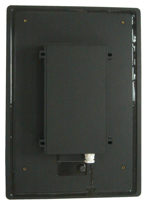
11 IV. Mechanic 1. Antenna overview: Assembling: 4 points of fixing, around the electronic case, diam 6 mm pour screw TF (not provided). STId 2010 NI1023A04 06/07/2010 P. 11 / 13
12 2. Reader overview Antenne Antenna Fixation de la plaque Protection avant avec plate cache fixation vis Wall Wall fixation Fixation fiwation murale - 3 points Plaque Protection Protection avant de plate propreté plate Coffret Electronique Top of the electronic Top of the case Capot electronic de case coffret électronique LED Fixation de la plaque avant avec cache vis Led Wall Mur / Support Wall / mounting support STId 2010 NI1023A04 06/07/2010 P. 12 / 13
13 V. Reader installation examples NO YES Ground loop Ground loop STId 2010 NI1023A04 06/07/2010 P. 13 / 13
mifare ID Reader with Selectable Outputs Data Sheet
 714-60 mifare ID Reader with Selectable Outputs Data Sheet Overview The 714-60 OEM proximity reader consists of three parts: a potted unit containing the electronics and antenna, a front cover, and an
Amano (itrt) Intelligent Twin Reader Terminal INSTALLATION MANUAL
 Intelligent Twin Reader Terminal INSTALLATION MANUAL") MODEL NUMBER: XRT910-0-0-AC-XX XRT920-0-0-AC-XX AMANO itrt Amano (itrt) Intelligent Twin Reader Terminal INSTALLATION MANUAL SPECIFICATIONS Working Environment Plastic Housing... Power Designed to work
MODEL NUMBER: XRT910-0-0-AC-XX XRT920-0-0-AC-XX AMANO itrt Amano (itrt) Intelligent Twin Reader Terminal INSTALLATION MANUAL SPECIFICATIONS Working Environment Plastic Housing... Power Designed to work
Aceprox FSK Proximity Reader REV2 Data Sheet
 Aceprox 688-52 FSK Proximity Reader REV2 Data Sheet Overview The 688-52 OEM proximity reader consists of three parts: a potted unit containing the electronics, a front cover, and an optional spacer plate.
MS-7000: SuperStar Reader
 The MS-7000 SuperStar Reader The MS-7000 SuperStar Reader is intended for installation in proximity applications where an extended read range is required. The reader provides an audio beeper and a multi
S125 Multi-Purpose 125 KHz RFID Reader USER MANUAL. 9V/24V DC Operating Voltage, AC (optional) KHz RFID EM4100/2 Cards & Tags
 KHz RFID EM4100/2 Cards & Tags") S125 Multi-Purpose 125 KHz RFID Reader 44 mm USER MANUAL MULTI PURPOSE 84 mm ONLINE & OFFLINE MODE BUILT-IN RELAY 125 KHz RFID EM4100/2 Cards & Tags 9V/24V DC Operating Voltage, AC (optional) 3 Online
S125 Multi-Purpose 125 KHz RFID Reader 44 mm USER MANUAL MULTI PURPOSE 84 mm ONLINE & OFFLINE MODE BUILT-IN RELAY 125 KHz RFID EM4100/2 Cards & Tags 9V/24V DC Operating Voltage, AC (optional) 3 Online
Mifare ID Reader. with selectable outputs
 714-52 Mifare ID Reader with selectable outputs The 714-52 OEM proximity reader consists of three parts: a potted unit containing the electronics and antenna, a front cover, and an optional spacer plate.
Temp-485-Pt100. A temperature sensor (Pt100 or Pt1000) communicating over the RS-485 bus with a simple communication protocol
 communicating over the RS-485 bus with a simple communication protocol") Temp-485-Pt100 A temperature sensor (Pt100 or Pt1000) communicating over the RS-485 bus with a simple communication protocol Temp-485-Pt100 Box version [600 113] Temp-485-Pt100 Cable version [600 114]
Temp-485-Pt100 A temperature sensor (Pt100 or Pt1000) communicating over the RS-485 bus with a simple communication protocol Temp-485-Pt100 Box version [600 113] Temp-485-Pt100 Cable version [600 114]
MS-5000: MiniStar Reader
 The MS-5000 MiniStar Reader The MS-5000 MiniStar Reader is intended for installation in a single gang electrical "J-Box," in proximity applications where an unobtrusive reader is required. It can also
Two Door Controller GEN-045
 Australian Owned, Designed and Manufactured Two Door Controller GEN-045 Genesis Electronics Australia Pty Ltd www.genesiselectronics.com.au Distributed by: Genesis reserves the right to change or modify
MS-5000 MiniStar Reader. Quick Start Guide MS The MS-5000 MiniStar Reader. 1.0 Specifications
 The MiniStar Reader The MiniStar Reader is intended for installation in a single gang electrical "J-Box," in proximity applications where an unobtrusive reader is required. It can also be mounted directly
DCC-8 DIGITAL TO EIGHT CURRENT LOOP CONVERTER OPERATING MANUAL
 DCC-8 DIGITAL TO EIGHT CURRENT LOOP CONVERTER OPERATING MANUAL 1 TABLE OF CONTENTS 1. MOUNTING INSTRUCTIONS 1.1 Standard DIN Rail mounting 1.2 Screw Mounting 2. FUSE REPLACEMENT 3. ASSEMBLING THE UNIT
SCB-C08 USB to RS232/422/485 Converter
 SCB-C08 USB to RS232/422/485 Converter USB Interface RS-232 signal RS-422 signal: RS-485 signal: Cable Type Transmission distance Signal LED Direct power from USB port Power consumption: Compliant with
INSTALLATION MANUAL. LC 200 Electronic Overload Guard. Software versione PW0501 R 0.3
 INSTALLATION MANUAL LC 200 Electronic Overload Guard Software versione PW0501 R 0.3 CONTENTS MAIN FEATURES LC 200 TECHNICAL FEATURES Page 2 SYMBOLS Page 3 WARNINGS Page 3 IDENTIFICATION DATA PLATE Page
MS-3000 MicroStar Reader
 MicroStar Reader The MicroStar Reader The MicroStar Reader is intended for installation on a window mullion or a door frame, on or off metal, in proximity applications where an unobtrusive reader is required.
MODEL: GR8-EM. Communication Adaptor GR8 Series
 Communication Adaptor GR8 Series Ethernet/RS-485 Adaptor (Modbus use) Functions & Features Bidirectional protocol converter for Modbus/TCP (Ethernet) and Modbus RTU (RS-485) Fast response time thanks to
MICRO-1356 MULTI-PROTOCOL READER
 MICRO-1356 MULTI-PROTOCOL READER Unique Features: The datasheet for the Micro-1356- USB and Micro-1356 readers are the same. The Micro-1356-USB reader is a USB version of the Micro-1356 embedded RFID reader
Installation manual Card reader Sirius i80(p) o Product o Installation o Connection o Technical data
 o Product o Installation o Connection o Technical data") Installation manual Card reader Sirius i80(p) o Product o Installation o Connection o Technical data Publication January 2014, Keyprocessor BV Paasheuvelweg 20 1105BJ Amsterdam, The Netherlands www.keyprocessor.com
Installation manual Card reader Sirius i80(p) o Product o Installation o Connection o Technical data Publication January 2014, Keyprocessor BV Paasheuvelweg 20 1105BJ Amsterdam, The Netherlands www.keyprocessor.com
REX F-0-9 Standalone or Access Controller
 REX F-0-9 Standalone or Access Controller Power supply The controller need s external power supply to operate. The Spider W40 power supply is sufficient to power two controllers and two 12V electric strikes
Fixed mount CCD bar code reader NFT Specification Ver. 1.0
 Fixed mount CCD bar code reader NFT-2100 Specification Ver. 1.0 Version Control number : Model : SS05011 NFT-2100 Version Date Revisions Description Ver 1.0 2005/06/09 - First registration 1. About this
SDM-6RO. Expansion Module 6 relay outputs. Manufactured for
 Version 1.0 5.02.2014 Manufactured for Thank you for choosing our product. This manual will help you with proper support and proper operation of the device. The information contained in this manual have
Quick Start Installation Guide
 apc/l Quick Start Installation Guide Version A2 Document Part Number UM-201 May 2010 OVERVIEW The apc/l is an intelligent access control and alarm monitoring control panel which serves as a basic building
EX-RC1 Remote I/O Adapter
 EX-RC1 Remote I/O Adapter The EX-RC1 interfaces between Unitronics Vision OPLCs and remote I/O Expansion Modules distributed throughout your system. The adapter is connected to a PLC via CANbus. Each adapter
MODEL: R1M-P4. PC Recorders R1M Series. SPECIFICATIONS OF OPTION: Q COATING (For the detail, refer to M-System's web site.)
") PC Recorders Series PC RECORDER (4 totalized counter inputs, 8 contact inputs and outputs) Functions & Features Industrial recorder on PC Totalized counter inputs Counts stored in E 2 PROM Easy system
PC Recorders Series PC RECORDER (4 totalized counter inputs, 8 contact inputs and outputs) Functions & Features Industrial recorder on PC Totalized counter inputs Counts stored in E 2 PROM Easy system
EX-RC1 Remote I/O Adapter
 EX-RC1 Remote I/O Adapter The EX-RC1 interfaces between Unitronics Vision OPLCs and remote I/O Expansion Modules distributed throughout your system. The adapter is connected to a PLC via CANbus. Each adapter
NS1 Connection Unit Guide
 PURPOSE AND APPLICATION Connection Unit Guide The connection unit is an installation friendly device, which makes it possible to use all features from a central unit. The CU can also be used to connect
OEM Proximity Reader with Keypad Manual REV1
 484-52 OEM Proximity Reader with Keypad Manual REV1 Overview The 484-52 proximity keypad reader provides pin code identification to be used together with a proximity identification card. The 484-52 consists
SP1 MP1 WP2 WP1. 125kHz reader models with the following prefixes: 13.56MHz reader models with the following prefixes:
 DOC0067 Issue 1.2 Reader Wiring InSTRUCTIONS SP1 MP1 WP2 WP1 125kHz reader models with the following prefixes: 13.56MHz reader models with the following prefixes: MP1-EM1 MP1-HT1 MP1-DP1 WP1-EM1 WP1-HT1
8-Port IP40 IEEE802.3af PoE Unmanaged Industrial Switch User s Manual
 8-Port IP40 IEEE802.3af PoE Unmanaged Industrial Switch User s Manual Version 1.1 Content Overview... 1 Introduction... 1 Features... 2 Technical Specifications... 3 Packing List... 5 Safety Precaution...
EXTENDER ELE8081. INSTALLATION Manual. Made in Taiwan
 EXTENDER ELE8081 INSTALLATION Manual Made in Taiwan Safety and Notice The ELE8081 HDMI EXTENDER has been tested for conformance to safety regulations and requirements, and has been certified for international
genesis TECHNICAL MANUAL Two-Door Controller GEN-045
 Two-Door Controller GEN-045 Genesis Electronics Australia Pty Ltd www.genesiselectronics.com.au info@genesiselectronics.com.au Australian Owned, Designed and Manufactured Distributed By:- Genesis reserves
ImproX IXP20 Controller INSTALLATION MANUAL
 MODEL NUMBER: ISC920-0-0-GB-XX ISC921-5-0-GB-XX IXP20 CONTROLLER SPECIFICATIONS Working Environment Plastic Housing... Power ImproX IXP20 Controller INSTALLATION MANUAL Designed to work in an indoor (dry)
MODEL: R1M-A1. PC Recorders R1M Series. SPECIFICATIONS OF OPTION: Q COATING (For the detail, refer to M-System's web site.)
") PC Recorders R1M Series PC RECORDER (contact input, 32 points) Functions & Features Industrial recorder on PC 32-point dry contact inputs Easy system expansion via Modbus RTU Recorded data exportable to
PC Recorders R1M Series PC RECORDER (contact input, 32 points) Functions & Features Industrial recorder on PC 32-point dry contact inputs Easy system expansion via Modbus RTU Recorded data exportable to
4 10/100/1000T Mini-GBIC with 4 IEEE 802.3at High Power PoE Industrial Wide Temperature Switch. User Manual SISTP LRT
 4 10/100/1000T + 2 1000 Mini-GBIC with 4 IEEE 802.3at High Power PoE Industrial Wide Temperature Switch User Manual V1.0 September-2013 FCC Warning This Equipment has been tested and found to comply with
MICRO-1356 MULTI-PROTOCOL READER
 MICRO-1356 MULTI-PROTOCOL READER The Micro-1356 reader is a miniature multi-protocol RFID reader suited for embedded applications, such as handheld readers or door key card readers. The Micro-1356 has
UC-2000 Installation Manual Unicorn Computers Technology Limited
 UC2000 Installation Manual Copyright 2003. All rights reserved. Table of Contents Specifications 2 Enclosure for the UC2000 Controller 3 Unicorn Access Control System Configuration 4 UC2000 Controller
Model: EP.L3800. Wiring Guide EP.L3800. Version 1.03 Last Updated:
 Wiring Guide EP.L3800 Version 1.03 Last Updated: 13-10-2014 1 Note: L3800 is the serial enabled lift controller. L3800 will ship with a HIO board in a package which can cater up to 8 floors. It can connect
Lantech. IPES /100TX with 4 PoE Injectors 24~48VDC Industrial Switch. User Manual
 Lantech IPES-0008-4 8 10/100TX with 4 PoE Injectors 24~48VDC Industrial Switch User Manual V1.00 Jun 2010 FCC Warning This Equipment has been tested and found to comply with the limits for a Class-A digital
SDM-8AO. Expansion Module 8 analog outputs. Manufactured for
 Version 1.0 16.05.2014 Manufactured for Thank you for choosing our product. This manual will help you with proper support and proper operation of the device. The information contained in this manual have
Manual 601: : USB/RS232. Specifications. Contents. Options
 Page 1 ATE-601 601: : USB/RS232 I/O Controller - 8 Inputs, 4/8 Relays The ATE-500/600 series is a range of modular I/O controllers. It uses small standardized boards which allows you to configure the system
Adapter Kit - QSI Electronics to G-Series Meter Installation Instructions
 Adapter Kit - QSI Electronics to G-Series Meter Installation Instructions These installation instructions cover the adapter kit installation of the QSI1, QSI2 and QSI3 versions of communications electronics
BIOC3 V1 USER S MANUAL. Biometric Reader v. b1
 BIOC3 V1 EN Biometric Reader USER S MANUAL v. b1 www.xprgroup.com 1 Contents 1. DESCRIPTION 2. SPECIFICATIONS 3. MOUNTING 4. WIRING 5. CONNECTING BIOMETRIC READERS TO EWS CONTROLLER 5.1 CONNECTING BIOMETRIC
It is the installer's responsibility to follow all instructions in this manual and to follow correct electrical practice.
 MCD Modbus Module Instructions Important User Information INSTALLATION INSTRUCTIONS: MCD MODBUS MODULE Order Code: 175G9000 1. Important User Information Observe all necessary safety precautions when controlling
Data sheet GCM MOD GMM EC.1 Communications module Modbus for GMM EC
 Data sheet GCM MOD GMM EC.1 Communications module Modbus for GMM EC ERP no.: 5206415 GCM MOD GMM EC.1 www.guentner.de Page 2 / 15 Contents 1 GCM MOD GMM EC.1...3 1.1 Functional description...3 1.2 Connections...
F1000 User's Manual. (Version: V1.01)
") (Version: V1.01) Contents Chapter 1 Overview... 2 Chapter 2 Installation... 3 2.1 Installation guide... 3 2.1.1 Installation position... 3 2.1.2 NEMA4 standard installation... 3 2.1.3 Environment precautions...
(Version: V1.01) Contents Chapter 1 Overview... 2 Chapter 2 Installation... 3 2.1 Installation guide... 3 2.1.1 Installation position... 3 2.1.2 NEMA4 standard installation... 3 2.1.3 Environment precautions...
Cluster Controller. Impro (CCM) Cluster Controller Module INSTALLATION MANUAL
 Cluster Controller Module INSTALLATION MANUAL") roxyb00t5 MODEL NUMBERS: HCM720-0-0-NN-XX HCM721-0-0-NN-XX HCM722-0-0-NN-XX HCM723-0-0-NN-XX HCM724-0-0-NN-XX HCM726-0-0-NN-XX Cluster Controller SPECIFICATIONS Impro (CCM) Cluster Controller Module INSTALLATION
roxyb00t5 MODEL NUMBERS: HCM720-0-0-NN-XX HCM721-0-0-NN-XX HCM722-0-0-NN-XX HCM723-0-0-NN-XX HCM724-0-0-NN-XX HCM726-0-0-NN-XX Cluster Controller SPECIFICATIONS Impro (CCM) Cluster Controller Module INSTALLATION
EX-RC1 Remote I/O Adapter
 EX-RC1 Remote I/O Adapter The EX-RC1 interfaces between Unitronics Vision OPLCs and remote I/O Expansion Modules distributed throughout your system. The adapter is connected to a PLC via CANbus. Each adapter
Adapter Kit - QSI Electronics to G2 Meter Installation Instructions
 Adapter Kit - QSI Electronics to G2 Meter Installation Instructions These installation instructions cover the adapter kit installation of the QSI1, QSI2 and QSI3 versions of communications electronics
MODEL: R1M-D1. PC Recorders R1M Series. SPECIFICATIONS OF OPTION: Q COATING (For the detail, refer to M-System's web site.)
") PC Recorders R1M Series PC RECORDER (contact output, 32 points) Functions & Features Industrial recorder on PC 32-point open collector outputs Easy system expansion via Modbus RTU Recorded data exportable
PC Recorders R1M Series PC RECORDER (contact output, 32 points) Functions & Features Industrial recorder on PC 32-point open collector outputs Easy system expansion via Modbus RTU Recorded data exportable
Installation manual Card reader Sirius i80l(p) o Product o Installation o Connection o Technical data
 o Product o Installation o Connection o Technical data") Installation manual Card reader Sirius i80l(p) o Product o Installation o Connection o Technical data Publication January 2014, Keyprocessor BV Paasheuvelweg 20 1105BJ Amsterdam, The Netherlands www.keyprocessor.com
Installation manual Card reader Sirius i80l(p) o Product o Installation o Connection o Technical data Publication January 2014, Keyprocessor BV Paasheuvelweg 20 1105BJ Amsterdam, The Netherlands www.keyprocessor.com
HD 2013 HD 2013-D AA-26 AA-27
 AA-26 HD 2013 HD 2013-D HD2013 TIPPING BUCKET RAIN GAUGE HD2013-D DATALOGGER TO MEASURE RAINFALL HD2013 BUCKET RAIN GAUGE Introduction The HD2013 is a reliable and sturdy bucket rain gauge, built entirely
RN-134. WiFly GSX Super Module SuRF Board. Features. Description. Applications. ~ page 1 ~ rn-134-ds v1.
 WiFly GSX Super Module SuRF Board Features UART interface with RS232 and TTL signaling Through hole board simplifies system integration Accepts 3-12VDC Status LEDs to show network status and data transfer
RS485 MODBUS Module 6RO
 Version 2.0 12/02/2013 Manufactured for Thank you for choosing our product. This manual will help you with proper support and proper operation of the device. The information contained in this manual have
Vorne Industries. Model 77/232 Serial Input Numeric 3" Display User's Manual
 Vorne Industries Model 77/232 Serial Input Numeric 3" Display User's Manual 1445 Industrial Drive Itasca, IL 60143-1849 (630) 875-3600 Telefax (630) 875-3609 Page 2 Model 77/232 Serial Input Numeric 3"
ADAM-4510 RS-422/RS-485 Repeater ADAM-4510S Isolated RS-422/485 Repeater ADAM-4520 Isolated RS-422/485 Converter Startup Manual
 ADAM-510 RS-/RS-85 Repeater ADAM-510S Isolated RS-/85 Repeater ADAM-50 Isolated RS-/85 Converter Startup Manual Packing List Before you begin installing your module, please make sure that the following
Connecting a Cisco Input Module
 CHAPTER 4 Overview The optional Cisco Input Module (Figure 4-1) is attached to a Cisco Physical Access Gateway or Cisco Reader Module to provide additional connections for up to ten input devices. Each
RS485 MODBUS Module 8AO
 Version 1.3 12/02/2013 Manufactured for Thank you for choosing our product. This manual will help you with proper support and proper operation of the device. The information contained in this manual have
Amano Nexus Lite Controller INSTALLATION MANUAL
 SPECIFICATIONS Working Environment Plastic Housing... Power NEXUS LITE Amano Nexus Lite Controller INSTALLATION MANUAL MODEL NUMBER: ISC920-0-0-AC-XX ISC921-5-0-AC-XX Designed to work in an indoor (dry)
Saturn Reader User Manual
 FCC Compliance Saturn Reader User Manual Version 1.00 On Track Innovations Ltd. (O T I) P/N 1100054F P/N 1100054F page 0 FCC Compliance FCC Compliance This device (Reader Saturn 3000) complies with Part
RC1170-RC232 USER MANUAL
 RC1170-RC232 USER MANUAL Overview: Introducing RC11XX-RC232 RF Transceiver boards for the data transmission using RF. Where RC11xx transceiver modules are compact surface-mounted high performance modules
isma-b-mg-ip User Manual Global Control 5 Sp. z o.o. Poland, Warsaw
 isma-b-mg-ip User Manual Global Control 5 Sp. z o.o. Poland, Warsaw www.gc5.pl Table of content 1 Introduction... 4 1.1 Revision history... 5 1.2 Safety rules... 5 1.3 Technical specifications... 6 1.4
ADDJOG User Guide 7/30/10. Overview
 ADDJOG User Guide 7/30/10 Overview The ADDJOG is a PLC expansion board used to add digital inputs and outputs to a compatible host PLC. The ADDJOG has 64 open collector outputs and 64 non-isolated inputs.
CONFIGURATION: The Reader, LED Indicator, pin numbers for the 9-pin connector and the 25-pin adapter are shown in Figure 1-2.
 FEATURES: Major features of the Swipe Reader are as follows: Powered through the USB port no external power supply required Hardware Compatible with PC or any computer or terminal with an RS-232 interface
HASP Student Payload Interface Manual
 HASP Student Payload Interface Manual Version 02.08.08 1 I. Introduction This document describes the basic features of your HASP payload mounting plate and provides information on the mechanical, electrical,
Xpass S2. Installation Guide. Intelligent IP Access Control Reader EN XPS2 V1.11.
 Intelligent IP Access Control Reader Installation Guide EN 101.00.XPS2 V1.11 www.supremainc.com Important Safety Information Carefully review the information within the user manual before installing or
Adapter Kit - QSI Electronics to TM Meter Installation Instructions
 Adapter Kit - QSI Electronics to TM Meter Installation Instructions These installation instructions cover the adapter kit installation of the QSI1, QSI2 and QSI3 versions of communications electronics
Indala Reader Installation Guide
 Indala Reader Installation Guide FCC This device complies with part 15 of the FCC rules. Operation is subject to the following two conditions: (1) this device may not cause harmful interference, and (2)
RS 485 Mini Modbus 1AO
 RS 485 Mini Modbus 1AO Version 1.0 14/08/2014 Manufactured for Thank you for choosing our product. This manual will help you with proper support and proper operation of the device. The information contained
Carbon Monoxide Sensor - ModBus
 Introduction The CO Sensor uses an electrochemical sensor to monitor CO level in a range of 0 to 500 ppm and communicates via an RS-485 network configured for ModBus protocol. Before Installation Read
Transcendent Frequency Counter
 Transcendent Frequency Counter with blue 2 x 16 LCD display This manual will guide you how to assemble, test and operate this frequency counter KIT. Features: The transcendent counter has two input channels
Message Runner KP3H. Text Display. Small messages on your machine. Compact DIN 36 x 72 profile. Green and orange character display.
 Message Runner KP3H Text Small messages on your machine This small and compact display is extremely well-suited for indicating a variety of short messages. Compact DIN 36 x 7 profile The compact DIN 36
RS485 MODBUS Module 8I8O
 Expansion Module 8 digital inputs, 8 digital outputs Version 2.2 12/01/2014 Manufactured for Thank you for choosing our product. This manual will help you with proper support and proper operation of the
Operation Manual. Thank you for selecting Keyking products. Please read this manual thoroughly before use. Models: TC418/419 Standalone Controller
 Operation Manual Thank you for selecting Keyking products. Please read this manual thoroughly before use. Models: TC418/419 Standalone Controller KEYKING GROUP Index Chapter 1: Summay...3 1.1 Outline...3
Product Data Sheet. BMS/Graphics Interface. Features
 BMS/Graphics Interface Product Data Sheet Features The Mxp-010 interface allows BMS systems and graphics PCs to be integrated with the Mx- 4000 series of Fire Control Panels and Remote Terminals. The interface
MODEL: R2K-1 SEN TRONIC AG. R2K Series
 1 MODEL: R2K-1 R2K Series /RS-485 CONVERTER Functions & Features Bidirectional converter between and RS-485 used when connecting Modbus RS-485 devices to a PC CE marking Standard: Conforms to, EIA Transmission
EA500. Installation Instructions Transponder
 EA500 EN Installation Instructions Transponder EA500 Installation Instructions 1.0 Overview EN 2 1.0 Overview The EA500 Transponder is the Security Escort module that provides communications between the
PROFIBUS-DP/MODBUS RTU REPEATER
 RP303 PROFIBUS-DP/MODBUS RTU REPEATER USER S MANUAL JAN/15 RP303 R P 3 0 3 M E smar www.smar.com Specifications and information are subject to change without notice. Up-to-date address information is available
Hypercable injecteur HPOE - Industrial IEEE 802.3at Gigabit PoE Injector. User Manual. v.1.0 Jun Mail :
 Industrial IEEE 802.3at Gigabit PoE Injector User Manual v.1.0 Jun-2011 FCC Warning This Equipment has been tested and found to comply with the limits for a Class A digital device, pursuant to Part 15
OWNER S MANUAL SINGLE CAT5E/6 3D EXTENDER B-320-1CAT-HDIR
 OWNER S MANUAL SINGLE CAT5E/6 3D EXTENDER B-320-1CAT-HDIR IMPORTANT SAFETY INSTRUCTIONS WARNING: To reduce the risk of fire or electric shock, do not expose this apparatus to rain or moisture. 1. Read
EXTENDER ELE8082. INSTALLATION Manual. Made in Taiwan
 EXTENDER ELE8082 INSTALLATION Manual Made in Taiwan Safety and Notice The ELE8082 HDMI EXTENDER has been tested for conformance to safety regulations and requirements, and has been certified for international
RN-174 WiFly Super Module
 RN- WiFly Super Module Features Evaluation board for the RN- module Supports chip antenna (RN--C), PCB trace antenna (RN--P), wire antenna (RN--W), and U.FL connector for an external antenna (RN--U) Ultra-low
Wiring Guide EP.NMINI. Version 1.02 Last Updated:
 Wiring Guide EP.NMINI Version 1.02 Last Updated: 14-10-2014 1 Note: See http://www.entrypass.net/ for updates, revisions, and download the latest installation manual There are currently 2 version of EntryPass
CRC220 and CRC221 INSTALLATION GUIDE. REF No.: DOC0014 ISSUE: 09
 CRC220 and CRC221 INSTALLATION GUIDE REF No.: DOC0014 ISSUE: 09 30th July 2015 2 Contents CRC220 & CRC221 INSTALLATION GUIDE 1. Scope 1-1 2. Introduction 2-1 2.1 Features 2-1 2.1.1. PCB Features 2-1 2.1.2.
Adapter Kit - Remote QSI Electronics Installation Instructions
 Adapter Kit Remote QSI Electronics Installation Instructions These installation instructions cover the adapter kit installation of the QSI1, QSI2 and QSI3 versions of communications electronics. The instructions
ICP DAS. ICP DAS 2015 M2M WLAN Wireless Solutions
 ICP DAS 2015 M2M WLAN Wireless Solutions Industrial Computer Industrial Product Data Computer Acquisition Product System Data Acquisition System PAC WLAN Wireless Solutions Wi-Fi Products WLAN Converter
CDN503 HIGH DENSITY I/O ADAPTER USER GUIDE
 CDN503 HIGH DENSITY I/O ADAPTER USER GUIDE 13050301 (c) Copyright DIP Inc., 1996 DIP Inc. P.O. Box 9550 MORENO VALLEY, CA 92303 714-924-1730 CONTENTS DN503 PRODUCT OVERVIEW 1 DN503 INSTALLATION 1 POWER
Serial Data DIN Fiber Link System
 USER GUIDE RLH Industries, Inc. The leader in rugged fiber optic technology. U-120 2017A-0420 DIN Fiber Link System COMPACT, RUGGED & TEMPERATURE HARDENED Introduction The DIN Fiber Link system transports
USB to RS-422/485 Serial Adapter
 USB to RS-422/485 Serial Adapter User Manual Ver. 4.00 All brand names and trademarks are properties of their respective owners. Contents: Chapter 1: Introduction... 3 1.1 Product Introduction... 3 1.2
Surface Resistivity Meter. Model SRM 232 MODE SELECT STORE SURFACE RESISTIVITY METER SRM-232 POWER. Operator s Guide
 Surface Resistivity Meter Model SRM 232 MODE SELECT STORE SURFACE RESISTIVITY METER SRM-232 POWER Operator s Guide 2971 Oxbow Circle Cocoa, FL 32926 1.0 System Overview The SRM-232 is a small hand-held
QRPometer Assembly Manual Copyright 2012 David Cripe NM0S The 4 State QRP Group. Introduction
 QRPometer Assembly Manual Copyright 2012 David Cripe NM0S The 4 State QRP Group Introduction Thank you for purchasing a QRPometer. We hope you will enjoy building it and and find it a useful addition to
1:N REDUNDANT SWITCHING UNIT REMOTE CONTROL TERMINAL
 MITEQ TECHNICAL NOTE 25T051 OCTOBER 2001 REV B 1.1 GENERAL DESCRIPTION 1.1.1 PHYSICAL 1:N REDUNDANT SWITCHING UNIT REMOTE CONTROL TERMINAL SECTION 1 INTRODUCTION Figure 1-1. Front Panel, 1:N Redundant
This Datasheet is for the IC693CBL300. I/O Bus Expansion Cables.
 This Datasheet is for the IC6CBL00 I/O Bus Expansion Cables http://www.qualitrol.com/shop/p-45-ic6cbl00.aspx Provides the wiring diagrams and installation guidelines for this GE Series 0-0 module. For
TCNM-ACBB1 Installation Manual
 The TCNM-ACBB1 is a connection box that can be used as an accessory to facilitate system connections for installation and device replacement of several Banner family reading devices. System cabling is
REV6 Multi Sector MIFARE Reader/Writer Data Sheet
 716-52 REV6 Multi Sector MIFARE Reader/Writer Data Sheet Overview The 716-52 REV6 multi sector MIFARE Reader/Writer is an intelligent 13.56MHz contactless reader writer designed to operate with the Mifare
SDM-8I8O. Expansion Module 8 digital inputs, 8 digital outputs. Manufactured for
 Version 1.2 20.01.2014 Manufactured for Thank you for choosing our product. This manual will help you with proper support and proper operation of the device. The information contained in this manual have
RS485 MODBUS Module 16I-M
 Version 2.0 12/02/2013 Manufactured for Thank you for choosing our product. This manual will help you with proper support and proper operation of the device. The information contained in this manual have
ICF-1150 Series Quick Installation Guide
 ICF-1150 Series Quick Installation Guide Second Edition, March 2012 2012 Moxa Inc. All rights reserved. P/N: 1802011500011 Overview Introduction The ICF-1150 series fiber converters are equipped with a
SERIE 59. Rear clamp. Frontal clamp HIGH RESOLUTION HOLLOW SHAFT INCREMENTAL ENCODER FOR INDUSTRIAL APPLICATIONS
 HIGH RESOLUTION HOLLOW SHAFT INCREMENTAL ENCODER FOR INDUSTRIAL APPLICATIONS Resolution up to 50.000 pulses per turn External diameter 58 mm Hollow shaft from Ø 10 to 14 mm Protection class IP67 according
Connecting a Cisco Output Module
 CHAPTER 5 Overview The optional Cisco Output Module (Figure 5-1) is attached to a Cisco Physical Access Gateway or Cisco Reader Module to provide additional connections for up to 8 outputs, each of which
HDMI (HDBaseT) Matrix Switcher Series Ed.B July 2013 Elpro Video Labs
 Matrix Switcher Series Ed.B July 2013 Elpro Video Labs") HDMI (HDBaseT) Matrix Switcher Series Ed.B July 2013 Elpro Video Labs ITEM NO.: 4 x 4 HDMI + HDBaseT Matrix Switcher With the latest and more affordable HDBaseT technology extend HDMI sources up to 100M
HDMI (HDBaseT) Matrix Switcher Series Ed.B July 2013 Elpro Video Labs ITEM NO.: 4 x 4 HDMI + HDBaseT Matrix Switcher With the latest and more affordable HDBaseT technology extend HDMI sources up to 100M
IEI emerge MicroNode Install and Setup Guide. Contents
 IEI emerge MicroNode Install and Setup Guide Contents Connecting power and the network to the MicroNode... 2 Using Power over Ethernet (PoE)... 3 or... 3 Using a 12 VDC power supply... 3 Connecting and