Concord LCD Keypad with 2-Way Voice Installation Sheet
|
|
|
- Nathaniel Barker
- 5 years ago
- Views:
Transcription


1 Concord LCD Keypad with 2-Way Voice Installation Sheet Description The Concord LCD Keypad with 2-Way Voice provides control of all programming and operation of compatible security systems. The 2-line, 16-character display provides easy to read messages to indicate the current status of the system. The keypad includes police, fire, and auxiliary panic buttons that can be activated anytime. An internal piezo provides system status beeps for trouble and alarm indications.* Two-way audio is achieved using an internal speaker and microphone combination.* A supervised hardwire zone provides an additional zone without added wiring to the panel. Opening the removable swing-down door reveals a label with basic system operating commands. * Not UL approved as a primary annunciator. Not investigated for use as two-way verification. Tools and Equipment needed 4-conductor, 18- or 22-gauge wire #2 Phillips screwdriver #6 screws and anchors (included) Screws for gang box installation Saw or utility knife for cutting wallboard Installation Installation Guidelines Mount the keypad in an environmentally controlled area (32 F to 120 F/0 C to 49 C). When mounting the keypad, allow at least 6 inches below it for the swing-down cover. When connecting two-way voice to the keypad, any additional speaker devices on the system should be connected in parallel with the keypad speaker connection. Note: Siren volume will be reduced if connected in series. This information differs from the information listed in the Concord 4 Installation Manual. Do not exceed the maximum available power given in the panel installation instructions. The hardwire zone is intended for use with intrusion sensors only. This zone input does not provide power for sensors such as PIRs, fire detectors, etc. Up to 16 keypads can be installed on a Concord 4 system of which a maximum of two can be connected to two-way audio or a single keypad plus an audio verification module. Table 1: Keypad Power Usage Current (ma) Conditions 110 Maximum alarm current with the buzzer sounding and the keypad illuminated from a button press 60 Typical operation 23 Power saving mode (no panel AC power) Table 2: Maximum SuperBus and Audio Wire Lengths Wire gauge (unshielded or shielded) feet feet Max. keypad wire length between keypad and panel Note: Interlogix recommends using shielded cable to prevent crosstalk between the speaker and microphone. Table 3: Maximum Hardwire Zone Wire Lengths Wire gauge (unshielded or shielded) feet Max. keypad zone wire length between keypad and sensor Hardwire zone End of Line (EOL) resistor should be 2K ohm. Installing the Mounting Plate 1. Place the keypad on a flat surface so that the mounting plate is facing as shown in Figure 1 on page Remove the mounting plate from the keypad as described in Figure 1 on page 2. P/N REV J 25OCT16 1 / 10

 from the panel and sensor to the keypad location. 3.")


 between keypad and hardwire sensor (if installed) 3.")
2 Figure 1: Removing Mounting Plate From Keypad To enable the tamper function: 1. Remove the two small flathead screws that attach the terminal block plate to the mounting plate. 2. Mount according to the process above. Note: Tamper screws must be installed into a stud. Wiring the Keypad CAUTION: Use static electricity precautions when handling electronic components. Utiliser les précautions de l'électricite statique lors de la manipulation des composants électroniques. 1. Remove the panel AC and backup battery power. 2. Run wires (18- or 22-gauge) from the panel and sensor to the keypad location. 3. Place the mounting plate on the wall and mark the primary and tamper mounting holes, making sure to leave a 6 inch clearance below the keypad for the door to open. See Figure 2 below. Note: Gang box mounting screws are not provided with this keypad. 4. Insert anchors into the wall at the marked locations where studs are not present. 5. Align the mounting plate over the selected mounting locations and secure the back plate using the screws provided. Note: Do not over tighten screws or the mounting plate may bind and prevent the keypad from mounting properly. Figure 2: Marking the Mounting Holes 4-conductor (no 2-way voice) between panel and keypad 8-conductor (with 2-way voice) between panel and keypad Note: Interlogix recommends using shielded cable to prevent crosstalk between the speaker and microphone. 2-conductor (to sensor) between keypad and hardwire sensor (if installed) 3. When routing the wires, route all wiring connections from the access area directly to the terminal, keeping wires short and flat. No loops of wire should run outside the access area. Note: Do not run any excess wire outside the access area as it will make the assembly of the keypad onto the mounting plate difficult. Wiring the Keypad SB Pull the ground, +12 volt and bus wires through the access area. 2. Connect the Bus to the 9 position terminal block as shown in Figure 3 below. Figure 3: Connecting the Keypad 6. Cut a hole in the wall at the wire access area of the mounting plate to pull the wiring cable through. Optional Tamper Mounting Note: Tamper mounting hardware is not supplied with this product. Note: For bus wire length over 150 feet, a 120 ohm termination resistor is needed across A to B at the panel. 2 / 10 Concord LCD Keypad with 2-Way Voice Installation Sheet

: Interlogix recommends using shielded cable to prevent crosstalk between the speaker and microphone. Note(2): The keypad is not UL approved as a primary annunciator.")
 Figure 6: Keypad to Audio Diagram (with Audio Verification Module) Wiring the Keypad Hardwire Zone 1.")
 resistor at the last device in the loop. See Figure 7 below. Note: The EOL resistor must be located at the last device in the loop. 4.")
3 Wiring the Keypad Speaker and Microphone 1. Pull the speaker and microphone wires through the access area. 2. Connect the speaker and microphone wires to the 9 position terminal block as shown in Figure 4 below, Figure 5 below and Figure 6 below. 3. If other audio devices will be installed on the system, wire accordingly as shown in the following diagrams. Note (1): Interlogix recommends using shielded cable to prevent crosstalk between the speaker and microphone. Note(2): The keypad is not UL approved as a primary annunciator. Note(3): Installations requiring an AVM in addition to the Keypad Audio require the addition of a 10 K ohm resistor (included) on the MIC wire of the AVM to equalize the MIC performance of both devices. Figure 4: Keypad to Audio Diagram (keypad only) Figure 6: Keypad to Audio Diagram (with Audio Verification Module) Wiring the Keypad Hardwire Zone 1. Pull the hardwire zone wires through the access area. 2. Connect the hardwire zone wires to the 9 position terminal block as shown in Figure 7 below. 3. Insert the end-of-line (EOL) resistor at the last device in the loop. See Figure 7 below. Note: The EOL resistor must be located at the last device in the loop. 4. Use a maximum of five contacts. Note: The keypad does not supply power for sensors. Sensor Zones must be of the normally open or closed contact type. Figure 7: Hardwire Zone Figure 5: Keypad to Audio Diagram (multiple speakers) Concord LCD Keypad with 2-Way Voice Installation Sheet 3 / 10


 Note: To remove, depress both latches")
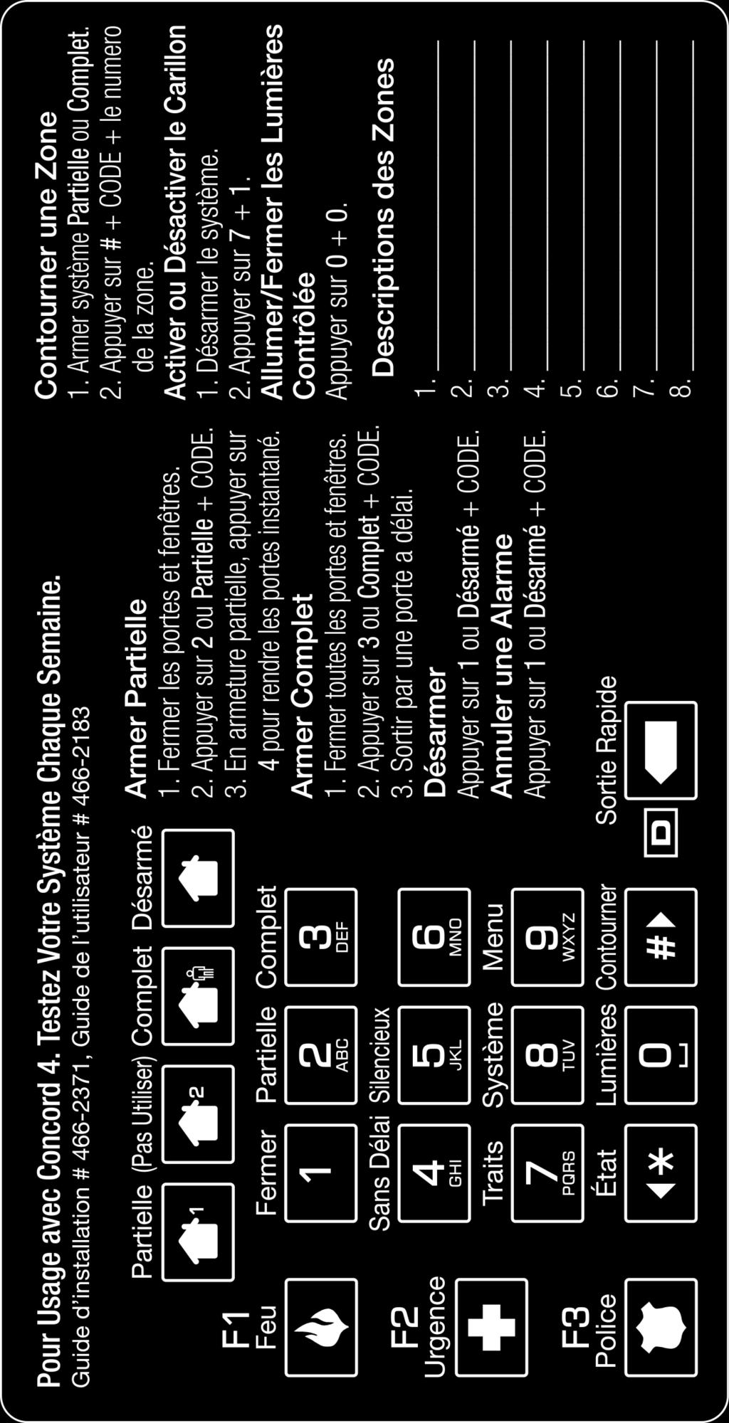
4 External Contact Wiring Figure 9: Function Key Decals Table 4: External switches Normally closed Short = Tamper 2K ohm = Normal Open = Alarm Normally open Open = Tamper Short = Alarm 2K ohm = Normal Note: A bus failure will result in a zone trouble condition. Attaching the Keypad to the Mounting Plate 1. Align the right side of the keypad over the hooks on the mounting plate. See Figure 8 below. 2. Swing the left side of the keypad over the latches on the mounting plate, until the latches snap into place. See Figure 8 below. Figure 8: Attaching the Keypad to the Mounting Plate Please refer to Table 5 below or to the specific panel installation/user manual for more information on when specific key presses are required. Note: The Auxiliary Alarm Key is not evaluated for and not to be used for UL 1637 (medical) applications. Table 5: Key Functions Key Function Scroll through available options at current menu tier Enter pauses when programming telephone numbers (no end user function) Note: To remove, depress both latches on the left side and then swing the left side of keypad away from the wall, removing the keypad from the hooks. Applying Decals A set of decals is included with the keypad for labeling the function keys. For Concord 4, the function keys are programmed: Fire (F1), Auxiliary (F2) and Police (F3). Carefully apply the function key decals (as needed) on the keypad as shown in Figure 9 below. Delete certain program settings Also used as Quick Exit key for end-user Power up and Bus Communication Follow the steps below for powering up the panel and for verifying that the keypad and the panel are properly communicating with each other. Note: Upon power up, the panel scans the bus for connected devices, assigns a unit number to each bus device, and automatically learns the device ID number of each bus device. 1. Verify that all wiring between the panel and keypad is correct. 2. Connect the panel battery and restore AC power. Alphanumeric keypads briefly show SCANNING BUS DEVICES, then displays date and time. Optional (steps 1 through 7) 1. At the keypad, enter program mode by pressing 8 + installer/dealer code (default = 4321) The keypad should display SYSTEM PROGRAMMING. 4 / 10 Concord LCD Keypad with 2-Way Voice Installation Sheet

5 2. Press. The display should show SECURITY. 3. Press or until the display shows ACCESSORY MODULES, then press. The display should show BUS DEVICES. 4. Press. The display shows the lowest device address and its ID. The following example shows what a device address display may look like: UNIT - ID * *The 8-digit SuperBus ID number is also located on a label on the back of the keypad. 5. Press or to cycle through all bus device addresses until the keypad appears. 6. After verifying the keypad device ID, press repeatedly until the display shows SYSTEM PROGRAMMING. 7. Press or until the display shows EXIT PROGRAMMING READY, then press. The keypad should show the date and time display. Programming To program options for the newly installed keypad (such as key beeps) see the specific panel Installation Instructions. Connecting the Keypad for System Programming Only For installations that don t include an alphanumeric keypad as a permanent part of the system, connect one for system programming to the Programming Keypad Header on the panel. To do this, first connect a Programming Keypad Cable (60-791) to the keypad wires. See the Programming Keypad Cable Installation Instructions (P/N ), included with the cable). Then, use the appropriate procedure for connecting the keypad. To connect a programming keypad to a Concord 4 panel: 1. With the panel powered up, connect the cable to the Programming Keypad Header Pins. See Figure 10 below. Figure 10: Connecting a Programming Keypad Concord 4 2. Activate the keypad by pressing + installer/dealer CODE Enter program mode by pressing + installer/dealer CODE + + and program the panel using the panel Installation Instructions. 4. When programming is completed, disconnect the programming keypad. Testing Note: Contact the central monitoring station before activating alarms to avoid dispatching local police and fire departments. Test the keypad by arming/disarming the system, activating the keypad panics, bypassing sensors, and by turning chime and lights on/off to verify correct operation. Refer to the panel User s Manual for complete system operating instructions. Adjusting Display Brightness The keypad display can be adjusted for easier viewing to help compensate for lighting conditions in the keypad location. The brightness adjustment lightens or darkens the background. To adjust display brightness: 1. Enter user programming mode by pressing 9 + user, partition, or system master CODE. The display shows SYSTEM MENU, then TIME AND DATE. 2. Press until the display shows OPTIONS, then press. The display should show DOWNLOADING ON/OFF (current setting). 3. Press twice. The display should show KEYPAD BRIGHTNESS 2 (default setting). 4. Enter a setting from 0 (darkest background) to 3 (brightest background), then press. 5. The display flashes the entered selection, then stops after pressing and displays the new setting and brightness level. Concord LCD Keypad with 2-Way Voice Installation Sheet 5 / 10
 Solid red (while backlights are on) Flashing red Flashing blue System status System is disarmed, status is normal System armed System is")
6 6. Exit user programming mode. Status LEDs The keypad has LEDs that indicate the current system status at a glance. Table 6 below explains LED behavior. Table 6: Status LEDs LED Solid blue (while backlights are on) Solid red (while backlights are on) Flashing red Flashing blue System status System is disarmed, status is normal System armed System is in alarm System is disarmed, trouble or alarm condition present (for example protest, low battery, supervisory, bus trouble, tamper, open zone, etc.) Note: Solid status LEDs display only when a key is pressed or backlighting is on. Flashing LEDs remain flashing until the fault or alarm condition is cleared. Door and Hinge Removal 1. Remove the keypad from the mounting plate. 2. Using a screwdriver, back out the hinge retainer screws 1/8. See Figure Remove the door and hinges. Note: Per SIA CP requirements, the door must remain attached and closed during normal operation. Figure 11: Door and Hinge Removal Troubleshooting Problem Keypad doesn t power up (no display and no beeps when keys are pressed). Keypad status blue LED is flashing and a trouble star is displayed on the LCD indicating a trouble condition and system doesn t respond to commands from keypad. No sound coming from speakers Specifications Action/Solution Compatibility Concord 4 Power requirements Current ma Current - 60 ma Current - 23 ma Operating temperature Storage temperature Humidity Check for correct wiring connections at keypad and panel terminals. Make sure panel battery is connected correctly and that the panel transformer is plugged in. Make sure panel transformer is not plugged into an electrical outlet controlled by a switch. Relocate transformer to an unswitched outlet location, if necessary. Check for correct bus wiring connections (green and white wires) at keypad and panel terminals. Check for correct wiring connections at keypad and panel terminals. 12 VDC nominal Maximum alarm current Typical operation Power saving mode (no panel AC power) 32 to 120 F (0 to 49 C) -4 to 140 F (-20 to 60 C) 95% relative, non-condensing Dimensions 5.32 x 6.03 x.092 (L x W x D) Regulatory Information Manufacturer UL listings UTC Fire & Security Americas Corporation, Inc Red Fox Rd., Arden Hills, MN , USA UL 985 Household Fire Warning System Units UL 1023 Household Burglar-Alarm System Units UL1610 Central Station Burglar-Alarm Units (Commercial Burglary) Note: See specific panel Installation Instructions for complete UL installation requirements. Not investigated by UL for use as a medical alert. 6 / 10 Concord LCD Keypad with 2-Way Voice Installation Sheet
7 FCC compliance FCC Part 15 Information to the User Changes or modifications not expressly approved by Interlogix can void the user s authority to operate the equipment. FCC Part 15 Class B This equipment has been tested and found to comply with the limits for a Class B digital device, pursuant to part 15 of the FCC Rules. These limits are designed to provide reasonable protection against interference in a residential installation. This equipment generates, uses, and can radiate radio frequency energy and, if not installed and used in accordance with the instructions, may cause harmful interference to radio communications. However, there is no guarantee that interference will not occur in a particular installation. If this equipment does cause harmful interference to radio or television reception, which can be determined by turning the equipment off and on, the user is encouraged to try to correct the interference by one or more of the following measures: Reorient or relocate the receiving antenna. Increase the separation between the equipment and receiver. Connect the affected equipment and the panel receiver to separate outlets, on different branch circuits. Consult the dealer or an experienced radio/tv technician for help. This Class B digital apparatus complies with Canadian ICES-003. Cet appareil numérique de la classe B est conforme à la norme NMB-003 du Canada. L utilisation de ce dispositif est autorisée seulement aux conditions suivantes : (1) il ne doit pasproduire de brouillage et (2) l utilisateur du dispositif doit être prêt à accepter tout brouillage radioélectrique reçu, même si ce brouillage est susceptible de compromettre le fonctionnement du dispositif. damages under any theory of liability, whether based in contract, tort, negligence, product liability, or otherwise. Because some jurisdictions do not allow the exclusion or limitation of liability for consequential or incidental damages the preceding limitation may not apply to you. In any event the total liability of Interlogix shall not exceed the purchase price of the product. The foregoing limitation will apply to the maximum extent permitted by applicable law, regardless of whether Interlogix has been advised of the possibility of such damages and regardless of whether any remedy fails of its essential purpose. Installation in accordance with this manual, applicable codes, and the instructions of the authority having jurisdiction is mandatory. While every precaution has been taken during the preparation of this manual to ensure the accuracy of its contents, Interlogix assumes no responsibility for errors or omissions. Contact Information For general information, see For customer/technical support, see or call United Technologies Corporation. Interlogix is part of UTC Building and Industrial Systems, a unit of United Technologies Corporation. All rights reserved. Limitation of Liability To the maximum extent permitted by applicable law, in no event will Interlogix be liable for any lost profits or business opportunities, loss of use, business interruption, loss of data, or any other indirect, special, incidental, or consequential Concord LCD Keypad with 2-Way Voice Installation Sheet 7 / 10
8 Installer: Please provide these pages to the end user. 8 / 10 Concord LCD Keypad with 2-Way Voice Installation Sheet
9 Concord LCD Keypad with 2-Way Voice Installation Sheet 9 / 10
10
ATP1000 Touchpad/Display Installation Instructions
 ATP1000 Touchpad/Display Installation Instructions Product summary The ATP1000 lets you control all programming and operation of compatible security systems (see the Specifications section). The large
Installation Instructions. Product Summary. Installation Guidelines. Tools and Equipment Needed. Table 1. Touchpad Power Usage
 Document Number: 466-1759 Rev. B August 2000 6 A I J 5 O I J A 9 A A O B B 0 A ) M = O )!, A = O 5 EA J 2 = C A H * " # $. A = J K H A I 5 O I J A A K + % & ' 5 J = J K I EC D J I * O F = I I, Installation
Installation Instructions Installation Guidelines. Product Summary. For the maximum number of bus devices and touchpads per panel see Table 1.
 Document Number: 466-1632 Rev. B September 2000 Product Summary The ITI SuperBus 2000 2 x 20 LCD (liquid crystal display) Alphanumeric Touchpad gives you complete on-site system programming and operation
SuperBus 2000 Phone Interface/Voice Module Installation Instructions
 SuperBus 2000 Module Installation Instructions Product summary The SuperBus 2000 (PIV) Module provides phone and voice functions for the Concord, Concord 4, and Concord Express (v4) panels. The PIV module
Advisor Sync Mobile Install & User Guide
 Advisor Sync Mobile Install & User Guide Version 5.5.7 or later EN English: Installation Guide Description Advisor is a family of life-safety protection and comfort management systems used to detect, control,
CWA BT320 Product Information Guide
 TM Printed in China Part No. 480-900-P Version A CWA BT320 Product Information Guide IMPORTANT To get the full capability of your new Cobra Airwave 360, please read this manual. It's more than just a Bluetooth
7760 LCD Glass Keypad
 * * * INSTALLATION GUIDE 7760 LCD Glass Keypad Description The DMP Model 7760 LCD Glass Keypad offers the same functionality and flexible features as standard DMP keypads. The contemporary glass touch
Installation Instructions
 Alliance Arming Station AL-1111, AL-1116 1048520C September 2006 Copyright 2006, GE Security Inc. Introduction This is the GE Alliance Arming Station for models AL-1111 (four-line LCD) and AL-1116 (four-line
R SERIES INSTALLATION GUIDE
 R SERIES INSTALLATION GUIDE Welcome to your smartest install yet. Things you should know Latch R is a proximity reader, keypad, and wireless entry system, that can be operated as a standalone device or
User guide. Bluetooth Music Receiver BM10
 User guide Bluetooth Music Receiver BM10 Contents Accessory overview...3 Basics...4 Pairing and connecting...5 Disconnecting and reconnecting...6 Smart Connect...7 Legal information...8 Declaration of
INSTUDIO BLUETOOTH SPEAKER BS1130TUS BS1130TE Instruction Manual
 INSTUDIO BLUETOOTH SPEAKER BS1130TUS BS1130TE 8016810 Instruction Manual A. INTRODUCTION This Bluetooth wireless speaker system applies the latest BT 2.1 wireless technology platform that enables you to
User guide. Bluetooth Keyboard BKB50
 User guide Bluetooth Keyboard BKB50 Contents Basics...3 General overview...3 Keyboard overview...3 Charging the keyboard...4 Turning on and off...5 Getting started...6 Setting up the keyboard...6 Assembly...6
H3-EM Electronic Swinghandle Operating Instructions
 H3-EM-66-100 Electronic Swinghandle Operating Instructions Package Contents H3-EM-66-x00 Electronic Swinghandle with RFID Reader (qty1) EM-0-45827 M3x25 POZIDRIV Mounting Screws (qty 4) EM-0-47151 M3x14
X1469.
 X1469 Please keep this instruction sheet for future reference, as it contains important information. Requires three AA batteries (included) for operation. Adult assembly is required for battery replacement.
2.5 SATA Drive Mobile Rack for 3.5 Bay - Anti-Vibration
 2.5 SATA Drive Mobile Rack for 3.5 Bay - Anti-Vibration SATBP125VP *actual product may vary from photos FR: Guide de l utilisateur - fr.startech.com DE: Bedienungsanleitung - de.startech.com ES: Guía del
Z-Wave Plus Smart Switch Dual Rocker. Installation Guide Ecolink Intelligent Technology Inc. PN DDLS2-ZWAVE5. A Universal Electronics Company
 Z-Wave Plus Smart Switch Dual Rocker A Universal Electronics Company Installation Guide Product Overview Easily automate overhead lights, table lamps or other accessories with the Ecolink Z-Wave Plus Smart
INSTALLATION AND SETUP GUIDE
 INSTALLATION AND SETUP GUIDE idevices SMART HOME SOLUTIONS 1 REQUIRES A compatible idevices product idevices Connected app Controlling this product requires an iphone, ipad or ipod touch that supports
User guide. Bluetooth Keyboard BKB10
 User guide Bluetooth Keyboard BKB10 Contents Basics...3 Overview... 3 Charging the keyboard... 4 Turning on the keyboard... 5 Getting started... 6 Setting up the keyboard... 6 Support on the web...6 Legal
Bluetooth Sound Bar with Built-in Subwoofer Model: SB210
 Bluetooth Sound Bar with Built-in Subwoofer Model: SB210 Package Contents Bluetooth Sound Bar with Built-in Subwoofer Remote control 2 AAA batteries Power adaptor Stereo 3.5mm audio cable Stereo RCA audio
Installation Instructions RF5010 and RF5210
 Installation Instructions RF5010 and RF5210 HES, Inc. 2260 N. 17th Ave. Phoenix, AZ 85027 800-626-7590 1 Product Description Dimensions Orientation Compatibility Access Control Systems Proximity Cards
7000 Series Thinline LCD Keypads Models 7060/7063/7070/7073
 INSTALLATION SHEET 7000 Series Thinline LCD Keypads Models 7060/7063/7070/7073 Description The DMP Model 7060, 7063, 7070, and 7073 Thinline LCD Keypads offer the same flexible features and functionality
Preparing Door. P/N AYRD-120-STANDALONE-INST-FUL Rev F
 Yale Real Living Key Free Touchscreen Deadbolt Installation and Programming Instructions Before you begin DOWNLOAD THE BILT APP for step-by-step installation instructions & to register your product x3
sher-price.com
 www.fisher-price.com Table of Contents Getting Started Introduction... 3 Tips for Better Images... 4 Features... 5 Specifi cations... 8 Setting Up Your Camera Battery Safety Information... 9 Battery Installation...10
GETTING STARTED. Cord clip. USB charge cable. Earbud tips. Inner ear hooks. Carry case. The following items are included
 U S E R G U I D E GETTING STARTED The following items are included Cord clip USB charge cable Earbud tips Inner ear hooks Carry case Product overview 1. Volume up / skip forward 2. LED indicator 3. Micro
INSTALLATION & SETUP GUIDE FOR SINGLE POLE & 3-WAY CONFIGURATIONS IN WALL SOLUTIONS
 INSTALLATION & SETUP GUIDE FOR SINGLE POLE & 3-WAY CONFIGURATIONS IN WALL SOLUTIONS 1 REQUIRES Wi-Fi 2.4 GHz 802.11 b/g/n compatible network Router Security Settings Supported: WPA, WPA2, or None Free
User guide. Stereo Bluetooth Headset SBH60
 User guide Stereo Bluetooth Headset SBH60 Contents Introduction...3 Function overview...3 Hardware overview... 3 Basics...5 Charging the battery...5 Turning the headset on and off...5 Adjusting the volume...
Dual-Bay Drive Enclosure for msata SSD Drives - USB 3.1 (10Gbps), USB-C - RAID
, USB-C - RAID") Dual-Bay Drive Enclosure for msata SSD Drives - USB 3.1 (10Gbps), USB-C - RAID SMS2BU31C3R *actual product may vary from photos FR: Guide de l utilisateur - fr.startech.com DE: Bedienungsanleitung - de.startech.com
Dual-Bay Drive Enclosure for msata SSD Drives - USB 3.1 (10Gbps), USB-C - RAID SMS2BU31C3R *actual product may vary from photos FR: Guide de l utilisateur - fr.startech.com DE: Bedienungsanleitung - de.startech.com
ShoreTel IP Phone 655. Quick Install Guide & Warranty
 ShoreTel IP Phone 655 Quick Install Guide & Warranty Document and Software Copyrights Copyright 1998-2012 by ShoreTel Inc., Sunnyvale, California, USA. All rights reserved. Printed in the United States
Installation Instructions RF5010 and RF5210
 Installation Instructions RF5010 and RF5210 HES, Inc. 22630 N. 17th Ave. Phoenix, AZ 85027 800-626-7590 1 Product Description Dimensions Orientation Compatibility Access Control Systems Proximity Cards
High-Resolution Audio Headset MDR-NC750
 User guide High-Resolution Audio Headset MDR-NC750 Contents Getting started...3 Introduction...3 Overview...3 Learning the basics...4 Wearing the headset...4 Connecting your headset to your device...4
Box Contents. 1. Balance Keyboard 2. Wireless Receiver 3. Two AAA Batteries. Balance Keyboard user manual
 User Guide Box Contents 2 3 1. Balance Keyboard 2. Wireless Receiver 3. Two AAA Batteries 1 /1 Step 1: Remove the back housing and insert AAA batteries. Remove Wireless Receiver from housing. Step 2: Plug
Bluetooth Enabled Access Control MODEL BG-FE. Operating Instructions
 BlueGuard FE Bluetooth Enabled Access Control MODEL BG-FE Operating Instructions CAUTION AND SAFETY INFORMATION IMPORTANT: If the equipment is used in a manner not specified in this manual, the protection
NUMBER SLIDE ERGONOMICS. Mini Keyboard with Retractable Number Pad
 NUMBER SLIDE Mini Keyboard with Retractable Number Pad ERGONOMICS x The Number Slide s retractable number pad slides out when you need it and away when you re finished. This feature delivers important
USB 3.1 Dual 3.5 in. SATA (6Gbps) HDD Enclosure with RAID S352BU313R
 HDD Enclosure with RAID S352BU313R") USB 3.1 Dual 3.5 in. SATA (6Gbps) HDD Enclosure with RAID S352BU313R FR: Guide de l utilisateur - fr.startech.com DE: Bedienungsanleitung - de.startech.com ES: Guía del usuario - es.startech.com NL: Gebruiksaanwijzing
USB 3.1 Dual 3.5 in. SATA (6Gbps) HDD Enclosure with RAID S352BU313R FR: Guide de l utilisateur - fr.startech.com DE: Bedienungsanleitung - de.startech.com ES: Guía del usuario - es.startech.com NL: Gebruiksaanwijzing
Additional Help & Info
 USER MANUAL Additional Help & Info If you need additional help or information, please go to REM-Fit.com for tips, info, support & tutorials. Register your product at REM-Fit.com/register ZEEQ is a registered
Operating and Storage Temperature 5 General Warnings 6. Extracting Data 8 WARRANTY AND LEGAL
 M E D I A M O D U L E M M - 0 1 M A K I N G V I R T U A L R E A L I T Y Index WARNINGS Operating and Storage Temperature 5 General Warnings 6 BASICS Extracting Data 8 WARRANTY AND LEGAL Warranty 10-12
KP7 Keypad Quick Install Guide
 KP7 Keypad Quick Install Guide English Thank you for including the KP7, 7 button keypad, as part of the user interface strategy for your customer. The KP7 has been designed to provide years of trouble
User Guide. USB/Ethernet Charging Cradle. Mobility Electronics, Inc Via Pasar, San Diego, CA 92126, USA
 USB/Ethernet Charging Cradle 9918 Via Pasar, San Diego, CA 92126, USA User Guide Phone: (858) 880-2225 Fax: (858) 530-2733 www.invisioncradles.com Copyright 2006. All rights reserved. The information in
SuperBus Hardwire Input Module (HIM) Document Number: Rev. C September 1998
 Document Number: Rev. C September 1998") SuperBus Hardwire Input Module (HIM) Document Number: 466-1033 Rev. C September 1998 SuperBus Hardwire Input Module for installing a magnetic reed switch* that can provide tamper protection when the switch
SuperBus Hardwire Input Module (HIM) Document Number: 466-1033 Rev. C September 1998 SuperBus Hardwire Input Module for installing a magnetic reed switch* that can provide tamper protection when the switch
Quick Start Installation Guide
 RM-iCLASS Series Quick Start Installation Guide Version C0 Document Part Number UM-208 June 2009 OVERVIEW The RM-iClass Quick Start Installation Guide provides a summary of installation and connection
4-Bay 3.5 SATA/SAS Mobile Rack for Bays - Trayless
 -Bay.5 SATA/SAS Mobile Rack for 5.5 Bays - Trayless HSBSATSASB *actual product may vary from photos FR: Guide de l utilisateur - fr.startech.com DE: Bedienungsanleitung - de.startech.com ES: Guía del usuario
INSTALLATION GUIDE 4- IN- ONE EMV L1 & L2 PIN PAD XPED- 8006L2-3CR, POE/USB/RS232
 INSTALLATION GUIDE 4- IN- ONE EMV L1 & L2 PIN PAD XPED- 8006L2-3CR, POE/USB/RS232 1. POWER ON THE 8006 PIN PAD There are three model of communication interface for xped- 8006L2-3CR: USB interface cable,
4-Port USB KVM Switch - DisplayPort - 4K 60Hz
 4-Port USB KVM Switch - DisplayPort - 4K 60Hz SV431DPUA2 *actual product may vary from photos FR: Guide de l utilisateur - fr.startech.com DE: Bedienungsanleitung - de.startech.com ES: Guía del usuario
USB 3.0 to M.2 NGFF SSD Enclosure with UASP
 USB 3.0 to M.2 NGFF SSD Enclosure with UASP SM2NGFFMBU33 *actual product may vary from photos FR: Guide de l utilisateur - fr.startech.com DE: Bedienungsanleitung - de.startech.com ES: Guía del usuario
Wireless Conference Microphone Bases. User Guide
 User Guide BC-100T BC-24T Ⅰ. Part Names. Fig. 1 3 Front Panel 4 4 BC-100T BC-24T 5 FREQUENCY 718.275MHz AF MUTE 5 6 7 8 9 6 7 10 TALK MUTE 10 TALK MUTE 11 11 BC-100T BC-24T Back Panel 1 2 1 2 BC-100T
Installation Guide DRAFTMF4100
 Installation Guide MF4100 This Class B digital apparatus complies with Canadian ICES-003 Cet appareill numérique de la classes B est conform à la norme NMB-003 du Canada This device complies with Part
HomePro ZRF113. Z-Wave Radio Frequency (RF) Controlled, 120 VAC, Isolated Contact Fixture Module, Series 200, Release 2.2
 Controlled, 120 VAC, Isolated Contact Fixture Module, Series 200, Release 2.2") RF Home Automation ZRF113 Z-Wave Radio Frequency (RF) Controlled, 120 VAC, Isolated Contact Fixture Module, Series 200, Release 2.2 Note: This module must be Included in the Network only where it will
RF Home Automation ZRF113 Z-Wave Radio Frequency (RF) Controlled, 120 VAC, Isolated Contact Fixture Module, Series 200, Release 2.2 Note: This module must be Included in the Network only where it will
56-A11A Plantronics Calisto Headset with Bluetooth USB Adapter. User Guide
 56-A11A-10511 Plantronics Calisto Headset with Bluetooth USB Adapter User Guide ii Table of Contents Package Contents... 1 Product Features... 2 Wearing The Headset... 3 Powering... 4 Charging... 4 Indicator
2GI. Touch Screen Wireless Keypad
 2GI Touch Screen Wireless Keypad For Remote Control of the 2GIG Security System INSTALL INSTRUCTIONS This document describes the basic installation information for the 2GIG TS1 and the steps necessary
Mini Speaker. CWA BT300 Product Information Guide
 Mini Speaker CWA BT300 Product Information Guide IMPORTANT To get the full capability of your new Cobra Airwave Mini, please read this manual. It's more than just a Bluetooth Speaker! Volume Down Micro-USB
> Mounting - Mount keypad and devices at the tested location. 6 Display shows RADIO RANGE TEST? Press YES, the
 Made by RSI VIDEO TECHNOLOGIES 1010-XMBIN February 2012 Product Summary The Indoor Keypad Model XMB611 is designed for use in configuring/programming and operating a Videofied TM security system. The keypad
WIRELESS BLUETOOTH BOOMBOX
 G-BOOM WIRELESS BLUETOOTH BOOMBOX Wireless Bluetooth Rugged Construction Rechargeable Battery USB Device Charging G-650 Welcome to G-PROJECT Thanks for purchasing G-BOOM and joining G-Project. With just
Hi! Let s get started. Streaming Stick
 Hi! Let s get started. Streaming Stick 1 Know your Streaming Stick 1 2 3 4 2 1 2 3 4 [HDMI CONNECTOR] Plugs into the HDMI port on the back of your TV [STATUS LIGHT] Indicates it is on when lit, or activity
Saitek WIRELESS ADAPTER
 Saitek WIRELESS ADAPTER USER MANUAL GETTING CONNECTED: IT S EASY! 1 2 3 4 5 6 Before you start, make sure that your Sony PlayStation 2 is turned OFF! Install the Receiver into the game console s ports
SySTIUM TECHNOLOGIES. Assembly Guide. Model 133i
 Assembly Guide Model 133i Radio Frequency Interference Notice (USA) This equipment has been tested and found to comply with the limits for a Class B digital device, pursuant to Part 15 of the FCC Rules,
MD-SPBT01 Bluetooth Speaker
 MD-SPBT01 Bluetooth Speaker Before using your new product, please read these instructions to prevent any damage. Modal MD-SPBT01 Bluetooth Speaker Contents Introduction... 2 Features... 3 Setting up your
Harris Bluetooth Remote Speaker Mic
 QUICK GUIDE 14221-1600-1010 May 2016 Harris Bluetooth Remote Speaker Mic 12082-0800-01 MANUAL REVISION HISTORY REV. DATE REASON FOR CHANGE - May/16 Initial release. CREDITS Harris and BeOn are registered
Installation Guide AVA-2902E/I. PCI-to-Fast SCSI Host Adapters. PCI SCSI Host Adapter with Internal or External Connector
 Installation Guide AVA-2902E/I PCI-to-Fast SCSI Host Adapters PCI SCSI Host Adapter with Internal or External Connector R 1 Installing the Host Adapter and SCSI Device WARNING: Before you start, turn OFF
Allworx Tx 92/24 Telephone Expander Installation Guide
 Allworx Tx 92/24 Telephone Expander Installation Guide No part of this publication may be reproduced, stored in a retrieval system, or transmitted, in any form or by any means, electronic, mechanical,
DOLL SHOULD NOT BE IMMERSED IN WATER.
 TM Please remove everything from the package and compare to the contents shown on page 2. If any items are missing, please call 1-888-892-6123. Keep these instructions for future reference as they contain
Yale Real Living Key Free Touchscreen Deadbolt Installation and Programming Instructions
 Yale Real Living Key Free Touchscreen Deadbolt Installation and Programming Instructions Optional Network Module x3 #8-32 x 5/16" Machine screws x4 #7 wood & #8-32 machine x 20mm Combination screws x2
ShrapnelQuick Guide. Quick Start, would like to show visually for first page: Power On Power Off Pairing Battery Life
 ShrapnelQuick Guide Quick Start, would like to show visually for first page: Power On Power Off Pairing Battery Life Shrapnel User Guide Technical Draft Main Speaker Controls Power On Long press and hold
USB 3.0 SATA/IDE 2.5 Hard Drive Enclosure
 USB 3.0 SATA/IDE 2.5 Hard Drive Enclosure UNI251BMU33 *actual product may vary from photos DE: Bedienungsanleitung - de.startech.com FR: Guide de l'utilisateur - fr.startech.com ES: Guía del usuario -
USB 3.0 SATA HDD/SSD Dock - 1:1 Duplicator SATDOCK2REU3
 USB 3.0 SATA HDD/SSD Dock - 1:1 Duplicator SATDOCK2REU3 *actual product may vary from photos FR: Guide de l utilisateur - fr.startech.com DE: Bedienungsanleitung - de.startech.com ES: Guía del usuario
WIFI REMOTE VIDEO DOORBELL MODEL: RL-IP02C USER MANUAL
 WIFI REMOTE VIDEO DOORBELL MODEL: RL-IP02C USER MANUAL Product Description CONTENTS Product Description...1 Features...1 Package Contents...1 Installation Instruction...2 Panel Introduction...2 Wiring
2.5 USB-C External Hard Drive Enclosure - Rugged - USB 3.1 (10Gbps)
") 2.5 USB-C External Hard Drive Enclosure - Rugged - USB 3.1 (10Gbps) S251BRU31C3 *actual product may vary from photos FR: Guide de l utilisateur - fr.startech.com DE: Bedienungsanleitung - de.startech.com
2.5 USB-C External Hard Drive Enclosure - Rugged - USB 3.1 (10Gbps) S251BRU31C3 *actual product may vary from photos FR: Guide de l utilisateur - fr.startech.com DE: Bedienungsanleitung - de.startech.com
SAFETY WARNINGS AND GUIDELINES
 1 SAFETY WARNINGS AND GUIDELINES Do not expose this device to water or moisture of any kind. Do not place drinks or other containers with moisture on or near the device. If moisture does get in or on the
Universal Charge & Sync Cabinet for Tablets/iPads - 10 Slot Charging Station with Lock and Fan
 Universal Charge & Sync Cabinet for Tablets/iPads - 10 Slot Charging Station with Lock and Fan ST10CSU2A * This page is an addendum to the warning label found on the product. The Warning Label (250V/5A)
Dual-Bay Drive Eraser, Duplicator, and Docking Station for 2.5 and 3.5 SATA
 Dual-Bay Drive Eraser, Duplicator, and Docking Station for 2.5 and 3.5 SATA SDOCK2ERU33 *actual product may vary from photos FR: Guide de l utilisateur - fr.startech.com DE: Bedienungsanleitung - de.startech.com
USB 3.1 (10Gbps) Standalone Duplicator Dock for 2.5 and 3.5 SATA Drives
 Standalone Duplicator Dock for 2.5 and 3.5 SATA Drives") USB 3.1 (10Gbps) Standalone Duplicator Dock for 2.5 and 3.5 SATA Drives SDOCK2U313R FR: Guide de l utilisateur - fr.startech.com DE: Bedienungsanleitung - de.startech.com ES: Guía del usuario - es.startech.com
USB 3.1 (10Gbps) Standalone Duplicator Dock for 2.5 and 3.5 SATA Drives SDOCK2U313R FR: Guide de l utilisateur - fr.startech.com DE: Bedienungsanleitung - de.startech.com ES: Guía del usuario - es.startech.com
Z-WavePlus Siren Installation Instructions
 Z-WavePlus Siren Installation Instructions Product Overview Z-Wave Plus enabled device which can be used to alert the user. Able to produce 4 different notification sounds Volume control located on the
C4DONGLE-3GNA-WBT INSTALLATION GUIDE
 C4DONGLE-3GNA-WBT INSTALLATION GUIDE V 1.0 07/08/2015 Table of contents Preface... 3 Warnings and notices... 3 1. Hardware features... 4 2. Hardware description... 5 2.1. External view... 5 2.2. Internal
REVOLABS Elite Wired Microphones
 REVOLABS Elite Wired Microphones Installation and Operation Guide Models: 01-EWM-DR-BLK 01-EWM-DR-WHT 01-EWM-DR-BNI 01-EWM-OM-BLK 01-EWM-OM-WHT 01-EWM-OM-BNI 2014 REVOLABS, INC. All rights reserved. No
Installation Instructions
 NX-148E-RF LCD Touchpad w/receiver 466-2198 Rev. B May 2005 Product summary The NX-148E-RF Touchpad w/receiver combines touchpad and receiver capabilities into a single device for use with NetworX NX-4,
Installation Quick Start Guide
 Installation Quick Start Guide For detailed information please refer to the full Agility 3 Installer Manual provided on our website: www.riscogroup.com Table of Contents 1. INSTALL THE MAIN UNIT... 3 2.
User guide. Stereo Bluetooth Headset SBH80
 User guide Stereo Bluetooth Headset SBH80 Contents Introduction...3 Function overview...3 Hardware overview... 3 Basics...5 Charging the battery...5 Battery status... 5 Turning the headset on and off...5
REACH YOUR SUMIT USER GUIDE
 REACH YOUR SUMIT USER GUIDE THANK YOU FOR PURCHASING YOUR ALPINERX AND BECOMING A MEMBER OF THE ALPINA COMMUNITY! PLEASE FOLLOW THE SIMPLE STEPS DETAILED IN THIS USER GUIDE TO START USING YOUR WATCH. 01.
iq 16 Sync Charge Box
 USER INSTRUCTIONS iq 16 Sync Charge Box (iq 16 SCB Sync Station ) www.lockncharge.com iq 16 Sync Charge Box Contents Overview...1 Specifications...1 Safety instructions...2 Set up...2 How to charge multiple
16-Port Serial Card PEX16S550LP
 16-Port Serial Card PEX16S550LP *actual product may vary from photos FR: Guide de l utilisateur - fr.startech.com DE: Bedienungsanleitung - de.startech.com ES: Guía del usuario - es.startech.com NL: Gebruiksaanwijzing
Blackboard MRD5 User Manual
 Blackboard MRD5 User Manual The Blackboard model MRD5, is a Mobile Reader Device for reading Blackboard mag-stripe and contactless cards. A card-swipe allows reading of mag-stripe cards and an internal
2009 VTECH Printed in China
 2009 VTECH Printed in China 91-002371-000-000 INTRODUCTION Welcome to the wonderful world of reading with the Bugsby Reading System! Bugsby is an adorable bookworm who will introduce your child to reading
INSTALLATION INSTRUCTIONS
 General Information INSTALLATION INSTRUCTIONS K3129-2V1 7/98 FA210RF Keypad/Transceiver The FA210RF Keypad/Transceiver is a combination unit. It replaces a FA210KP Fixed Addressable Keypad, 5881/5882M
FT2225 Satellite M2M Terminal. Quick Start Guide
 FT2225 Satellite M2M Terminal Quick Start Guide Distribution The information, specifications, and features contained in this document are subject to change without notice and should not be construed as
Plantronics Calisto II Headset with Bluetooth USB Adapter User Guide 56-K61A-23010
 56-K61A-23010 Plantronics Calisto II Headset with Bluetooth USB Adapter User Guide Contents Package Contents... 1 Product Features... 2 Wearing Your Headset... 3 Powering Your Headset and USB Bluetooth
ispd PRO Intelligent Sequential Power Distribution System
 ispd PRO Intelligent Sequential Power Distribution System Operating Manual www.peavey.com FCC/ICES Compliancy Statement This device complies with Part 15 of the FCC rules and Industry Canada license-exempt
Wireless Keyboard/Mouse/Dongle Users Manual
 Wireless Keyboard/Mouse/Dongle Users Manual Getting Started Thank you for choosing this 2.4G Wireless keyboard, Mouse and Dongle Kits. It operates with digital radio technology to ensure no hinder communication
SMARTPLUG. Quick Start Guide. Model: isp100. Intelligent Home Solutions. Control your SmartPlug from anywhere with your smartphone WHAT YOU LL NEED
 Model: isp100 Intelligent Home Solutions Quick Start Guide SMARTPLUG Control your SmartPlug from anywhere with your smartphone WHAT YOU LL NEED WiFi network transmitting at 2.4GHz 1 Apple device running
USB 3.0 Dual 2.5 SATA HDD/SSD RAID Enclosure
 USB 3.0 Dual 2.5 SATA HDD/SSD RAID Enclosure S252BU33R *actual product may vary from photos DE: Bedienungsanleitung - de.startech.com FR: Guide de l'utilisateur - fr.startech.com ES: Guía del usuario -
ZTE CORPORATION NO. 55, Hi-tech Road South, Shenzhen, P.R.China. MF833V USB Modem Quick Start Guide
 ZTE CORPORATION NO. 55, Hi-tech Road South, Shenzhen, P.R.China MF833V USB Modem Quick Start Guide LEGAL INFORMATION Copyright 2017 ZTE CORPORATION. All rights reserved. No part of this publication may
ipaq Networking 5 Port 10/100 Fast Ethernet Auto Sensing Switch
 ipaq Networking 5 Port 10/100 Fast Ethernet Auto Sensing Switch User and Setup Guide IPAQ NETWORKING 5 PORT 10/100 FAST ETHERNET AUTO SENSING SWITCH 1 Copyrights, Trademarks, and Disclaimer 2001 Compaq
Unity 100-watt Bridgeable Power Amp
 Unity 100-watt Bridgeable Power Amp P/N 18513 User's Manual CONTENTS SAFETY WARNINGS AND GUIDELINES... 3 INTRODUCTION... 4 FEATURES... 4 CUSTOMER SERVICE... 5 PACKAGE CONTENTS... 5 PRODUCT OVERVIEW...
FortiFone QuickStart Guide for FON-175
 FortiFone QuickStart Guide for FON-175 FortiFone QuickStart Guide for FON-175 Revision 1 May 24, 2016 Copyright 2016 Fortinet, Inc. All rights reserved. Fortinet, FortiGate, FortiCare and FortiGuard, and
Emergency Wall Communicator
 English SET UP INSTRUCTIONS Guardian Alert Emergency Wall Communicator Model #41920 This accessory is to be used with the LogicMark s CaretakerSentry product line. Up to 5 Two-way pendants and Emergency
EMPowered Motorized Touchscreen Keypad Deadbolt
 EMPowered Motorized Touchscreen Keypad Deadbolt What s in the box Battery Cover Interior Escutcheon Deadbolt Latch 2-3/4 Strike Plate Mounting Plate Deadbolt Latch 2-3/8 Security Plate AA x4 Batteries
Tric Flash Trigger TRIC-100 User s Manual
 Tric Flash Trigger TRIC-100 User s Manual 2017/7 rev. 1.4 1 Safety Statements FCC Class B Notice This device complies with Part 15 of the FCC Rules. Operation is subject to the following two conditions:
5-Port USB 3.1 (10Gbps) Combo Card - 1x USB-C, 2x USB-A + 2x IDC (5Gbps)
 Combo Card - 1x USB-C, 2x USB-A + 2x IDC (5Gbps)") 5-Port USB 3.1 (10Gbps) Combo Card - 1x USB-C, 2x USB-A + 2x IDC (5Gbps) PEXUSB312EIC *actual product may vary from photos FR: Guide de l utilisateur - fr.startech.com DE: Bedienungsanleitung - de.startech.com
5-Port USB 3.1 (10Gbps) Combo Card - 1x USB-C, 2x USB-A + 2x IDC (5Gbps) PEXUSB312EIC *actual product may vary from photos FR: Guide de l utilisateur - fr.startech.com DE: Bedienungsanleitung - de.startech.com
Bluetooth Stereo Headset
 Bluetooth Stereo Headset RF-BTHP01 User Guide Bluetooth Stereo Headset Contents Features... 3 Package contents... 3 Components... 4 Using your headset... 5 Charging the battery... 5 Turning your headset
Dual-Slot M.2 Drive to SATA Host Adapter for M.2 NGFF SSDs - RAID
 Dual-Slot M.2 Drive to SATA Host Adapter for M.2 NGFF SSDs - RAID S322M225R *actual product may vary from photos FR: Guide de l utilisateur - fr.startech.com DE: Bedienungsanleitung - de.startech.com ES:
EcoView 8 DO Module Installation and Commissioning
 Document No. 129-565 EcoView 8 DO Module Installation and Commissioning This document covers the installation and commissioning of the EcoView 8 DO Module. See the following documents for installation
IP Set-top Box (STB) Model No.: SP-110. Rev
 Model No.: SP-110. Rev") IP Set-top Box (STB) Model No.: SP-110 Rev. 1.0 2017.05 1 Contents Attentions... 3 SAFETY GUIDE... 3 SAFETY PRECAUTIONS... 3 SERVICING... 3 INSPECTION OF ALL ATTACHMENTS... 4 Preparation... 5 FRONT PANEL...
IP Set-top Box (STB) Model No.: SP-110 Rev. 1.0 2017.05 1 Contents Attentions... 3 SAFETY GUIDE... 3 SAFETY PRECAUTIONS... 3 SERVICING... 3 INSPECTION OF ALL ATTACHMENTS... 4 Preparation... 5 FRONT PANEL...