OptoLum Round Linear Light Strips
|
|
|
- Garey Lawrence
- 5 years ago
- Views:
Transcription
 Do not conceal or extend exposed conductors through a building wall. c) Do not install this system in wet locations.")
1 OptoLum Round Linear Light Strips BrightLine Round EcoLine HO, LO, SLO Round CaseLine Round FineLine HO, LO, SLO Round Important Safety Instructions a) Read all instructions. b) Do not conceal or extend exposed conductors through a building wall. c) Do not install this system in wet locations. d) To reduce the risk of fire and burns, do not install this lighting system where the exposed bare conductors can be shorted or contact any conductive material. e) To reduce the risk of fire and overheating, make sure all connections are tight. f) Do not install any luminaire closer than 6 inches (15.25cm) from any curtain, or similar combustible materials. g) Turn off electrical power before modifying the lighting system in any way. SAVE THESE INSTRUCTIONS GETTING STARTED OptoLum Round offers indoor cove lighting, display case lighting, and wall washing in a compact linear form. This guide contains important information on planning, installing, and operating your new Round Luminaire. For your protection, read it carefully and save it for future reference. INCLUDED IN THIS BOX 1 Round Luminaire with mounting clips. The clips have a predrilled hole to accommodate #6 screws for mounting and with mating power connector to attach to power supply. Part No. MTJ-LP GG-290; a Class 2-24VDC, 4.0A, 96W power supply with junction box and mating secondary power connector that matches to Round power connector and wire leads for connection to primary 120VAC. Installation Guide ADDITIONAL ITEMS NEEDED Mounting screws, screwdriver, drill SCOPE OF THIS USER GUIDE The goal of this user guide is to explain in an easily understandable language the necessary steps to install Round Luminaires and assure peak performance. Its intended use is for reference only, by persons who are fully qualified. This document should never be considered a substitute for any provision of a regulation or state and/or local code.
2 IDENTIFICATION AND WARNINGS OF SAFETY HAZARDS In accordance with ANSI Z the following system of identifying the severity of the hazards associated with the products is used: DANGER : Imminently hazardous situation which, if not avoided, will result in death or serious injury. WARNING : Potentially hazardous situation that, if not avoided, could result in death or serious injury. CAUTION : Potentially hazardous situation that, if not avoided, may result in minor or moderate injury or property damage. DANGER: Ensure that main power supply is off before installing or wiring Round Luminaries. Failure to adhere to these instructions will result in death or serious injury. DANGER: Round Luminaires must be installed by a qualified electrician in accordance with NEC and relevant local codes. Failure to comply will result in death, serious injury, or property damage. WARNING: Do not install or use Round Luminaires until you read and understand the installation instructions and safety labels. Failure to do so could result in serious injury or property damage. WARNING: Do not use Round Luminaires if the power cables are damaged. Doing so can result in death, serious injury, and property damage. CAUTION: Use appropriate materials and mounting methods to support the fixture adequately. Failure to do so can result in property damage and void the warranty CAUTION: Round Luminaires has no user serviceable parts. Do not attempt to service the fixture. Doing so will result in property damage and void the warranty. CAUTION: Do not use any other power supply other than the one specified and provided by OptoLum. Doing so will result in property damage and void the warranty. CAUTION: Do not exceed recommend length of Round Luminaires type per 96W power supply. Doing so will result in current overload. See table XX CAUTION: Do not use sharp tools near or on the fixtures electrical components. Doing so will result in property damage and void the warranty. CAUTION: Do not hot swap. Ensure that power to the fixture is off before connecting or disconnecting fixtures. Hot swapping will result in property damage and void the warranty. CAUTION: Round Luminaires are a Class 2 LED product with LED radiation. Do not stare into beam or view directly with optical instruments. CAUTION: For cabinet use only. To prevent the risk of fire, do not install a 12 section closer than 0.5 to a cabinet wall or in a compartment smaller than 13 by 13 by 13. NOTE: The instructions and precautions set forth in this user guide are not necessarily all-inclusive, all conceivable, or relevant to all applications as OptoLum cannot anticipate all conceivable or unique situations. OPERATING TEMPERATURE The Round Luminaire is designed with the latest LED technology to provide the maximum possible light output in a slim linear fixture. Although Round Luminaires operates at much cooler temperatures than traditional high illumination light fixtures, the housing can reach temperatures of 167º F (75C). For this reason, handle with care to prevent injuries and provide adequate ventilation to the fixture. During normal operation, the Round housing becomes very hot and remains hot for an extended time after operation is suspended. Exercise caution when handling the fixture after extended operation to prevent burns. It is necessary to provide adequate ventilation around the fixture. Adequate ventilation refers to the airflow over the surface of the fixture and air flow within the room, not the room temperature. A Round luminaire in a hot (40C) room with a fan or ventilation system that keeps air moving can actually run cooler on its surface than in a cool (20C) room with stagnant air. OWNER/USER RESPONSIBILITIES It is the responsibility of the contractor, installer, purchaser, owner, and user to install, maintain, and operate Round Luminaires in such a manner as to comply with all state and local laws, ordinances, regulations, and the American National Standard Institute Safety Code. PLAN THE INSTALLATION The nature and complexity of Round Luminaires installation requires in-depth planning to ensure timely, successful installation with minimal complications and down time.
3 PLANNING SUGGESTIONS When planning Round Luminaire installation, OptoLum suggests doing the following: Consult an Electrical Inspector to approve all wiring plans. Refer to local and state codes for installation compliance. Employ OptoLum Technical Support Services. INSTALLATION CONSIDERATIONS When creating your installation plan, consider the following: Zones: You create a zone by creating a layout of where the fixtures will be installer that will be designated to a power supply. All fixtures attached to that power supply reside within the designated zone. This will provide the check to make sure the length of luminaires does not exceed the recommended load on the supply. See TABLE A. For installations where groups of luminaires are controlled individually, set unique zones each with their own power supply. Location of power supply in relationship to luminaires: Each power supply is provided with an 11 foot lead, the lead supports up to a specific length See TABLE A for the maximum length of your type of Round luminaire to 96 Watt power supply. If the distance to Power supply is longer than 11 feet See TABLE B for lengths in excess of 11 feet for the appropriate wire gauge to support the distance to avoid voltage drop. Voltage drop will cause damage to the luminaire. Location of the fixture and method of attaching: Fixture locations need to be determined to mark locations of the mounting spring clip locations. When the location has been determined the whole location in the base of the clip should be marked to indicate predrilling locations for screw installation. Round luminaires are supplied with spring clips that are to be attached by inserting a screw (not included) through the hole in the base of the mounting clip and securing it to a mounting surfaces such as metal, wood, and plastic. The mounting clips provided are to be installed to the mounting surface every 12 (.30m) inches. In the case of a 12 (.30m) inch fixture the mounting clips should be installed to the mounting surface two inches (50mm) in from the start of the fixture and then 8 (200mm) inches to ensure a strong installation. Install and wire the power supply before installing Round luminaires. Do not apply power to system until all wiring is completed. STEPS TO A SUCCESSFUL INSTALLATION 1. Install the power supply 2. Install the fixture 3. Connect power from the power supplies to the fixture DANGER: Ensure that the power source is off before wiring the power supply or connecting fixtures. Failure to do so will result in serious injuries or death. INSTALL THE JUNCTION BOX/POWER SUPPLY Determine a location for the junction box/power supply. Verify the number of feet of Round luminaire that can be supported by the 96 watt power supply. Multiple power supplies are required for installations that exceed the allowable number of feet per power supply. See TABLE A and TABLE B Things to remember: Install the junction box/power supply according to state and local codes. Consult an Electrical Inspector to approve all wiring plans. Ensure that power is off. Mount the junction box/power supply in a location that is serviceable for power supply replacement as needed. Remove lid of the junction box/power supply by unscrewing the four screws. Use screws appropriate to the mounting surface to attach the junction box/power supply to the chosen mounting location. Bring primary line voltage into junction box through the large hole in the end of the box using appropriate connection conduit. Connect the primary leads of the power supply to line voltage using UL approved wire connectors. Reattach lid to junction box with the four screws. Primary leads integrated within the power supply are 18AWG and that is the minimum wire gauge to be used to bring line voltage into the power supply. Ensure that the secondary power cable has remained free of strain and is ready to mate to the Round Luminaires power lead.
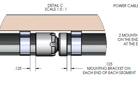
4 Table A Length of luminaire to Power supply Standard power supply 96 Watts Table B Maximum cable length to power supply Standard power supply lead length 11 feet Luminaire watt/foot length / 96 watt supply Luminaire 18 gauge cable 16 gauge cable 14 gauge cable BriteLine BriteLine 35 feet 60 feet 90 feet CaseLine CaseLine 40 feet 60 feet 95 feet EcoLine HO 12 8 EcoLine HO 35 feet 60 feet 90 feet EcoLine LO 8 12 EcoLine LO 40 feet 64 feet 95 feet EcoLine SLO 4 24 EcoLine SLO 55 feet 90 feet 145 feet FineLine HO 5 19 FineLine HO 35 feet 60 feet 90 feet FineLine LO FineLine LO 40 feet 64 feet 95 feet FineLine SLO FineLine SLO 40 feet 64 feet 95 feet Round Clip Fixture Length Minimum Qauntity Req'd. up to 24" 5 24" - 42" 6 42" - 60" 7 60" - 90" 8 90" - 120" 9 Fixture Length First and last section plus section clip Round Flex Clip Minimum Quantity Req'd 3-4" 2 begin / end 1 per section 6-8" 2 begin / end 2 per section INSTALL THE FIXTURE Each Luminaire zone should be wired to one power supply and each zone cannot exceed the allowable length by type of luminaire. First install the mounting clips in the marked locations with the appropriate length and type of screw for the surface that it is being mounted to (See drawings below). Round flex will need one mounting clip per fixture section, up to 6.0 inches sections. Mounting clips must be centered on each fixture section. Two mounting clips are required for fixture sections greater than 12.0 inches. When the clips are securely in place the fixtures can be mounted by simply pushing the fixture into the secured spring clips that are mounted to the surface. When all fixtures are installed in the clips connect the mating connector to the next fixture when that applies.


5
6


7 Round Flex
8 CONNECT THE POWER Connect the secondary power cable from the junction box/power supply to the power lead on the first Round Luminaire in the series using the mating connectors at the ends of the wires to finalize the power connection. ROUND SPECIFICATIONS COLOR TEMPERATURE Warm White 2700K 3000K 3500K 4000K Cool White 4500K 5000K Additional colors are available upon request HOUSING Anodized Aluminum Cable 2 wire and 3 wire 18AWG with Molex mating connectors LISTINGS UL 2108 ELECTRICAL SPECIFICATIONS INPUT 24VDC JUNCTION BOX/POWER SUPPLY MJT-LP GG-29 ENVIRONMENTAL SPECIFICATIONS TEMPERATURE RANGE -4ºF to 104ºF (-20ºC to 40ºC) SPACING REQUIREMENTS minimum 4 one each side of supply and 2 above is power supply instruction in box. U.S. AND FOREIGN PATENTS AND PATENTS PENDING U.S. Patent #6,573,536, U.S. Patent #6,815,724, and U.S. Patent #6,831,303, U.S. Patent # 7,242,028, U.S. Patent #7,288,796,other patents pending. OptoLum Inc. grants the purchaser of its lighting products and controllers a personal and non-transferable license to use ThermoLum, its patented technology for thermally optimized LED-based lighting fixtures for illumination, display and design. This license is granted only by OptoLum Inc., and may not be transferred except by the grantor. The design, duplication, manufacture, or sale of other products using thermally optimized LEDbased lighting may be prohibited and is not licensed hereunder. OptoLum, Inc. All rights reserved. OptoLum and the OptoLum logo are registered trademarks, and ThermoLum, BriteLine, OptoLine, MegaLine, MicroMod, MiniMod, MegaMod, and VariLum are trademarks of OptoLum, Inc. All other brand or product names are trademarks or registered trademarks of their respective owners. Specifications subject to change without notice. SOURCE LIFE OptoLum illumination products utilize high brightness LEDs as the illumination source. LED manufacturers predict LED life of up to 50,000 hours at 70% of lamp lumen output, however, like all basic light sources, LEDs also experience lumen depreciation over time. So while LEDs can emit light for an extremely long period of time, MTBF is not the only consideration in determining useful life. LED lumen depreciation is affected by numerous environmental conditions such as ambient temperature, humidity and ventilation. Lumen depreciation is also affected by means of control, thermal management, current levels, and a host of other electrical design considerations. OptoLum systems are expertly engineered to optimize LED life when used under normal operating conditions [ambient temperature: -4 F to 104 F (-20 C to 40 C), humidity: 0-95% non-condensing humidity, adequate ventilation and air volume]. Long-term operation outside of these ranges or conditions, or at the upper limits of these ranges or conditions, may subject the product to further degradation of the LED source life, or in extreme cases, failure of internal components. Source life information is based on LED manufacturer s data, as well as other third party testing.
9 THREE YEAR LIMITED HARDWARE WARRANTY OptoLum, Inc. warrants its products, if properly used and installed, will be free from defects in materials and workmanship and will substantially conform to OptoLum s publicly available specifications for a period of three (3) year after the date the product was purchased by the end user. If the product fails during the warranty period, purchaser s remedy under this limited warranty shall be at OptoLum s sole election: Repair the product by means of hardware and/or software or Replace the product with another product This limited warranty does not cover damages due to external causes, including, but not limited to, accident, problems with electrical power, usage not in accordance with product instructions, misuse, neglect, modification, repair, improper installation, or improper testing. OptoLum is not responsible for indirect, incidental, or consequential damages resulting from any breach of warranty or under any other legal theory including, but not limited to, lost profits, downtime, goodwill, damage to or replacement of equipment and property. All Damage claims must be reported within 30 days of purchase. To obtain warranty service, you may contact your distributor in accordance with its instructions, or you may contact OptoLum. To request warranty service you should call OptoLum during the warranty period. Proof of purchase is required. When calling within warranty, please provide: 1) Your name, shipping address, and telephone number 2) A description of the model 3) An explanation of the problem A Return Authorization (RA) number & ship-to address will be provided to send the product back. The warranty and remedies set forth above are exclusive and in lieu of all others, whether oral or written, express or implied. OptoLum specifically disclaims any and all implied warranties, including, without limitation, warranties of merchantability and fitness for a particular purpose. No OptoLum distributor, dealer, agent or employee is authorized to make any modification, extension, or addition to this warranty. This warranty gives you specific legal rights, and you may also have other rights that vary from jurisdiction to jurisdiction. Unless modified in writing signed by both OptoLum and Purchaser/User, this Limited Warranty is understood to be the complete and exclusive agreement between OptoLum and Purchaser, including without limitation any statements made by salespersons or other representatives of OptoLum. No employee or other representative of OptoLum or any other party is authorized to make any warranty in addition to the warranty contained in this document. Items Explicitly NOT covered by this Warranty. OptoLum does not warrant: Defects caused by failure to provide a suitable installation environment (i.e., temperature above 104 F, humidity above 95%). Acts of God including but not limited to lightning surges, flooding, or earthquakes. Damage caused during shipment. Damage caused by any primary side (line voltage) power source problem including but not limited to unregulated power, short circuits, or lightning induced power surges. Damage caused by use of product for purposes other than those for which it was designed. Products incorporating white LED s (Light Emitting Diodes) are not covered for color temperature variations or changes, brightness reduction or diminished light output. Products installed by other than electricians, will not be covered. OPTOLUM DOES NOT COVER LABOR COST ASSOCIATED WITH REPLACEMENT OF PRODUCTS IN END APPLICATIONS. OPTOLUM CANNOT WARRANTY OR EXTEND ITS WARRANTY TO WORK PROVIDED BY OUTSIDE CONTRACTORS. OPTOLUM WILL HOWEVER WARRANTY LABOR IF THE INSTALLATION IS DONE BY OPTOLUM QUALIFIED PERSONNEL. OptoLum, Inc W. 10 th Place Suite 107 Tempe, AZ Tel Fax info@optolum.com
Cove Light AC HO RGB Graze INSTALLATION GUIDE V0.2. Cover: Cove Light AC HO-9 RGB Graze Cove Light AC HO-36 RGB Graze
 Cove Light AC HO RGB Graze INSTALLATION GUIDE V0.2 Cover: Cove Light AC HO-9 RGB Graze Cove Light AC HO-36 RGB Graze CONTENT 1. INTRODUCTION 3 2. INSTALLATION 6 3. SAFETY AND OPERATION 10 4. SYSTEM CONFIGURATION
User Guide. Control Box. RoscoLED TM.
 RoscoLED TM Control Box User Guide This guide applies to the following RoscoLED Control Box models: RoscoLED Control Box 300W/Static White (293 22250 0000) RoscoLED Control Box 400W/VariWhite (293 22260
3 RGBW RECESSED LIGHTING MANUAL
 3 RGBW RECESSED LIGHTING MANUAL Coloronix, Inc. 5461 West Jefferson Boulevard Los Angeles, California 90016 (323) 677-4242 http://www.rgbw.com Page 1 - Coloronix RGBW Recessed Lighting Manual V2.0_3 Coloronix,
Chore-Tronics Mobile Server
 Chore-Tronics Mobile Server Installation & Operator s Instruction Manual Contact your nearby Chore-Time distributor or representative for additional parts and information. Chore-Time Group A division of
Broadband Automatic Disconnect Switch. User Manual
 Reset/Test Primary/ Primary Broadband Automatic Disconnect Switch User Manual Local Power Remote Pwer Local 63V Fault Secondary Select Secondary 220V Normal 990-1929 09/2004 Introduction Introduction
S82S (3/7.5-W Models)
") Switch Mode Power Supply (3/7.5-W Models) CSM DS_E_4_3 Miniature DIN Rail Mounting DC-DC Power Supplies 65 mm depth enables mounting onto control panels with 100 mm depth. Inputs: 10.2 to 27.6 VDC (DC
Switch Mode Power Supply (3/7.5-W Models) CSM DS_E_4_3 Miniature DIN Rail Mounting DC-DC Power Supplies 65 mm depth enables mounting onto control panels with 100 mm depth. Inputs: 10.2 to 27.6 VDC (DC
GOLDENI. Owners Manual & Safety Instructions. English. model# GOLDi600. Copyright 2017 Smart Grow Technologies, INC All Rights Reserved
 GOLDENI 600 model# GOLDi600 English Copyright 2017 Smart Grow Technologies, INC All Rights Reserved Owners Manual & Safety Instructions INTRODUCTION This User Manual is for Smart Grow Technologies (SGS):
iconverter 2-Module Power Chassis
 iconverter 2-Module Power Chassis User Manual 38 Tesla, Irvine, CA 92618 USA Phone: (949) 250-6510; Fax: (949) 250-6514 Page 1 Warning The operating description in this Instruction Manual is for use by
Omnitron Systems Technology, Inc. 1. iconverter. 19-Module Managed Power Chassis User s Manual
 Omnitron Systems Technology, Inc. 1 iconverter 19-Module Managed Power Chassis User s Manual 27 Mauchly, #201, Irvine, CA 92618 Phone: (949) 250-6510; Fax: (949) 250-6514 2 Omnitron Systems Technology,
Nano Liner Allegro AC XB RGB / DW INSTALLATION GUIDE V1.2
 Nano Liner Allegro AC XB RGB / DW INSTALLATION GUIDE V1.2 Cover: Nano Liner Allegro AC XB-9 RGB Nano Liner Allegro AC XB-18 RGB Nano Liner Allegro AC XB-27 RGB Nano Liner Allegro AC XB-36 RGB Nano Liner
Turbo Fiberglass Cone Fan and Grill Fan 36 Direct Drive. Installation & Operator s Instruction Manual
 Turbo Fiberglass Cone Fan and Grill Fan 36 Direct Drive Installation & Operator s Instruction Manual July 1998 MV1384B Chore-Time TURBO TM Fan Extended Warranty Chore-Time Equipment warrants new TURBO
Surge Protective Devices Installation, Operation and Maintenance Manual. LoadTrack LTL
 LoadTrack LTL Surge Protective Devices Installation, Operation and Maintenance Manual P.O. Box 3760 Winter Park, FL 32790 USA TEL: 800-647-1911 www.tpssurge.com LOADTRACK LTL INSTALLATION, OPERATION AND
SS2 - DIRECT POWER LIGHTING MANUAL
 SS2 - DIRECT POWER LIGHTING MANUAL Coloronix, Inc. 5461 West Jefferson Boulevard Los Angeles, California 90016 (323) 677-4242 http://www.rgbw.com Coloronix, Inc. 2012 Coloronix, Inc. All rights reserved.
Installation, Testing, and Operating Procedures 30 AMP PORTABLE AND PERMANENT SERIES GFCI SINGLE and MULTIPHASE
 IMPORTANT! Please read all the information on this sheet. SAVE THESE INSTRUCTIONS! NOTICE BEFORE USING READ INSTRUCTIONS COMPLETELY. TO BE INSTALLED BY A QUALIFIED ELECTRICIAN IN ACCORDANCE WITH NATIONAL
ew Downlight SM Installation Guide An EssentialWhite Product
 Installation Guide ew Downlight SM An EssentialWhite Product ew Downlight SM Powercore is a low-profile, surface-mounted downlight for basic white illumination. The ew Downlight SM Powercore fixture is
G3NE. Model Number Structure. Solid State Relays. Model Number Legend. Compact, Low-cost, SSR Switching 5 to 20 A
 Solid State Relays CSM DS_E_4_1 Compact, Low-cost, SSR Switching 5 to 20 A Wide load voltage range: 75 to 264 VAC. Both 100-V and 200-V loads can be handled with the same model. Dedicated, compact aluminum
RGBW PATHWAY LIGHTING MANUAL
 RGBW PATHWAY LIGHTING MANUAL Coloronix, Inc. 5461 West Jefferson Boulevard Los Angeles, California 90016 (323) 677-4242 http://www.rgbw.com Page 1 Coloronix RGBW Pathway Lighting Manual V1.0 Coloronix,
1X2 HDMI Splitter with 3D Support
 AV Connectivity, Distribution And Beyond... VIDEO WALLS VIDEO PROCESSORS VIDEO MATRIX SWITCHES EXTENDERS SPLITTERS WIRELESS CABLES & ACCESSORIES 1X2 HDMI Splitter with 3D Support Model #: SPLIT-HDM3D-2
PIXIM Micro Dome Camera
 PIXIM Micro Dome Camera DWC-MC355T ABOUT MANUAL Before installing and using the camera, please read this manual carefully. Be sure to keep it handy for future reference. 07132012 PRECAUTIONS Do not open
Demo Kit Quick Start Guide
 Near Field Imaging (NFI) Projected Capacitive Touch Screen Systems Read and understand all safety information contained in this document before using this product. Introduction This is intended to help
burst laser
 burst laser USERS MANUAL www.venuelightingeffects.com Introduction Congratulations on your purchase of Venue s Burst Laser. Designed to operate as a simple stand-alone unit or external addition to your
Installation. MGE Galaxy 3500 and Smart-UPS VT. Maintenance Bypass, Distribution and Transformer Cabinet
 Installation MGE Galaxy 3500 and Smart-UPS VT Maintenance Bypass, Distribution and Transformer Cabinet American Power Conversion Legal Disclaimer The information presented in this manual is not warranted
Bluetooth Ceiling Fan Control with App Owner's Manual
 READ AND SAVE THESE INSTRUCTIONS 0 Model Number RCBT00 Bluetooth Ceiling Fan Control with App Owner's Manual -Speed Hand Held Transmitter Single Light Supplied with Receiver Includes Light Dimming Selection
powerbrite led Lighting Systems & Modules
 powerbrite led Lighting Systems & Modules Instructions for Model PowerBrite LED #1643, 1644, 1645, 1646, 1647, 1648 Important Safety Instructions... Page 2 Installation Instructions... Page 4 Warranty...
4 Port USB Power Hub. Model: JH-800 USER MANUAL
 by 4 Port USB Power Hub Model: JH-800 USER MANUAL BEFORE INSTALLING AND USING THE PRODUCT, PLEASE READ THE INSTRUCTIONS THOROUGHLY, AND RETAIN THEM FOR FUTURE REFERENCE. Charging Port PRODUCT OVERVIEW
OT DMX RGB Installation Guide
 www.sylvania.com OT DMX RGB Installation Guide This installation guide outlines the stepby-step instructions to properly install and configure the OT DMX RGB control interface with a DMX controller. This
VALENT 12V PREMIUM LED STRIP LIGHT
 DRY LOCATION SUITABLE FOR CLOSET USE DIMMABLE 12VDC VALENT 12V PREMIUM LED STRIP LIGHT Medium & high brightness Superior CRI Indoor / dry location UL Listed & R/C SAM Manual Suitable for closet use 5-Year
Model 2460-KIT. Screw Terminal Connector Kit. Description / September 2014 *P * 1
 Keithley Instruments 28775 Aurora Road Cleveland, Ohio 44139 1-800-935-5595 http://www.keithley.com Model 2460-KIT Screw Terminal Connector Kit Description The Model 2460-KIT Screw Terminal Connector Kit
Sensing method Appearance Connection method Sensing distance Model. Pre-wired (2 m) Power supply Application Appearance Function Model
 Power supply Application Appearance Function Model") Small Spot/Mark (Separate Amplifier) EC-VS/VM CSM_EC-VS/VM_DS_E_6_ Extremely thin beam ideal for detection of minute objects and marks Ideal for detection of small objects and slight color differences
Small Spot/Mark (Separate Amplifier) EC-VS/VM CSM_EC-VS/VM_DS_E_6_ Extremely thin beam ideal for detection of minute objects and marks Ideal for detection of small objects and slight color differences
Owner s Manual. TSD-DCPDV DC Power Distribution with Fixed & Variable Outputs. TSD-DCPDV DC Power Distribution. AtlasSound.com
 Owner s Manual with Fixed & Variable Outputs 1 AtlasSound.com Owner s Manual Description The Atlas Sound Variable Block is designed to reduce cost and wiring clutter in installations where multiple DC
MPP1700 User s Manual
 2011 Visionary Solutions, Inc. All rights reserved. Please visit the support section of our website at www.vsicam.com for manuals, other documentation, and software downloads. Visionary Solutions, Inc.
CrystalView DVI Multi INSTALLATION AND OPERATIONS MANUAL Stancliff Road Phone: (281)
") CrystalView DVI Multi INSTALLATION AND OPERATIONS MANUAL 10707 Stancliff Road Phone: (281) 933-7673 Houston, Texas 77099 WWW.ROSE.COM LIMITED WARRANTY Rose Electronics warrants the CrystalView Multi to
CrystalView DVI Multi INSTALLATION AND OPERATIONS MANUAL 10707 Stancliff Road Phone: (281) 933-7673 Houston, Texas 77099 WWW.ROSE.COM LIMITED WARRANTY Rose Electronics warrants the CrystalView Multi to
Installation Manual. 12 Volt Power Supplies. 18-Port. 9-Port RET18PT RET9PT
 12 Volt Power Supplies Installation Manual 9-Port RET9PT 18-Port RET18PT INTRODUCTION Congratulations! The RET9PT 9-Port 12V Power Supply is the perfect solution for your larger security installations.
IntelliBrite Controller (For IntelliBrite Pool, Spa and Landscape Lighting Fixtures) Installation and User s Guide
 Installation and User s Guide") IntelliBrite Controller (For IntelliBrite Pool, Spa and Landscape Lighting Fixtures) Installation and User s Guide *619751* P/N 619751 - Rev B IMPORTANT SAFETY INSTRUCTIONS READ AND FOLLOW ALL INSTRUCTIONS
IntelliBrite Controller (For IntelliBrite Pool, Spa and Landscape Lighting Fixtures) Installation and User s Guide *619751* P/N 619751 - Rev B IMPORTANT SAFETY INSTRUCTIONS READ AND FOLLOW ALL INSTRUCTIONS
The power behind competitiveness. Delta Infrasuite Power Management. Power Distribution Unit. User Manual.
 The power behind competitiveness Delta Infrasuite Power Management Power Distribution Unit User Manual www.deltapowersolutions.com Save This Manual This manual contains important instructions and warnings
Discontinued. 64PXL Board RGB INSTALLATION GUIDE V1.3. Cover: 64PXL Board RGB 8PXL Add-On Strip 16PXL Add-On Board
 64PXL Board RGB INSTALLATION GUIDE V1.3 Cover: 64PXL Board RGB 8PXL Add-On Strip 16PXL Add-On Board CONTENT 1. INTRODUCTION 3 2. INSTALLATION 5 3. SAFETY AND OPERATION 7 4. SYSTEM CONFIGURATION 8 5. CARE
Indoor Dome Camera DWC-D6351D DWC-D6351DB
 Indoor Dome Camera DWC-D6351D DWC-D6351DB ABOUT MANUAL Before installing and using the camera, please read this manual carefully. Be sure to keep it handy for future reference. 10252013 PRECAUTIONS Do
Mini-DVI-WP Series WALL PLATE MINIATURE MULTIMODE FIBER OPTIC DVI TRANSMISSION SYSTEM
 Mini-DVI-WP Series WALL PLATE MINIATURE MULTIMODE FIBER OPTIC DVI TRANSMISSION SYSTEM BCI reserves the right to make changes to the products described herein without prior notice or consent. No liability
HD-SDI Vandal Dome Camera
 HD-SDI Vandal Dome Camera DWC-HF21M4TIR ABOUT MANUAL Before installing and using the camera, please read this manual carefully. Be sure to keep it handy for future reference. 12112013 PRECAUTIONS Do not
LED FOLDING WORKLIGHT TM
 LED FOLDING WORKLIGHT TM LED LIGHT POWERSTRIP USB CHARGING ITM. / ART. 689211 Model: LM55812 CARE & USE INSTRUCTIONS IMPORTANT, RETAIN FOR FUTURE REFERENCE: READ CAREFULLY For assistance with assembly
ATX 450 and ATX 550 Watt Power Supplies
 USER GUIDE ATX 450 and ATX 550 Watt Power Supplies NS-PCW4508/NS-PCW4508-C/NS-PCW5508/NS-PCW5508-C Before using your new product, please read these instructions to prevent any damage. Contents Introduction......................................................3
Owner s Instruction Manual
 Owner s Instruction Manual Advanced Healthcare Telephone Model 5150 Contents IMPORTANT SAFETY INSTRUCTIONS...3 BOX CONTENTS...4 FEATURES...4 ON/OFF SWITCH...4 DIAL BUTTONS...4 RECEIVER VOLUME CONTROL...4
IntelliBrite Controller (For IntelliBrite Pool, Spa and Landscape Lighting Fixtures)
") IntelliBrite Controller (For IntelliBrite Pool, Spa and Landscape Lighting Fixtures) Installation and User s Guide IMPORTANT SAFETY INSTRUCTIONS READ AND FOLLOW ALL INSTRUCTIONS SAVE THESE INSTRUCTIONS
IntelliBrite Controller (For IntelliBrite Pool, Spa and Landscape Lighting Fixtures) Installation and User s Guide IMPORTANT SAFETY INSTRUCTIONS READ AND FOLLOW ALL INSTRUCTIONS SAVE THESE INSTRUCTIONS
FNet Repeater Installation & Operator s Instruction Manual
 FNet Repeater Installation & Operator s Instruction Manual October 2004 CTB Inc. Warranty FNet Repeater CTB Inc. Warranty CTB Inc. warrants each new Chore-Tronics product manufactured by it to be free
IO-AO6X I/O Expansion Module 6 Isolated Analog Outputs
 IO-AO6X I/O Expansion Module 6 Isolated Analog Outputs The IO-AO6X is an I/O Expansion Module that can be used in conjunction with specific Unitronics OPLC controllers. The module offers 6 12-bit isolated
VSD-1MC MANUAL 0-10V / 4-20mA Variable Speed Module with Manual Override
 MANUAL 0-10V / 4-20mA Variable Speed Module with Manual Override Varifan 3 4 5 6 7 MANUAL 2 8 1 OFF 10 9 AUTO MANUAL SPEED Installation / User s Guide This guide will inform the electrician on proper wiring
Installation and Operation Guide for PD5200 and PD5300 Automatic Transfer Switch
 Installation and Operation Guide for PD5200 and PD5300 Automatic Transfer Switch PD52 PD52S & PD52DCS PD53-100 te: The PD52S & PD52DCS are provided with LED lights. The GREEN LIGHTS indicate Shore Power
INSTALLATION AND USER GUIDE 2800MWB SINGLE LINE BASIC FEATURE TELEPHONE
 INSTALLATION AND USER GUIDE 2800MWB SINGLE LINE BASIC FEATURE TELEPHONE TeleMatrix Copyright 2005 COMPLIANCE AND SAFETY As specified by FCC regulation, we are required to inform you of specific governmental
SynJet PAR25 LED Cooler with Heat Sink
 PRODUCT SynJet PAR25 LED Cooler with Heat Sink Assembly Guide Version 1.0 June 2009 Version History Document Name: SynJet PAR25 LED Cooler with Heat Sink Assembly Guide Document Number: MKTG-DOC-00048.
LINE VOLTAGE TESTER CT101 USER S MANUAL. Please read this manual carefully and thoroughly before using this product.
 LINE VOLTAGE TESTER USER S MANUAL CT101 Please read this manual carefully and thoroughly before using this product. KEY FEATURES Visual indication of AC or DC voltage Easy to use approved Safe for CAT
IP67. Luminux Matrix RGB LED Panel. Luminux Matrix RGB LED Panel - LED Space and Diffuser Distance Guide.
 Luminux Matrix RGB LED Panel Luminux Matrix RGB LED panel is a modular LED backlight unit with a bright LED array on a rigid and light weight aluminum circuit board. The panel delivers consistent bright
Model 8020-STC. Kelvin Standard Triaxial Connector Card. Description / October 2014 *P * 1
 Keithley Instruments 28775 Aurora Road Cleveland, Ohio 44139 1-800-935-5595 http://www.keithley.com Model 8020-STC Kelvin Standard Triaxial Connector Card Description The Model 8020-STC Kelvin Standard
Name No. of I/O points Model Safety inputs: 12, test outputs: 4
 Safety I/O s DST1 Series CSM_DST1 Series_DS_E_7_3 Distributed Safety s That Reduce Wiring. Lineup includes four models to accommodate various I/O types and number of I/O points. Monitor the safety system
VESSEL + Todd Bracher. Installation Guide Sconce
 Application Model Number: ((VSL-SC-XX-XX-XXX; All Finishes) VESSEL (the Product ) is a decorative LED luminaire for dry, interior use. The Product is intended for wall-mounted LED lighting for commercial
E2EY. A Proximity Sensor for Aluminum, Brass and Other Non-ferrous Metals. Iron Is Not Detected. Aluminum-detecting Proximity Sensor
 Aluminum-detecting Proximity Sensor EEY CSM_EEY_DS_E_5_1 A Proximity Sensor for Aluminum, Brass and Other Non-ferrous Metals. Iron Is Not Detected. Non-ferrous metals, such as aluminum and brass, are detected.
I/O Expansion Box Installation & Operator s Instruction Manual
 I/O Expansion Box Installation & Operator s Instruction Manual May 2004 CTB Inc. Warranty I/O Expansion Box CTB Inc. Warranty CTB Inc. warrants each new Chore-Tronics product manufactured by it to be free
MODELS DSH/DSV R-410A AIR SIDE ECONOMIZER KIT
 MODELS DSH/DSV R-410A AIR SIDE ECONOMIZER KIT Form 145.11-IOM1 (412) AIR SIDE ECONOMIZER FOR DSH AND DSV R-410A AIR COOLED AIR CONDITIONING UNITS INSTALLATION INSTRUCTIONS B Style IMPORTANT! READ BEFORE
E3Z-G. Photoelectric Sensor with Grooved Design and Easy Settings. Grooved-type Photoelectric Sensor with Built-in Amplifier. Ordering Information
 Grooved-type with Built-in Amplifier EZ-G CSM_EZ-G_DS_E_9_ with Grooved Design and Easy Settings Groove-type with groove width of 5 mm. Models are available with one or two light axes. Models are available
Line reactors SINAMICS. SINAMICS G130 Line reactors. Safety information 1. General. Mechanical installation 3. Electrical installation
 Safety information 1 General 2 SINAMICS SINAMICS G130 Mechanical installation 3 Electrical installation 4 Technical specifications 5 Operating Instructions Control version V4.7 04/2014 A5E00331462A Legal
Vocia ELD-1. Operation Manual
 Vocia Operation Manual Biamp Systems 9300 S.W. Gemini Drive, Beaverton, Oregon 97008 U.S.A. (503) 641-7287 www.biamp.com table of contents Vocia End of Line Device () features....3 setup and use...............................................................................
20W Tungsten-Halogen Light Source. Operation Manual
 20W Tungsten-Halogen Light Source - ASB-W-020 - Operation Manual Important Safety Notices 1. Never look directly into the light beam, including through the cooling fan while light is on, as this can cause
MODELS DSH/DSV R-410A AIR SIDE ECONOMIZER KIT
 MODELS DSH/DSV R-410A AIR SIDE ECONOMIZER KIT Form 145.11-IOM1 (412) AIR SIDE ECONOMIZER FOR DSH AND DSV R-410A AIR COOLED AIR CONDITIONING UNITS INSTALLATION INSTRUCTIONS B Style IMPORTANT! READ BEFORE
RESIDENTIAL OPERATOR MOTOR CONTROL BOARD REPLACEMENT INSTRUCTIONS
 READ THIS MANUAL CAREFULLY BEFORE BEGINNING INSTALLATION RESIDENTIAL OPERATOR MOTOR CONTROL BOARD REPLACEMENT INSTRUCTIONS PRODUCT FEATURES MODELS: IIA SPRINT 310/510/710 200/250 2000 SERIES 3000 SERIES
Rhino Redundancy Module PSM24-REM360S. Operating Instructions
 Rhino Redundancy Module PSM4-REM360S Operating Instructions RHINO REDUNDANCY MODULE PSM4-REM360S Description With this module and two power supplies of the PSM series (78, 90, 56, 80 and 360 watt models),
SCHOTT FLM 4 Fiber Lighting Modul. Operating Instructions
 SCHOTT FLM 4 Fiber Lighting Modul Operating Instructions Contents 1. Important information 3 2. Scope of Delivery 3 3. Intended use 3 4. Safety information 4 5. Operation 5 5.1. LED Optics Module 5 5.2.
Dear Customer, User Memo: Please visit us on facebook or twitter! Thank you for purchasing this product.
 Dear Customer, Thank you for purchasing this product. For optimum performance and safety, please read these instructions carefully. User Memo: Date of purchase: Dealer name: Dealer address: Dealer website:
i-series Videoconference Fixture
 TM i-series Videoconference Fixture Operating Instructions 580 Mayer Street, Building #7, Bridgeville, PA 15017 phone 412.206.0106 fax 412.206.0146 www.brightlines.com 2013 Brightline, L.P. Safety To prevent
SATA II HDD Canister KISS DA 435 Quick Reference Guide
 SATA II HDD Canister KISS DA 435 Quick Reference Guide If it s embedded, it s Kontron 1. Table of Contents SATA II HDD Canister KISS DA 435 1. Table of Contents 1. Table of Contents... 1 2. Important Information...
Dell Networking S4810 Open Networking (ON) Getting Started Guide
 Getting Started Guide") Dell Networking S4810 Open Networking (ON) Getting Started Guide Regulatory Model: S4810 Notes, Cautions, and Warnings NOTE: A NOTE indicates important information that helps you make better use of your
Dell Networking S4810 Open Networking (ON) Getting Started Guide Regulatory Model: S4810 Notes, Cautions, and Warnings NOTE: A NOTE indicates important information that helps you make better use of your
MTP INSTRUCTION MANUAL
 DT-118B MTP INSTRUCTION MANUAL Pocket Autoranging Digital Multimeter 3 in 1 Model MTP-1025 Auto Ran ging DMM Hz% A OFF V AU TO PO WER OFF MTP Instruments Table of Contents Introduction Page 1 Features
M22. Round Indicator Series with 22 dia. and 25 dia. (when using a ring) Indicator (Cylindrical 22/25-dia.) List of Models. Model Number Structure
 Indicator (Cylindrical 22/25-dia.) List of Models. Model Number Structure") Indicator (Cylindrical 22/25-dia.) CSM DS_E_3_4 Round Indicator Series with 22 dia. and 25 dia. (when using a ring) Same type as the A22-series Pushbutton Switches. Use 25-dia. ring to install in 25-dia.
Indicator (Cylindrical 22/25-dia.) CSM DS_E_3_4 Round Indicator Series with 22 dia. and 25 dia. (when using a ring) Same type as the A22-series Pushbutton Switches. Use 25-dia. ring to install in 25-dia.
USB 3.0 Spectra
 USB 3.0 Spectra 3001-15 1-Port USB 3.0 15m Active Extension Cable User Guide Thank you for purchasing the Icron USB 3.0 Spectra 3001-15. Please read this guide thoroughly. This document applies to Part
EMS. Electrical Management System. Progressive Industries Incorporated Morrisville, North Carolina
 Progressive Industries Warranty Progressive warrants its products are free from defects in materials and workmanship for a period of three years. This is in lieu of all other warranties, obligations, or
G3B/G3BD. Model Number Structure. Ordering Information. Solid State Relays Model Number Legend. List of Models
 Solid State Relays G3@-VD CSM_G3B_G3BD_DS_E_5_1 International Standards for G3B Series, Same Profile as MK Power Relays Shape-compatible with mechanical relays. Certified by UL, CSA, and VDE (models numbers
AC4G-D User s Manual
 AC4G-D User s Manual Entire contents of this manual 2004 Active Cool Ltd. Ashkelon, Israel. Reproduction in whole or in part without permission is prohibited. Active Cool and AC4G-D are registered of Active
PRO-1250D CT MID DIN rail three phase four wire energy meter.
 PRO-1250D CT MID DIN rail three phase four wire energy meter. 1.1 Safety instructions 1.2 Foreword 1.3 MID certificate 1.4 Performance criteria 1.5 Specifications 1.6 Basic errors 1.7 Description 1.8 Dimensions
4300 WINDFERN RD #100 HOUSTON TX VOICE (713) FAX (713) web: IMPORTANT!!!
 FAX (713) web: IMPORTANT!!!") 4300 WINDFERN RD #100 HOUSTON TX 77041-8943 VOICE (713) 973-6905 FAX (713) 973-9352 web: www.twrlighting.com IMPORTANT!!! PLEASE TAKE THE TIME TO FILL OUT THIS FORM COMPLETELY. FILE IT IN A SAFE PLACE.
4300 WINDFERN RD #100 HOUSTON TX 77041-8943 VOICE (713) 973-6905 FAX (713) 973-9352 web: www.twrlighting.com IMPORTANT!!! PLEASE TAKE THE TIME TO FILL OUT THIS FORM COMPLETELY. FILE IT IN A SAFE PLACE.
LIFX is color changing, Wi-Fi lighting that you control with your smartphone or tablet.
 LIFX.COM MEET YOUR NEW LIFX LIFX is color changing, Wi-Fi lighting that you control with your smartphone or tablet. With the LIFX app you can switch your lights on and off, dim, adjust brightness and
ULTRA BLAZE 12V & 24V LED TAPE LIGHT
 DRY LOCATION SUITABLE FOR CLOSET USE DIMMABLE 12VDC 24VDC 12V & 24V LED TAPE LIGHT Very High Brightness 16.4 ft. maximum run (12V) 2 ft. maximum run (24V) UL Listed & R/C SAM Manual Suitable for closet
Carefree-Security. Installation and programming instructions 1050A. Owner s Manual
 Carefree-Security Heavy Duty Commercial - Industrial Fully Sealed Digital Access Keypad Specially Designed for Gate Operators, Overhead Doors, Specialty Doors & Electric Door Locking Devices SINGLE OR
User's Guide. Model High Precision Quad Output DC Power Supply
 User's Guide Model 382270 High Precision Quad Output DC Power Supply Introduction Congratulations on your purchase of the Extech 382270 DC Power Supply. The Model 382270 can be used for many applications
Model 8020-KHV. Kelvin Keithley Triaxial Connector Card. Description / October 2014 *P * 1
 Keithley Instruments 28775 Aurora Road Cleveland, Ohio 44139 1-800-935-5595 http://www.keithley.com Model 8020-KHV Kelvin Keithley Triaxial Connector Card Description The Model 8020-KHV Keithley HV Connector
Configurable Output Distribution. 120V / 208V / 240V 60Hz. User Manual English
 Configurable Output Distribution 120V / 208V / 240V 60Hz User Manual English TABLE OF CONTENTS IMPORTANT SAFETY INSTRUCTIONS.......................... 1 GLOSSARY OF SYMBOLS....................................
Sapling Converter Box
 Installation Manual Sapling Converter Box SCB-100-000-1 Version Number 1.2 Current as of March 15, 2015 The Sapling Company, Inc. (+1) 215.322.6063 P. (+1) 215.322.8498 F. 2-Wire Converter Box (SCB-100-000-1)
TSD-SEQ6 Sequencer Controller
 Owner s Manual 1 AtlasSound.com Owner s Manual Description The Atlas Sound features 6 outputs that are configurable individually to be either a 24VDC output or Hard Switch Contact Closure (CC). There are
Analog High Definition Micro Dome Camera
 Analog High Definition Micro Dome Camera DWC-MC753WTIR ABOUT MANUAL Before installing and using the camera, please read this manual carefully. Be sure to keep it handy for future reference. 04172015 PRECAUTIONS
E2K-F. Flat Capacitive Sensor with a Thickness of Only 10 mm. Flat Proximity Sensor. Ordering Information. Sensors [Refer to Dimensions on page 4.
 Flat Proximity Sensor EK-F CSM_EK-F_DS_E Flat Capacitive Sensor with a Thickness of Only mm Flat Sensor with excellent space efficiency. (Model with built-in Amplifier is only mm thick.) Direct mounting
Tempco Instruction Manual
 Tempco Instruction Manual 1/16 DIN Solid State Temperature Controller Relay Output Solid State Output For Heating Model Numbers: TEC-901, TEC-902, TEC-905 Temperature controls in this series are designed
CSM_PYF S/P2RF- -S_DS_E_2_5
 Screwless Clamp Terminal Sockets PYF@@S/P2RF-@@-S CSM_PYF S/P2RF- -S_DS_E_2_5 New Screwless Terminal Sockets Added for MY and G2R Relays. Simplified wiring without tightening screws. Two wires can be independently
Dual Component Video Wall Plate 6-RCA AT80COMP6
 Dual Component Video Wall Plate 6-RCA AT80COMP6 User Manual www.atlona.com TABLE OF CONTENTS 1. Introduction 2 2. Applications 2 3. Specifications 2 4. Installation 2 5. Safety Information 3 6. Warranty
Model 2380 Rack-Mount Kit
 Keithley Instruments 28775 Aurora Road Cleveland, Ohio 44139 1-800-935-5595 http://www.tek.com/keithley Model 2380 Rack-Mount Kit Installation Instructions Introduction The Model 2380 Fixed Rack-Mount
XBDM. 1015LV, 1020LV, 1030LV, 1020HV Models USER & INSTALLATION MANUAL BYPASS DISTRIBUTION MODULE
 XBDM 1015LV, 1020LV, 1030LV, 1020HV Models USER & INSTALLATION MANUAL www.xpcc.com 2013 Xtreme Power Conversion Corporation. All rights reserved. Table of Contents IMPORTANT SAFETY INSTRUCTIONS:... 4 INTRODUCTION...
User's Guide. Phase Sequence and Motor Rotation Tester Model
 User's Guide Phase Sequence and Motor Rotation Tester Model 480403 Introduction Congratulations on your purchase of the Extech Model 408403 Motor and Phase Rotation Indicator. This handheld instrument
QuickTouch (QT4) Owner s Manual
 Owner s Manual") QuickTouch (QT4) Owner s Manual 4-Function Hand-Held Wireless Remote Control IMPORTANT SAFETY INSTRUCTIONS READ AND FOLLOW ALL INSTRUCTIONS SAVE THESE INSTRUCTIONS Table of Contents SECTION I. APPLICATION...
QuickTouch (QT4) Owner s Manual 4-Function Hand-Held Wireless Remote Control IMPORTANT SAFETY INSTRUCTIONS READ AND FOLLOW ALL INSTRUCTIONS SAVE THESE INSTRUCTIONS Table of Contents SECTION I. APPLICATION...
Ordering Information. I/O Relay G7T. Model Number Legend Slim-styled I/O Relay Saves Space in Panel
 I/O Relay CSM DS_E_4_4 Slim-styled I/O Relay Saves Space in Panel SPST-NO, SPST-NC, and SPDT contact forms available for output (SPST-NO only for input). Ultra-slim housing measuring 29 (W) x 0 (D) x 2
Logitech Alert 700i/750i System Requirements & Support Guide
 Logitech Alert 700i/750i System Requirements & Support Guide Contents System Requirements............................ 3 Product Information............................ 4 Contact Us..................................
DVI Extender over Single CAT5 Mini SET
 DVI Extender over Single CAT5 Mini SET Model #: DVI-C5-M-SET 2010 Avenview Inc. All rights reserved. The contents of this document are provided in connection with Avenview Inc. ( Avenview ) products. Avenview
INSTALLATION AND MOUNTING MANUAL
 INSTALLATION AND MOUNTING MANUAL HyperSpike TCPA-10 PART NO.: xxxxxxxxx Copyright Ultra Electronics USSI Columbia City, IN 46725 USA REV A HyperSpike TCPA - 10 Installation and Mounting Manual This manual
P O W E R S U P P L Y M A N U A L
 POWER SUPPLY MANUAL Congratulations on the purchase of your new Corsair power supply. This User Agreement (the Agreement ) is a legal agreement between you ( You ), and Corsair Memory, Inc. ( Corsair ).
X-12s Users Manual. X-12s User Manual Revisions Revision Description Initial release. Xytronix Research & Design, Inc.
 X-12s User Manual Revisions Revision Description 1.0 Page 2 Initial release Introduction Section 1: Introduction The X-12s 8-Relay expansion module is used with the X-600M controller. The X-12s has eight