Network Layer: outline
|
|
|
- Gerard Cunningham
- 5 years ago
- Views:
Transcription
1 Network Layer: outline 1 introduction 2 virtual circuit and datagram networks 3 what s inside a router 4 IP: Internet Protocol datagram format IPv4 addressing ICMP IPv6 5 routing algorithms link state distance vector hierarchical routing 6 routing in the Internet RIP OSPF BGP 7 broadcast and multicast routing 1

2 Figure Internet as a block box Application Application Transport Transport Network Data link Message Message Network Data link Physical Physical Internet A B 2

3 Figure Internet as a combination of LANs and WANs connected together 3
4 SWITCHING From the previous discussion, it is clear that the passage of a message from a source to a destination involves many decisions. When a message reaches a connecting device, a decision needs to be made to select one of the output ports through which the packet needs to be send out. In other words, the connecting device acts as a switch that connects one port to another port. 4
5 Circuit Switching A physical circuit (channel) is established between the source and destination before the delivery of the message Never implemented at the network layer; it is mostly used at the physical layer In circuit switching, the whole message is sent from the source to the destination without being divided into packets. 5
6 Packet Switching Datagram approach Virtual circuit approach In packet switching, the message is first divided into manageable packets at the source before being transmitted. The packets are assembled at the destination. 6
7 Figure A connectionless packet-switched network Network R1 A connectionless packet-swtiched network 2 R2 Sender R Network R3 R5 Out of order Receiver 7
8 Network layer transport segment from sending to receiving host on sending side encapsulates segments into datagrams on receiving side, delivers segments to transport layer network layer protocols in every host, router router examines header fields in all IP datagrams passing through it application transport network data link physical network data link physical network data link physical network data link physical network data link physical network data link physical network data link physical network data link physical network data link physical network data link physical network data link physical network data link physical application transport network data link physical 8
9 Two key network-layer functions forwarding: move packets from router s input to appropriate router output routing: determine route taken by packets from source to dest. routing algorithms analogy: routing: process of planning trip from source to dest forwarding: process of getting through single interchange 9
10 Interplay between routing and forwarding routing algorithm local forwarding table header value output link routing algorithm determines end-end-path through network forwarding table determines local forwarding at this router value in arriving packet s header
11 Network Layer: outline 1 introduction 2 virtual circuit and datagram networks 3 what s inside a router 4 IP: Internet Protocol datagram format IPv4 addressing ICMP IPv6 5 routing algorithms link state distance vector hierarchical routing 6 routing in the Internet RIP OSPF BGP 7 broadcast and multicast routing 11
12 Connection, connection-less service datagram network provides network-layer connectionless service virtual-circuit network provides network-layer connection service analogous to TCP/UDP connection-oriented / connectionless transport-layer services 12
13 Figure A connectionless packet-switched network Network R1 A connectionless packet-swtiched network 2 R2 Sender R Network R3 R5 Out of order Receiver 13
14 Figure Forwarding process in a connectionless network Routing table Destination address A B Output interface 1 2 Legend SA: Source address DA: Destination address Destination address H 3 Send the packet out of interface 2 SA DA Data 1 2 SA DA Data 3 4 In a connectionless packet-switched network, the forwarding decision is based on the destination address of the packet. 14
15 Total delay Figure Delay in a connectionless network Souce Destination Time Time Time Time 15

16 Figure A connection-oriented packet switched network
17 Figure Forwarding process in a connection-oriented network Incoming Port 1 Routing Table Label L1 Outgoing Port 2 Label L2 Legend SA: Source address DA: Destination address L1, L2: Labels In a connection-oriented packet switched network, the forwarding decision is based on the VC number of the packet. 17
18 Figure Sending request packet in a virtual-circuit network Network Incoming Port 1 A to B Label 14 Outgoing Port 3 Label Legend A to B Request packet Virtual circuit A 1 A to B 2 1 R1 3 A to B 2 4 R5 R2 Network 1 R A to B 1 3 R4 4 4 A to B B Incoming Port 1 Label Port 66 3 A to B Outgoing Label Incoming Port 1 Label Port 22 4 A to B Outgoing Label 18
19 Figure Setup acknowledgement in a virtual-circuit network Network Incoming Port 1 A to B Label 14 Outgoing Port 3 Label Legend Acknowledge packet Virtual circuit A R R5 R2 Network R R B Incoming Outgoing Port Label Port Label A to B Incoming Port 1 Label Port 22 4 A to B Outgoing Label 19
20 Figure Flow of one packet in an established virtual circuit Network Incoming Port 1 A to B Outgoing Label Port Label Legend A B Data Datagram Virtual circuit A 14 A B Data R A B Data R5 R2 Network R A B Data 77 A B Data R4 Incoming Port 1 Label Port 66 3 A to B Outgoing Label 22 Incoming Port 1 Label Port 22 4 A to B Outgoing Label 77 20
21 Teardown Total delay Setup Figure Delay in a connection-oriented network Source Destination Transmission time Time Time Time Time 21
22 Virtual circuits source-to-dest path behaves much like telephone circuit performance-wise network actions along source-to-dest path call setup, teardown for each call before data can flow each packet carries VC identifier (not destination host address) every router on source-dest path maintains state for each passing connection link, router resources (bandwidth, buffers) may be allocated to VC (dedicated resources = predictable service) 22
23 VC implementation a VC consists of: 1. path from source to destination 2. VC numbers, one number for each link along path 3. entries in forwarding tables in routers along path packet belonging to VC carries VC number (rather than dest address) VC number can be changed on each link. new VC number comes from forwarding table 23
24 VC forwarding table forwarding table in northwest router: VC number interface number Incoming interface Incoming VC # Outgoing interface Outgoing VC # VC routers maintain connection state information! 24
25 Virtual circuits: signaling protocols used to setup, maintain teardown VC used in ATM, frame-relay, X.25 not used in today s Internet application transport network data link physical 5. data flow begins 6. receive data 4. call connected 3. accept call 1. initiate call 2. incoming call application transport network data link physical 25
26 Datagram networks: Connectionless no call setup at network layer routers: no state about end-to-end connections no network-level concept of connection packets forwarded using destination host address application transport network data link physical 1. send datagrams 2. receive datagrams application transport network data link physical 26
27 Datagram forwarding table routing algorithm local forwarding table dest address output link address-range 1 address-range 2 address-range 3 address-range billion IP addresses, so rather than list individual destination address list range of addresses (aggregate table entries) IP destination address in arriving packet s header
28 Datagram forwarding table Destination Address Range through through through otherwise Link Interface Q: but what happens if ranges don t divide up so nicely? 28
29 Longest prefix matching longest prefix matching when looking for forwarding table entry for given destination address, use longest address prefix that matches destination address. examples: Destination Address Range *** ********* ********* *** ********* otherwise DA: DA: Link interface which interface? which interface? 29
30 Datagram or VC network: why? Internet (datagram) data exchange among computers elastic service, no strict timing req. many link types different characteristics uniform service difficult smart end systems (computers) can adapt, perform control, error recovery simple inside network, complexity at edge ATM (VC) evolved from telephony human conversation: strict timing, reliability requirements need for guaranteed service dumb end systems telephones complexity inside network 30
31 Network Layer: outline 1 introduction 2 virtual circuit and datagram networks 3 what s inside a router 4 IP: Internet Protocol datagram format IPv4 addressing ICMP IPv6 5 routing algorithms link state distance vector hierarchical routing 6 routing in the Internet RIP OSPF BGP 7 broadcast and multicast routing 31
32 Router architecture overview two key router functions: run routing algorithms/protocol (RIP, OSPF, BGP) forwarding datagrams from incoming to outgoing link forwarding tables computed, pushed to input ports routing processor routing, management control plane (software) forwarding data plane (hardware) high-seed switching fabric router input ports router output ports 32
33 Input port functions line termination link layer protocol (receive) lookup, forwarding queueing switch fabric physical layer: bit-level reception data link layer: e.g., Ethernet decentralized switching: given datagram dest., lookup output port using forwarding table in input port memory ( match plus action ) goal: complete input port processing at line speed queuing: if datagrams arrive faster than forwarding rate into switch fabric 33
34 Switching fabrics transfer packet from input buffer to appropriate output buffer switching rate: rate at which packets can be transfer from inputs to outputs often measured as multiple of input/output line rate N inputs: switching rate N times line rate desirable three types of switching fabrics memory memory bus crossbar 34
35 Switching via memory first generation routers: traditional computers with switching under direct control of CPU packet copied to system s memory speed limited by memory bandwidth (2 bus crossings per datagram) input port (e.g., Ethernet) memory output port (e.g., Ethernet) system bus 35
36 Switching via a bus datagram from input port memory to output port memory via a shared bus bus contention: switching speed limited by bus bandwidth 32 Gbps bus, Cisco 5600: sufficient speed for access and enterprise routers bus 36
37 Switching via interconnection network overcome bus bandwidth limitations banyan networks, crossbar, other interconnection nets initially developed to connect processors in multiprocessor advanced design: fragmenting datagram into fixed length cells, switch cells through the fabric. Cisco 12000: switches 60 Gbps through the interconnection network crossbar 37
38 Output ports switch fabric datagram buffer queueing link layer protocol (send) line termination buffering required when datagrams arrive from fabric faster than the transmission rate scheduling discipline chooses among queued datagrams for transmission performance, network neutrality Datagram (packets) can be lost due to congestion, lack of buffers Priority scheduling who gets best 38
39 Output port queueing switch fabric switch fabric at t, packets more from input to output one packet time later buffering when arrival rate via switch exceeds output line speed queueing (delay) and loss due to output port buffer overflow! 39
40 How much buffering? RFC 3439 rule of thumb: average buffering equal to typical RTT (say 250 msec) times link capacity C e.g., C = 10 Gpbs link: 2.5 Gbit buffer recent recommendation: with N flows, buffering equal to RTT. C N 40
41 Input port queuing fabric slower than input ports combined -> queueing may occur at input queues queueing delay and loss due to input buffer overflow! Head-of-the-Line (HOL) blocking: queued datagram at front of queue prevents others in queue from moving forward switch fabric switch fabric output port contention: only one red datagram can be transferred. lower red packet is blocked one packet time later: green packet experiences HOL blocking 41
42 Network Layer: outline 1 introduction 2 virtual circuit and datagram networks 3 what s inside a router 4 IP: Internet Protocol datagram format IPv4 addressing ICMP IPv6 5 routing algorithms link state distance vector hierarchical routing 6 routing in the Internet RIP OSPF BGP 7 broadcast and multicast routing 42
43 The Internet network layer host, router network layer functions: transport layer: TCP, UDP network layer routing protocols path selection RIP, OSPF, BGP forwarding table link layer physical layer IP protocol addressing conventions datagram format packet handling conventions ICMP protocol error reporting router signaling 43

44 Figure 7.2 IP datagram 44
45 IP datagram format IP protocol version number header length (in 4-byte words) type of data max number remaining hops (decremented at each router) upper layer protocol to deliver payload to how much overhead? bytes of IP Length of data? Total length header length ver head. len 16-bit identifier time to live type of service upper layer 32 bits flag length fragment offset header checksum 32 bit source IP address 32 bit destination IP address options (if any) data (variable length, typically a TCP or UDP segment) total datagram length (bytes) for fragmentation/ reassembly 0-40 bytes e.g. timestamp, record route taken, specify list of routers to visit. 45


46 Service Type x x x x x x x x 0 Precedence x x x x 1 1 interpretation x x x x 0 1 Differential service interpretation 46

47 Time to live: control the maximum number of hops (routers) visited If the value is zero, he router discards the datagram Protocol: the higher-level protocol that uses the services of the IP layer 47
48 Example 1 An IP packet has arrived with the first 8 bits as shown: The receiver discards the packet. Why? Solution There is an error in this packet. The 4 left-most bits (0100) show the version, which is correct. The next 4 bits (0010) show the wrong header length (2 4 = 8). The minimum number of bytes in the header must be 20. The packet has been corrupted in transmission. 48
49 Example 2 In an IP packet, the value of HLEN (header length) is 1000 in binary. How many bytes of options are being carried by this packet? Solution The HLEN value is 8, which means the total number of bytes in the header is 8 4 or 32 bytes. The first 20 bytes are the base header, the next 12 bytes are the options. 49
50 Example 3 In an IP packet, the value of HLEN is 5 16 and the value of the total length field is How many bytes of data are being carried by this packet? Solution The HLEN value is 5, which means the total number of bytes in the header is 5 4 or 20 bytes (no options). The total length is 40 bytes, which means the packet is carrying 20 bytes of data (40 20). 50
51 Example 4 An IP packet has arrived with the first few hexadecimal digits as shown below: How many hops can this packet travel before being dropped? The data belong to what upper layer protocol? Solution To find the time-to-live field, we skip 8 bytes (16 hexadecimal digits). The time-to-live field is the ninth byte, which is 01. This means the packet can travel only one hop. The protocol field is the next byte (02), which means that the upper layer protocol is IGMP. 51
52 IP fragmentation, reassembly network links have MTU (max.transfer size) - largest possible link-level frame different link types, different MTUs large IP datagram divided ( fragmented ) within net one datagram becomes several datagrams reassembled only at final destination IP header bits used to identify, order related fragments reassembly fragmentation: in: one large datagram out: 3 smaller datagrams 52
53 IP datagram format IP protocol version number header length (in 4-byte words) type of data max number remaining hops (decremented at each router) upper layer protocol to deliver payload to how much overhead? bytes of IP Length of data? Total length header length ver head. len 16-bit identifier time to live type of service upper layer 32 bits flag length data (variable length, typically a TCP or UDP segment) fragment offset header checksum 32 bit source IP address 32 bit destination IP address options (if any) total datagram length (bytes) for fragmentation/ reassembly 0-40 bytes e.g. timestamp, record route taken, specify list of routers to visit. 53
54 Flags field D = M = 1 cannot fragment the datagram 0 can be fragmented if necessary 1 the datagram is not the last fragment 0 this is the last or only fragment 54

55 IP fragmentation, reassembly example: 4000 byte datagram MTU = 1400 bytes Offset = 0000/8 = Offset = 1400/8 = Offset = 2800/8 =

56 Detailed fragmentation example 14, , Bytes Fragment , , Bytes Fragment 2.1 Bytes Original datagram Bytes Fragment 2 14, Bytes Fragment 3 56
57 Example 5 A packet has arrived with an M bit value of 0. Is this the first fragment, the last fragment, or a middle fragment? Do we know if the packet was fragmented? Solution If the M bit is 0, it means that there are no more fragments; the fragment is the last one. However, we cannot say if the original packet was fragmented or not. A nonfragmented packet is considered the last fragment. 57
58 Example 6 A packet has arrived with an M bit value of 1. Is this the first fragment, the last fragment, or a middle fragment? Do we know if the packet was fragmented? Solution If the M bit is 1, it means that there is at least one more fragment. This fragment can be the first one or a middle one, but not the last one. We don t know if it is the first one or a middle one; we need more information (the value of the fragmentation offset). See also the next example. 58
59 Example 7 A packet has arrived with an M bit value of 1 and a fragmentation offset value of zero. Is this the first fragment, the last fragment, or a middle fragment? Solution Because the M bit is 1, it is either the first fragment or a middle one. Because the offset value is 0, it is the first fragment. 59
60 Example 8 A packet has arrived in which the offset value is 100. What is the number of the first byte? Do we know the number of the last byte? Solution To find the number of the first byte, we multiply the offset value by 8. This means that the first byte number is 800. We cannot determine the number of the last byte unless we know the length of the data. 60
61 Example 9 A packet has arrived in which the offset value is 100, the value of HLEN (header length) is 5 and the value of the total length field is 100. What is the number of the first byte and the last byte? Solution The first byte number is = 800. The total length is 100 bytes and the header length is 20 bytes (5 4), which means that there are 80 bytes in this datagram. If the first byte number is 800, the last byte number must be
62 Network Layer: outline 1 introduction 2 virtual circuit and datagram networks 3 what s inside a router 4 IP: Internet Protocol datagram format IPv4 addressing ICMP IPv6 5 routing algorithms link state distance vector hierarchical routing 6 routing in the Internet RIP OSPF BGP 7 broadcast and multicast routing 62
63 IP addressing: introduction IP address: 32-bit identifier for host, router interface interface: connection between host/router and physical link router s typically have multiple interfaces host typically has one or two interfaces (e.g., wired Ethernet, wireless ) IP addresses associated with each interface =
64 Example 1 Find the error, if any, in the following IPv4 addresses: a b c d Solution a. There should be no leading zeroes (045). b. We may not have more than 4 bytes in an IPv4 address. c. Each byte should be less than or equal to 255. d. A mixture of binary notation and dotted-decimal notation. 64
65 Example 2 Find the number of addresses in a range if the first address is and the last address is Solution We can subtract the first address from the last address in base 256 (see Appendix B). The result is in this base. To find the number of addresses in the range (in decimal), we convert this number to base 10 and add 1 to the result.. 65
66 Example 3 The first address in a range of addresses is If the number of addresses in the range is 32, what is the last address? Solution We convert the number of addresses minus 1 to base 256, which is We then add it to the first address to get the last address. Addition is in base

67 Figure Bitwise NOT operation 67

68 Example 4 68
69 Figure Bitwise AND operation 69

70 Example 5 70

71 Figure Bitwise OR operation 71

72 Example 6 72

73 Classful Addressing When IP addressing was first started, it used a concept called classful addressing. A newer concept called classless addressing is slowly replacing it though. Regarding classful addressing, the address space is divided into five classes: A, B, C, D and E. Class # of addresses Percent of the Space 73


74 Figure Finding the class of address Start Class: A Class: B Class: C Class: D Class: E 74
75 Example 7 Find the class of each address: a b c d Solution a. The first bit is 0. This is a class A address. b. The first 2 bits are 1; the third bit is 0. This is a class C address. c. The first bit is 1; the second bit is 0. This is a class B address. d. The first 4 bits are 1s. This is a class E address. 75
76 Example 8 Find the class of each address: a b c d Solution a. The first byte is 227 (between 224 and 239); the class is D. b. The first byte is 193 (between 192 and 223); the class is C. c. The first byte is 14 (between 0 and 127); the class is A. d. The first byte is 252 (between 240 and 255); the class is E. 76
77 Figure Netid and hostid 77

78 Figure Blocks in Class A Class A has 128 blocks or network ids First byte is the same (netid), the remaining 3 bytes can change (hostids) Network id 0 (first), Net id 127 (last) and Net id 10 are reserved leaving 125 ids to be assigned to organizations/companies Each block contains 16,777,216 addresses this block should be used by large organizations. The first address in the block is called the network address defines the network of the organization Example Netid 73 is assigned Last address is reserved Recall: routers have addressees 78

79 Figure Blocks in Class B Class B is divided into 16,384 blocks (65,536 addresses each) 16 blocks are reserved First 2 bytes are the same (netid), the remaining 2 bytes can change (hostids) For example, Network id covers addresses to Network id is the last netid for this block Example Netid is assigned Last address is reserved Recall: routers have addresses 79
80 Figure Blocks in Class C Class C is divided into 2,097,152 blocks (256 addresses each) 256 blocks are reserved First 3 bytes are the same (netid), the remaining 1 byte can change (hostids) For example, Network id covers addresses to

81 Figure The single block in Class D Class D addresses are made of one block, used for multicasting. 81

82 Figure The single block in Class E The only block of class E addresses was reserved for future purposes. 82
83 The range of addresses allocated to an organization in classful addressing was a block of addresses in Class A, B, or C. 83


84 Figure Two-level addressing in classful addressing 84

85 Figure Information extraction in classful addressing netid First address The network address is the first address. The network address defines the network to the rest of the Internet. Given the network address, we can find the class of the address, the block, and the range of the addresses in the block 85
86 Example 9 An address in a block is given as Find the number of addresses in the block, the first address, and the last address. Solution 1. The number of addresses in this block is N = 2 32 n = ,777, To find the first address, we keep the leftmost 8 bits and set the rightmost 24 bits all to 0s. The first address is /8, in which 8 is the value of n. 3. To find the last address, we keep the leftmost 8 bits and set the rightmost 24 bits all to 1s. The last address is /8. 86

87 Figure Solution to Example 9 87
88 Example 10 An address in a block is given as Find the number of addresses in the block, the first address, and the last address. Solution 1. The number of addresses in this block is N = 2 32 n = , To find the first address, we keep the leftmost 16 bits and set the rightmost 16 bits all to 0s. The first address is /16, in which 16 is the value of n. 3. To find the last address, we keep the leftmost 16 bits and set the rightmost 16 bits all to 1s. The last address is /16. 88

89 Figure Solution to Example 10 89
90 Example 11 An address in a block is given as Find the number of addresses in the block, the first address, and the last address. Solution 1. The number of addresses in this block is N = 2 32 n = 2 8 = To find the first address, we keep the leftmost 24 bits and set the rightmost 8 bits all to 0s. The first address is /24, in which 24 is the value of n. 3. To find the last address, we keep the leftmost 24 bits and set the rightmost 8 bits all to 1s. The last address is /24. 90
91 Figure Solution to Example 11 91

92 Figure Sample Internet 92


93 Figure Network addresses 93

94 Network mask Given the network address, we can easily determine the block and range of addresses Suppose given the IP address, can we determine the network address (beginning of the block)? To route packets to the correct network, a router must extract the network address from the destination IP address How would we EXTRACT the network address from the IP address? We would use a MASK. A mask is a 32-bit binary number that gives the first address in the block (the network address) when bitwise ANDed with an address in the block. 94
95 Figure Network mask 95

 if mask byte is 0, set")
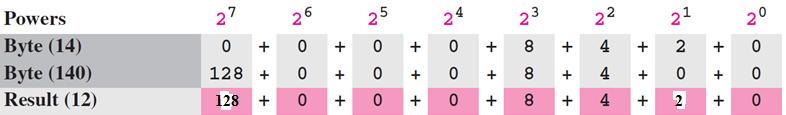
96 Figure Finding a network address using the default mask If bit is ANDed with 1, it s preserved If bit is ANDed with 0, it s changed to a 0. A simple way to determine the netid for un-subnetted cases: (1) if mask byte is 255, retain corresponding byte of the address, (2) if mask byte is 0, set corresponding address byte to 0. 96
97 Example 12 A router receives a packet with the destination address Show how the router finds the network address of the packet. Solution Since the class of the address is B, we assume that the router applies the default mask for class B, to find the network address. 97

98 Recall IP Addresses: Classful Addressing Class # of addresses Percent of the Space A 2 31 = % B 2 30 = % C 2 29 = % D 2 28 = % E 2 28 = % 98
99 5-bit Address Space Illustration No Netid case 32 addresses/block Number of blocks: 1 Address range per block: 0 to 31 Netids: N/A Network Addresses : Broadcast Addresses:
100 5-bit Address Space Illustration 1-bit Netid case 16 addresses/block Number of blocks: 2 Address range per block: 0 to 15 Netids: 0, 1 Network Addresses : 00000, Broadcast Addresses: 01111,
101 5-bit Address Space Illustration 2-bit Netid Case 8 addresses/block Number of blocks: 4 Address range per block: 0 to 7 Netids: 00, 01, 10, 11 Network Addresses : 00000, 01000, 10000, Broadcast Addresses: 00111, 01111, 10111,
102 5-bit Address Space Illustration 3-bit Netid Case 4 addresses/block Number of blocks: 8 Address range per block: 0 to 3 Netids: 000, 001, 010, 011, 100, 101, 110, 111 Network Addresses : 00000, 00100, 01000, , 10100, 11000, Broadcast Addresses: 00011, 00111, 01011, , 10111, 11011,
103 Mixing 3-bit & 2-bit Cases 4 addresses/block and 8 addresses/block Number of blocks: 6 Address range per block: 0 to 3 and 0 to 7 Netids: 000, 001, 010, 011, 10, 11 Network Addresses : 00000, 00100, 01000, , Broadcast Addresses: 00011, 00111, 01011, ,

104 Subnetting When we talked about CLASSFUL addressing we realized the problem of wasted host addresses and depleting available network addresses. In subnetting, a network is divided into several smaller networks called subnetworks or subnets each subnet will have it s own address Typically, there are 2 steps in reaching a destination: first we must reach the network (netid) and then we reach the destination (hostid) 104

105 A network with two levels of hierarchy (not subnetting) The 2 level approach is not enough some times you can only have 1 physical network in example, all host are at the same level no grouping 105
")
106 A network with three levels of hierarchy (subnetted) 106

107 Addresses in a network with and without subnetting With subnetting, there are 3 levels (versus 2 levels). Partition the hostid space into subnetid and hostid. (1 st ) network, (2 nd ) subnetwork and (3 rd ) host 107

108 Figure Network mask and subnetwork mask 108
109 Similar to Hierarchy concept in a telephone number 109
110 Default mask and subnet mask 110
111 Example 13 A class B network can be divided into four subnetworks. The value of n = 16 and the value of n 1 = n 2 = n 3 = n 4 = 16 + log 2 4 = 18. This means that the subnet mask has eighteen 1s and fourteen 0s. In other words, the subnet mask is which is different from the network mask for class B ( ). 111
112 Example 14 A class B network is divided into four subnets. Since one of the addresses in subnet 2 is , we can find the subnet address as: The values of the first, second, and fourth bytes are calculated using the first short cut for AND operation. The value of the third byte is calculated using the second short cut for the AND operation. 112

113 Example 15 What is the subnetwork address if the destination address is and the subnet mask is ? Solution Address: Mask: AND: The subnetwork address is
114 Recall - 5-bit Address Space Illustration 1-bit Netid case (no subnets) 16 addresses/block Number of blocks: 2 Address range per block: 0 to 15 Netids: 0, 1 Network Addresses : 00000, Broadcast Addresses: 01111,
115 5-bit Address Space Illustration 1-bit Subnet case Number of blocks/networks: 2 Number subnets per block: 2 8 addresses/subnet Address range per subnet: 0 to 7 Subnet ids: 0, 1 Network Addresses : 00000, 01000, 10000, Broadcast Addresses: 00111, 01111, 10111,
116 5-bit Address Space Illustration 2-bit Subnet case Number of blocks/networks: 2 Number subnets per block: 4 4 addresses/subnet Address range per subnet: 0 to 3 Subnet ids: 00, 01, 10, 11 Network Addresses : 00000, 00100, 01000, , 10100, 11000, Broadcast Addresses: 00011, 00111, 01011, , 10111, 11011,
117 Illustrating the mask concept (1 of 3) What is the mask?
118 Illustrating the mask concept (2 of 3) What is the mask (subnet mask)?
119 Illustrating the mask concept (3 of 3) What is the mask (subnet mask)?

120 The number of subnets must be a power of 2. Determine the number of subnets added by looking at the number of 1s added to the default mask and performing 2 raised to that number For example, 2 3 = 8 subnets 120
121 Example 16 A company is granted the site address (class C). The company needs six subnets. Design the subnets. Solution The number of 1s in the default mask is 24 (class C). The company needs six subnets. This number 6 is not a power of 2. The next number that is a power of 2 is 8 (2 3 ). We need 3 more 1s in the subnet mask. The total number of 1s in the subnet mask is 27 (=24 + 3). The total number of 0s is 5 (=32-27). The mask would be 121
122 Example 16 Solution (Continued) or The number of subnets is 8. The number of addresses in each subnet is 2 5 (5 is the number of 0s) or

123 Example 16 (Solution Continued) 123
124 Example 17 A company is granted the site address (class B). The company needs 1000 subnets. Design the subnets. Solution The number of 1s in the default mask is 16 (class B). The company needs 1000 subnets. This number is not a power of 2. The next number that is a power of 2 is 1024 (2 10 ). We need 10 more 1s in the subnet mask. The total number of 1s in the subnet mask is 26 (= ). The total number of 0s is 6 (=32-26). The mask is or The number of subnets is The number of addresses in each subnet is 2 6 (6 is the number of 0s) or

125 Example 17 (Solution Continued) Subtract 63 from 255 to get
126 Subnets IP address: subnet part - high order bits host part - low order bits what s a subnet? device interfaces with same subnet part of IP address can physically reach each other without intervening router subnet network consisting of 3 subnets 126
127 Supernetting Although class A and B addresses are dwindling there are plenty of class C addresses The problem with C addresses is, they only have 256 hostids not enough for any midsize to large size organization especially if you plan to give every computer, printer, scanner, etc. multiple IP addresses Supernetting allows an organization the ability to combine several class C blocks in creating a larger range of addresses Note: breaking up a network = subnetting Note: combining Class-C networks = supernetting 127
128 Assigning or Choosing Class C Blocks When assigning class C block, the choices of blocks need to follow a set of rules: #1 the # of blocks must be a power of 2 #2 blocks must be contiguous (no gaps between blocks) #3 the 3 rd byte of the first address in the superblock must be evenly divisible by the number of blocks ie. if the # of blocks is N, the 3 rd byte must be divisible by N 128
129 Example 18 A company needs 600 addresses. Which of the following set of class C blocks can be used to form a supernet for this company? a b c d Solution a: No, there are only three blocks. Must be a power of 2 b: No, the blocks are not contiguous. c: No, 31 in the first block is not divisible by 4. d: Yes, all three requirements are fulfilled. (1. Power of 2, 2. Contiguous and 3. 3 rd byte of 1 st address is divisible by 4: 32/4=8) 129
130 Example 19 A supernet has a first address of and a supernet mask of How many blocks are in this supernet and what is the range of addresses? Solution The default mask has 24 1s because is a class C. Because the supernet mask is , the supernet has 21 1s. Since the difference between the default and supernet masks is 3, there are 2 3 or 8 blocks in this supernet. Because the blocks start with and must be contiguous, the blocks are , , The first address is The last address is The total number of addresses is 8 x 256 =
131 Explain Supernetting Conceptually Back out this bit from netid into host id Causes these 2 blocks to combine as a single block
132 Figure Comparison of subnet, default, and supernet mask 132
133 Classless Addressing Variable-length blocks are used that belong to no classes. 133
134 Figure Variable-length blocks in classless addressing the number of addresses in a block; it must be a power of 2 (2 0, 2 1, 2 2, 2 3,...). 134

135 Figure Prefix and suffix In classless addressing, the prefix defines the network and the suffix defines the host. 135
136 Example 20 What is the prefix length and suffix length if the whole Internet is considered as one single block with 4,294,967,296 addresses? Solution In this case, the prefix length is 0 and the suffix length is 32. All 32 bits vary to define 2 32 = 4,294,967,296 hosts in this single block. 136
137 Example 21 What is the prefix length and suffix length if the Internet is divided into 4,294,967,296 blocks and each block has one single address? Solution In this case, the prefix length for each block is 32 and the suffix length is 0. All 32 bits are needed to define 2 32 = 4,294,967,296 blocks. The only address in each block is defined by the block itself. 137
138 Figure Slash notation The number of addresses in a block is inversely related to the value of the prefix length, n. A small n means a larger block; a large n means a small block. 138
139 Example 22 The following addresses are defined using slash notations. a. In the address /8, the network mask is The mask has eight 1s and twenty-four 0s. The prefix length is 8; the suffix length is 24. b. In the address /16, the network mask is The mask has sixteen 1s and sixteen 0s.The prefix length is 16; the suffix length is 16. c. In the address /27, the network mask is The mask has twenty-seven 1s and five 0s. The prefix length is 27; the suffix length is
140 Extracting Block Information Given an addresses using slash notations: a. The number of addresses in the block: N = n b. First address: (the given address) AND (network mask) c. Last address: (the given address) OR [NOT (network mask)] 140
141 Example 23 One of the addresses in a block is /27. Find the number of addresses in the network, the first address, and the last address. Solution The value of n is 27. The network mask has twenty-seven 1s and five 0s. It is a. The number of addresses in the network is 2 32 n = 32. b. We use the AND operation to find the first address (network address). The first address is /
142 Example 23 Continued c. To find the last address, we first find the complement of the network mask and then OR it with the given address: The last address is /
143 Example 24 One of the addresses in a block is /24. Find the number of addresses, the first address, and the last address in the block. Solution The network mask is a. The number of addresses in the network is = 256. b. To find the first address, we use the short cut methods discussed early in the chapter. The first address is /
144 Example 24 Continued c. To find the last address, we use the complement of the network mask and the first short cut method we discussed before. The last address is /

145 Example 25 One of the addresses in a block is /20. Find the number of addresses, the first address, and the last address in the block. Solution The network mask is a. The number of addresses in the network is = b. To find the first address, we apply the first short cut to bytes 1, 2, and 4 and the second short cut to byte 3. The first address is /
146 Example 25 Continued c. To find the last address, we apply the first short cut to bytes 1, 2, and 4 and the second short cut to byte 3. The OR operation is applied to the complement of the mask. The last address is /
147 Block Allocation Three restrictions needed to be applied to the allocated block: a. The number of requested addresses, N, needs to be a power of 2. b. The value of prefix length, n, can be found from the number of addresses in the block. n = 32 log 2 N c. The beginning address needs to be divisible by the number of addresses of the block. For example, if a block contains 4 addresses, the beginning address must be divisible by 4. If the block has less than 256 addresses, we need to check only the rightmost byte. If it has less than 65,536 addresses, we need to check only the two rightmost bytes, and so on 147
148 Example 26 Which of the following can be the beginning address of a block that contains 16 addresses? a b c d Solution The address is eligible because 32 is divisible by 16. The address is eligible because 80 is divisible by
149 Example 27 Which of the following can be the beginning address of a block that contains 1024 addresses? a b c d Solution To be divisible by 1024, the rightmost byte of an address should be 0 because any value in that first byte will be a fraction of 1024 (ie. 0 to 255). To be divisible by 1024, the rightmost byte should be 0 and the second rightmost byte must be divisible by 4 because for every unique number in the second byte position, there exist 256 addresses in the first byte position that maps to it. To get 1024 addresses overall, you will need an increment of 4 in the 2 nd byte position. Therefore, the 2 nd byte needs to be divisible by 4. Only the address meets this condition. 149
150 150
151 Example Subnetting An organization is granted the block /26. The organization needs four subnetworks, each with an equal number of hosts. Design the subnetworks and find the information about each network. Solution The number of addresses for the whole network can be found as N = = 64. The first address in the network is /26 and the last address is /26. We now design the subnetworks: 1. We grant 16 addresses for each subnetwork to meet the first requirement (64/16 is a power of 2). 2. The subnetwork mask for each subnetwork is: 151
152 Example 28 Continued 3. We grant 16 addresses to each subnet starting from the first available address. The following Figure shows the subblock for each subnet. Note that the starting address in each subnetwork is divisible by the number of addresses in that subnetwork. 152

153 Figure Solution to Example
154 Example 29 An organization is granted a block of addresses with the beginning address /24. The organization needs to have 3 subblocks of addresses to use in its three subnets as shown below: One subblock of 120 addresses. One subblock of 60 addresses. One subblock of 10 addresses. Solution There are = 256 addresses in this block. The first address is /24; the last address is /24. a. The number of addresses in the first subblock is not a power of 2. We allocate 128 addresses. The subnet mask is 25. The first address is /25; the last address is /
155 Example 29 Continued b. The number of addresses in the second subblock is not a power of 2 either. We allocate 64 addresses. The subnet mask is 26. The first address in this block is /26; the last address is /26. c. The number of addresses in the third subblock is not a power of 2 either. We allocate 16 addresses. The subnet mask is 28. The first address in this block is /28; the last address is /28. d. If we add all addresses in the previous subblocks, the result is 208 addresses, which means 48 addresses are left in reserve. The first address in this range is The last address is e. Figure 5.31 shows the configuration of blocks. We have shown the first address in each block. 155

156 Figure Solution to Example
157 Example 30 Assume a company has three offices: Central, East, and West. The Central office is connected to the East and West offices via private, WAN lines. The company is granted a block of 64 addresses with the beginning address /26. The management has decided to allocate 32 addresses for the Central office and divides the rest of addresses between the two other offices. 1. The number of addresses are assigned as follows: 2. We can find the prefix length for each subnetwork: 157
158 Example 30 Continued 3. Figure 5.32 shows the configuration designed by the management. The Central office uses addresses /27 to /27. The company has used three of these addresses for the routers and has reserved the last address in the subblock. The East office uses the addresses /28 to /28. One of these addresses is used for the router and the company has reserved the last address in the subblock. The West office uses the addresses /28 to /28. One of these addresses is used for the router and the company has reserved the last address in the subblock. The company uses no address for the point-to-point connections in WANs. 158

159 Figure Example
160 Example Supernetting An ISP is granted a block of addresses starting with /16 (65,536 addresses). The ISP needs to distribute these addresses to three groups of customers as follows: The first group has 64 customers; each needs approximately 256 addresses. The second group has 128 customers; each needs approximately 128 addresses. The third group has 128 customers; each needs approximately 64 addresses. We design the subblocks and find out how many addresses are still available after these allocations. 160
161 Example 31 Continued Solution Let us solve the problem in two steps. In the first step, we allocate a subblock of addresses to each group. The total number of addresses allocated to each group and the prefix length for each subblock can found as Figure 5.33 shows the design for the first hierarchical level. Figure 5.34 shows the second level of the hierarchy. Note that we have used the first address for each customer as the subnet address and have reserved the last address as a special address. 161

162 Figure Solution to Example 31: first step 162

163 Figure Solution to Example 31: second step 163
164 Special Addresses In classful addressing some addresses were reserved for special purposes. The classless addressing scheme inherits some of these special addresses from classful addressing. 164
165 Special Blocks All-Zeros Address All-Ones Address: Limited Broadcast Address Loopback Addresses Private Addresses Multicast Addresses 165

166 Figure Example of using the all-zeros address Source: Destination: Packet An address of all 0 s is used during bootstrap time if the host doesn t know it s IP address. The un-named host sends an all 0 source address and limited broadcast (all 1 s) destination address to the bootstrap server (DHCP server). 166


167 Figure Example of limited broadcast (all-ones) address Network / / / /24 An host want to send a message to every other host The broadcast are confined to the local network 167


168 Example of this host on this address IP-less Host sending message to bootstrap server An address of all 0 s is used during bootstrap time if the host doesn t know it s IP address. The un-named host sends an all 0 source address and limited broadcast (all 1 s) destination address to the bootstrap server. Example of specific host on this network Host sending to some other specific host on a network An address with a netid of all 0 s is used by a host or router to send another host with in the same network a message. 168

169 Figure Example of loopback address The IP address with the 1 st byte equal to 127 ( ) is used for the loop back address. Loopback address is used to test software on a machine the packet never leaves the machine it returns to the protocol software Example: a ping command can send a packet with a loopback address as the destination address to see if the IP software is capable of receiving and processing a packet. 169

170 Private addresses: They are not recognized globally. Multicast addresses: /4 is reserved for multicast communication. 170


171 Figure Example of a directed broadcast address Network: / / / / /24 Packet 171


172 Example of direct broadcast address Router sending to all hosts on a network If the hostid is all 1 s, it s called a broadcast address and the router use it to send a packet to all host in a specific network. In this case, hosts 20, 64, 126 and etc. will receive the packet from the router Example of limited broadcast address Host sending to all other hosts on a network If the hostid and netid are all 1 s, it s called a limited broadcast address. If the host wants to send a packet to all host in a specific network, it would use this address. The router would block this address so that data stays contained within a specific network. 172
173 IP addresses: how to get one? Q: How does a host get IP address? The IP address of the computer The subnet mask of the computer The IP address of a router The IP address of a name server hard-coded by system admin in a file Windows: control-panel->network->configuration- >tcp/ip->properties UNIX: /etc/rc.config DHCP: Dynamic Host Configuration Protocol: dynamically get address from as server plug-and-play 173
174 DHCP: Dynamic Host Configuration Protocol goal: allow host to dynamically obtain its IP address from network server when it joins network can renew its lease on address in use allows reuse of addresses (only hold address while connected/ on ) support for mobile users who want to join network (more shortly) DHCP overview: host broadcasts DHCP discover msg [optional] DHCP server responds with DHCP offer msg [optional] host requests IP address: DHCP request msg DHCP server sends address: DHCP ack msg 174
175 DHCP client-server scenario / DHCP server arriving DHCP client needs address in this network / /24 175
176 DHCP client-server scenario DHCP server: DHCP discover src : , 68 dest.: ,67 yiaddr: transaction ID: 654 Broadcast: is there a DHCP server out there? arriving client DHCP request DHCP offer src: , 68 dest:: , 67 yiaddrr: transaction that IP address! ID: 655 lifetime: 3600 secs Broadcast: OK. I ll take src: , 67 dest: , 68 yiaddrr: transaction ID: 654 lifetime: 3600 secs Broadcast: I m a DHCP server! Here s an IP address you can use DHCP ACK src: , 67 dest: , 68 yiaddrr: transaction ID: 655 lifetime: 3600 secs Broadcast: OK. You ve got that IP address! 176
177 DHCP: more than IP addresses DHCP can return more than just allocated IP address on subnet: address of first-hop router for client name and IP address of DNS sever network mask (indicating network versus host portion of address) 177
178 DHCP: example DHCP DHCP DHCP DHCP DHCP DHCP DHCP DHCP DHCP UDP IP Eth Phy DHCP DHCP UDP IP Eth Phy router with DHCP server built into router connecting laptop needs its IP address, addr of first-hop router, addr of DNS server: use DHCP DHCP request encapsulated in UDP, encapsulated in IP, encapsulated in Ethernet Ethernet frame broadcast (dest: FFFFFFFFFFFF) on LAN, received at router running DHCP server Ethernet demuxed to IP demuxed, UDP demuxed to DHCP 178
179 DHCP: example DHCP DHCP DHCP DHCP DHCP DHCP DHCP DHCP DHCP DHCP UDP IP Eth Phy DHCP UDP IP Eth Phy router with DHCP server built into router DHCP server formulates DHCP ACK containing client s IP address, IP address of first-hop router for client, name & IP address of DNS server encapsulation of DHCP server, frame forwarded to client, demuxing up to DHCP at client client now knows its IP address, name and IP address of DSN server, IP address of its first-hop router 179
180 IP addressing: the last word... Q: how does an ISP get block of addresses? A: ICANN: Internet Corporation for Assigned Names and Numbers allocates addresses manages DNS assigns domain names, resolves disputes 180
181 NAT: network address translation rest of Internet local network (e.g., home network) / all datagrams leaving local network have same single source NAT IP address: ,different source port numbers datagrams with source or destination in this network have /24 address for source, destination (as usual) 181
182 NAT: network address translation motivation: local network uses just one IP address as far as outside world is concerned: range of addresses not needed from ISP: just one IP address for all devices can change addresses of devices in local network without notifying outside world can change ISP without changing addresses of devices in local network devices inside local net not explicitly addressable, visible by outside world (a security plus) 182
183 NAT: network address translation implementation: NAT router must: outgoing datagrams: replace (source IP address, port #) of every outgoing datagram to (NAT IP address, new port #)... remote clients/servers will respond using (NAT IP address, new port #) as destination addr remember (in NAT translation table) every (source IP address, port #) to (NAT IP address, new port #) translation pair incoming datagrams: replace (NAT IP address, new port #) in dest fields of every incoming datagram with corresponding (source IP address, port #) stored in NAT table 183
184 NAT: network address translation 2: NAT router changes datagram source addr from , 3345 to , 5001, updates table 2 NAT translation table WAN side addr LAN side addr , , 3345 S: , 5001 D: , S: , 3345 D: , : host sends datagram to , S: , 80 D: , : reply arrives dest. address: , 5001 S: , 80 D: , : NAT router changes datagram dest addr from , 5001 to ,
185 NAT: network address translation 16-bit port-number field: 60,000 simultaneous connections with a single LAN-side address! NAT is controversial: routers should only process up to layer 3 violates end-to-end argument NAT possibility must be taken into account by app designers, e.g., P2P applications address shortage should instead be solved by IPv6 185
186 NAT traversal problem client wants to connect to server with address server address local to LAN (client can t use it as destination addr) only one externally visible NATed address: solution1: statically configure NAT to forward incoming connection requests at given port to server e.g., ( , port 2500) always forwarded to port 2500 client? NAT router
187 NAT traversal problem solution 2: Universal Plug and Play (UPnP) Internet Gateway Device (IGD) Protocol. Allows NATed host to: learn public IP address ( ) add/remove port mappings (with lease times) NAT router IGD i.e., automate static NAT port map configuration 187

188 NAT traversal problem solution 3: relaying (used in Skype) NATed client establishes connection to relay external client connects to relay relay bridges packets between to connections client 2. connection to relay initiated by client 3. relaying established 1. connection to relay initiated by NATed host NAT router
189 Network Layer: outline 1 introduction 2 virtual circuit and datagram networks 3 what s inside a router 4 IP: Internet Protocol datagram format IPv4 addressing ICMP IPv6 5 routing algorithms link state distance vector hierarchical routing 6 routing in the Internet RIP OSPF BGP 7 broadcast and multicast routing 189
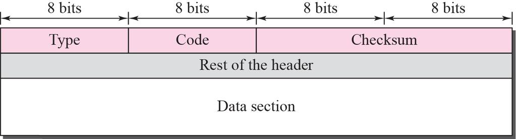
190 ICMP: internet control message protocol used by hosts & routers to communicate networklevel information error reporting: unreachable host, network, port, protocol echo request/reply (used by ping) network-layer above IP: ICMP msgs carried in IP datagrams ICMP message: type, code plus first 8 bytes of IP datagram causing error Type Code description 0 0 echo reply (ping) 3 0 dest. network unreachable 3 1 dest host unreachable 3 2 dest protocol unreachable 3 3 dest port unreachable 3 6 dest network unknown 3 7 dest host unknown 4 0 source quench (congestion control - not used) 8 0 echo request (ping) 9 0 route advertisement 10 0 router discovery 11 0 TTL expired 12 0 bad IP header 190
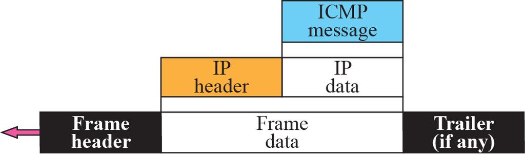
191 ICMP Encapsulation 191
CSE 3214: Computer Network Protocols and Applications Network Layer
 CSE 314: Computer Network Protocols and Applications Network Layer Dr. Peter Lian, Professor Department of Computer Science and Engineering York University Email: peterlian@cse.yorku.ca Office: 101C Lassonde
CMPE 150/L : Introduction to Computer Networks. Chen Qian Computer Engineering UCSC Baskin Engineering Lecture 11
 CMPE 150/L : Introduction to Computer Networks Chen Qian Computer Engineering UCSC Baskin Engineering Lecture 11 1 Midterm exam Midterm this Thursday Close book but one-side 8.5"x11" note is allowed (must
CMSC 332 Computer Networks Network Layer
 CMSC 332 Computer Networks Network Layer Professor Szajda CMSC 332: Computer Networks Where in the Stack... CMSC 332: Computer Network 2 Where in the Stack... Application CMSC 332: Computer Network 2 Where
Chapter 4 Network Layer
 Chapter 4 Network Layer Computer Networking: A Top Down Approach Featuring the Internet, 3 rd edition. Jim Kurose, Keith Ross Addison-Wesley, July 2004. Network Layer 4-1 Chapter 4: Network Layer Chapter
Last time. Wireless link-layer. Introduction. Characteristics of wireless links wireless LANs networking. Cellular Internet access
 Last time Wireless link-layer Introduction Wireless hosts, base stations, wireless links Characteristics of wireless links Signal strength, interference, multipath propagation Hidden terminal, signal fading
Chapter 4. Computer Networking: A Top Down Approach 5 th edition. Jim Kurose, Keith Ross Addison-Wesley, sl April 2009.
 Chapter 4 Network Layer A note on the use of these ppt slides: We re making these slides freely available to all (faculty, students, readers). They re in PowerPoint form so you can add, modify, and delete
Chapter 4: network layer
 Chapter 4: network layer chapter goals: understand principles behind network layer services: network layer service models forwarding versus routing how a router works routing (path selection) broadcast,
Lecture 4 - Network Layer. Transport Layer. Outline. Introduction. Notes. Notes. Notes. Notes. Networks and Security. Jacob Aae Mikkelsen
 Lecture 4 - Network Layer Networks and Security Jacob Aae Mikkelsen IMADA September 23, 2013 September 23, 2013 1 / 67 Transport Layer Goals understand principles behind network layer services: network
Data Communication & Networks G Session 7 - Main Theme Networks: Part I Circuit Switching, Packet Switching, The Network Layer
 Data Communication & Networks G22.2262-001 Session 7 - Main Theme Networks: Part I Circuit Switching, Packet Switching, The Network Layer Dr. Jean-Claude Franchitti New York University Computer Science
Chapter 4: network layer. Network service model. Two key network-layer functions. Network layer. Input port functions. Router architecture overview
 Chapter 4: chapter goals: understand principles behind services service models forwarding versus routing how a router works generalized forwarding instantiation, implementation in the Internet 4- Network
CSC 401 Data and Computer Communications Networks
 CSC 401 Data and Computer Communications Networks Network Layer Overview, Router Design, IP Sec 4.1. 4.2 and 4.3 Prof. Lina Battestilli Fall 2017 Chapter 4: Network Layer, Data Plane chapter goals: understand
Chapter 4 Network Layer
 Chapter 4 Network Layer Reti degli Elaboratori Canale AL Prof.ssa Chiara Petrioli a.a. 2014/2015 We thank for the support material Prof. Kurose-Ross All material copyright 1996-2012 J.F Kurose and K.W.
Chapter 4 Network Layer: The Data Plane
 Chapter 4 Network Layer: The Data Plane A note on the use of these Powerpoint slides: We re making these slides freely available to all (faculty, students, readers). They re in PowerPoint form so you see
Computer Networks. Instructor: Niklas Carlsson
 Computer Networks Instructor: Niklas Carlsson Email: niklas.carlsson@liu.se Notes derived from Computer Networking: A Top Down Approach, by Jim Kurose and Keith Ross, Addison-Wesley. The slides are adapted
HW3 and Quiz. P14, P24, P26, P27, P28, P31, P37, P43, P46, P55, due at 3:00pm with both soft and hard copies, 11/11/2013 (Monday) TCP), 20 mins
 TCP), 20 mins") HW3 and Quiz v HW3 (Chapter 3): R1, R2, R5, R6, R7, R8, R15, P14, P24, P26, P27, P28, P31, P37, P43, P46, P55, due at 3:00pm with both soft and hard copies, 11/11/2013 (Monday) v Quiz: 10/30/2013, Wednesday,
HW3 and Quiz v HW3 (Chapter 3): R1, R2, R5, R6, R7, R8, R15, P14, P24, P26, P27, P28, P31, P37, P43, P46, P55, due at 3:00pm with both soft and hard copies, 11/11/2013 (Monday) v Quiz: 10/30/2013, Wednesday,
Network layer overview
 Network layer overview understand principles behind layer services: layer service models forwarding versus rou:ng how a router works rou:ng (path selec:on) broadcast, mul:cast instan:a:on, implementa:on
Network Layer PREPARED BY AHMED ABDEL-RAOUF
 Network Layer PREPARED BY AHMED ABDEL-RAOUF Network layer transport segment from sending to receiving host on sending side encapsulates segments into datagrams on receiving side, delivers segments to transport
TDTS06: computer Networks
 TDTS06: computer Networks Lecturer: Johannes Schmidt The slides are taken from the book s companion Web site with few modifications: Computer Networking: A Top Down Approach 5 th edition. Jim Kurose, Keith
Key Network-Layer Functions
 Network Layer: Routing & Forwarding Instructor: Anirban Mahanti Office: ICT 745 Email: mahanti@cpsc.ucalgary.ca Class Location: ICT 121 Lectures: MWF 12:00 12:50 hours Notes derived from Computer Networking:
Router Architecture Overview
 Chapter 4: r Introduction (forwarding and routing) r Review of queueing theory r Router design and operation r IP: Internet Protocol m IPv4 (datagram format, addressing, ICMP, NAT) m Ipv6 r Generalized
Lecture 8. Network Layer (cont d) Network Layer 1-1
 Network Layer 1-1") Lecture 8 Network Layer (cont d) Network Layer 1-1 Agenda The Network Layer (cont d) What is inside a router Internet Protocol (IP) IPv4 fragmentation and addressing IP Address Classes and Subnets Network
Lecture 8 Network Layer (cont d) Network Layer 1-1 Agenda The Network Layer (cont d) What is inside a router Internet Protocol (IP) IPv4 fragmentation and addressing IP Address Classes and Subnets Network
1-1. Switching Networks (Fall 2010) EE 586 Communication and. October 25, Lecture 24
 EE 586 Communication and. October 25, Lecture 24") EE 586 Communication and Switching Networks (Fall 2010) Lecture 24 October 25, 2010 1-1 Announcements Midterm 1: Mean = 92.2 Stdev = 8 Still grading your programs (sorry about the delay) Network Layer
EE 586 Communication and Switching Networks (Fall 2010) Lecture 24 October 25, 2010 1-1 Announcements Midterm 1: Mean = 92.2 Stdev = 8 Still grading your programs (sorry about the delay) Network Layer
internet technologies and standards
 Institute of Telecommunications Warsaw University of Technology 2015 internet technologies and standards Piotr Gajowniczek Andrzej Bąk Michał Jarociński Network Layer The majority of slides presented in
Lecture 3. The Network Layer (cont d) Network Layer 1-1
 Network Layer 1-1") Lecture 3 The Network Layer (cont d) Network Layer 1-1 Agenda The Network Layer (cont d) What is inside a router? Internet Protocol (IP) IPv4 fragmentation and addressing IP Address Classes and Subnets
Lecture 3 The Network Layer (cont d) Network Layer 1-1 Agenda The Network Layer (cont d) What is inside a router? Internet Protocol (IP) IPv4 fragmentation and addressing IP Address Classes and Subnets
Chapter 4: Network Layer
 Chapter 4: Introduction (forwarding and routing) Review of queueing theory Routing algorithms Link state, Distance Vector Router design and operation IP: Internet Protocol IPv4 (datagram format, addressing,
COMP211 Chapter 4 Network Layer: The Data Plane
 COMP211 Chapter 4 Network Layer: The Data Plane All material copyright 1996-2016 J.F Kurose and K.W. Ross, All Rights Reserved Computer Networking: A Top Down Approach 7 th edition Jim Kurose, Keith Ross
CMPE 150/L : Introduction to Computer Networks. Chen Qian Computer Engineering UCSC Baskin Engineering Lecture 12
 CMPE 150/L : Introduction to Computer Networks Chen Qian Computer Engineering UCSC Baskin Engineering Lecture 12 1 Chapter 4: outline 4.1 introduction 4.2 virtual circuit and datagram networks 4.3 what
Computer Networks Lecture -5- IPv4 Addresses. Dr. Abbas Abdulazeez
 Computer Networks Lecture -5- IPv4 Addresses Dr. Abbas Abdulazeez McGraw-Hill The McGraw-Hill Companies, Inc., 2000 OBJECTIVES: To introduce the concept of an address space in general and the address space
Chapter 4 Network Layer: The Data Plane
 Chapter 4 Network Layer: The Data Plane Chapter 4: outline 4.1 Overview of Network layer data plane control plane 4.2 What s inside a router 4.3 IP: Internet Protocol datagram format fragmentation IPv4
Lecture 7. Network Layer. Network Layer 1-1
 Lecture 7 Network Layer Network Layer 1-1 Agenda Introduction to the Network Layer Network layer functions Service models Network layer connection and connectionless services Introduction to data routing
CSC 4900 Computer Networks: Network Layer
 CSC 4900 Computer Networks: Network Layer Professor Henry Carter Fall 2017 Villanova University Department of Computing Sciences Review What is AIMD? When do we use it? What is the steady state profile
internet technologies and standards
 Institute of Telecommunications Warsaw University of Technology 2017 internet technologies and standards Piotr Gajowniczek Andrzej Bąk Michał Jarociński Network Layer The majority of slides presented in
Lecture 16: Network Layer Overview, Internet Protocol
 Lecture 16: Network Layer Overview, Internet Protocol COMP 332, Spring 2018 Victoria Manfredi Acknowledgements: materials adapted from Computer Networking: A Top Down Approach 7 th edition: 1996-2016,
CSCE 463/612 Networks and Distributed Processing Spring 2018
 CSCE 463/612 Networks and Distributed Processing Spring 2018 Network Layer II Dmitri Loguinov Texas A&M University April 3, 2018 Original slides copyright 1996-2004 J.F Kurose and K.W. Ross 1 Chapter 4:
Network Layer: Control/data plane, addressing, routers
 Network Layer: Control/data plane, addressing, routers CS 352, Lecture 10 http://www.cs.rutgers.edu/~sn624/352-s19 Srinivas Narayana (heavily adapted from slides by Prof. Badri Nath and the textbook authors)
Chapter 4 Network Layer: The Data Plane. Part A. Computer Networking: A Top Down Approach
 Chapter 4 Network Layer: The Data Plane Part A All material copyright 996-06 J.F Kurose and K.W. Ross, All Rights Reserved Computer Networking: A Top Down Approach 7 th Edition, Global Edition Jim Kurose,
Topic 4a Router Operation and Scheduling. Ch4: Network Layer: The Data Plane. Computer Networking: A Top Down Approach
 Topic 4a Router Operation and Scheduling Ch4: Network Layer: The Data Plane Computer Networking: A Top Down Approach 7 th edition Jim Kurose, Keith Ross Pearson/Addison Wesley April 2016 4-1 Chapter 4:
Communication Networks ( ) / Fall 2013 The Blavatnik School of Computer Science, Tel-Aviv University. Allon Wagner
 / Fall 2013 The Blavatnik School of Computer Science, Tel-Aviv University. Allon Wagner") Communication Networks (0368-3030) / Fall 2013 The Blavatnik School of Computer Science, Tel-Aviv University Allon Wagner Kurose & Ross, Chapter 4 (5 th ed.) Many slides adapted from: J. Kurose & K. Ross
Communication Networks (0368-3030) / Fall 2013 The Blavatnik School of Computer Science, Tel-Aviv University Allon Wagner Kurose & Ross, Chapter 4 (5 th ed.) Many slides adapted from: J. Kurose & K. Ross
CSCI Computer Networks Fall 2016
 source: computer-s-webdesign.com CSCI 4760 - Computer Networks Fall 2016 Instructor: Prof. Roberto Perdisci perdisci@cs.uga.edu These slides are adapted from the textbook slides by J.F. Kurose and K.W.
Network Layer: Router Architecture, IP Addressing
 Network Layer: Router Architecture, IP Addressing UG3 Computer Communications & Networks (COMN) Mahesh Marina mahesh@ed.ac.uk Slides thanks to Myungjin Lee and copyright of Kurose and Ross Router Architecture
Chapter 4 Network Layer
 Chapter 4 Network Layer Computer Networking A Top-Down Approach These slides are based on the slides made available by Kurose and Ross. All material copyright 1996-2012 J.F Kurose and K.W. Ross, All Rights
Figure 11 Two-level addressing in classful addressing
 Two-Level Addressing The whole purpose of IPv4 addressing is to define a destination for an Internet packet (at the network layer). When classful addressing was designed, it was assumed that the whole
Network Layer/IP Protocols
 Network Layer/IP Protocols 1 Outline IP Datagram (IPv4) NAT Connection less and connection oriented service 2 IPv4 packet header 3 IPv4 Datagram Header Format version of the IP protocol (4 BIts) IP header
NETWORK LAYER: IP Addressing
 NETWORK LAYER: IP Addressing McGraw-Hill The McGraw-Hill Companies, Inc., 2004 2000 Position of network layer McGraw-Hill The McGraw-Hill Companies, Inc., 2004 Network layer duties McGraw-Hill The McGraw-Hill
Routers. Session 12 INST 346 Technologies, Infrastructure and Architecture
 Routers Session 12 INST 346 Technologies, Infrastructure and Architecture Goals for Today Finish up TCP Flow control, timeout selection, close connection Network layer overview Structure of a router Getahead:
Network Layer: Data Plane 4-2
 Network Layer: Data Plane EECS3214 18-02-25 4-1 Chapter 4: outline 4.1 Overview of Network layer data plane control plane 4.2 What s inside a router 4.3 IP: Internet Protocol datagram format fragmentation
NETWORK LAYER DATA PLANE
 NETWORK LAYER DATA PLANE 1 GOALS Understand principles behind network layer services, focusing on the data plane: Network layer service models Forwarding versus routing How a router works Generalized forwarding
CS 3516: Advanced Computer Networks
 Welcome to CS 3516: Advanced Computer Networks Prof. Yanhua Li Time: 9:00am 9:50am M, T, R, and F Location: Fuller 320 Fall 2017 A-term 1 Some slides are originally from the course materials of the textbook
Chapter 19 Network Layer: Logical Addressing
 Chapter 19 Network Layer: Logical Addressing 19.1 Copyright The McGraw-Hill Companies, Inc. Permission required for reproduction or display. 19.2 19-1 IPv4 ADDRESSES An IPv4 address is a 32-bit address
Lecture 8 Network Layer: Logical addressing
 Data Communications ACOE412 Lecture 8 Network Layer: Logical addressing Spring 2009 1 0. Overview In this lecture we will cover the following topics: 14.Network Layer: Logical addressing 14.1 IPv4 Addresses
Chapter 4 Network Layer
 Chapter 4 Network Layer These slides are adapted from the original slides provided by J.Kurose and K.W Ross. All material copyright 1996-2012 J.F Kurose and K.W. Ross, All Rights Reserved Computer Networking:
Chapter 4 Network Layer
 Chapter 4 Network Layer A note on the use of these ppt slides: We re making these slides freely available to all (faculty, students, readers). They re in PowerPoint form so you see the animations; and
Chapter 4 Network Layer: The Data Plane
 Chapter 4 Network Layer: The Data Plane Lu Su Assistant Professor Department of Computer Science and Engineering State University of New York at Buffalo Adapted from the slides of the book s authors Computer
Course on Computer Communication and Networks. Lecture 6 Network Layer part 1: Data Plane Chapter 4 (7/e) (6/e Ch4-first part)
 (6/e Ch4-first part)") Course on Computer Communication and Networks Lecture 6 Network Layer part 1: Data Plane Chapter 4 (7/e) (6/e Ch4-first part) EDA344/DIT 423, CTH/GU Based on the book Computer Networking: A Top Down Approach,
Course on Computer Communication and Networks Lecture 6 Network Layer part 1: Data Plane Chapter 4 (7/e) (6/e Ch4-first part) EDA344/DIT 423, CTH/GU Based on the book Computer Networking: A Top Down Approach,
The Network Layer Forwarding Tables and Switching Fabric
 The Network Layer Forwarding Tables and Switching Fabric Smith College, CSC 249 February 27, 2018 1 Network Layer Overview q Network layer services v v Desired services and tasks Actual services and tasks
EC441 Fall 2018 Introduction to Computer Networking Chapter4: Network Layer Data Plane
 EC441 Fall 2018 Introduction to Computer Networking Chapter4: Network Layer Data Plane This presentation is adapted from slides produced by Jim Kurose and Keith Ross for their book, Computer Networking:
EITF25 Internet Techniques and Applications L7: Internet. Stefan Höst
 EITF25 Internet Techniques and Applications L7: Internet Stefan Höst What is Internet? Internet consists of a number of networks that exchange data according to traffic agreements. All networks in Internet
The Network Layer and Routers
 The Network Layer and Routers Daniel Zappala CS 460 Computer Networking Brigham Young University 2/18 Network Layer deliver packets from sending host to receiving host must be on every host, router in
IP Addresses McGraw-Hill The McGraw-Hill Companies, Inc., 2000
 IP Addresses The IP addresses are unique. An IPv4 address is a 32-bit address. An IPv6 address is a 128-bit address. The address space of IPv4 is 2 32 or 4,294,967,296. The address space of IPv6 is 2 128
Chapter 5. Subnetting/Supernetting and Classless Addressing
 Chapter 5 Subnetting/Supernetting and Classless Addressing Outline Subnetting Supernernetting Classless addressing 5.1 SUBNETTING Subnetting IP addresses are designed with two level of hierarchy Two levels
Chapter 18. Introduction to Network Layer
 Chapter 18. Introduction to Network Layer 18.1 Network Layer Services 18.2 Packet Switching 18.3 Network Layer Performance 18.4 IPv4 Addresses 18.5 Forwarding of IP Packets Computer Networks 18-1 Communication
Chapter 4 Network Layer
 Chapter 4 Network Layer A note on the use of these ppt slides: We re making these slides freely available to all (faculty, students, readers). They re in PowerPoint form so you see the animations; and
Data Communications & Networks. Session 7 Main Theme Networks: Part I Circuit Switching, Packet Switching, The Network Layer
 Data Communications & Networks Session 7 Main Theme Networks: Part I Circuit Switching, Packet Switching, The Network Layer Dr. Jean-Claude Franchitti New York University Computer Science Department Courant
Chapter 4 Network Layer
 Sungkyunkwan University Chapter 4 Network Layer Prepared by H. Choo 2018-Fall Computer Networks Copyright 2000-2014 2000-2018 Networking Laboratory 1/52 Presentation Outline 4.1 Introduction 4.2 Network-Layer
CC231 Introduction to Networks Dr. Ayman A. Abdel-Hamid. Internet Protocol Suite
 CC231 Introduction to Networks Dr. Ayman A. Abdel-Hamid College of Computing and Information Technology Arab bacademy for Science &T Technology and Maritime Transport Internet Protocol Suite IP Suite Dr.
Last time. BGP policy. Broadcast / multicast routing. Link virtualization. Spanning trees. Reverse path forwarding, pruning Tunneling
 Last time BGP policy Broadcast / multicast routing Spanning trees Source-based, group-shared, center-based Reverse path forwarding, pruning Tunneling Link virtualization Whole networks can act as an Internet
Subnetting/Supernetting and Classless Addressing
 Subnetting/Supernetting and Classless Addressing CONTENTS SUBNETTING SUPERNETTING CLASSLESS ADDRSSING 5.1 SUBNETTING IP addresses are designed with two levels of hierarchy. Figure 5-1 A network with two
Introduction to Computer Networking. Guy Leduc. Chapter 4 Network Layer: The Data Plane. Chapter 4: Network Layer Data Plane
 Introduction to Computer Networking Guy Leduc Chapter 4 Network Layer: The Data Plane Computer Networking: A Top Down Approach, 7 th edition. Jim Kurose, Keith Ross Addison-Wesley, April 2016. From Computer
Master Course Computer Networks IN2097
 Chair for Network Architectures and Services Prof. Carle Department for Computer Science TU München Master Course Computer Networks IN2097 Prof. Dr.-Ing. Georg Carle Christian Grothoff, Ph.D. Chair for
ECE 158A: Lecture 7. Fall 2015
 ECE 158A: Lecture 7 Fall 2015 Outline We have discussed IP shortest path routing Now we have a closer look at the IP addressing mechanism We are still at the networking layer, we will examine: IP Headers
Quiz. Segment structure and fields Flow control (rwnd) Timeout interval. Phases transition ssthresh setting Cwnd setting
 Timeout interval. Phases transition ssthresh setting Cwnd setting") Quiz v 10/30/2013 (Wednesday), 20 mins v Midterm question (available on website) v TCP basics Segment structure and fields Flow control (rwnd) Timeout interval v TCP Congestion control Phases transition
Quiz v 10/30/2013 (Wednesday), 20 mins v Midterm question (available on website) v TCP basics Segment structure and fields Flow control (rwnd) Timeout interval v TCP Congestion control Phases transition
Objectives. Note: An IP address is a 32-bit address. The IP addresses are unique. The address space of IPv4 is 2 32 or 4,294,967,296.
 Chapter 4 Objectives Upon completion you will be able to: Understand IPv4 addresses and classes Identify the class of an IP address Find the network address given an IP address Understand masks and how
Chapter 20 Network Layer: Internet Protocol 20.1
 Chapter 20 Network Layer: Internet Protocol 20.1 Copyright The McGraw-Hill Companies, Inc. Permission required for reproduction or display. 20-1 INTERNETWORKING In this section, we discuss internetworking,
McGraw-Hill The McGraw-Hill Companies, Inc., 2000
 !! McGraw-Hill The McGraw-Hill Companies, Inc., 2000 "#$% & '$# )1 ) ) )6 ) )* )- ). )0 )1! )11 )1 )1 )16 )1 3'' 4", ( ( $ ( $ $$+, $$, /+ & 23,4 )/+ &4 $ 53" Network Layer Position of network layer Figure
TSIN02 - Internetworking
 Lecture 2: The Internet Protocol Literature: Forouzan: ch 4-9 and ch 27 2004 Image Coding Group, Linköpings Universitet Outline About the network layer Tasks Addressing Routing Protocols 2 Tasks of the
CSC358 Week 6. Adapted from slides by J.F. Kurose and K. W. Ross. All material copyright J.F Kurose and K.W. Ross, All Rights Reserved
 CSC358 Week 6 Adapted from slides by J.F. Kurose and K. W. Ross. All material copyright 1996-2016 J.F Kurose and K.W. Ross, All Rights Reserved Logistics Assignment 2 posted, due Feb 24, 10pm Next week
Chapter 4: Network Layer
 Mecanismes d Echange d Informations Chapter 4 Network Layer A note on the use of these ppt slides: We re making these slides freely available to all (faculty, students, readers). They re in PowerPoint
Chapter 4 Network Layer: The Data Plane
 Chapter 4 Network Layer: The Data Plane A note on the use of these Powerpoint slides: We re making these slides freely available to all (faculty, students, readers). They re in PowerPoint form so you see
CS 3516: Computer Networks
 Welcome to CS 3516: Computer Networks Prof. Yanhua Li Time: 9:00am 9:50am M, T, R, and F Location: AK 219 Fall 2018 A-term 1 Some slides are originally from the course materials of the textbook Computer
Internet Fundamentals
 Internet Fundamentals Lecture-10 IPv4 19.2 19-1 IPv4 ADDRESSES An IPv4 address is a 32-bit address that uniquely and universally defines the connection of a device (for example, a computer or a router)
CSCE 463/612 Networks and Distributed Processing Spring 2018
 CSCE 463/612 Networks and Distributed Processing Spring 2018 Network Layer Dmitri Loguinov Texas A&M University March 29, 2018 Original slides copyright 1996-2004 J.F Kurose and K.W. Ross 1 Homework #3
CPSC 826 Internetworking. The Network Layer: Routing & Addressing Outline. The Network Layer
 1 CPSC 826 Intering The Network Layer: Routing & Addressing Outline The Network Layer Michele Weigle Department of Computer Science Clemson University mweigle@cs.clemson.edu November 10, 2004 Network layer
Position of IP and other network-layer protocols in TCP/IP protocol suite
 Position of IP and other network-layer protocols in TCP/IP protocol suite IPv4 is an unreliable datagram protocol a best-effort delivery service. The term best-effort means that IPv4 packets can be corrupted,
Chapter 06 IP Address
 Chapter 06 IP Address IP Address Internet address Identifier used at IP layer 32 bit binary address The address space of IPv4 is 2 32 or 4,294,967,296 Consists of netid and hosted IP Address Structure
Network Layer: Chapter 4. The Data Plane. Computer Networking: A Top Down Approach
 Chapter 4 Network Layer: The Data Plane A note on the use of these Powerpoint slides: We re making these slides freely available to all (faculty, students, readers). They re in PowerPoint form so you see
UNIT III THE NETWORK LAYER
 UNIT III THE NETWORK LAYER Introduction-Virtual Circuit and Datagram Networks- Inside a Router- The Internet Protocol (IP): Forwarding and Addressing in the Internet-Routing Algorithms Routing in the Internet-Broadcast
Chapter 4 Network Layer: The Data Plane
 Chapter 4 Network Layer: The Data Plane A note on the use of these Powerpoint slides: We re making these slides freely available to all (faculty, students, readers). They re in PowerPoint form so you see
Chapter 4 Network Layer: The Data Plane
 Chapter 4 Network Layer: The Data Plane A note on the use of these Powerpoint slides: We re making these slides freely available to all (faculty, students, readers). They re in PowerPoint form so you see
The Internet Protocol (IP)
") The Internet Protocol (IP) The Blood of the Internet (C) Herbert Haas 2005/03/11 "Information Superhighway is really an acronym for 'Interactive Network For Organizing, Retrieving, Manipulating, Accessing
The Internet Protocol (IP) The Blood of the Internet (C) Herbert Haas 2005/03/11 "Information Superhighway is really an acronym for 'Interactive Network For Organizing, Retrieving, Manipulating, Accessing
Router Architecture Overview
 Router Architecture Overview What s inside a router? Philipp S. Tiesel philipp@inet.tu-berlin.de Slides credits to James Kempf & Anja Feldmann What does a Router Look Like? Ericsson SSR 8020 BNG/BRAS/PGW
IP - The Internet Protocol. Based on the slides of Dr. Jorg Liebeherr, University of Virginia
 IP - The Internet Protocol Based on the slides of Dr. Jorg Liebeherr, University of Virginia Orientation IP (Internet Protocol) is a Network Layer Protocol. IP: The waist of the hourglass IP is the waist
Network Superhighway CSCD 330. Network Programming Winter Lecture 13 Network Layer. Reading: Chapter 4
 CSCD 330 Network Superhighway Network Programming Winter 2015 Lecture 13 Network Layer Reading: Chapter 4 Some slides provided courtesy of J.F Kurose and K.W. Ross, All Rights Reserved, copyright 1996-2007
Chapter 4 Network Layer: The Data Plane
 Chapter 4 Network Layer: The Data Plane A note on the use of these Powerpoint slides: We re making these slides freely available to all (faculty, students, readers). They re in PowerPoint form so you see
CS 43: Computer Networks. 21: The Network Layer & IP November 7, 2018
 CS 43: Computer Networks 21: The Network Layer & IP November 7, 2018 The Network Layer! Application: the application (e.g., the Web, Email) Transport: end-to-end connections, reliability Network: routing
EEC-484/584 Computer Networks
 EEC-484/584 Computer Networks Lecture 13 wenbing@ieee.org (Lecture nodes are based on materials supplied by Dr. Louise Moser at UCSB and Prentice-Hall) Outline 2 Review of lecture 12 Routing Congestion
Network layer: Overview. Network layer functions IP Routing and forwarding NAT ARP IPv6 Routing
 Network layer: Overview Network layer functions IP Routing and forwarding NAT ARP IPv6 Routing 1 Network Layer Functions Transport packet from sending to receiving hosts Network layer protocols in every
Department of Computer and IT Engineering University of Kurdistan. Network Layer. By: Dr. Alireza Abdollahpouri
 Department of Computer and IT Engineering University of Kurdistan Network Layer By: Dr. Alireza Abdollahpouri What s the Internet: nuts and bolts view PC server wireless laptop cellular handheld millions
IPv4 addressing, NAT. Computer Networking: A Top Down Approach 6 th edition Jim Kurose, Keith Ross Addison-Wesley.
 IPv4 addressing, NAT http://xkcd.com/195/ Computer Networking: A Top Down Approach 6 th edition Jim Kurose, Keith Ross Addison-Wesley Some materials copyright 1996-2012 J.F Kurose and K.W. Ross, All Rights
Internet Technology 3/23/2016
 Internet Technology // Network Layer Transport Layer (Layer ) Application-to-application communication Internet Technology Network Layer (Layer ) Host-to-host communication. Network Layer Route Router
Network layer: Overview. Network Layer Functions
 Network layer: Overview Network layer functions IP Routing and forwarding NAT ARP IPv6 Routing 1 Network Layer Functions Transport packet from sending to receiving hosts Network layer protocols in every