UNIT-II Introduction to UML
|
|
|
- Jade Agatha Flynn
- 5 years ago
- Views:
Transcription
1 UNIT-II Introduction to UML - P. P. Mahale
2 UML OVERVIEW OF UML :- We need a Modeling Language! We will use the Unified Modeling Language, UML), Provides a standard for artifacts produced during development (semantic models, syntactic notation, and diagrams: the things that must understood, controlled, and exchanged. The Unified Modeling Language (UML) is a language for Specifying Visualizing Constructing Documenting The UML Provides Standardized Diagrams

3 SCOPE OF UML UML is a language for Specifying Visualizing Constructing Documenting UML is a language:- - Language provide vocabulary & rule for combining words for communication. - Modeling language is a lang. which focus on conceptual & physical representation of a system - Standard language for s/w blueprint - Tell how to create real well formed models.

4 UML is a language for Visualizing - Each symbol in UML is a well-defined semantics


5 UML is a language for Specifying - Building model that are precise, unambiguous, & complete - It address specification of all important analysis, design & implementation


6 UML is a language for constructing - it s model can directly connected to a variety of programming language such as java,c,c++ etc - Mapping permit forward engg: generation of code from a UML model into a programming language. Reverse also possible


7 UML is a language for documenting - Artifact include:- - Requirement - source code - prototypes - Architecture - project plans - release - Design - tests - It express requirements, activities,planning & release management
8 Where Can the UML Be Used? Enterprise information systems Banking and financial services Telecommunications Transportation Defense/aerospace Retail Medical electronics Scientific Distributed Web-based services

9 U M L ~ Unified: Unification of earlier object-oriented analysis and design methods. Same concepts and notation for different application domains and different development processes. Same concepts and notation through the ~ whole development lifecycle. Modeling: Making a semantically* complete abstraction of a system. (* The formal specification of the meaning and behavior of something) ~ Language: A graphical language


10 Deployment Diagrams Use-Case Diagrams Use-Case Diagrams Use-Case Diagrams Scenario Diagrams Scenario Diagrams Sequence Diagrams State Diagrams State Diagrams State Diagrams Component Diagrams Component Diagrams Component Diagrams Models State Diagrams State Diagrams Object Diagrams Scenario Diagrams Scenario Diagrams Collaboration Diagrams Use-Case Diagrams Use-Case Diagrams Activity Diagrams State Diagrams State Diagrams Class Diagrams
11 UML 2.0 New Features Goal:- - provide user with ready-to-use expressive visual modeling language - Support higher level development concept, such as collaboration, framework, pattern, component New diagram include:- - Structure diagram - Composite diagram - Communication diagram - Timing diagram - Interaction overview diagram
12 Significant changes in 2.0 Activity diagrams completely overhauled OMG realized they were being used for business modeling instead of class modeling. Diagrams were made more similar to flowcharts. Package Diagrams added for high level overview of code structure. Collaboration diagrams renamed as communication diagrams but specification remains the same. Timing diagrams added for real-time applications.


13 DIAGRAM STRUCTURE
14 DIAGRAM STRUCTURE DIAGRAM STRUCTURAL BEHAVIORAL STRUCTURAL DIAGRAM PACKAGE DIAGRAM OBJECT DIAGRAM CLASS DIAGRAM DEPLOYMENT DIAGRAM COMPONEN T DIAGRAM COMPOSITE DIAGRAM
15 Behavioral diagram Behavioral DIAGRAM ACTIVITY DIAGRAM INTERACTION DIAGRAM USE-CASE DIAGRAM STATE MACHINE DIAGRAM INTERACTION OVERVIEW DIAGRAM TIMING DIAGRAM COMMUNICATION DIAGRAM SEQUENCE DIAGRAM
16 CONCEPTUAL MODEL OF UML 3 major element 1. UML s basic building block 2. Rule that dictate how those building block may be put together 3. Common mechanism apply through UML 1. UML s basic building block 3 kind of building block 1. Things 2. Relationship 3. Diagrams
17 Things: 4 kind 1. Structural 2. Behavioral 3. Grouping 4. Annotational
18 1. Structural things :- These are the mostly static parts of a model, representing elements that are either conceptual or physical Class: class is a description of a set of objects that share the same attributes, operations, relationships, and semantics. - class implements one or more interfaces. - Graphically, a class is rendered as a rectangle, usually including its name, attributes, and operations
19 Interface :- - it is a collection of operations that specify a service of a class or component. - An interface therefore describes the externally visible behavior of that element. - defines a set of operation specifications but never a set of operation implementations - Graphically, an interface is rendered as a circle together with its name. - it is typically attached to the class or component that realizes the interface
20 Collaboration : - defines an interaction and is a society of roles and other elements that work together to provide some cooperative behavior that's bigger than the sum of all the elements. - have structural, as well as behavioral, dimensions - represent the implementation of patterns that make up a system.
21 Use case : - It is a description of set of sequence of actions that a system performs that yields an observable result of value to a particular actor. - A use case is used to structure the behavioral things in a model.


22 Active class : - It is a class whose objects own one or more processes or threads and therefore can initiate control activity - Graphically, an active class is rendered just like a class, but with heavy lines, usually including its name, attributes, and operations
23 Component - It is a physical and replaceable part of a system that conforms to and provides the realization of a set of interfaces. - A component typically represents the physical packaging of otherwise logical elements, such as classes, interfaces, and collaborations. - Graphically, a component is rendered as a rectangle with tabs, usually including only its name
24 Node - It is a physical element that exists at run time and represents a computational resource, generally having at least some memory and, often, processing capability. - a node is rendered as a cube, usually including only its name
25 2. Behavioral Things - Behavioral things are the dynamic parts of UML models. - representing behavior over time and space Interaction is a behavior that comprises a set of messages exchanged among a set of objects within a particular context to accomplish a specific purpose State machine is a behavior that specifies the sequences of states an object or an interaction goes through during its lifetime in response to events, together with its responses to those events.
26
27 3. Grouping Things Grouping things are the organizational parts of UML models. These are the boxes into which a model can be decomposed Package is a general-purpose mechanism for organizing elements into groups. Structural things, behavioral things, and even other grouping things may be placed in a package - Graphically, a package is rendered as a tabbed folder, usually including only its name and, sometimes, its contents
28 4. Annotational Things Annotational things are the explanatory parts of UML models. These are the comments you may apply to describe, illuminate, and remark about any element in a model Note: - note is simply a symbol for rendering constraints and comments attached to an element or a collection of elements
29 Relationships in the UML Four kinds of relationships in the UML: 1. Dependency 2. Association 3. Generalization 4. Realization
30 1. Dependency is a semantic relationship between two things in which a change to one thing(the independent thing) may affect the semantics of the other thing (the dependent thing). - Graphically, a dependency is rendered as a dashed line, possibly directed, and occasionally including a label
31 2. Association is a structural relationship that describes a set of links, a link being a connection among objects. - Aggregation is a special kind of association
32 3. Generalization - is a specialization/generalization relationship in which objects of the specialized element (the child) are substitutable for objects of the generalized element (the parent). - rendered as a solid line with a hollow arrowhead pointing to the parent
33 4. Realization - is a semantic relationship between classifiers, wherein one classifier specifies a contract that another classifier guarantees to carry out. - Graphically, a realization relationship is rendered as a cross between a generalization and a dependency relationship
34 Aggregation A special form of association that specifies a whole-part relationship between the aggregate (whole) and a component part. Composition A form of aggregation with strong ownership and coincident lifetime as part of the whole.
35
36 Diagrams in the UML 1.Class diagram 8. Component diagram 2. Object diagram 9. Deployment diagram 3. Use case diagram 4. Sequence diagram 5. Collaboration diagram 6. State chart diagram 7. Activity diagram
37 A class diagram shows a set of classes, interfaces, and collaborations and their relationships. An object diagram shows a set of objects and their relationships. A use case diagram shows a set of use cases and actors (a special kind of class) and their relationships. Both sequence diagrams and collaboration diagrams are kinds of interaction diagrams. An shows an interaction, consisting of a set of objects and their relationships, including the messages that may be dispatched among them.
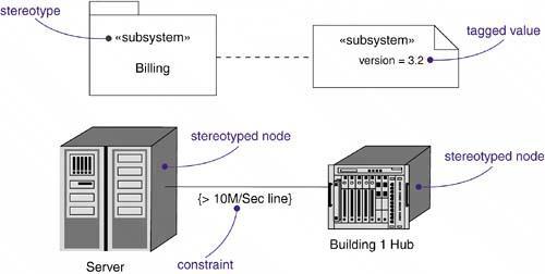
38 A state chart diagram shows a state machine, consisting of states, transitions, events, and activities. An activity diagram is a special kind of a state chart diagram that shows the flow from activity to activity within a system. A component diagram shows the organizations and dependencies among a set of components. A deployment diagram shows the configuration of run-time processing nodes and the components that live on them.
39 Rules of UML UML has a number of rules so that the models are semantically selfconsistent and related to other models in the system harmoniously. UML has semantic rules for the following: 1. Names 2. Scope 3. Visibility 4. Integrity 5. Execution
40 Common Mechanisms in the UML 1. Specifications 2. Adornments 3. Common divisions 4. Extensibility mechanisms
41 1. Specifications UML is more than just a graphical language. Rather, behind every part of its graphical notation. There is a specification that provides a textual statement of the syntax and semantics of that building block. For example, behind a class icon is a specification that provides the full set of attributes, operations (including their full signatures), and behaviors UML's specifications provide a semantic backplane that contains all the parts of all the models of a system, each part related to one another in a consistent fashion. The UML's diagrams are simply visual projections into that backplane, each diagram revealing a specific interesting aspect of the system.

42 2. Adornments Most elements in the UML have a unique and direct graphical notation that provides a visual representation of the most important aspects of the element. - For example, the notation for a class is intentionally designed to be easy to draw exposes the most important aspects of a class, namely its name, attributes, and operations. Every element in the UML's notation starts with a basic symbol, to which can be added a variety of adornments specific to that symbol.
43 3. Common Divisions There is the division of class and object. A class is an abstraction; an object is one concrete manifestation of that abstraction. In the UML you can model classes as well as objects.
44 4. Extensibility Mechanisms UML provides a standard language for writing software blueprints, but it is not possible for one closed language. Allows you to extend the language by adding new building blocks, creating new properties and specifying new semantics. For this reason, the UML is opened-ended, making it possible for you to extend the language in controlled ways. Extensibility mechanisms include 1. Stereotypes 2. Tagged values 3. Constraints
45 1. Stereotypes - Stereotype extends the vocabulary of the UML allowing you to create new kinds of building blocks that are derived from existing ones but that are specific to your problem. You can make exceptions in your models like basic building blocks by marking them with an appropriate stereotype, as for the class Overflow.
46
47 2. Tagged values Tagged value extends the properties of a UML building block, allowing you to create new information in that element's specification. For example, if you are working on a product that undergoes many releases over time, you often want to track the version and author of certain critical abstractions. Version and author are not primitive UML concepts. They can be added to any building block, such as a class, by introducing new tagged values to that building block. class EventQueue is extended by marking its version and author explicitly.
48 3. Constraints Constraint extends the semantics of a UML building block, allowing you to add new rules or modify existing ones. For example, you might want to constrain the EventQueue class so that all additions are done in order. As Figure above shows, you can add a constraint that explicitly marks these for the operation add.
49
50 MAJOR COMPONENT IN UML 2.0 New concept for describing internal architecture & collaboration by mean of port, connector & part Introduction of inheritance of behavior in state machine & encapsulation of sub machine through use of entry & exit point Improve encapsulation of component through complex parts with protocol state machine that control interaction with environment Improvement of specification, realization & wiring aspect of component Interaction of action & activities & use of flow semantics instead of state machine Interaction improved by composition, reference, exception, loop etc

51 Composite state Difficult to specify composite state that can be reused in other state machine UML 2.0 introduces exit & entry point that control access to a composite state
52 ARCHITECTURAL CONCEPTS IN UML Core concept of describing internal structure are part, connector, port 1. PARTS:- - Describe internal structure of a class - Part lives & dies as part of lifetime of an object of containing class 2. PORTS:- - Port describe interaction point for a class, it is addressable i.e. signal can be send to it - Port has interfaces that specifies operation & signal offered by class - Class can send & receive signal via port
53 CONNECTOR:- - It specifies a link that enables communication between two or more parts - It specify link between parts only - It may attached to port on directly to part - Fig. shows engine e:engine in a class car is connected by axle connector to instances in rear: wheel
54
55 STATE MACHINE IN UML 2.0 Major changes in UML Composite state with entry/exit points - State machine generalization that enables inheritance & specification of behavior - State machine diagram is a behavior diagram which shows discrete behavior of a part of designed system through finite state transitions
56 OVERVIEW OF ALL UML 2.0 DIAGRAMS 3 classification of all UML 2.0 diagrams 1. Behavioral diagram:- - Include activity, state, use-case, interaction diagram 2. Interaction diagram:- - communication, Interaction overview, sequence & timing diagram 3. Structure diagram:- - Class, object,composite,component,deployment, package diagram Activity Diagram - Illustrate the dynamic view of a system. - Activity diagrams are especially important in modeling the function of a system. - Emphasize the flow of control among objects.
57
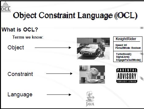
58 Class diagram - shows a set of classes, interfaces, and collaborations and their relationships. - static design view of a system. Communication Diagram - Show instance of classes,their relationship & message flow between them - Focus on structural organization, send & receive message - Known as collaboration diagram
59 Component diagram - Component,their relationship & interfaces are depicted Composite diagram - Depict internal structural of classifier such as class, component including interaction point -
60 Deployment diagram - Shows execution architecture of system, include node, h/w or s/w execution environment Interaction Overview Diagram - Variant of activity diagram which overview the control flow within system Use case diagram - Show use cases, actor & relationships
61
62 Object diagram Package diagram - Show how model element are organized into packages as well as dependencies between packages
63 Sequence diagram - Model sequential logic, ordering of message between classifiers
64 State diagram - Describe state within object Timing diagram - Depict change in state / condition
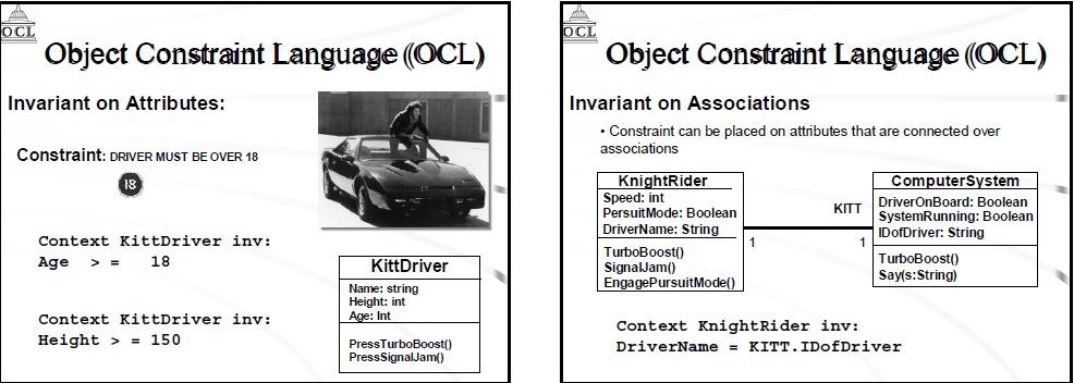
65 OBJECT CONSTRAINT LANGUAGE (OCL) OCL is a sub-language of UML that allow for capturing rules & attaching them to model elements which satisfy constraint for model to describe correct or well formed It is a declarative language for describing rules that apply to UML model The Object Constraint Language (OCL) is an expression language that describes constraints on object-oriented languages and other modeling artifacts. A constraint can be seen as a restriction on a model or a system. OCL is part of Unified Modeling Language (UML) and it plays an important role in the analysis phase of the software lifecycle.
66 Object Constraint Language (OCL), is a formal language to express side effect-free constraints. Users of the Unified Modeling Language and other languages can use OCL to specify constraints and other expressions attached to their models. OCL is the expression language for the Unified Modeling Language (UML). To understand OCL, the component parts of this statement should be examined. Thus, OCL has the characteristics of an expression language, a modeling language and a formal language. A UML diagram (e.g., a class diagram) does not provide all relevant aspects of a specification
67 It is necessary to describe additional constraints about the objects in the model Constraints specify invariant conditions that must hold for the system being modeled Constraints are often described in natural language and this always result in ambiguities Traditional formal languages allow to write unambiguous constraints, but they are difficult for the average system modeler OCL: Formal language used to express constraints, that remains easy to read and write It s a precise text lang. that provide constraints & object query expression
68
69
70
71
72 Object Constraint Language (OCL) Pure expression language: expressions do not have side effect when an OCL expression is evaluated, it returns a value its evaluation cannot alter the state of the corresponding executing system an OCL expression can be used to specify a state change (e.g., in a post condition) Not a programming language it is not possible to write program logic or flow of control in OCL cannot be used to invoke processes or activate non-query operations
73 Typed language: each expression has a type well-formed expressions must obey the type conformance rules of OCL each classifier defined in a UML model represents a distinct OCL type OCL includes a set of supplementary predefined types The evaluation of an OCL expression is instantaneous the state of objects in a model cannot change during evaluation
74 Basic Types Boolean True or False Integer Any integer value Real Any decimal value String A series of letters, numbers, symbols Casting OCL does supports casting objects from one type to another as long as they are related through a generalization relationship. oldtype.oclastype(newtype)
75 Basic Values and Types Several built-in types and operations Type Values Operations Boolean false, true or, and, xor, not, =, <>, implies Integer Real String -10, 0, 10, -1.5, 3.14, Carmen =, <>, <, >, <=, >=, +, -, *, /, mod(), div(), abs(), max(), min(), round(), floor() =, <>, concat(), size(), tolower(), toupper(), substring() 75
76 OCL Syntax Constraints on Classifiers Context Keyword: Self self.gpa>2.0 Follow associations between classifiers self.instructor.salary>0.00 If the association has multiplicity you can treat the association end as a set and check to see if the value is set by built in notempty() Self.instructor->notEmpty() If an association role name is not specified you can use the classifier name. self.course->forall(roomassignment<> No Room Comments -- make sure this student could graduate self.gpa>2.0
77
78
79 If you can t determine the context or if you want explicit context Keyword: inv context Student Inv: self.gpa>2.0 Instead of using keyword self, you can assign a name to a classifier that you can use in the expression context s : Student Inv: s.gpa>2.0 Finally you can name the expression by placing a label after the expression type but before the colon Context s : Student Inv minimumgparule: s.gpa>2.0
80 OCL Syntax Constraints on Operations Beyond basic classifiers, OCL expressions can be associated with operations to preconditions and postconditions. Keyword: pre post context Course::registerStudent(s : Student) : boolean pre : s.tuitionpaid=true when writing postconditions you can use keyword result to refer to the value return by operation. context Course::registerStudent(s : Student) : boolean pre : s.tuitionpaid=true post: result=true
81 As you can with invariants, you can name preconditions and post conditions by placing label after pre or post keyword context Course::registerStudent(s : Student) : boolean pre haspaidtuition:s.tuitionpaid=true post: sudentwasregistar:result=true You may specify the results of query operation using keyword body. Because OCL doesn t have syntax for program flow, you are limited to relatively simple expression. context Course::getHonorsStudents() : Student body : self. Student->select(GPA>3.5)
82
83
84 OCL Syntax Constraints on Attributes OCL expression can specify the initial and subsequent values for attributes of classifiers. context School::tuition: float init:
85 Conditional Advanced OCL Modeling OCL supports basic boolean expression evaluation using the ifthen-else-end if keywords For eg. context student Inv: If tuitionpaid=true then yearofgraduation=2016 else yearofgraduation=0000 endif
86 The boolean evaluation rules are: 1. True OR-ed with anything is true 2. False AND-ed with anything is false 3. False IMPLIES anything is true Context [some context here] if (... some conditions... ) then ( result = 1 post: self.iscomplete() -- for example ) endif
87
88 Advanced OCL Modeling For eg. Context student Inv: Self.GPA<1.0 IMPLIES self.yearofgraduation=0000 Variable Declaration OCL support several complex construct you can use to make your constraints more expressive and easier to write. You can break the complex expression into reusable pieces by using the let and in keyword.
89 For eg. Advanced OCL Modeling context Course inv: let salary : float= self.insructor.salary in if self.courselevel>4000 then salary>8000 else salary<8000 endif You can define variable that can be used in multiple expression on a classifier-by classifier basis using the def keyword context Course Def salary: float = self.insructor.salary
90 OCL Precedence Advanced OCL Modeling 2. Dot (.) and arrow (->) operation 3. Not and unary minus (-) 4. * And / 5. + and 6. if-then-else-endif 7. <, >, <= and >= 8. = and <> 9. AND, OR and XOR 10. IMPLIES
91 OCL Collection C -> size () C -> includes (o) C -> excludes (o) C -> count (o) C -> includesall (c2) C -> excludesall (c2) C -> isempty () C -> notempty () C -> sum () C -> exists (p) C -> forall (p) C -> isunique (e) C -> sortedby (e) C -> iterate (e)
92
93

94
95
UNIT II. Syllabus. a. An Overview of the UML: Visualizing, Specifying, Constructing, Documenting
 UNIT II Syllabus Introduction to UML (08 Hrs, 16 Marks) a. An Overview of the UML: Visualizing, Specifying, Constructing, Documenting b. Background, UML Basics c. Introducing UML 2.0 A Conceptual Model
A Conceptual Model of the UML
 CONTENT A Conceptual Model of the UML Building Blocks of the UML 1. Things [1.1] Structural Things (1.1.1) Class (1.1.2) Interface (1.1.3) Collaboration: (1.1.4) Use case (1.1.5) Components: (1.1.6) Node:
Introduction to UML Dr. Rajivkumar S. Mente
 Introduction to UML Dr. Rajivkumar S. Mente Assistant Professor, Department of Computer Science, Solapur University, Solapur rajivmente@rediffmail.com Introduction to UML UML is a language used for 1.
Metamodeling. Janos Sztipanovits ISIS, Vanderbilt University
 Metamodeling Janos ISIS, Vanderbilt University janos.sztipanovits@vanderbilt.edusztipanovits@vanderbilt edu Content Overview of Metamodeling Abstract Syntax Metamodeling Concepts Metamodeling languages
LABORATORY 1 REVISION
 UTCN Computer Science Department Software Design 2012/2013 LABORATORY 1 REVISION ================================================================== I. UML Revision This section focuses on reviewing the
INTRODUCING THE UML. Chapter 2
 chap02.fm Page 13 Friday, October 27, 2000 10:26 AM Chapter 2 INTRODUCING THE UML In this chapter Overview of the UML Three steps to understanding the UML Software architecture The software development
Allenhouse Institute of Technology (UPTU Code : 505) OOT Notes By Hammad Lari for B.Tech CSE V th Sem
 OOT Notes By Hammad Lari for B.Tech CSE V th Sem") UNIT-1 ECS-503 Object Oriented Techniques Part-1: Object-Oriented Programming Concepts What Is an Object? Objects are key to understanding object-oriented technology. Look around right now and you'll find
UNIT-1 ECS-503 Object Oriented Techniques Part-1: Object-Oriented Programming Concepts What Is an Object? Objects are key to understanding object-oriented technology. Look around right now and you'll find
Ingegneria del Software Corso di Laurea in Informatica per il Management. Introduction to UML
 Ingegneria del Software Corso di Laurea in Informatica per il Management Introduction to UML Davide Rossi Dipartimento di Informatica Università di Bologna Modeling A model is an (abstract) representation
Introduction to UML. (Unified Modeling Language)
") Introduction to UML (Unified Modeling Language) What Is the UML? UML stands for Unified Modeling Language. UML is a family of graphical notations that help in describing and designing software systems
Introduction to UML (Unified Modeling Language) What Is the UML? UML stands for Unified Modeling Language. UML is a family of graphical notations that help in describing and designing software systems
Interactions A link message
 Interactions An interaction is a behavior that is composed of a set of messages exchanged among a set of objects within a context to accomplish a purpose. A message specifies the communication between
Introduction to UML. Danang Wahyu utomo
 Introduction to UML Danang Wahyu utomo danang.wu@dsn.dinus.ac.id 085 740 955 623 Evolution of OO Development Methods History of OOAD leading to UML Why Model? Analyse the problem domain - Simplify reality
CHAPTER 5 CO:-Sketch component diagram using basic notations 5.1 Component Diagram (4M) Sample Component Diagram 5.2 Deployment Diagram (8M)
 Sample Component Diagram 5.2 Deployment Diagram (8M)") CHAPTER 5 CO:-Sketch component diagram using basic notations 5.1 Component Diagram (4M) Sample Component Diagram 5.2 Deployment Diagram (8M) Sample Deployment diagram Component diagrams are different in
CHAPTER 5 CO:-Sketch component diagram using basic notations 5.1 Component Diagram (4M) Sample Component Diagram 5.2 Deployment Diagram (8M) Sample Deployment diagram Component diagrams are different in
Vidyalankar. T.Y. Diploma : Sem. VI [IF/CM] Object Oriented Modeling and Design Prelim Question Paper Solution
![Vidyalankar. T.Y. Diploma : Sem. VI [IF/CM] Object Oriented Modeling and Design Prelim Question Paper Solution](/thumbs/86/94007497.jpg "Vidyalankar. T.Y. Diploma : Sem. VI [IF/CM] Object Oriented Modeling and Design Prelim Question Paper Solution") T.Y. Diploma : Sem. VI [IF/CM] Object Oriented Modeling and Design Prelim Question Paper Solution Q.1(a) Attempt any THREE of the following [12] Q.1(a) (i) What is modeling? Also state its four features.
T.Y. Diploma : Sem. VI [IF/CM] Object Oriented Modeling and Design Prelim Question Paper Solution Q.1(a) Attempt any THREE of the following [12] Q.1(a) (i) What is modeling? Also state its four features.
SOFTWARE DESIGN COSC 4353 / Dr. Raj Singh
 SOFTWARE DESIGN COSC 4353 / 6353 Dr. Raj Singh UML - History 2 The Unified Modeling Language (UML) is a general purpose modeling language designed to provide a standard way to visualize the design of a
Basic Structural Modeling. Copyright Joey Paquet,
 Basic Structural Modeling Copyright Joey Paquet, 2000 1 Part I Classes Copyright Joey Paquet, 2000 2 Classes Description of a set of objects sharing the same attributes, operations and semantics Abstraction
Unified Modeling Language
 Unified Modeling Language Modeling Applications using Language Mappings Programmer s Reference Manual How to use this Reference Card: The consists of a set of fundamental modeling elements which appear
UNIT-IV BASIC BEHAVIORAL MODELING-I
 UNIT-IV BASIC BEHAVIORAL MODELING-I CONTENTS 1. Interactions Terms and Concepts Modeling Techniques 2. Interaction Diagrams Terms and Concepts Modeling Techniques Interactions: Terms and Concepts: An interaction
UNIT 5 - UML STATE DIAGRAMS AND MODELING
 UNIT 5 - UML STATE DIAGRAMS AND MODELING UML state diagrams and modeling - Operation contracts- Mapping design to code UML deployment and component diagrams UML state diagrams: State diagrams are used
COSC 3351 Software Design. An Introduction to UML (I)
") COSC 3351 Software Design An Introduction to UML (I) This lecture contains material from: http://wps.prenhall.com/esm_pfleeger_softengtp_2 http://sunset.usc.edu/classes/cs577a_2000/lectures/05/ec-05.ppt
COSC 3351 Software Design An Introduction to UML (I) This lecture contains material from: http://wps.prenhall.com/esm_pfleeger_softengtp_2 http://sunset.usc.edu/classes/cs577a_2000/lectures/05/ec-05.ppt
Introduction to Software Engineering. 5. Modeling Objects and Classes
 Introduction to Software Engineering 5. Modeling Objects and Classes Roadmap > UML Overview > Classes, attributes and operations > UML Lines and Arrows > Parameterized Classes, Interfaces and Utilities
Lab Manual. Object Oriented Analysis And Design. TE(Computer) VI semester
 VI semester") Lab Manual Object Oriented Analysis And Design TE(Computer) VI semester Index Sr. No. Title of Programming Assignment Page No. 1 2 3 4 5 6 7 8 9 10 Study of Use Case Diagram Study of Activity Diagram Study
Lab Manual Object Oriented Analysis And Design TE(Computer) VI semester Index Sr. No. Title of Programming Assignment Page No. 1 2 3 4 5 6 7 8 9 10 Study of Use Case Diagram Study of Activity Diagram Study
Software Design Methodologies and Testing. (Subject Code: ) (Class: BE Computer Engineering) 2012 Pattern
 (Class: BE Computer Engineering) 2012 Pattern") Software Design Methodologies and Testing (Subject Code: 410449) (Class: BE Computer Engineering) 2012 Pattern Objectives and outcomes Course Objectives To understand and apply different design methods
Software Design Methodologies and Testing (Subject Code: 410449) (Class: BE Computer Engineering) 2012 Pattern Objectives and outcomes Course Objectives To understand and apply different design methods
CHAPTER 1. Topic: UML Overview. CHAPTER 1: Topic 1. Topic: UML Overview
 CHAPTER 1 Topic: UML Overview After studying this Chapter, students should be able to: Describe the goals of UML. Analyze the History of UML. Evaluate the use of UML in an area of interest. CHAPTER 1:
Modellistica Medica. Maria Grazia Pia, INFN Genova. Scuola di Specializzazione in Fisica Sanitaria Genova Anno Accademico
 Modellistica Medica Maria Grazia Pia INFN Genova Scuola di Specializzazione in Fisica Sanitaria Genova Anno Accademico 2002-2003 Lezione 6 UML Introduction Structural diagrams Basics What is? Please explain
MAHARASHTRA STATE BOARD OF TECHNICAL EDUCATION (Autonomous) (ISO/IEC Certified)
 (ISO/IEC Certified)") Important Instructions to examiners: 1) The answers should be examined by key words and not as word-to-word as given in the model answer scheme. 2) The model answer and the answer written by candidate
Important Instructions to examiners: 1) The answers should be examined by key words and not as word-to-word as given in the model answer scheme. 2) The model answer and the answer written by candidate
OO Analysis and Design with UML 2 and UP
 OO Analysis and Design with UML 2 and UP Dr. Jim Arlow, Zuhlke Engineering Limited Clear View Training 2008 v2.5 1 UML principles Clear View Training 2008 v2.5 2 1.2 What is UML? Unified Modelling Language
Chapter 10. Object-Oriented Analysis and Modeling Using the UML. McGraw-Hill/Irwin
 Chapter 10 Object-Oriented Analysis and Modeling Using the UML McGraw-Hill/Irwin Copyright 2007 by The McGraw-Hill Companies, Inc. All rights reserved. Objectives 10-2 Define object modeling and explain
Software Engineering from a
 Software Engineering from a modeling perspective Robert B. France Dept. of Computer Science Colorado State University USA france@cs.colostate.edu Softwaredevelopment problems Little or no prior planning
UML Fundamental. OutLine. NetFusion Tech. Co., Ltd. Jack Lee. Use-case diagram Class diagram Sequence diagram
 UML Fundamental NetFusion Tech. Co., Ltd. Jack Lee 2008/4/7 1 Use-case diagram Class diagram Sequence diagram OutLine Communication diagram State machine Activity diagram 2 1 What is UML? Unified Modeling
Composite Structures
 Composite Structures Marie-Agnès Peraldi-Frati UNSA/I3S/INRIA map@unice.fr UML 2 Composition Model Purpose: improve the black diamond composition Supports connections between parts at the same level of
UML Tutorial. Unified Modeling Language UML Tutorial
 UML Tutorial Unified Modeling Language UML Tutorial A Unified Modeling Language is a language for specifying, constructing, visualizing and documenting the software system and its components. UML is a
user.book Page 45 Friday, April 8, :05 AM Part 2 BASIC STRUCTURAL MODELING
 user.book Page 45 Friday, April 8, 2005 10:05 AM Part 2 BASIC STRUCTURAL MODELING user.book Page 46 Friday, April 8, 2005 10:05 AM user.book Page 47 Friday, April 8, 2005 10:05 AM Chapter 4 CLASSES In
UNIT-4 Behavioral Diagrams
 UNIT-4 Behavioral Diagrams P. P. Mahale Behavioral Diagrams Use Case Diagram high-level behaviors of the system, user goals, external entities: actors Sequence Diagram focus on time ordering of messages
Software Service Engineering
 Software Service Engineering Lecture 4: Unified Modeling Language Doctor Guangyu Gao Some contents and notes selected from Fowler, M. UML Distilled, 3rd edition. Addison-Wesley Unified Modeling Language
Chapter No. 2 Class modeling CO:-Sketch Class,object models using fundamental relationships Contents 2.1 Object and Class Concepts (12M) Objects,
 Objects,") Chapter No. 2 Class modeling CO:-Sketch Class,object models using fundamental relationships Contents 2.1 Object and Class Concepts (12M) Objects, Classes, Class Diagrams Values and Attributes Operations
Chapter No. 2 Class modeling CO:-Sketch Class,object models using fundamental relationships Contents 2.1 Object and Class Concepts (12M) Objects, Classes, Class Diagrams Values and Attributes Operations
Advanced Software Engineering
 Dev Bhoomi Institute Of Technology LABORATORY MANUAL PRACTICAL INSTRUCTION SHEET EXPERIMENT NO. ISSUE NO. : ISSUE DATE: REV. NO. : REV. DATE : PAGE: 1 LABORATORY Name & Code: Advanced Software Engineering
Experiment no 4 Study of Class Diagram in Rational Rose
 Experiment no 4 Study of Class Diagram in Rational Rose Objective-: To studyclass Diagram in Rational Rose. References-: www.developer.com The Unified Modeling Language User Guide by Grady Booch Mastering
Unit-II Programming and Problem Solving (BE1/4 CSE-2)
") Unit-II Programming and Problem Solving (BE1/4 CSE-2) Problem Solving: Algorithm: It is a part of the plan for the computer program. An algorithm is an effective procedure for solving a problem in a finite
Unit-II Programming and Problem Solving (BE1/4 CSE-2) Problem Solving: Algorithm: It is a part of the plan for the computer program. An algorithm is an effective procedure for solving a problem in a finite
Object-Oriented Systems Analysis and Design Using UML
 10 Object-Oriented Systems Analysis and Design Using UML Systems Analysis and Design, 8e Kendall & Kendall Copyright 2011 Pearson Education, Inc. Publishing as Prentice Hall Learning Objectives Understand
Topics. Overview- The UML Functional Model. Structural Model. Behavioral Models. Use Case Diagram (essential and system)
") Topics Overview- The UML Functional Model Use Case Diagram (essential and system) Structural Model Class/object, Component and Deployment Diagram Behavioral Models Activity, State chart, sequence /collaboration
Topics Overview- The UML Functional Model Use Case Diagram (essential and system) Structural Model Class/object, Component and Deployment Diagram Behavioral Models Activity, State chart, sequence /collaboration
Index. business modeling syntax 181 business process modeling 57 business rule 40
 OCL.book Page 203 Tuesday, July 22, 2003 9:48 PM Index Symbols OclAny, of 167 = OclAny, of 167 @pre 34, 86, 155 ^ 34, 156 ^^ 157 A abstract syntax 93 accumulator 153 action in statechart 56 activity
Rubby Casallas Grupo de Construcción de Software Uniandes
 UML OCL 2.0 Rubby Casallas Grupo de Construcción de Software Uniandes Why OCL? A UML diagram, such as a class diagram, is typically not refined enough to provide all the relevant aspects of a specification.
UML REFERENCE SHEETS. 2013, 2014 Michael Marking; all rights reserved, including moral rights. Web site:
 UML Reference Sheets 2013, 2014 Michael Marking; all rights reserved, including moral rights. Web site: http://www.tatanka.com/ Revision Information This document was last revised 2014.03.02. The current
Unified Modeling Language (UML)
") Unified Modeling Language (UML) Troy Mockenhaupt Chi-Hang ( Alex) Lin Pejman ( PJ ) Yedidsion Overview Definition History Behavior Diagrams Interaction Diagrams Structural Diagrams Tools Effect on Software
Unified Modeling Language (UML) Troy Mockenhaupt Chi-Hang ( Alex) Lin Pejman ( PJ ) Yedidsion Overview Definition History Behavior Diagrams Interaction Diagrams Structural Diagrams Tools Effect on Software
OMG Modeling Glossary B
 OMG Modeling Glossary B This glossary defines the terms that are used to describe the Unified Modeling Language (UML) and the Meta Object Facility (MOF). In addition to UML and MOF specific terminology,
UML 2.0 UML 2.0. Scott Uk-Jin Lee. Division of Computer Science, College of Computing Hanyang University ERICA Campus
 UML 2.0 Division of Computer Science, College of Computing Hanyang University ERICA Campus Introduction to UML 2.0 UML Unified Modeling Language Visual language for specifying, constructing and documenting
Design of Embedded Systems
 Design of Embedded Systems José Costa Software for Embedded Systems Departamento de Engenharia Informática (DEI) Instituto Superior Técnico 2015-01-02 José Costa (DEI/IST) Design of Embedded Systems 1
Architectural Models and Styles Component-Based Software Engineering ECE493-Topic 5 Winter 2007 Lecture 12 The Object Constraint Language (Part A)
") Component-Based Software Engineering ECE493-Topic 5 Winter 2007 Lecture 12 The Object Constraint Language (Part A) Ladan Tahvildari Assistant Professor Dept. of Elect. & Comp. Eng. University of Waterloo
Component-Based Software Engineering ECE493-Topic 5 Winter 2007 Lecture 12 The Object Constraint Language (Part A) Ladan Tahvildari Assistant Professor Dept. of Elect. & Comp. Eng. University of Waterloo
Enterprise Architect. User Guide Series. UML Models. Author: Sparx Systems. Date: 30/06/2017. Version: 1.0 CREATED WITH
 Enterprise Architect User Guide Series UML Models Author: Sparx Systems Date: 30/06/2017 Version: 1.0 CREATED WITH Table of Contents UML Models UML Diagrams UML Structural Models Class Diagram Composite
MAHARASHTRA STATE BOARD OF TECHNICAL EDUCATION (Autonomous) (ISO/IEC Certified) MODEL ANSWER
 (ISO/IEC Certified) MODEL ANSWER") Important Instructions to examiners: 1) The answers should be examined by key words and not as word-to-word as given in the model answer scheme. 2) The model answer and the answer written by candidate
Important Instructions to examiners: 1) The answers should be examined by key words and not as word-to-word as given in the model answer scheme. 2) The model answer and the answer written by candidate
A - 1. CS 494 Object-Oriented Analysis & Design. UML Class Models. Overview. Class Model Perspectives (cont d) Developing Class Models
 Developing Class Models") CS 494 Object-Oriented Analysis & Design UML Class Models Overview How class models are used? Perspectives Classes: attributes and operations Associations Multiplicity Generalization and Inheritance Aggregation
CS 494 Object-Oriented Analysis & Design UML Class Models Overview How class models are used? Perspectives Classes: attributes and operations Associations Multiplicity Generalization and Inheritance Aggregation
UML- a Brief Look UML and the Process
 UML- a Brief Look UML grew out of great variety of ways Design and develop object-oriented models and designs By mid 1990s Number of credible approaches reduced to three Work further developed and refined
IS 0020 Program Design and Software Tools
 1 IS 0020 Program Design and Software Tools Unified Modeling Language Lecture 13 April 13, 2005 What is UML? 2 The Unified Modelling Language is a standard notation to model [object oriented] systems.
What is OCL? OCL/Context
 What is? Software Engineering Lecture 5: Prof. Dr. Peter Thiemann Universität Freiburg SS 20 = object constraint language standard query language of UML 2 specify expressions and constraints in object-oriented
Introducing the UML Eng. Mohammed T. Abo Alroos
 Introducing the UML Eng. Mohammed T. Abo Alroos Islamic University of Gaza Introduction to the UML: The UML stands for Unified Modeling Language. It was released in 1997 as a method to diagram software
 Object Constraint https://www.lri.fr/~linaye/gl.html lina.ye@centralesupelec.fr Sequence 3, 2017-2018 1/45 Plan 1 2 3 4 2/45 Motivation Why OCL Cannot represent all the relevant aspects of a specification
UNIT-II I. BASIC STRUCTURAL MODELING
 UNIT-II I. BASIC STRUCTURAL MODELING Contents: 1. Classes 2. Relationships 3. Common Mechanisms 4. Diagrams 1. Classes: Terms and Concepts: A class is a description of a set of objects that share the same
Object Oriented Design. Program Design. Analysis Phase. Part 2. Analysis Design Implementation. Functional Specification
 Object Oriented Design Part 2 Analysis Design Implementation Program Design Analysis Phase Functional Specification Completely defines tasks to be solved Free from internal contradictions Readable both
Modeling with UML. (1) Use Case Diagram. (2) Class Diagram. (3) Interaction Diagram. (4) State Diagram
 Use Case Diagram. (2) Class Diagram. (3) Interaction Diagram. (4) State Diagram") Modeling with UML A language or notation intended for analyzing, describing and documenting all aspects of the object-oriented software system. UML uses graphical notations to express the design of software
Modeling with UML A language or notation intended for analyzing, describing and documenting all aspects of the object-oriented software system. UML uses graphical notations to express the design of software
3. UML Class Diagrams Page 1 of 15
 3. UML Class Diagrams Page 1 of 15 The UML Class Diagram: Part 1 In the last article, we saw what use cases were, and how to identify and create use cases. Taking the series ahead, in this article, we
Chapter 1: Principles of Programming and Software Engineering
 Chapter 1: Principles of Programming and Software Engineering Data Abstraction & Problem Solving with C++ Fifth Edition by Frank M. Carrano Software Engineering and Object-Oriented Design Coding without
Chapter 5: Structural Modeling
 Chapter 5: Structural Modeling Objectives Understand the rules and style guidelines for creating CRC cards, class diagrams, and object diagrams. Understand the processes used to create CRC cards, class
Weiss Chapter 1 terminology (parenthesized numbers are page numbers)
") Weiss Chapter 1 terminology (parenthesized numbers are page numbers) assignment operators In Java, used to alter the value of a variable. These operators include =, +=, -=, *=, and /=. (9) autoincrement
Weiss Chapter 1 terminology (parenthesized numbers are page numbers) assignment operators In Java, used to alter the value of a variable. These operators include =, +=, -=, *=, and /=. (9) autoincrement
Exercise Unit 2: Modeling Paradigms - RT-UML. UML: The Unified Modeling Language. Statecharts. RT-UML in AnyLogic
 Exercise Unit 2: Modeling Paradigms - RT-UML UML: The Unified Modeling Language Statecharts RT-UML in AnyLogic Simulation and Modeling I Modeling with RT-UML 1 RT-UML: UML Unified Modeling Language a mix
Introduction to UML CHAPTER 1. Visualizing. Specifying LEARNING OBJECTIVES
 CHAPTER 1 Introduction to UML UML is an acronym for Unified Modeling Language. As its name indicates, it is a graphical language, used to create visual models of software intensive systems. The UML is
Course "Softwaretechnik" Book Chapter 2 Modeling with UML
 Course "Softwaretechnik" Book Chapter 2 Modeling with UML Lutz Prechelt, Bernd Bruegge, Allen H. Dutoit Freie Universität Berlin, Institut für Informatik http://www.inf.fu-berlin.de/inst/ag-se/ Modeling,
UNIT V *********************************************************************************************
 Syllabus: 1 UNIT V 5. Package Diagram, Component Diagram, Deployment Diagram (08 Hrs, 16 Marks) Package Diagram: a. Terms and Concepts Names, Owned Elements, Visibility, Importing and Exporting b. Common
Software Engineering
 Software Engineering Lecture 15: OCL Peter Thiemann University of Freiburg, Germany 01.07.2013 Peter Thiemann (Univ. Freiburg) Software Engineering 01.07.2013 1 / 28 What is OCL? OCL = Object Constraint
OBJECT ORIENTED SIMULATION LANGUAGE. OOSimL Reference Manual - Part 1
 OBJECT ORIENTED SIMULATION LANGUAGE OOSimL Reference Manual - Part 1 Technical Report TR-CSIS-OOPsimL-1 José M. Garrido Department of Computer Science Updated November 2014 College of Computing and Software
Lesson 11. W.C.Udwela Department of Mathematics & Computer Science
 Lesson 11 INTRODUCING UML W.C.Udwela Department of Mathematics & Computer Science Why we model? Central part of all the activities We build model to Communicate Visualize and control Better understand
SE 1: Software Requirements Specification and Analysis
 SE 1: Software Requirements Specification and Analysis Lecture 9: UML Class (Concept), Object, Communication Diagrams Nancy Day, Davor Svetinović http://www.student.cs.uwaterloo.ca/ cs445/winter2006 uw.cs.cs445
Object-Oriented and Classical Software Engineering
 Slide 16.1 Object-Oriented and Classical Software Engineering Seventh Edition, WCB/McGraw-Hill, 2007 Stephen R. Schach srs@vuse.vanderbilt.edu CHAPTER 16 Slide 16.2 MORE ON UML 1 Chapter Overview Slide
MAHARASHTRA STATE BOARD OF TECHNICAL EDUCATION (Autonomous) (ISO/IEC Certified)
 (ISO/IEC Certified)") Subject Code: 17630 Model Answer Page No: 1 /32 Important Instructions to examiners: 1) The answers should be examined by keywords and not as word-to-word as given in the model answer scheme. 2) The model
Subject Code: 17630 Model Answer Page No: 1 /32 Important Instructions to examiners: 1) The answers should be examined by keywords and not as word-to-word as given in the model answer scheme. 2) The model
Pattern for Structuring UML-Compatible Software Project Repositories
 Pattern for Structuring UML-Compatible Software Project Repositories Pavel Hruby Navision Software a/s Frydenlunds Allé 6 2950 Vedbaek, Denmark E-mail: ph@navision.com Web site: www.navision.com/services/methodology/default.asp
UML Unified Modeling Language
 UML Unified Modeling Language a standard language to analyze, design and document software intensive solutions Modeling with UML Building blocks When you model something, you create a simplification of
Agenda. More on the Unified Modeling Language. UML diagram types. Packages
 Agenda More on the Unified Modeling Language Perdita Stevens, University of Edinburgh July 2010 And the rest... deployment diagrams, component diagrams, object diagrams, timing diagrams, etc. OCL and alternatives
CHAPTER 5 ARCHITECTURAL DESIGN SE211 SOFTWARE DESIGN
 CHAPTER 5 ARCHITECTURAL DESIGN SE211 SOFTWARE DESIGN Assist. Prof. Dr. Volkan TUNALI Faculty of Engineering and Natural Sciences / Maltepe University OVERVIEW 2 SECTION 1 Architectural Design SECTION 2
Unified Modeling Language 2
 Unified Modeling Language 2 Profiles 166 Usage scenarios Metamodel customization for adapting terminology to a specific platform or domain adding (visual) notation adding and specializing semantics adding
Introduction to Software Engineering. ECSE-321 Unit 9 Architectural Design Approaches
 Introduction to Software Engineering ECSE-321 Unit 9 Architectural Design Approaches Requirement Elicitation Analysis (Software Product Design) Architectural Design Detailed Design Architectural Design
Formal Methods in Software Engineering 1
 Building Models with OCL Introduction Completing UML Diagrams Modeling Tips and Hints Summary Formal Methods in Software Engineering 1 What Is a Model? Simply put, a model is a high level system description.
OCL Support in MOF Repositories
 OCL Support in MOF Repositories Joachim Hoessler, Michael Soden Department of Computer Science Technical University Berlin hoessler@cs.tu-berlin.de, soden@cs.tu-berlin.de Abstract From metamodels that
Unit II. Advanced Structural Modeling
 Unit II Advanced Structural Modeling A relationship is a connection among things. In object-oriented modeling, the four most important relationships are dependencies, generalizations, associations, and
SOFTWARE ENGINEERING UML FUNDAMENTALS. Saulius Ragaišis.
 SOFTWARE ENGINEERING UML FUNDAMENTALS Saulius Ragaišis saulius.ragaisis@mif.vu.lt Information source Slides are prepared on the basis of Bernd Oestereich, Developing Software with UML: Object- Oriented
12 Tutorial on UML. TIMe TIMe Electronic Textbook
 TIMe TIMe Electronic Textbook 12 Tutorial on UML Introduction......................................................2.................................................3 Diagrams in UML..................................................3
Architecture and the UML
 Architecture and the UML Models, Views, and A model is a complete description of a system from a particular perspective Use Case Use Case Sequence Use Case Use Case Use Case State State Class State State
What is a Class Diagram? A diagram that shows a set of classes, interfaces, and collaborations and their relationships
 Class Diagram What is a Class Diagram? A diagram that shows a set of classes, interfaces, and collaborations and their relationships Why do we need Class Diagram? Focus on the conceptual and specification
What is a Class Diagram? Class Diagram. Why do we need Class Diagram? Class - Notation. Class - Semantic 04/11/51
 What is a Class Diagram? Class Diagram A diagram that shows a set of classes, interfaces, and collaborations and their relationships Why do we need Class Diagram? Focus on the conceptual and specification
INTRODUCTION TO UNIFIED MODELING MODEL (UML) & DFD. Slides by: Shree Jaswal
 & DFD. Slides by: Shree Jaswal") INTRODUCTION TO UNIFIED MODELING MODEL (UML) & DFD Slides by: Shree Jaswal What is UML? 2 It is a standard graphical language for modeling object oriented software. It was developed in mid 90 s by collaborative
INTRODUCTION TO UNIFIED MODELING MODEL (UML) & DFD Slides by: Shree Jaswal What is UML? 2 It is a standard graphical language for modeling object oriented software. It was developed in mid 90 s by collaborative
Research Paper on Implementation of OCL Constraints in JAVA
 ISSN No. 0976-5697 Volume 8, No. 5, May June 2017 International Journal of Advanced Research in Computer Science RESEARCH PAPER Available Online at www.ijarcs.info Research Paper on Implementation of OCL
Practical UML - A Hands-On Introduction for Developers
 Practical UML - A Hands-On Introduction for Developers By: Randy Miller (http://gp.codegear.com/authors/edit/661.aspx) Abstract: This tutorial provides a quick introduction to the Unified Modeling Language
The PCAT Programming Language Reference Manual
 The PCAT Programming Language Reference Manual Andrew Tolmach and Jingke Li Dept. of Computer Science Portland State University September 27, 1995 (revised October 15, 2002) 1 Introduction The PCAT language
SPARK-PL: Introduction
 Alexey Solovyev Abstract All basic elements of SPARK-PL are introduced. Table of Contents 1. Introduction to SPARK-PL... 1 2. Alphabet of SPARK-PL... 3 3. Types and variables... 3 4. SPARK-PL basic commands...
OO Techniques & UML Class Diagrams
 OO Techniques & UML Class Diagrams SE3A04 Tutorial Jason Jaskolka Department of Computing and Software Faculty of Engineering McMaster University Hamilton, Ontario, Canada jaskolj@mcmaster.ca October 17,
IDERA ER/Studio Software Architect Evaluation Guide. Version 16.5/2016+ Published February 2017
 IDERA ER/Studio Software Architect Evaluation Guide Version 16.5/2016+ Published February 2017 2017 IDERA, Inc. All rights reserved. IDERA and the IDERA logo are trademarks or registered trademarks of
Darshan Institute of Engineering & Technology for Diploma Studies
 REQUIREMENTS GATHERING AND ANALYSIS The analyst starts requirement gathering activity by collecting all information that could be useful to develop system. In practice it is very difficult to gather all
Introduction to Software Engineering. 5. Modeling Objects and Classes
 Introduction to Software Engineering 5. Modeling Objects and Classes Roadmap > UML Overview > Classes, attributes and operations > UML Lines and Arrows > Parameterized Classes, Interfaces and Utilities
Introduction to UML What is UML? Motivations for UML Types of UML diagrams UML syntax Descriptions of the various diagram types Rational Rose (IBM.. M
 Introduction to UML Part I 1 What is UML? Unified Modeling Language, a standard language for designing and documenting a system in an object- oriented manner. It s a language by which technical architects
CS211 Lecture: Modeling Dynamic Behaviors of Systems; Interaction Diagrams and Statecharts Diagrams in UML
 CS211 Lecture: Modeling Dynamic Behaviors of Systems; Interaction Diagrams and Statecharts Diagrams in UML Objectives: 1. To introduce the notion of dynamic analysis 2. To show how to create and read Sequence
UML 2.0 Profile for ArchWare ADL: Coping with UML 2.0
 ArchWare Architecting Evolvable Software www.architecture-ware.org European RTD Project IST-2001-32360 UML 2.0 Profile for ArchWare ADL: Coping with UML 2.0 (Project Deliverable D1.8) Author: Editor: Flavio
History of object-oriented approaches
 Prof. Dr. Nizamettin AYDIN naydin@yildiz.edu.tr http://www.yildiz.edu.tr/~naydin Object-Oriented Oriented Systems Analysis and Design with the UML Objectives: Understand the basic characteristics of object-oriented