SERDESUB 913ROS DS90UB913Q Serializer and DS90UB914Q Deserializer Evaluation Kit User s Manual
|
|
|
- Norah Hunter
- 5 years ago
- Views:
Transcription
1 SERDESUB 913ROS DS90UB913Q Serializer and DS90UB914Q Deserializer Evaluation Kit User s Manual Rev Texas Instruments 11/19/2012
2 Contents SERDESUB 913ROS... 1 DS90UB913Q Serializer and DS90UB914Q Deserializer Evaluation Kit... 1 User s Manual... 1 Introduction:... 3 DS90UB913Q/914Q SerDes Typical Application... 4 How to set up the Demo Evaluation Kit:... 5 Bi Directional Control Bus And I2C Modes:... 5 Demo Board Power Connections:... 6 DS9UB913Q Serializer Board Description:... 6 The 2x15 pin IDC connector JP1 accepts 10/12 bits of 1.8V or 3.3V data, HS, VS and PCLK. VDDIO must be set externally for 1.8V or 3.3V LVCMOS inputs Configuring the Mode Pin on the Serializer Board... 6 Serializer LVCMOS Pinout by Connector... 6 DS9UB914Q Deserializer Board Description: Dip Switch S2 Configuration on the Deserializer Board Dip Switch S1 Configuration on the Deserializer Board Deserializer LVCMOS Pinout by Connector Typical Connection and Test Equipment I 2 C Communication over Bi directional Control Channel in Camera Mode Camera Mode: I 2 C Communication over Bi directional Control Channel in Camera Mode Troubleshooting Demo Setup Cable References Appendix DS90UB913Q EVK Schematic DS90UB914Q EVK Schematic DS90UB913Q PCB Layout DS90UB914Q EVK Layout Texas Instruments 11/19/2012
3 Introduction: National Semiconductor s Automotive SERDES DS90UB913/914Q FPD Link III evaluation kit contains one (1) DS90UB913Q Serializer board and one (1) DS90UB914Q Deserializer board. The boards are mounted with the Rosenberger connectors for connectivity using the Leoni Dacar cables (not sent along with the kits). The boards also have the option of being populated with single ended coaxial cables. The DS90UB913Q/914Q chipset supports a variety of automotive mega pixel camera systems over a two (2) wire serial stream. The single differential pair (FPD Link III) is well suited for direct connections between an imager and Host Controller/Electronic Control Unit (ECU)/FPGA. The bidirectional control channel of the DS90UB913Q/914Q provides seamless communication between the ECU/FPGA and the display module. This kit will demonstrate the functionality and operation of the DS90UB913Q and DS90UB914Q chipset. The chipset enables transmission of a high speed video data along with a low latency bi directional control bus over a single twisted pair cable. The integrated control channel transfers data bidirectionally over the same serial video link. The transport delivers 10/12 bits of parallel data, two SYNC bits and PCLK together with a bidirectional control channel that supports an I2C bus. Additionally, there are four unidirectional general purpose (GPI and GPO) signal lines for sending control data. This interface allows transparent full duplex communication over a single high speed differential pair, carrying asymmetrical bi directional control information without the dependency of video blanking intervals. The Serializer and Deserializer chipset is designed to transmit data at PCLK clocks speeds ranging from 10 to 100 MHz and I2C bus rates up to 400 kbps at up to 10 meters cable length over 40 to +105 Deg C. The user needs to supply only a single 5V supply to the Deserializer boards as these kits have power transfer over coax/ power transfer over differential pair capabilities. The demo boards can be used for EMI testing. System Requirements: In order to demonstrate, the following are required: 1) Mega pixel imager modules such as the Omnivision OV10630 or Aptina MT9M023. 2) Microcontroller (MCU) or FPGA with I2C interface bus (I2C master) a. slave clock stretching must be supported by the I2C master controller/mcu. 3) External peripheral device that supports I2C (slave mode) 4) 5V power supply. Contents of the Demo Evaluation Kit: 1) One Serializer board with the DS90UB913Q 2) One Deserializer board with the DS90UB914Q 3) Evaluation Kit Documentation (this manual) 3 Texas Instruments 11/19/2012
4 4) DS90UB913Q/914Q Datasheet DS90UB913Q/914Q SerDes Typical Application Figure 1. Typical Application of DS90UB913/914Q Chipset The diagram above illustrates a typical application of DS90UB913Q/914Q chipset. The ECU/FPGA can program device registers on the DS90UB913Q, DS90UB914Q, and remote peripheral device, such as a display module. Video Control Module / FPGA Imager / Video Processo (Video Data + Ctrl) (I2C_CTRL) DS90UB903Q DS90UB913Q Serializer FPD-LINK III DS90UB904Q DS90UB914Q Deserializer (I2C_CTRL) (Video Data + Ctrl) Timing MCU/FPGA/ / Display Controller Figure 2. Typical DS90UB913/914Q Imager System Diagram Refer to the proper datasheet information on Chipsets (Serializer/Deserializer) provided on each board for more detailed information. 4 Texas Instruments 11/19/2012
5 How to set up the Demo Evaluation Kit: The DS90UB913Q/914Q evaluation boards consist of two sections. The first part of the board provides the point to point interface for transmitting parallel video data. The second part of the board allows bidirectional control communication of an I2C bus control of using a MCU/FPGA to programming a remote peripheral device via the Serializer. The PCB routing for the Serializer input pins (DIN) accept incoming parallel video data at 1.8V/3.3V LVCMOS signals from J1 IDC connector. The FPD Link III interface can use a single twisted pair cable or a single coax cable. The output pins (ROUT) are accessed through a JP1 IDC connector. Please follow these steps to set up the evaluation kit for bench testing and performance measurements: 1) Connect the DS90UB913/914Q demo boards using a Leoni/Dacar cable or a coaxial cable( not provided) 2) Jumpers and switches have been configured at the factory; they should not require any changes for immediate operation of the chipset. See text on Configuration settings and datasheet for more details. The jumpers and connectors are configured in external oscillator mode with the VDDIOs toggling at 3.3V. 3) From the imager, connect a flat cable (not supplied) to the Serializer board and connect another flat cable (not supplied) from the Deserializer board to the ECU/FPGA module. Note: For 50 ohm signal sources, provide 1.8V/3.3V LVCMOS input signal levels into DIN[12:0], HS, VS and PCLK 4) Connect the Deserializer I2C ports to the I2C of the MCU/FPGA (I2C master). Connect the Serializer I2C ports to the I2C bus of the peripheral slave device. 5) Power for the Serializer and Deserializer boards must be supplied externally through JP5 on the Deserializer board and JP4 on the Serializer board. Bi Directional Control Bus And I2C Modes: In order to communicate and synchronize with remote devices on the I2C bus through the bi directional control channel, slave clock stretching must be supported by the I2C master controller/ecu. The chipset utilizes bus clock stretching (holding the SCL line low) during data transmission; where the I2C slave pulls the SCL line low prior to the 9th clock of every I2C data transfer (before the ACK signal). The bidirectional control bus supports an I2C compatible interface that allows programming of the DS90UB913Q, DS90UB914Q, or an external remote device (such as an imager). Register programming transactions to/from the DS90UB913Q/914Q chipset are employed through the clock (SCL) and data (SDA) lines. These two signals have open drain I/Os and must be pulled up to VDDIO by external resistors. The boards have an option to use the on board 10KΩ pull up resistors tied to VDDIO or connected through external pull ups at the target Host. The appropriate pull up resistor values will depend upon the total bus capacitance and operating speed. The DS90UB913Q/914Q I2C bus data rate supports up to 400 kbps according to I2C specification. 5 Texas Instruments 11/19/2012
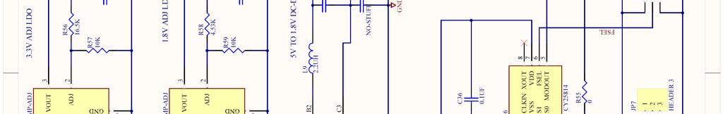
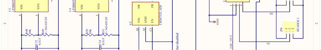
6 Demo Board Power Connections: Power should be only applied to the DS90UB914Q Deserializer boards. Power is transferred over the link using either the Differential pair or the coaxial link. DS9UB913Q Serializer Board Description: The 2x15 pin IDC connector JP1 accepts 10/12 bits of 1.8V or 3.3V data, HS, VS and PCLK. VDDIO must be set externally for 1.8V or 3.3V LVCMOS inputs. The Serializer board can be powered from the Deserializer board. For the Serializer to be operational, the S1 PDB switch on 1 must be set HIGH. S1 RES0 must be set LOW. The boards can be connected to the Deserializer boards using either Rosenberger connectors or co axial connectors as shown in Figure 3Figure 3. DS90UB913Q Boards with HSD Connector and Figure 4. Configuring the Mode Pin on the Serializer Board To configure the device in the external oscillator mode, PCLK mode or the AON clock mode, switch S8 has to be configured as shown in Table. 1. Mode Configuration PCLK from imager Switch S8 Settings External Oscillator Mode Table 1. Mode switch configuration on the Serializer Board Serializer LVCMOS Pinout by Connector The following three tables illustrate how the Deserializer connections are mapped to the IDC connector J1 on the Serializer board. 6 Texas Instruments 11/19/2012
7 JP1 LVCMOS I/O pin no. name name pin no. 1 GND DIN0 2 3 GND DIN1 4 5 GND DIN2 6 7 GND DIN3 8 9 GND DIN GND DIN GND DIN GND DIN GND DIN GND DIN GND DIN GND DIN GND HS GND VS GND PCLK 30 7 Texas Instruments 11/19/2012

8 Switch 1 PDB S1 JP1 : D0:D11, HS, VS, PCLK Switch 2 RES0 (Tied Low) S2 Switch 3 External Oscillator mode JP4 Power Figure 3. DS90UB913Q Boards with HSD Connector Switch 5 Direct PCLK Mode 8 Texas Instruments 11/19/2012

9 S1 JP1 : D0:D11, HS, VS, PCLK Switch 1 PDB Switch 2 RES0 S2 JP4 Power Switch 3 External Oscillator mode Switch 5 Direct PCLK Mode Figure 4. DS90UB913Q Board with Coax connector 9 Texas Instruments 11/19/2012
10 DS9UB914Q Deserializer Board Description: The Deserializer board can be powered using header JP5. For the Deserializer to be operational, follow the dip switch configuration S1 shown in Table 2 and Table 3. The 2x15 pin IDC Connector JP1 provides access to the 1.8V or 3.3V LVCMOS data, HS, VS and PCLK outputs. The Deserializer board is by default configured to operate in the 100MHz mode with 1.8V I/O. The default device address of the DS90UB914Q on the Board is C0. Dip Switch S2 Configuration on the Deserializer Board To configure the DS90UB914Q device on the Deserializer board, please follow Table.2. Mode Configuration 12 bit Low Frequency Mode Switch S6 Settings 12 bit High Frequency Mode 10 bit Mode Table 2. Mode Switch Configuration on the Deserializer Board Dip Switch S1 Configuration on the Deserializer Board To configure the DS90UB914Q device on the Deserializer board, please follow Table.2. Mode Configuration Switch S6 Settings Normal Mode configuration BIST Mode configuration Table 3. Mode Switch Configuration on the Deserializer Board 10 Texas Instruments 11/19/2012
11 Deserializer LVCMOS Pinout by Connector The following table illustrates how the Deserializer connections are mapped to the IDC connector J1 on the Serializer board. J1 LVCMOS I/O pin no. name name pin no. 1 ROUT0 GND 2 3 ROUT1 GND 4 5 ROUT2 GND 6 7 ROUT3 GND 8 9 ROUT4 GND ROUT5 GND ROUT6 GND ROUT7 GND ROUT8 GND ROUT9 GND ROUT10 GND ROUT11 GND HS GND VS GND PCLK GND Texas Instruments 11/19/2012
![JP5 Power S2 Switch 1 12 bit LF mode Switch 2 12 bit HF mode Switch 3 10 bit mode JP1 S1 ROUT[0:11], HS, VS, PCLK Switch 1 PDB Switch 2](/docs-images/96/128547621/images/12-0.jpg "BISTEN Switch 3 OEN Switch 4 OSS_SEL Switch 5 SEL Figure 5.")
12 JP5 Power S2 Switch 1 12 bit LF mode Switch 2 12 bit HF mode Switch 3 10 bit mode JP1 S1 ROUT[0:11], HS, VS, PCLK Switch 1 PDB Switch 2 BISTEN Switch 3 OEN Switch 4 OSS_SEL Switch 5 SEL Figure 5. DS90UB914Q Deserializer boards with HSD Connectors 12 Texas Instruments 11/19/2012
![S2 Switch 1 12 bit LF mode JP5 Power Switch 2 12 bit HF mode Switch 3 10 bit mode JP1 ROUT[0:11], HS, VS, PCLK S1 Switch 1 PDB Switch 2](/docs-images/96/128547621/images/13-0.jpg "BISTEN Switch 3 OEN Switch 4 OSS_SEL Switch 5 SEL Figure 6.")
13 S2 Switch 1 12 bit LF mode JP5 Power Switch 2 12 bit HF mode Switch 3 10 bit mode JP1 ROUT[0:11], HS, VS, PCLK S1 Switch 1 PDB Switch 2 BISTEN Switch 3 OEN Switch 4 OSS_SEL Switch 5 SEL Figure 6. DS90UB914Q Deserializer boards with Coax Option 13 Texas Instruments 11/19/2012
14 Typical Connection and Test Equipment The following is a list of typical test equipment that may be used to generate signals for the Serializer inputs: 1) Image Sensor such as the OV10630 or MT9M024 2) Any other signal generator / video source that generates the correct input levels. The following is a list of typical test equipment that may be used to monitor the output signals from the Deserializer: 1) Microcontroller or FPGA with an I2C interface 2) Optional Logic Analyzer or Oscilloscope 3) Any SCOPE with a bandwidth of at least 50MHz for 1.8V/3.3V LVCMOS and/or 1.5GHz for observing differential signals. I 2 C Communication over Bi directional Control Channel in Camera Mode Camera Mode: In Camera mode, I2C transactions originate from the Master controller at the Deserializer side. The I2C slave core in the Deserializer will detect if a transaction is intended for the Serializer or a slave at the Serializer. Commands are sent over the bi directional control channel to initiate the transactions. The Serializer will receive the command and generate an I2C transaction on its local I2C bus. At the same time, the Serializer will capture the response on the I2C bus and return the response on the forward channel link. The Deserializer parses the response and passes the appropriate response to the Deserializer I2C bus. 1.8V 3.3V 1.8V 3.3V Camera Module 1.8/3.3V VDD18 VDDIO VDD18 VDDIO 1.8/3.3V DIN[20:0] DOUT RIN - ROUT[20:0] SDA SCL 0 xa0 VDDIO 10K 10K PCLK SCL SDA RES0 VDDIO VDDIO PDB GPO0 DS90UB913Q 1.8V 1.8V GPO1 Serializer GPO2 10k? 10k? GPO3 ID[x] 0? 0? VDDIO PCLK PDB GPIO0 DS90UB914Q GPIO1 GPIO2 Deserializer GPIO3 ID[x] BISTEN, RES0 0 xb0 0xC0 PASS LOCK SCL SDA 10K VDDIO 10K MCU/FPGA Host SCL SDA Figure 7. Example of DS90UB913Q/914Q in Camera Application 14 Texas Instruments 11/19/2012
15 Procedure Camera Mode: 1) Connect the 1.8V and 3.3V power with +1.8V and +3.3V supplies accordingly. Keep the power off. 2) Verify that all the jumper positions and switches are correctly set. 3) Connect a Leoni Dacar cable across the Serializer and Deserializer board. 4) Set hardware configuration for DS90UB913Q Serializer and DS90UB914Q Deserializer devices a. Verify peripheral device (camera) address is set to 0xA0 b. Set Serializer and Deserializer I2C slave address on ID[x] (CAD) pin: i. Serializer Rid=0ohm; Serializer I2C slave address is 0xB0 ii. Deserializer Rid=0ohm; Deserializer I2C slave address is 0xC0 5) Turn on the +1.8V and +3.3V power supplies 6) The DS90UB914Q Deserializer I2C slave is enabled to receive data directly from the I2C Master Controller. I2C transfers are processed in a one byte basis. After receiving one byte, the Deserializer slave will need to acknowledge (ACK) the transfer to receive the next following byte. The Deserializer slave holds SCL low (clock stretch) for the required period until an ACK (or NACK) is established and then releases it. The Deserializer I2C slave acknowledges all the transfers addressed to Deserializer, Serializer, or remote device. 7) Before initiating any I2C commands, the Deserializer needs to be programmed with the target slave device addresses and Serializer device address. SER_DEV_ID Register 0x07h sets the Serializer device address and SLAVE_x_MATCH/ SLAVE_x_INDEX registers 0x08h~0x17h set the remote target slave addresses. In slave mode the address register is compared with the address byte sent by the I2C master. If the addresses are equal to any of registers values, the I2C slave will acknowledge and hold the bus to propagate the transaction to the target device otherwise it returns no acknowledge. 8) Execute I2C instructions to write the following registers a. Assign ID Match values for camera address on Deserializer i. Write 0xA0 to Register 0x08 of Deserializer (0xC0) ii. Write 0xA0 to Register 0x10 of Deserializer (0xC0) b. Wake up the Serializer by programming the Remote Wakeup Register on the Deserializer i. Write 0x04 to Register 0x01 of Deserializer (0xC0) 9) Monitor the LOCK pin on the Deserializer board. If the LOCK pin is HIGH, the Deserializer has locked into the Serializer. 10) After initialization, the camera PCLK clock and input data can begin transmission to the Serializer. The Serializer locks onto PCLK input (if present) otherwise the on chip oscillator (25 MHz) is used as the input clock source. Note the MCU controller should monitor the LOCK pin and confirm LOCK = H before performing any I2C communication across the link. 15 Texas Instruments 11/19/2012
16 CTRL I2C Camera 0 xa 0 DS90UB903 DS90UB913 Serializer 0xB0 DS90UB904 DS90UB914 Deserializer 0xC0 I 2 C Communication over Bi directional Control Channel in Camera Mode This section provides instructions for a simple I2C Read/Write transaction over the bi directional control channel validating the interface between the host and Deserializer to Serializer. 1) Check the Deserializer SER DEV ID register 0x07 contents 2) The value entered in Deserializer register 0x07 sets the target Serializer device to communicate with. Load the Serializer slave address register. 3) Host controller to load and transmit data byte to Serializer address 0xB0 4) For verification purposes Serializer register 0x13 General purpose register will be exercised for reading and writing data. Other Serializer registers can be programmed to check internal functions; such as register 0x03 b[0] TRFB. 5) Host controller to load and transmit write transaction to register byte 0x13 = 0xFF. Note default of register 0x13 = 0x00. 6) Host controller to read back Serializer 0xB0 register 0x13 = 0xFF Troubleshooting Demo Setup If the demo boards are not performing properly, use the following as a guide for quick solutions to potential problems. If the problem persists, please contact the local Sales Representative for assistance. QUICK CHECKS: 1. Check that Powers and Grounds are connected to both Serializer and Deserializer boards. 2. Check the supply voltage (typical 1.8V) and also current draw with both Serializer and Deserializer boards. The Serializer board should draw about 70mA with clock and all data bits switching at 43 MHz. The Deserializer board should draw about 100mA with clock and all data bits switching at 43 MHz. 3. Verify input clock and input data signals meet requirements (VIL, VIH, tset, thold), Also verify that data is strobed on the selected rising/falling (RFB register) edge of the clock. 4. Check that the Jumpers and Switches are set correctly. 5. Check that the cable is properly connected. 16 Texas Instruments 11/19/2012
17 TROUBLESHOOTING CHART Problem There is only the output clock. Solution Make sure the data is applied to the correct input pin. There is no output data. No output data and clock. Make sure data is valid at the input. Make sure Power is on. Input data and clock are active and connected correctly. Power, ground, input data and input clock are connected correctly, but no outputs. The devices are pulling more than 1A of current. After powering up the demo boards, the power supply reads less than 1.8V when it is set to 1.8V. Check the Power Down pins of both Serializer and Deserializer boards to make sure that the devices are enabled (PDB=Vdd) for operation. Check for shorts in the cables connecting the Serializer and Deserializer boards. Use a larger power supply that will provide enough current for the demo boards, a 500mA minimum power supply is recommended. Note: Please note that the following references are supplied only as a courtesy to our valued customers. It is not intended to be an endorsement of any particular equipment or supplier. Cable References For optimal performance, we recommend Shielded Twisted Pair (STP) 100ohm differential impedance and 24 AWG (or larger diameter) cable for high speed data applications. Leoni Dacar 535 series cable: automotive cables.com Rosenberger HSD connector: Equipment References 17 Texas Instruments 11/19/2012
18 Corelis CAS 1000 I2C/E I2C Bus Analyzer and Exerciser Products: Analyzer.htm 18 Texas Instruments 11/19/2012
19 Appendix DS90UB913Q EVK Schematic 19 Texas Instruments 11/19/2012
20 20 Texas Instruments 11/19/2012
21 21 Texas Instruments 11/19/2012
22 DS90UB914Q EVK Schematic 22 Texas Instruments 11/19/2012
23 23 Texas Instruments 11/19/2012
24 24 Texas Instruments 11/19/2012
25 25 Texas Instruments 11/19/2012
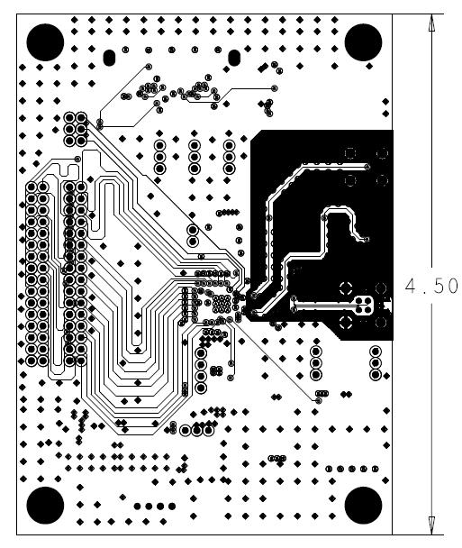
26 DS90UB913Q PCB Layout 26 Texas Instruments 11/19/2012
27 27 Texas Instruments 11/19/2012
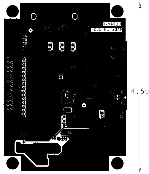
28 DS90UB914Q EVK Layout 28 Texas Instruments 11/19/2012

29 29 Texas Instruments 11/19/2012
FPD-Link III Serialize board (NV012-A) Hardware specifications. The 1st edition. Net Vision Co., Ltd.
 Hardware specifications. The 1st edition. Net Vision Co., Ltd.") FPD-Link III Serialize board (NV012-A) Hardware specifications The 1st edition Net Vision Co., Ltd. Revision history Version Date Content Charge 1 st edit. 2015/10/08 First edition creation H.Yamada 2
FPD-Link III Serialize board (NV012-A) Hardware specifications The 1st edition Net Vision Co., Ltd. Revision history Version Date Content Charge 1 st edit. 2015/10/08 First edition creation H.Yamada 2
FPD-Link Evaluation Kit User s Manual NSID FLINK3V8BT-85
 FPD-Link Evaluation Kit User s Manual NSID FLINK3V8BT-85 Rev 3.0 Page 1 of 25 Table of Contents INTRODUCTION... 3 CONTENTS OF EVALUATION KIT... 4 APPLICATIONS... 4 FEATURES AND EXPLANATIONS... TRANSMITTER...
FPD-Link III Deserializer Board FPI-954-A (Board model number NV015-A) Hardware Specification. Rev NetVision Co., Ltd.
 Hardware Specification. Rev NetVision Co., Ltd.") FPD-Link III Deserializer Board FPI-954-A (Board model number NV015-A) Hardware Specification Rev. NetVision Co., Ltd. Update History Revision Date Note 2018/04/12 New file (Equivalent to Japanese version
FPD-Link III Deserializer Board FPI-954-A (Board model number NV015-A) Hardware Specification Rev. NetVision Co., Ltd. Update History Revision Date Note 2018/04/12 New file (Equivalent to Japanese version
KNJN I2C bus development boards
 KNJN I2C bus development boards 2005, 2006, 2007, 2008 KNJN LLC http://www.knjn.com/ Document last revision on December 5, 2008 R22 KNJN I2C bus development boards Page 1 Table of Contents 1 The I2C bus...4
Nuvoton Touch Key Series NT1160 Datasheet
 Nuvoton Touch Series Datasheet The information described in this document is the exclusive intellectual property of Nuvoton Technology Corporation and shall not be reproduced without permission from Nuvoton.
KNJN I2C bus development boards
 KNJN I2C bus development boards 2005, 2006, 2007, 2008 fpga4fun.com & KNJN LLC http://www.knjn.com/ Document last revision on January 1, 2008 R12 KNJN I2C bus development boards Page 1 Table of Contents
SERDESUB-16OVT EVM User s Guide
 User s Guide SNLU108 July 2012 SERDESUB-16OVT EVM User s Guide TABLE OF CONTENTS TABLE OF CONTENTS... 1 1. DESCRIPTION... 2 2. KIT CONTENTS... 3 3. SYSTEM REQUIREMENTS... 3 4. SETUP INSTRUCTIONS... 4 5.
FPD-Link III Serializer Board FPO-953-A (Board model number NV022-A) Hardware Specification. Rev.1.0. NetVision Co., Ltd.
 Hardware Specification. Rev.1.0. NetVision Co., Ltd.") FPD-Link III Serializer Board FPO-953-A (Board model number NV022-A) Hardware Specification Rev. NetVision Co., Ltd. Update History Revision Date Note 2018/04/24 New file (Equivalent to Japanese version
FPD-Link III Serializer Board FPO-953-A (Board model number NV022-A) Hardware Specification Rev. NetVision Co., Ltd. Update History Revision Date Note 2018/04/24 New file (Equivalent to Japanese version
FPD-Link Ⅲ Serializer Board FPO-913A (Board model number NV021-A) Hardware Specification. Rev.1.0. NetVision Co., Ltd.
 Hardware Specification. Rev.1.0. NetVision Co., Ltd.") FPD-Link Ⅲ Serializer Board FPO-913A (Board model number NV021-A) Hardware Specification Rev.. NetVision Co., Ltd. Update History Revision Date Note 2018/06/11 New file (Equivalent to Japanese version
FPD-Link Ⅲ Serializer Board FPO-913A (Board model number NV021-A) Hardware Specification Rev.. NetVision Co., Ltd. Update History Revision Date Note 2018/06/11 New file (Equivalent to Japanese version
ArduCAM-M-2MP Camera Shield
 33275-MP ArduCAM-M-2MP Camera Shield 2MP SPI Camera Hardware Application Note Rev 1.0, Mar 2015 33275-MP ArduCAM-M-2MP Hardware Application Note Table of Contents 1 Introduction... 2 2 Typical Wiring...
USB-to-I2C. Ultra Hardware User s Manual.
 USB-to-I2C Ultra Hardware User s Manual https://www.i2ctools.com/ Information provided in this document is solely for use with the USB-to-I2C Ultra product from SB Solutions, Inc. SB Solutions, Inc. reserves
Win-I2CUSB Hardware User s Manual
 Win-I2CUSB Hardware User s Manual http://www.demoboard.com Information provided in this document is solely for use with the Win-I2CUSB product from The Boardshop. The Boardshop and SB Solutions, Inc. reserve
MAX96706 GMSL Deserializer Board GMI (Board model number NV013-B) Hardware Specification. Rev. 1.0
 Hardware Specification. Rev. 1.0") MAX96706 GMSL Deserializer Board GMI-96706 (Board model number NV013-B) Hardware Specification Rev. NetVision Co., Ltd. Update History Revision Date Note 2018/04/24 New file (Equivalent to Japanese version
MAX96706 GMSL Deserializer Board GMI-96706 (Board model number NV013-B) Hardware Specification Rev. NetVision Co., Ltd. Update History Revision Date Note 2018/04/24 New file (Equivalent to Japanese version
XS S ERIES TM PMB US TM O PTION C ARD
 XS Series PMBus Option Card XS S ERIES TM PMB US TM O PTION C ARD Document: 40110r01 1 Contents 1 Introduction 4 2 Option Card Connectors 4 2.1 PMBus Address..............................................
SmartFan Vortex. I2C Speed Control for 12 VDC Fans CONTROL RESOURCES INCORPORATED. The driving force of motor control & electronics cooling.
 The driving force of motor control & electronics cooling. SmartFan Vortex I2C Speed Control for 12 VDC Fans DC Controls P/N VOR5I400F SmartFan Vortex is an I2C fan speed control and alarm designed for
USB-to-I2C. Professional Hardware User s Manual.
 USB-to-I2C Professional Hardware User s Manual https://www.i2ctools.com/ Information provided in this document is solely for use with the USB-to-I2C Professional product from SB Solutions, Inc. SB Solutions,
Tutorial for I 2 C Serial Protocol
 Tutorial for I 2 C Serial Protocol (original document written by Jon Valdez, Jared Becker at Texas Instruments) The I 2 C bus is a very popular and powerful bus used for communication between a master
Modtronix Engineering Modular Electronic Solutions SBC28DC. Single board computer for 28 pin DIP PICs
 Modtronix Engineering Modular Electronic Solutions Single board computer for 28 pin DIP PICs Table of Contents 1 Introduction...2 2 Features...4 3 Expansion Connectors...5 3.1 Daughter Board Connectors...5
TPMC815 ARCNET PMC. User Manual. The Embedded I/O Company. Version 2.0. Issue 1.2 November 2002 D
 The Embedded I/O Company TPMC815 ARCNET PMC Version 2.0 User Manual Issue 1.2 November 2002 D76815804 TEWS TECHNOLOGIES GmbH Am Bahnhof 7 25469 Halstenbek / Germany Phone: +49-(0)4101-4058-0 Fax: +49-(0)4101-4058-19
SmartFan Fusion-4. Speed Control and Alarm for DC Fans CONTROL RESOURCES INCORPORATED. The driving force of motor control & electronics cooling.
 SmartFan Fusion-4 Speed Control and Alarm for DC Fans The driving force of motor control & electronics cooling. P/N FUS300-F DC Controls SmartFan Fusion-4 is a digital fan speed control and alarm that
JMY505G User's Manual
 JMY505G User's Manual (Revision 3.42) Jinmuyu Electronics Co. LTD 2011/6/28 Please read this manual carefully before using. If any problem, please mail to: jinmuyu@vip.sina.com Contents 1 Product introduction...
Manual iaq-engine Indoor Air Quality sensor
 Manual iaq-engine, Version 2.0 May 2011 (all data subject to change without notice) Manual iaq-engine Indoor Air Quality sensor Digital and analog I/O SMD type package Product summary iaq-engine is used
User s Manual. PCIe-FRM11 User s Manual (Rev 1.4)
") PCIe-FRM11 User s Manual Windows, Windows2000, Windows NT and Windows XP are trademarks of Microsoft. We acknowledge that the trademarks or service names of all other organizations mentioned in this document
PCIe-FRM11 User s Manual Windows, Windows2000, Windows NT and Windows XP are trademarks of Microsoft. We acknowledge that the trademarks or service names of all other organizations mentioned in this document
ONYX-MM-XT PC/104 Format Counter/Timer & Digital I/O Module
 ONYX-MM-XT PC/104 Format Counter/Timer & Digital I/O Module User Manual V1.4 Copyright 2009 Diamond Systems Corporation 1255 Terra Bella Avenue Mountain View, CA 94043 USA Tel (650) 810-2500 Fax (650)
MC20902-EVB. MC20902 D-PHY 5-Channel Master Transmitter Evaluation Board User's Guide PRELIMINARY DATASHEET. Version February 2014.
 C O N F MC20902 D-PHY 5-Channel Master Transmitter Evaluation Board User's Guide I D E N PRELIMINARY DATASHEET Version 1.00 T February 2014 I Meticom GmbH A L Meticom GmbH Page 1 of 14 Revision History
Summary. Introduction
 A 2 B - I 2 S MODULE - MODULE EVM SYSTEM A 2 B - I 2 S MODULE Summary SUPPORTS ANALOG DEVICES Off the shelf module for A 2 B interfacing to I 2 S and I 2 C devices Based on Analog Devices newest AD2428W
User Guide Feb 5, 2013
 HI 8435 32 Sensor Array with Ground/Open or Supply/Open Sensors and SPI interface. Evaluation Board 23351 Madero, Mission Viejo, CA 92691. USA. Tel: + 1 949 859 8800 Fax: + 1 949 859 9643 Email: sales@holtic.com
USB-to-I2C Basic. Hardware User s Manual.
 USB-to-I2C Basic Hardware User s Manual http://www.i2ctools.com/ Information provided in this document is solely for use with the USB-to-I2C product from SB Solutions, Inc. SB Solutions, Inc. reserves
ArduCAM USB Camera Shield
 ArduCAM USB Camera Shield User Guide Rev 1.0, April 2017 Table of Contents 1 Introduction... 2 2 Hardware Installation... 2 2.1 Primary Camera Interface... 2 2.2 Secondary Camera Interface... 3 3 Device
Grove Digital Extender 0059-GRVDE-DSBT/SF
 Features and Benefits: The board is an easy to use I2C controlled board that provides 8 Grove Digital I/O ports. 8 Connectors I2C controlled 3 total Grove I2C Connectors (2 spare) 8 GPIO pins 3.3V and
Exercise 2 I 2 C Management 1/7
 Exercise 2 I 2 C Management I²C uses only two bidirectional open-drain lines, Serial Data Line (SDA) and Serial Clock Line (SCL), pulled up with resistors. Typical voltages used are 5 V or 3.3 V. The I²C
or between microcontrollers)
") : Communication Interfaces in Embedded Systems (e.g., to interface with sensors and actuators or between microcontrollers) Spring 2016 : Communication Interfaces in Embedded Systems Spring (e.g., 2016
: Communication Interfaces in Embedded Systems (e.g., to interface with sensors and actuators or between microcontrollers) Spring 2016 : Communication Interfaces in Embedded Systems Spring (e.g., 2016
A0021. Overview. Features. Ordering Information. HSS Touch Signature IC 6 Input - I 2 C. Part Number Format: A X Y Z
 VSS NC NC VDD SDA SENSOR 2 SENSOR 1 ADD1 HSS Touch Signature IC 6 Input - I 2 C A0021 Overview The patented AlSentis A0021 Touch IC is a complete 1 6 input touch sensing solution. It includes all signal
Manual MB86R01. JADE Evaluation Board Extension Video Output. Version PA5.1 November 20, 2007
 1(20) Receiver: Info: M. Carstens-Behrens mycable GmbH Manual MB86R01 JADE Evaluation Board Extension Video Output Version November 20, 2007 http://www.fujitsu.com/emea/services/microelectronics 2(20)
1 Introduction Overview Quick Start Circuit Description Port Setting...5
 PI5USB30216C Demo Board Rev.A User Manual by Justin Lee Table of Contents 1 Introduction...2 2 Overview...2 3 Quick Start...4 4 Circuit Description...5 4.1 Port Setting...5 4.2 Mode Selection, I2C Address
HZX N03 Bluetooth 4.0 Low Energy Module Datasheet
 HZX-51822-16N03 Bluetooth 4.0 Low Energy Module Datasheet SHEN ZHEN HUAZHIXIN TECHNOLOGY LTD 2017.7 NAME : Bluetooth 4.0 Low Energy Module MODEL NO. : HZX-51822-16N03 VERSION : V1.0 1.Revision History
McMaster University Embedded Systems. Computer Engineering 4DS4 Lecture 6 Serial Peripherals Amin Vali Feb. 2016
 McMaster University Embedded Systems Computer Engineering 4DS4 Lecture 6 Serial Peripherals Amin Vali Feb. 2016 Serial Peripherals I2C Inter-IC Bus X/Y Coord. RGB data LCD config controller LCD data controller
A0061. Overview. Features. Ordering Information. HSS Touch Signature IC 15 Input - I 2 C. Part Number Format: A X Y Z
 Sensor5 ADD2 ADD1 SCL SDA Sensor6 Sensor7 Sensor1 Sensor0 Reset NC NC Sensor14 Sensor13 HSS Touch Signature IC 15 Input - I 2 C A0061 Overview The patented AlSentis A0061 Touch IC is a complete 1 15 input
5. What happens if we attempt to program a new frequency outside the specified speed grade of the device?
 Si57x FAQ Rev. 0.2 Overview This document is intended to address common questions about the Silicon Laboratories programmable oscillator Si570 XO and Si571 VCXO products. The term Si57x stands for both
EPT-200TMP-TS-U2 TMP102 Temperature Sensor Docking Board Data Sheet
 EPT-2TMP-TS-U2 TMP12 Temperature Sensor Docking Board Data Sheet This docking board is based on the TMP12 Temperature Sensor chip from Texas Instruments. It can measure the ambient temperature between
Pmod modules are powered by the host via the interface s power and ground pins.
 1300 Henley Court Pullman, WA 99163 509.334.6306 www.store. digilent.com Digilent Pmod Interface Specification 1.2.0 Revised October 5, 2017 1 Introduction The Digilent Pmod interface is used to connect
4.1 Design Concept Demonstration for Altera DE2-115 FPGA Board Demonstration for Cyclone III Development Board...
 CONTENTS CHAPTER 1 INTRODUCTION OF THE AHA-HSMC... 1 1.1 Features...1 1.2 About the KIT...2 1.3 Getting Help...3 CHAPTER 2 AHA CARD ARCHITECTURE... 4 2.1 Layout and Components...4 2.2 Block Diagram of
DS99R124Q-EVK FPD-Link II to FPD-Link Converter Evaluation Kit
 DS99R124Q-EVK FPD-Link II to FPD-Link Converter Evaluation Kit Rev 0.0 April, 2010 General Description The DS99R124Q-EVK converts FPD-link II to FPD-Link. It translates a high-speed serialized interface
IOX-16 User s Manual. Version 1.00 April Overview
 UM Unified Microsystems IOX-16 User s Manual Version 1.00 April 2013 Overview The IOX-16 Arduino compatible shield is an easy way to add 16 additional digital Input/Output (I/O) lines to your Arduino system.
CCS Technical Documentation NHL-2NA Series Transceivers. Camera Module
 CCS Technical Documentation NHL-2NA Series Transceivers Issue 1 07/02 Nokia Corporation NHL-2NA CCS Technical Documentation [This page left intentionally blank] Page 2 Nokia Corporation Issue 1 07/02 CCS
Prototyping Module Datasheet
 Prototyping Module Datasheet Part Numbers: MPROTO100 rev 002 Zenseio LLC Updated: September 2016 Table of Contents Table of Contents Functional description PROTOTYPING MODULE OVERVIEW FEATURES BLOCK DIAGRAM
GENERAL DESCRIPTION MC3635 FEATURES
 Quick Start Guide and Demo GENERAL DESCRIPTION The MC3635 is an ultra-low power, lownoise, integrated digital output 3-axis accelerometer with a feature set optimized for wearables and consumer product
SSD2805 MIPI Bridge Evaluation Kit User's Guide
 SSD2805 MIPI Bridge Evaluation Kit User's Guide TechToys Company Unit 12, 9/F, Block B Sun Fung Centre 88 Kwok Shui Road Tsuen Wan Hong Kong Tel: 852-28576267 Fax: 852-28576216 Web site: www.techtoys.com.hk
UM PCAL6524 demonstration board OM Document information
 Rev. 1 23 September 2015 User manual Document information Info Content Keywords OM13320 Fm+ development kit, OM13260 Fm+ I2C bus development board, OM13303 GPIO target board Abstract Installation guide
DS16EV5110-EVKD DVI Extender Demo Kit for DVI Cables
 DS16EV5110-EVKD DVI Extender Demo Kit for DVI Cables General Description The DS16EV5110-EVKD DVI Cable Extender Demo Kit provides a complete DVI system extension solution using National s DS16EV5110 -
Introduction to I2C & SPI. Chapter 22
 Introduction to I2C & SPI Chapter 22 Issues with Asynch. Communication Protocols Asynchronous Communications Devices must agree ahead of time on a data rate The two devices must also have clocks that are
HIGH-PRECISION COULOMB COUNTER. George Sandler, UNCC ECE
 HIGH-PRECISION COULOMB COUNTER George Sandler, UNCC ECE Abstract: For the purpose of monitoring current consumption of wireless communication in different modes a coulomb counter board has been designed.
MIPI Input Video Capture /Conversion Board [SVM-MIPI] Hardware Specification
![MIPI Input Video Capture /Conversion Board [SVM-MIPI] Hardware Specification](/thumbs/89/99939796.jpg "MIPI Input Video Capture /Conversion Board [SVM-MIPI] Hardware Specification") MIPI Input Video Capture /Conversion Board [SVM-MIPI] Hardware Specification Rev. NetVision Co., Ltd. Update History Revision Date Note 2018/04/24 New File(Equivalent to Japanese version 2.4) i Index 1.
MIPI Input Video Capture /Conversion Board [SVM-MIPI] Hardware Specification Rev. NetVision Co., Ltd. Update History Revision Date Note 2018/04/24 New File(Equivalent to Japanese version 2.4) i Index 1.
Application Note: AZD025 IQ Switch - ProxSense TM Series I2C Example Code for the IQS222
 1. Introduction Application Note: AZD025 IQ Switch - ProxSense TM Series I2C Example Code for the IQS222 The IQS222 uses a 100 KHz bi-directional 2-wire bus and data transmission protocol. The serial protocol
Raspberry Pi - I/O Interfaces
 ECE 1160/2160 Embedded Systems Design Raspberry Pi - I/O Interfaces Wei Gao ECE 1160/2160 Embedded Systems Design 1 I/O Interfaces Parallel I/O and Serial I/O Parallel I/O: multiple input/output simultaneously
RM24C64AF 64-Kbit 1.65V Minimum Non-volatile Fast Write Serial EEPROM I 2 C Bus
 64-Kbit 1.65V Minimum Non-volatile Fast Write Serial EEPROM I 2 C Bus Advance Datasheet Features Memory array: 64Kbit EEPROM-compatible non-volatile serial memory Single supply voltage: 1.65V - 2.2V 2-wire
DS1070K EconOscillator Programming Kit
 Rev 0; 5/04 DS070K EconOscillator Programming Kit General Description The DS070K EconOscillator programming kit is a complete hardware/software solution for programming Dallas Semiconductor s 2-wire EconOscillator
Copper SFP Transceiver
 Features Up to 1.25Gb/s bi-directional data links Hot-pluggable SFP footprint TX Disable and RX Los/without Los function Extended case temperature range (0 C to +70 C ) Fully metallic enclosure for low
GLC-T (1000BASE-T SFP) Datasheet
 Datasheet") GLC-T (1000BASE-T SFP) Datasheet Features Up to 1.25Gb/s bi-directional data links Hot-pluggable SFP footprint TX Disable and RX Los/without Los function Fully metallic enclosure for low EMI Low power
GLC-T (1000BASE-T SFP) Datasheet Features Up to 1.25Gb/s bi-directional data links Hot-pluggable SFP footprint TX Disable and RX Los/without Los function Fully metallic enclosure for low EMI Low power
MC3635 FEATURES GENERAL DESCRIPTION
 GENERAL DESCRIPTION MC3635 FEATURES The MC3635 is an ultra-low power, low noise, integrated digital output 3-axis accelerometer with a feature set optimized for wearables and the Internet of Moving Things
TIP815. ARCNET Controller. Version 1.0. User Manual. Issue September 2009
 The Embedded I/O Company TIP815 ARCNET Controller Version 1.0 User Manual Issue 1.0.7 September 2009 TEWS TECHNOLOGIES GmbH Am Bahnhof 7 25469 Halstenbek, Germany Phone: +49 (0) 4101 4058 0 Fax: +49 (0)
SSD1963 EVK Rev3B User s Guide
 SSD1963 EVK Rev3B User s Guide TechToys Company Unit 1807, Pacific Plaza, 410 Des Voeux Road West, Hong Kong Tel: 852-28576267 Fax: 852-28576216 Web site: www.techtoys.com.hk Version 1.0a Page 1 Table
ArduCAM-M-5MP Camera Shield
 ArduCAM-M-5MP Camera Shield 5MP SPI Camera User Guide Rev 1.0, Mar 2015 Table of Contents 1 Introduction... 2 2 Application... 2 3 Features... 3 4 Key Specifications... 3 5 Pin Definition... 3 6 Block
CprE 488 Embedded Systems Design. Lecture 4 Interfacing Technologies
 CprE 488 Embedded Systems Design Lecture 4 Interfacing Technologies Joseph Zambreno Electrical and Computer Engineering Iowa State University www.ece.iastate.edu/~zambreno rcl.ece.iastate.edu Never trust
The AMG5715A1B9 is designed to be powered using an AMG2001 standalone power supply.
 AMG5715A1B9 Instruction Manual Single Channel Video Transmit Unit with one Bi-directional Data Channel, two Uni-directional Alarms and one Bidirectional Audio Channel for a Singlemode Fibre Link The AMG5715A1B9
XSFP-SPT-PE-T1 Copper SFP Transceiver
 XSFP-SPT-PE-T1 Copper SFP Transceiver Features Up to 1.25GB/s bi-directional data links Hot-pluggable SFP footprint Extended case temperature range (0 C to +70 C ) Fully metallic enclosure for low EMI
DS1870 LDMOS BIAS CONTROLLER EV KIT
 GENERAL DESCRIPTION The DS1870 EV Kit provides hardware and Window s compatible software to simplify the evaluation of the DS1870 LDMOS Bias Controller. FEATURES Includes test socket for solderless connectivity
HFRD REFERENCE DESIGN High-Frequency XFP Host Board. Reference Design: (Includes Integrated RS-232 to I 2 C Conversion)
") Reference Design: HFRD-18.0 Rev. 7; 11/09 REFERENCE DESIGN High-Frequency XFP Host Board (Includes Integrated RS-232 to I 2 C Conversion) Reference Design: High-Frequency XFP Host Board Table of Contents
Reference Design: HFRD-18.0 Rev. 7; 11/09 REFERENCE DESIGN High-Frequency XFP Host Board (Includes Integrated RS-232 to I 2 C Conversion) Reference Design: High-Frequency XFP Host Board Table of Contents
S 27-Bit Parallel Interface S Rosenberger Connector (Cable Included) S Proven PCB Layout S Fully Assembled and Tested. Maxim Integrated Products 1
 S Proven PCB Layout S Fully Assembled and Tested. Maxim Integrated Products 1") 19-90; Rev 0; 9/09 MAX97/MAX98 Evaluation Kit General Description The MAX97/MAX98 evaluation kit (EV kit) provides a proven design to evaluate the MAX97 7-bit,.5MHz to MHz DC-balanced LVDS serializer and
19-90; Rev 0; 9/09 MAX97/MAX98 Evaluation Kit General Description The MAX97/MAX98 evaluation kit (EV kit) provides a proven design to evaluate the MAX97 7-bit,.5MHz to MHz DC-balanced LVDS serializer and
USER MANUAL EXPERIENCE INCREDIBLE PERFORMANCE V2.3
 USER MANUAL EXPERIENCE INCREDIBLE PERFORMANCE V2.3 CONTENTS 1 INTRODUCTION... 3 2 INTERFACE DESIGN... 4 2.1 Connectivity... 5 2.2 Analog Interface... 6 2.3 I 2 C Interface... 7 2.4 I 2 C Operations...
An Efficient Designing of I2C Bus Controller Using Verilog
 American International Journal of Research in Science, Technology, Engineering & Mathematics Available online at http://www.iasir.net ISSN (Print): 2328-3491, ISSN (Online): 2328-3580, ISSN (CD-ROM): 2328-3629
USER GUIDE. Atmel OLED1 Xplained Pro. Preface
 USER GUIDE Atmel OLED1 Xplained Pro Preface Atmel OLED1 Xplained Pro is an extension board to the Atmel Xplained Pro evaluation platform. The board enables the user to experiment with user interface applications
LM53X Development and Evaluation Product Family
 Development and Evaluation Family Revised Datasheet Version 13/MAR/2018 1.0 Overview The is the development and evaluation product family for the LM930 / LM931 Bluetooth low energy module. A great starting
Hello, and welcome to this presentation of the STM32 I²C interface. It covers the main features of this communication interface, which is widely used
 Hello, and welcome to this presentation of the STM32 I²C interface. It covers the main features of this communication interface, which is widely used to connect devices such as microcontrollers, sensors,
Digilab 2 XL Reference Manual
 125 SE High Street Pullman, WA 99163 (509) 334 6306 (Voice and Fax) www.digilentinc.com PRELIMINARY Digilab 2 XL Reference Manual Revision: May 7, 2002 Overview The Digilab 2 XL (D2XL) development board
Using an Analog Devices AD774X Capacitance-to-Digital Converter for Differential Button Sensor Operation
 Using an Analog Devices AD774X Capacitance-to-Digital Converter for Differential Button Sensor Operation Eric Otte April 3 rd, 2010 ECE 480 Executive Summary: Capacitive sensors are increasingly being
JU1 JU6, JU15 JU20. Maxim Integrated Products 1
 9-9; Rev 0; /0 MAX9 Evaluation Kit General Description The MAX9 evaluation kit (EV kit) contains a flowthrough low-voltage differential signaling (LVDS) quad differential line driver (MAX9) and receiver
MPU-6000/MPU Axis Evaluation Board User Guide
 MPU-6000/MPU-6050 9-Axis Evaluation Board User Guide InvenSense, Inc., 1197 Borregas Ave., Sunnyvale, Ca 94089, USA 1 AN-MPU-6000EVB-00 Table of Contents 1. REVISION HISTORY... 3 2. PURPOSE... 4 2.1 USAGE...
Amarjeet Singh. January 30, 2012
 Amarjeet Singh January 30, 2012 Website updated - https://sites.google.com/a/iiitd.ac.in/emsys2012/ Lecture slides, audio from last class Assignment-2 How many of you have already finished it? Final deadline
SH1030 Rev Introduction. Ultra low power DASH7 Arduino Shield Modem. Applications. Description. 868 MHz. Features
 SH1030 Rev. 1.2 Applications Wireless sensor network Data acquisition equipment Security systems Industrial monitor and control Internet of things (IoT) Ultra low power DASH7 Arduino Shield Modem 868 MHz
CompuScope 3200 product introduction
 CompuScope 3200 product introduction CompuScope 3200 is a PCI bus based board-level product that allows the user to capture up to 32 bits of singleended CMOS/TTL or differential ECL/PECL digital data into
Accelerometer board. EB068
 Accelerometer board www.matrixtsl.com EB0 Contents About this document Board layout General information Testing this product Circuit description 5 Circuit diagram Copyright 0 Matrix TSL About this document
34 Series EEPROM Application Note. 1. Introduction. 2. Power supply & power on reset
 1. Introduction his application note provides assistance and guidance on how to use GIANEC I 2 C serial EEPROM products. he following topics are discussed one by one: Power supply & power on reset Power
DESIGNING OF INTER INTEGRATED CIRCUIT USING VERILOG
 DESIGNING OF INTER INTEGRATED CIRCUIT USING VERILOG DISHA MALIK Masters of Technology Scholar, Department of Electronics & Communication Engineering, Jayoti Vidyapeeth Women s University, Jaipur INDIA
APPLICATION NOTE. Atmel QT4 Xplained Pro User Guide ATAN0114. Preface
 APPLICATION NOTE Atmel QT4 Xplained Pro User Guide ATAN0114 Preface Atmel QT4 Xplained Pro kit is an extension board that enables evaluation of self-capacitance mode proximity and touch using the peripheral
VLSI AppNote: VSx053 Simple DSP Board
 : VSx053 Simple DSP Board Description This document describes the VS1053 / VS8053 Simple DPS Board and the VSx053 Simple DSP Host Board. Schematics, layouts and pinouts of both cards are included. The
CMOS OV5640C AF Camera Module 1/4-Inch 5-Megapixel Module Datasheet
 CMOS OV5640C AF Camera Module 1/4-Inch 5-Megapixel Module Datasheet Rev 1.0, June 2015 Table of Contents 1 Introduction... 2 2 Features... 3 3 Key Specifications... 3 4 Block Diagram... 4 5 Application...
PI5USB30213AXEA Demo Board Rev.B User Manual
 PI5USB30213AXEA Demo Board Rev.B User Manual Table of Contents 1 Introduction... 2 2 Overview... 2 3 Quick Start... 4 3.1 Source(DFP) Mode... 4 3.2 Battery-powered Sink(UFP) Mode... 5 3.3 Bus-powered Sink(UFP)
Chapter 1 Introduction Features Getting Help Chapter 2 Architecture Block Diagram... 6
 1 CONTENTS Chapter 1 Introduction... 3 1.1 Features... 3 1.2 Getting Help... 4 Chapter 2 Architecture... 5 2.1 Block Diagram... 6 Chapter 3 Pin Description... 8 3.1 HSMC Expansion Connector... 8 Chapter
SmartFan Cirrus-9. Speed Control and Alarm for 4-Wire Fans CONTROL RESOURCES INCORPORATED. The driving force of motor control & electronics cooling.
 SmartFan Cirrus-9 Speed Control and larm for 4-Wire Fans The driving force of motor control & electronics cooling. P/N 4WR9C00-F DC Controls SmartFan Cirrus-9 is a digital fan speed control and alarm that
I/O1 Xplained Pro. Preface. Atmel MCUs USER GUIDE
 Atmel MCUs I/O1 Xplained Pro USER GUIDE Preface Atmel I/O1 Xplained Pro is an extension board to the Atmel Xplained Pro evaluation platform. I/O1 Xplained Pro is designed to give a wide variety of functionality
RFID A1 Module User Manual V1.183
 RFID A1 Module User Manual V1.183 Table of Contents 1 Introduction... 4 1.1 Device Overview... 4 1.2 Pinout... 5 1.3 Application... 6 2 Electrical Characteristics... 7 2.1 Test Conditions... 7 2.2 Absolute
PI5USB30216DXUA Demo Board Rev.B User Manual
 PI5USB30216DXUA Demo Board Rev.B User Manual Table of Contents Measurement by: NA Report by: Lee, Justin 1 Introduction... 2 2 Overview... 2 3 Quick Start... 4 3.1 Source(DFP) Mode... 4 3.2 Battery-powered
Level Shifter. for. Hardware User s Manual.
 Level Shifter for USB-to to-i2c Hardware User s Manual https://www.i2ctools.com/ Information provided in this document is solely for use with the I2C and SPI Level Shifter from SB Solutions, Inc. SB Solutions,
1. Features and Benefits
 1. Features and Benefits Single die, low cost 16x4 pixels IR array Factory calibrated absolute PTAT temperature sensor for measuring die temperature Separate channel for connecting additional IR sensor
Parallel Data Transfer. Suppose you need to transfer data from one HCS12 to another. How can you do this?
 Introduction the Serial Communications Huang Sections 9.2, 10.2, 11.2 SCI Block User Guide SPI Block User Guide IIC Block User Guide o Parallel vs Serial Communication o Synchronous and Asynchronous Serial
Stepper 6 click. PID: MIKROE 3214 Weight: 26 g
 Stepper 6 click PID: MIKROE 3214 Weight: 26 g Stepper 6 click is the complete integrated bipolar step motor driver solution. It comes with the abundance of features that allow silent operation and optimal
IMU Axis Gyro Evaluation Board Application Note
 IMU-3000 3-Axis Gyro Evaluation Board Application Note A printed copy of this document is NOT UNDER REVISION CONTROL unless it is dated and stamped in red ink as, REVISION CONTROLLED COPY. InvenSense,
RS485 3 click. How does it work? PID: MIKROE-2821
 RS485 3 click PID: MIKROE-2821 RS485 3 click is an RS422/485 transceiver Click board, which can be used as an interface between the TTL level UART and the RS422/485 communication bus. It features a full-duplex
Spartan-II Demo Board User s Guide
 Spartan-II Demo Board User s Guide Version.2 May 200 Overview The Spartan-II Demo Board is a low cost evaluation platform for testing and verifying designs based on the Xilinx Spartan-II family of FPGA