Introduction to microcontrollers
|
|
|
- Milo Patterson
- 5 years ago
- Views:
Transcription
1 Page 1
2 Page 2 Contents Introduction 2 Worksheet 1 - Switch on the LED 3 Worksheet 2 - Make the LED flash 5 Worksheet 3 - Keep the LED lit for a short time 7 Worksheet 4 - Set up a latch 9 Worksheet 5 - Lighting sequence 11 Worksheet 6 - The AND gate 13 Worksheet 7 - A logic system 15 Worksheet 8 - Is it too dark? 17 Worksheet 9 - A tone generator 19 Worksheet 10 - Counting 21 User Guide 23


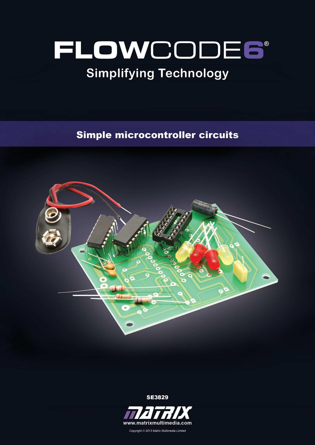
3 Page 3 Introduction The hardware: Reset button 5V 5V sockets sock- PIC microcontroller Prototype board USB connector Crystal oscillator Connections to I/O bits 0V sockets Sets of five holes all connected underneath Some details: The USB connector is used to connect the board to a computer, so that the microcontroller can be programmed. The connection also provides electrical power for the board. The PIC microcontroller stays in its socket. It can be replaced, if damaged, using a chip extractor, or by gently easing up each end in turn using a screwdriver. Once programming is completed, the Reset button is pressed to start the program. The crystal oscillator provides clock pulses to the microcontroller, synchronising its actions. The prototype board allows electronic components to be connected to the microcontroller, using 0.6mm wire plugged into the I/O (input / output) sockets. The holes in the prototype board are arranged in sets of five. These five are connected together by metal clips underneath the board. Electrical power can be connected to the prototype board, using 0.6mm wires plugged into 5V and 0V sockets. Using the worksheets: The worksheets focus on car-based applications, as are very widely used in automotive systems. However, the examples have a much broader applicability. The User Guide at the end of the module details all the steps needed to build the hardware, to program and to test the system. Please refer to these when necessary.
4 Page 4 Worksheet 1 Switch on the LED In today s world, we use more and more. These marvels of modern electronics are all-pervading, yet their use is so subtle that we often use them without realising it. Billions are sold every year! We use them in devices such as: the security token device used in on-line banking ; mobile phones, to set up and oversee our calls; microwave ovens to control the display and operation; engine management systems in our cars - increasingly we are driving-by-wire ; digital cameras to control the focussing and shutter control; television remote controls. This worksheet introduces a very simple application of a microcontroller - to turn on the car s sidelight when the switch is operated. The program: Build the Flowcode program, adding a PCB Switch and a LED 5mm Unmounted to the dashboard panel. Connect the switch to PORT A bit 0, and the LED to B bit 0. Configure the components as follows: Display name Repeat Loop while 1 Test Loop at the Start Display name Variable Input from Read the switch switch PORT A Single Bit 0 Display name Variable Output to Make it control the LED switch PORT B Single Bit 0 Save the Flowcode program. Simulate it to check that it works. Now, compile it to the chip. Build the circuit shown on the next page.
5 Page 5 Worksheet 1 Switch on the LED The circuit: Build the circuit, shown below, on the prototype board section of the hardware. Notice the power supply connections to the prototype board! The red wire connects the switch to the +5V socket. The switch is then connected through the resistor to 0V - a bridge of black wire connects the resistor to the long black wire plugged into 0V. The switch forms a voltage divider with the 1kΩ resistor (brown / black / red). The flat edge of the switch is on the side indicated in the diagram. Use this to ensure that it is connected correctly. The LED represents the car s sidelight bulb. Make sure that it is plugged in the right way round! Look for the flat edge on the skirt of the LED, or the shorter of the two legs. The short leg is connected through the resistor to 0V. The LED is protected by a 470Ω resistor (yellow / purple / brown). Test the circuit by pressing the switch, and then releasing it. You should find that it switches the LED on and off. What to do next: Modify the program so that the switch lights two sidelights, represented by two LEDs, one connected to B bit 0 and the other to B bit 1.


6 Worksheet 2 Make the LED flash Page 6 The loop function appears in all the worksheets. It makes the program cycle through repeatedly. For us, it allows us to observe what happens more easily, as each of the steps in the program lasts only microseconds. This worksheet introduces another common use of a microcontroller - to make a lamp flash on and off repeatedly, as in a car indicator (turn signal.) The program: Build the Flowcode program, adding a LED 5mm Unmounted to the dashboard panel. Connect the LED to PORT B bit 0. Configure the components as follows: Display name Repeat Loop while 1 Test Loop at the Start Display name Switch LED off Value 0 PORT B Output to Single Bit 0 Display name Wait for 1s Delay value 1 second Display name Switch LED on Value 1 PORT B Output to Single Bit 0 Save the Flowcode program. Simulate it to check that it works. Now, compile it to the chip. Build the circuit shown on the next page.

7 Worksheet 2 Make the LED flash Page 7 The circuit: Build the circuit, shown below, on the prototype board. Make sure that the LED, representing the car indicator lamp, is plugged in the right way round! If unsure how to do this, look back at the details on the previous worksheet. The LED is protected by a 470Ω resistor (yellow / purple / brown). Notice that there is no connection to the 5V socket this time. The LED is powered from the output of the microcontroller. The resistor is connected to 0V by the long black wire, completing the circuit. Test the circuit. The LED should flash on and off continuously - on for a second, then off for a second. What to do next: Modify the program so that the LED flashes twice as fast.

 is stored in a variable called switch.")


8 Worksheet 3 Keep the LED lit for a short time Page 8 The microcontroller can respond to changes in its surroundings. To do this, it takes in information via Input functions. In this case, it monitors the state of a switch, connected to A, bit 0. The information from the switch ( on or off ) is stored in a variable called switch. (The User Guide at the back of the module gives more information about using variables. This worksheet shows how to set up another common application - a lamp that stays on for a short time when triggered - a car courtesy light, for example. The program: Build the Flowcode program, adding a PCB Switch and a LED 5mm Unmounted to the dashboard panel. Connect the switch to PORT A bit 0, and the LED to B bit 0. Configure the Loop icon as previously. Set up the other components as follows: Display name Read the switch Variable switch PORT A Input from Single Bit 0 Display name Is it pressed? If switch=1 Display name Switch on LED Value 1 PORT B Output to Single Bit 0 Display name Wait for 10 s Delay value 10 seconds Display name Switch off LED Value 0 PORT B Output to Single Bit 0 Save the Flowcode program. Simulate it to check that it works. Now, compile it to the chip. Build the circuit shown on the next page.
9 Page 9 Worksheet 3 Keep the LED lit for a short time The circuit: Build the circuit, shown below, on the prototype board. It is identical to the one you built for worksheet 1. Notice the wire that takes information from the switch unit, and inputs it into A, bit 0 of the microcontroller! The switch represents a car door switch. It forms a voltage divider with the 1kΩ resistor (brown / black / red). The LED represents the car s courtesy light. Make sure that it is plugged in the right way round! It is protected by a 470Ω resistor, (yellow / purple / brown). Test the circuit by pressing and releasing the switch. The LED should light for ten seconds and then turn off. What to do next: Modify the program so that the LED stays on for 5 seconds when the switch is pressed.


10 Worksheet 4 Set up a latch Page 10 In this application, the microcontroller turns on an alarm under the right conditions. Then, the program uses an Output function to provide power to one of its output connections. This worksheet shows how to set up a latch. It uses two switches but each has a specific function. One switch turns on (sets) the alarm, an LED. in this system, and the other then turns it off (resets it.) The program: Build the Flowcode program. Add two PCB Switches and a LED 5mm Unmounted to the dashboard panel. Connect one switch to PORT A bit 0, the second to PORT A bit 1, and the LED to B bit 0. Add labels to identify the switches. Configure the Loop and first Input icon as before. Set up the other components as follows: Display name Is it pressed? If switch=1 Display name Switch on LED Value 1 PORT B Output to Single Bit 0 Display name Read switch A1 Variable reset PORT A Input from Single Bit 1 Display name Is it pressed? If reset=1 Display name Switch off LED Value 0 PORT B Output to Single Bit 0 that it works. Switch A0 is known as the Set switch, and A1 as the Reset switch. Now, compile it to the chip. Build the circuit shown on the next page. Save the Flowcode program. Simulate it to check
.")
11 Worksheet 4 Set up a latch Page 11 The circuit: Build the circuit, shown below, on the prototype board. The LED represents the alarm active warning light. Make sure that it is plugged in the right way round! It is protected by a 470Ω resistor, (yellow / purple / brown). Again, the switches form voltage dividers with the 1kΩ resistors (brown / black / red). The flat edges of the switches are indicated in the diagram. Use this information to connect the switches correctly. Test it by pressing switch A0 (the Set switch,) and then switch A1(the Reset switch). Does it matter how many times you press switch A0? Does it matter how many times you press switch A1? What to do next: Modify the program so that a second LED is turned on until switch A0 is pressed, and then lights again when switch A1 is pressed.


12 Worksheet 5 Set up a lighting sequence Page 12 Control systems often create sequences of operation, whether controlling motors, valves etc. In this worksheet, the microcontroller creates a simple light sequence. The program uses delay functions to allow each stage to remain long enough to be seen. One example of a lighting sequence is that provided by traffic lights, though these are more sophisticated than the simple LEDs used here. The program: Build the Flowcode program, adding three LED 5mm Unmounted s to the dashboard panel. Connect one LED to PORT B bit 0, the second to PORT B bit 1, and the third to B bit 2. Configure the Loop icon as in previous programs, and set up the other components as follows: Display name Switch off all LEDs Value 0 PORT B Output to Entire Display name Delay Delay value 1 second Display name Switch on 1st LED Value 1 PORT B Output to Single Bit 0 Display name Switch on 2nd LED Value 1 PORT B Output to Single Bit 1 Save Flowcode pro- the gram. Display name Switch on 3rd LED Value 1 PORT B Output to Single Bit 2 Simulate it to check that it works. Now, compile it to the chip. Build the circuit shown on the next page.
, bit 1 (B1) and bit 2 (B2).")
13 Page 13 Worksheet 5 Set up a lighting sequence The circuit: Build the circuit, shown below, on the prototype board. The three LEDs are powered from separate output connections on B of the microcontroller, called bit 0 (B0), bit 1 (B1) and bit 2 (B2). Notice the black wires that make up the 0V connection to these LEDs! Make sure that the LEDs are plugged in the right way round! Each LED is protected by a 470Ω resistor, (yellow / purple / brown). Test the circuit by pressing the Reset button and watching the sequence that follows. What to do next: Modify the program so that a switch must be pressed to make the sequence start.


14 Worksheet 6 Set up an AND logic gate Page 14 Microcontrollers can take in information from the outside world and make decisions based on it. Part of this can involve using calculation functions, which perform arithmetic and, as in this case, logic operations. Several separate calculations can be included in the same icon, as the illustration shows. In this worksheet, the car headlamps come on only if the ignition switch AND the headlamp switch are turned on. The program: Build the Flowcode program, adding two PCB Switches and a LED 5mm Unmounted to the dashboard panel. Connect one switch to PORT A bit 0, the second to PORT A bit 1, and the LED to B bit 0. Add labels to identify the switches. Configure the Loop icon as in previous programs, and set up the other components as follows: Display name Read switch A0 Variable ina PORT A Input from Single Bit 0 Display name Read switch A1 Variable inb PORT A Input from Single Bit 1 Display name AND them Calculation result = ina AND inb Display name Output the result Variable result PORT B Output to Single Bit 0 Save the Flowcode program. Simulate it to check that it works. Now, compile it to the chip. Build the circuit shown on the next page.
15 Worksheet 6 Set up an AND logic gate Page 15 The circuit: Build the circuit, shown below, on the prototype board. Switch A0 represents the ignition switch, and A1 the headlamp switch. The switches form voltage dividers with the 1kΩ resistors, (brown / black / red). Notice the red wires that connect the switches to the +5V supply, and the wires that take information from the switch units to the microcontroller via sockets A0 and A1. The LED represents the headlamp. Make sure that it is plugged in the right way round! It is protected by a 470Ω resistor, (yellow / purple / brown). Test the circuit by pressing one or both switches in various combinations. The LED should light only when both switches are pressed. What to do next: Modify the program to set up an OR gate, where the LED lights if either switch A0 OR A1 OR both is/are pressed. This arrangement could be used to turn on the car s courtesy light when either front door is opened.

 but has not fastened the seat belt.")


16 Worksheet 7 Set up a logic system Page 16 The previous worksheet showed how to set up a straightforward logic function, the AND gate. Microcontrollers can do far more powerful tasks. This time, the car seat-belt warning sign will light when the ignition switch is turned on, someone is sitting on the passenger seat (and the pressure switch inside it,) but has not fastened the seat belt. The program: Build the Flowcode program to light the LED only when switches A0 AND A1 are pressed AND switch A2 is NOT pressed. Add three PCB Switches and a LED 5mm Unmounted to the dashboard panel. Connect one switch to PORT A bit 0, the second to PORT A bit 1, the third to PORT A bit 2 and the LED to B bit 0. Add labels to identify the switches. Configure the Loop icon as in previous programs, and set up the other components as follows: Display name Read switch A0 Variable ina PORT A Input from Single Bit 0 (Set up the other Input icons in the same way so that the variable inb contains the state of switch A1, and inc that of A2.) Display name Check the combination Calculation result = ina AND inb AND NOT inc Save the Flowcode program. Display name Output the result Variable result PORT B Output to Single Bit 0 Simulate it to check that it works. Now, compile it to the chip. Build the circuit shown on the next page.
17 Worksheet 7 Set up a logic system Page 17 The circuit: Build the circuit, shown below, on the prototype board. This time there are three switches. Switch A0 represents the ignition switch, A1 the pressure switch, inside the passenger seat, and A2 the seat-belt switch that indicates when the belt is fastened. They form voltage dividers with the 1kΩ resistors, (brown / black / red). Notice the three red wires that connect the switch units to the +5V supply, and the three wires that take information from the switch units to the microcontroller via sockets A0, A1 and A2. The LED represents the seat belt warning light. Make sure that it is plugged in the right way round! It is protected by a 470Ω resistor, (yellow / purple / brown). Test the circuit by pressing the switches in various combinations. The LED should light only when switches A0 and A1 are pressed, (ignition on, and a passenger present,) and A2 is not pressed (seat belt not fastened.) What to do next: Modify the program so that the LED lights if switch A1 is pressed provided that switches A0 and A2 are NOT pressed.


 Display name If: Too bright?")
18 Worksheet 8 Is it too dark? Page 18 Many cars now have automatic headlights that switch on when the light-level outside falls too far. That is another decision that the microcontroller can make, using information from a light-sensing unit. It involves use of a decision element in the program. In its simplest form, as used here, it makes a Yes/No decision. Is it dark, or not? It makes this decision based on information from the lightsensing unit, contained in a variable called light. The program: Build the Flowcode program to turn on the LED only when little light shines on the LDR. Add an ADC dial and a LED 5mm Unmounted to the dashboard panel. The ADC dial represents the light-sensing unit. During simulation, turning up the pointer represents more and more light shining on the LDR. Connect it to channel An 0. Connect the LED to B bit 0. Configure the Loop icon as usual, and set up the other components as follows: Display name Component Macro Return Value Sample light level adc_dial1 GetInt light (Int variable) Display name If: Too bright? light<100 Display name Switch off LED Value 0 PORT B Output to Single Bit 0 (Set up the other Output icon in a similar way, to output a value of 1 to B0, to turn on the LED.) Save the Flowcode program. Simulate it to check that it works. Turn the pointer on the dial to check that it controls the state of the LED. Now, compile it to the chip. Build the circuit shown on the next page.

19 Worksheet 8 Is it too dark? Page 19 The circuit: Build the circuit, shown below, on the prototype board. The LDR, (light-dependent resistor,) can be connected either way round. Be careful not to snap off the legs through excessive bending. It forms a voltage divider with the variable resistor, made from a pot (potentiometer.) The three legs of the pot each go into a different row of the prototype board, even though only two are connected to the circuit. The LED represents the headlight. Make sure that it is plugged in the right way round! It is protected by a 470Ω resistor, (yellow / purple / brown). Test the circuit by shading the LDR with your hand. When dark enough, the microcontroller will switch on the LED. (You may have to adjust the variable resistor to make this happen.) What to do next: Modify the program so that the LED operates the other way round - turns on in bright light, and off when it gets dark.


 Connect one switch to PORT A bit 0, the second to PORT A bit 1, and the LED to B bit 0.")

20 Worksheet 9 Set up a tone generator Page 20 In this worksheet, a rapidly changing signal is fed to a sounder, a solid-state device which vibrates when it receives such a signal. The result can be an audible sound. The application this time is a two-tone horn, where the note produced depends on which of the two switches is pressed. This decision is made using a switch icon. In this case, there are two possible outcomes - notes of different tones. The program: Build the Flowcode program adding two PCB Switches and a LED 5mm Unmounted to the dashboard panel. Notice the use of the Switch icon to allow choice of notes. (The LED represents the sounder in simulation.) Connect one switch to PORT A bit 0, the second to PORT A bit 1, and the LED to B bit 0. Add labels to identify the switches. Configure the Loop icon, Output icons and the Delay icons as before, and set up the other components as follows: Display name Variable Input from Read input note PORT A Entire Display name Which note? Switch note Cases 1 2 Save the Flowcode program. Simulate it to check that it works. Now, compile it to the chip. Build the circuit shown on the next page
 and the black wire connected to 0V.")
21 Worksheet 9 Set up a tone generator Page 21 The circuit: Build the circuit, shown below, on the prototype board. The sounder represents the car horn. It must be connected the right way round, with the red wire nearer to the positive power supply (from socket B0 in this case,) and the black wire connected to 0V. Switches A0 and A1 are used to select the two tones. They form voltage dividers with the 1kΩ resistors, (brown / black / red). Notice the red wires that connect the switch units to the +5V supply, and the wires that take information from the switch units to the microcontroller via sockets A0 and A1. Test the circuit by pressing each switch in turn and noticing the tones that are produced. What to do next: Modify the program so that it produces a third note when both switches are pressed at the same time.


22 Worksheet 10 Counting Page 22 In modern vehicle engine management, one important factor is the engine speed. An electronic control unit counts pulses generated by a sensor attached to the rotating engine. The result is displayed on the rev counter, also called tachometer. This worksheet illustrates the principle behind this. It uses Connection points and a decision icon to make the program wait until the switch is pressed. The result is shown as a binary count on three LEDs. The program: Build the program, adding three LED 5mm Panel s and a PCB Switch to the dashboard panel. Connect one LED to PORT B bit 0, the second to PORT B bit 1, and the third to B bit 2. Connect the switch to A, bit 0. Here are the configuration details for some icons. Others you should be able to set up for yourself. Display name Start again Label A Display name Is it pressed? If switch = 1 Display name Jump to... Go back A:A Display name Check progress If count < 7 Display name Reset Calculation count = 0 (The 100 ms delay means that any contact bounce within 100ms is ignored.) Save the Flowcode program and simulate it to check that it works. Display name Add one to count Calculation count = count + 1
23 Page 23 Worksheet 10 Counting The circuit: Build the circuit, shown below, on the prototype board. The switch forms a voltage divider with the 1kΩ resistor, and sends information to the microcontroller via the socket A0. The number of times the switch is pressed is shown in binary on the three LEDs. This means that the LED attached to socket B0 shows units ; the one attached to socket B1 shows two s and that attached to socket B2 shows four s. If all three are lit, the count is = 7. Make sure that the LEDs are plugged in the right way round! They are protected by 470Ω resistors, as usual. Test the circuit by pressing the switch a number of times, and observing the resulting effect on the LEDs. Eventually, the count will return to zero (i.e. all LEDs turned off,) and then the count starts again. What to do next: Modify the program so that it always starts showing a count of zero.
24 Page 24 User Guide About this course Introduction The course is essentially a practical one. The ECIO hardware makes it simple and quick to program and construct microcontroller circuits. Aim The course introduces the graphical programming language Flowcode 6, and its use in programming PIC. Prior Knowledge None needed. Learning Objectives On successful completion of this course, you will be able to: run the Flowcode 6 application; select a target microcontroller for it; create a Flowcode flowchart by adding and configuring the following icons: loop; input; output; decision; delay; calculation; switch; connection points; component macros. create and use variables within the Flowcode program; open the Dashboard Panel and add and configure components on it; use on-screen simulation to debug the Flowcode program save the Flowcode flowchart; compile the Flowcode program into machine code; link the ECIO board to a computer and transfer the program; test a Flowcode program using hardware connected to the microcontroller.
25 Page 25 User Guide What the student will need: To complete the ECIO course, the student will need the following equipment: 1 ECIO baseboard, with PIC microcontroller 3 1kΩ resistors 3 PCB switches 1 light-dependent resistor 1 10kΩ potentiometer 3 LEDs 3 470Ω resistors 1 sounder lengths of 0.6mm single strand wire. Time: It will take students between four to six hours to complete the ten worksheets. Taking it further: Once you have completed these worksheets, you will want to experiment with your own programs. The Step-by-step guide, on the pages that follow, provides a basis for these. Use the examples in worksheets to help when adding hardware to the prototype board. These cover a large number of hardware configurations. They show circuits with: a single LED; a switch and one LED; two switches and one LED; three switches and one LED; three LEDs; an analogue sensor (via the ADC dial) and one LED; one switch and three LEDs; two switches and a sounder.. Further information: This course contains all the information you need to gain a firm foundation in the use of Flowcode 6 with the ECIO hardware. Once you have mastered this introduction to Flowcode 6, you are urged to look at the extensive volume of information and examples contained in the Matrix wiki, found at to expand your knowledge and experience.
26 Page 26 User Guide Step-by-step Guide to Flowcode 6 flowcharts: 1. Open Flowcode 6: When the Flowcode application starts, you are presented with four options: New project; Open a template; Launch Flowcode Help; Open an existing Flowcode project. Click on New project. 2. Select the target microcontroller: The Project Options screen opens. Click on the Misc tab, and then on the ECIO-28 option. Then click on OK 3. Add the icons: A new flowchart appears. If the System Panel appears on the screen, delete it by clicking on the X in the top righthand corner, or by opening the View menu and de-selecting System Panel. Down the left-hand edge of the workspace is the strip of possible icons. Click and drag the ones you want to make up the flowchart. 4. Configure each icon: Double-click on each icon in turn, and use information like that given in the worksheets to complete the configuration dialogue box. Click on OK after completing each. 5. Open the Dashboard Panel: Open the View menu, and click on the Dashboard Panel option. 6. Add the components: Items such as switches, and the ADC dial are found in the Inputs toolbox. The LEDs and sounders are found in the Outputs toolbox. Find the component you want and click on the down arrow just to the left of its name. Select the Add to dashboard panel option.


27 Page 27 User Guide Step-by-step Guide to the Worksheets - continued...: 7. Configure properties of components: Move the cursor over the component, and right-click the mouse. The Properties panel for the component appears. The important one for these worksheets is the Connections property, shown on the right. Click on the text alongside the Connection item, (here Unconnected ) and a diagram of the chosen microcontroller chip appears. Select the pin to connect the component by: selecting the port and bit from the two drop-down lists; or clicking on the pin on the image of the chip. 8. Simulate the program: You can test whether your Flowcode program works by simulating it on-screen. To simulate a flowchart: select the 'Run' option from the 'Debug' menu; or click the 'Run' button on the main toolbar (or press F5). Flowcode will go into simulation mode and will start to execute the program in the flowchart. A red rectangle indicates the next icon to be executed. Simulations can be paused or stopped by selecting either the 'Pause' or 'Stop' options from the 'Debug' menu or selecting them from the simulation section of the main toolbar. Alternatively, you can simulate the flowchart step by step, using the 'Step Into' function by pressing F8. You can also 'Step Over' icons by pressing Shift+F8. All these options can be accessed from the 'Debug' menu or by clicking the buttons on the main toolbar. Run Pause Stop Step into Step over
28 Page 28 User Guide Step-by-step Guide to the Worksheets - continued: 9. Save the flowchart: Flowcharts must be saved before they can be downloaded to the microcontroller. To save the flowchart: select either the Save or Save As option from the File menu; or click the button on the main toolbar. 10. Connect the board to the PC: Connect the USB socket on the board to the USB port of a computer. This allows the program to be transferred from the computer to the PIC microcontroller, and also delivers electrical power to the board. 11. Compile the flowchart and transfer it to the chip: The next step is to compile the Flowcode program, (convert it into machine code,) and then transfer it to the microcontroller. To do so: select the 'Compile to Chip' option from the 'Build' menu; or click the Compile to Chip icon on the toolbar. 12. Test the program using the hardware: Press the Reset switch on the ECIO board. Now use the mounted switches and LEDs etc. to confirm that the program does what you want it to do.

29 Page 29 User Guide Additional information: Resistor colour code: It is useful to be able to identify resistors, using the resistor colour code. They often come with coloured bands across their body to show the value of the resistance. Each colour represents a number, as shown in the table. Black Brown Red Orange Yellow Green Blue Purple Grey White To read the colour code, start from the opposite end to the gold or silver band: Write down the number shown by the first colour band, and then the second colour band. Add the number of 0 s shown in the next band (e.g for red, add two 0 s.) The final band (usually gold, (5%) or silver (10%)) shows you the tolerance (how accurately made it is.) For example, each resistor in the picture has a resistance of: 7 (purple) 5 (green) 000 (orange) = 75000Ω and a tolerance of 5% Variables In programming, a variable is a named location in memory, used to store information. The information may change as the program runs, but the program can always find it, by searching for the name of the variable. Flowcode allows a number of different types of variable, resulting in efficient storage of different types of information. They include: Boolean variables - store just a single bit - either a single 0 or a single 1. They take up very little room in memory, but store little information, usually the state of a digital sensor such as a switch. Byte variables - store a byte (8 bits,) and so can store more information, numbers from 0 to 255. Integer variables - store integers (whole numbers.) These can include both positive and negative numbers, or allow only positive numbers, and are 16 bits long. You can set the variable type when you create the variable. The easiest way to do this is to use the Project Explorer. You can select this from the View menu on main toolbar. Choice of variable type may be decided by the component macro you use, as shown in worksheet 8.
Introduction 3. Worksheet 1 - Switch on the LED 4. Worksheet 2 - Make the LED flash 6. Worksheet 3 - Keep the LED lit for a short time 8
 Page 2 Contents Introduction 3 Worksheet 1 - Switch on the LED 4 Worksheet 2 - Make the LED flash 6 Worksheet 3 - Keep the LED lit for a short time 8 Worksheet 4 - Set up a latch 10 Worksheet 5 - Set up
Locktronics PICmicro getting started guide
 Page 2 getting started guide What you need to follow this course 2 Using the built-in programs 3 Create your own programs 4 Using Flowcode - your first program 5 A second program 7 A third program 8 Other
Getting Started Guide
 Introduction Flowcode is an Integrated Development Environment (IDE) for programming microcontrollers such as 8, 16 and 32bit PIC, Arduino and ARM devices. It achieves this by using flowcharts instead
The GENIE Light Kit is ideal for introducing simple lighting projects, such as an electronic die, a wearable badge or a night-time warning system.
 Introduction 1 Welcome to the GENIE microcontroller system! The GENIE Light Kit is ideal for introducing simple lighting projects, such as an electronic die, a wearable badge or a night-time warning system.
Build the Machine Science XBoard, with a programmable microcontroller.
 Build the Machine Science XBoard, with a programmable microcontroller. Site: icode Course: Machine Science Guides Book: Assembling the XBoard Printed by: Guest User Date: Monday, May 24, 2010, 10:46 AM
Images Scientific OWI Robotic Arm Interface Kit (PC serial) Article
 Article") Images Scientific OWI Robotic Arm Interface Kit (PC serial) Article Images Company Robotic Arm PC Interface allows real time computer control and an interactive script writer/player for programming and
Images Scientific OWI Robotic Arm Interface Kit (PC serial) Article Images Company Robotic Arm PC Interface allows real time computer control and an interactive script writer/player for programming and
University of Hull Department of Computer Science C4DI Interfacing with Arduinos
 Introduction Welcome to our Arduino hardware sessions. University of Hull Department of Computer Science C4DI Interfacing with Arduinos Vsn. 1.0 Rob Miles 2014 Please follow the instructions carefully.
Introduction 1. Liquid crystal display (16 characters by 2 rows) Contrast dial: turn the dial to adjust the contrast of the display (see page 5)
 Contrast dial: turn the dial to adjust the contrast of the display (see page 5)") Welcome to the GENIE Serial LCD module. Introduction 1 The GENIE Serial LCD module allows GENIE-based projects to display messages on a 16 character by 2 row liquid crystal display (LCD). This worksheet
Welcome to the GENIE Serial LCD module. Introduction 1 The GENIE Serial LCD module allows GENIE-based projects to display messages on a 16 character by 2 row liquid crystal display (LCD). This worksheet
Micro-Controllers. Module 2: Outputs Control and Inputs Monitoring. IAT Curriculum Unit PREPARED BY. August 2008
 Micro-Controllers Module 2: Outputs Control and Inputs Monitoring PREPARED BY IAT Curriculum Unit August 2008 Institute of Applied Technology, 2008 2 Module 2: Outputs Control and Inputs Monitoring Module
ELECTRONIC DICE CHIP FACTORY ELECTRONIC DICE PROJECT. What is a microcontroller? Example use of a microcontroller.
 1 ELECTRONIC DICE What is a microcontroller? A microcontroller is often described as a 'computer-on-a-chip'. It can be used as an electronic brain to control a product, toy or machine. The microcontroller
Thursday, September 15, electronic components
 electronic components a desktop computer relatively complex inside: screen (CRT) disk drive backup battery power supply connectors for: keyboard printer n more! Thursday, September 15, 2011 integrated
An introduction to digital electronics
 Page 1 Page 2 Contents Worksheet 1 - Analogue vs digital 3 Worksheet 2 - The NOT function 5 Worksheet 3 - The AND function 7 Worksheet 4 - The OR function 9 Worksheet 5 - The NAND function 11 Worksheet
GSV-1A4 M12/2 M12/2. Highlights
 GSV-1A4 M12/2 M12/2 Highlights Input sensitivity: 2mV/V; 4mV/V, 2 mv/v, 1mV/V, 0.5mV/V configurable via jumpers Output signals ±10V AND 12mA+-8mA on 15 pin Sub-D Integrated half and quarter bridge completion
Micro USB Lamp Kit ESSENTIAL INFORMATION. Version 2.0 DESIGN A STYLISH LAMP WITH THIS
 ESSENTIAL INFORMATION BUILD INSTRUCTIONS CHECKING YOUR PCB & FAULT-FINDING MECHANICAL DETAILS HOW THE KIT WORKS DESIGN A STYLISH LAMP WITH THIS Micro USB Lamp Kit Version 2.0 Build Instructions Before
NAME EET 2259 Lab 3 The Boolean Data Type
 NAME EET 2259 Lab 3 The Boolean Data Type OBJECTIVES - Understand the differences between numeric data and Boolean data. -Write programs using LabVIEW s Boolean controls and indicators, Boolean constants,
SRI-02 Speech Recognition Interface
 SRI-02 Speech Recognition Interface Data & Construction Booklet The Speech Recognition Interface SRI-02 allows one to use the SR-07 Speech Recognition Circuit to create speech controlled electrical devices.
MIAC-01. Operation and Programming guide. Now you are in control. MIAC operation and programming guide. Page 1 MI3278
 Page 1 MIAC-01 Now you are in control Operation and Programming guide MI3278 Page 2 Maximum ratings Power supply (V+) Transistor output supply (M) 16VDC, 2A 28VDC, 4A Inputs (I1 - I8) -3 to +45V Transistor
Programmable Control. Name Class Teacher. Ellon Academy Technical Faculty
 Programmable Control Name Class Teacher Ellon Academy Technical Faculty Learning Intentions o Gain the ability to design and evaluate solutions to engineering problems in a range of contexts o I will gain
VG-305A AC Traffic Light Controller Kit
 Galak Electronics Electronic kits and components Website: GalakElectronics.com Email: sales@galakelectronics.com Phone: (302) 832-1978 VG-305A AC Traffic Light Controller Kit Thank you for your purchase
Now you are in control
 Page 1 Now you are in control General purpose industrial controller Full graphical programming language supplied A wide variety of applications trademark of. Page 2 Introduction What does it do? MIAC (Matrix
Arduino Robots Robot Kit Parts List
 Arduino Robots Robot Kit Parts List (1) Metal Chassis (2) Push Button Activators (2) Servo Motors w/ Cross Wheels (2) IR Receivers (1) Control Board (1) Piezo Speaker (1) Dual-Sided Screwdriver (1) Cotter
RKP08 Component List and Instructions
 RKP08 Component List and Instructions PCB layout Constructed PCB RKP08 Scematic RKP08 Project PCB Page 1 Description The RKP08 project PCB has been designed to use PIC microcontrollers such as the Genie
Building the RGBW LED Controller
 Building the RGBW LED Controller A guide for the assembly and operation of your RGBW LED Controller. ver 3.1 Getting Started Parts list - You should have received the following parts: (1) Circuit Board,
INTRODUCTION TO THE PICAXE SYSTEM
 INTRODUCTION TO THE PICAXE SYSTEM A PIC microcontroller is often described as a computeronachip. It is an integrated circuit that contains memory, processing units, and input/output circuitry in a single
IR TRANSMITTER BLOK PCB ASSEMBLY INSTRUCTIONS. Copyright EduTek Ltd Rev. 2
 IR TRANSMITTER BLOK PCB ASSEMBLY INSTRUCTIONS Copyright EduTek Ltd Rev. 2 Circuit Details The circuit is shown below with a parts list of components. Check through this list and identify each component.
Build Your Own Home Security System
 Build Your Own Home Security System Student Lab Guide Engineering Teaching Laboratory Name Date Lab Partner(s) NEW TERMS Electric Circuit: Electric circuits are paths for transmitting electric current,
Unit 2. Computer Control. PIC stands for PROGRAMMABLE INTERFACE CONTROLLER. A PIC chip takes in input signals and then controls output transducers
 Unit 2 Computer Control PIC stands for PROGRAMMABLE INTERFACE CONTROLLER A PIC chip takes in input signals and then controls output transducers Name: Form: 2 ASIC or Application Specific Integrated Circuits
DELUXE STEREO AMPLIFIER KIT
 ESSENTIAL INFORMATION BUILD INSTRUCTIONS CHECKING YOUR PCB & FAULT-FINDING MECHANICAL DETAILS HOW THE KIT WORKS CREATE YOUR OWN SPEAKER DOCK WITH THIS DELUXE STEREO AMPLIFIER KIT Version 2.0 Build Instructions
AXE Stack 18. BASIC-Programmable Microcontroller Kit. An inexpensive introduction to microcontroller technology for all ability levels
 Ltd AXE Stack 18 BASIC-Programmable Microcontroller Kit a division of An inexpensive introduction to microcontroller technology for all ability levels Free Windows interface software Programmable in BASIC
High Power (15W + 15W) Stereo Amplifier
 Stereo Amplifier") High Power (15W + 15W) Stereo Amplifier Build Instructions Issue 1.0 Build Instructions Before you put any components in the board or pick up the soldering iron, just take a look at the Printed Circuit
High Power (15W + 15W) Stereo Amplifier Build Instructions Issue 1.0 Build Instructions Before you put any components in the board or pick up the soldering iron, just take a look at the Printed Circuit
revolution How does the ibutton work? Full kit including PCB, PICAXE-08M chip and ibutton key. Spare ibutton Key
 AXE109S LOG020 Full kit including PCB, PICAXE-08M chip and ibutton key. Spare ibutton Key The ibutton is an electronic chip armoured in a 16mm stainless steel can. Because of this unique, durable package,
Installation Guide. Version: 5.6 (Digitax) April 2016
 April 2016") Installation Guide Version: 5.6 (Digitax) April 2016 STEP SUMMARY PAGE 1 Fit Mounting Bracket and Antenna 5 2 Connect Loom to Vehicle 6 3 Connect Screen to Loom 8 4 Configure SmartMove 9 5 Test SmartMove
Installation Guide Version: 5.6 (Digitax) April 2016 STEP SUMMARY PAGE 1 Fit Mounting Bracket and Antenna 5 2 Connect Loom to Vehicle 6 3 Connect Screen to Loom 8 4 Configure SmartMove 9 5 Test SmartMove
IME-100 ECE. Lab 3. Electrical and Computer Engineering Department Kettering University. G. Tewolde, IME100-ECE,
 IME-100 ECE Lab 3 Electrical and Computer Engineering Department Kettering University 3-1 1. Laboratory Computers Getting Started i. Log-in with User Name: Kettering Student (no password required) ii.
COS 116 The Computational Universe Laboratory 7: Digital Logic I
 COS 116 The Computational Universe Laboratory 7: Digital Logic I In this lab you ll construct simple combinational circuits in software, using a simulator, and also in hardware, with a breadboard and silicon
TC200 Operation & Installation Guide. Revision 1.0
 TC200 Operation & Installation Guide Revision 1.0 2006 2007 Monit Limited. Product of New Zealand. Introduction Thank you for your purchase of this rally computer product. At monit, we take pride in everything
09/05/2014. Engaging electronics for the new D&T curriculum. Geoff Hampson Managing Director of Kitronik. Presentation overview
 Presentation overview Engaging electronics for the new D&T curriculum Geoff Hampson Managing Director of Kitronik What to include Free web resources Electronic project ideas Using programmable components
MIAC-01 Now you are in control
 Page 1 Now you are in control General purpose industrial controller Full graphical programming language supplied A wide variety of applications Page 2 Introduction What does it do? MIAC (Matrix Industrial
Programmable timer PICAXE programming editor guide Page 1 of 13
 Programmable timer PICAXE programming editor guide Page 1 of 13 This programming guide is for use with: A programmable timer board. PICAXE programming editor software. When the software starts a menu is
Installation Guide. Version: 6.1 (Digitax 4G) July 2018
 July 2018") Installation Guide Version: 6.1 (Digitax 4G) July 2018 STEP SUMMARY PAGE 1 Fit Mounting Bracket and Antenna 5 2 Connect Primary Loom to Vehicle 5 3 Connect Secondary Loom to Vehicle 8 4 Connect Screen
Installation Guide Version: 6.1 (Digitax 4G) July 2018 STEP SUMMARY PAGE 1 Fit Mounting Bracket and Antenna 5 2 Connect Primary Loom to Vehicle 5 3 Connect Secondary Loom to Vehicle 8 4 Connect Screen
Strobe Light. Student Lab Guide. Engineering Teaching Laboratory. Lab Partner(s) Page 1 of 10
 Page 1 of 10") Strobe Light Student Lab Guide Engineering Teaching Laboratory Name Date Lab Partner(s) Page 1 of 10 NEW TERMS Electric Circuit: Electric circuits are paths for transmitting electric current, or moving
Strobe Light Student Lab Guide Engineering Teaching Laboratory Name Date Lab Partner(s) Page 1 of 10 NEW TERMS Electric Circuit: Electric circuits are paths for transmitting electric current, or moving
Computing & Control Trainer Teaching Guide
 Computing & Control Trainer Teaching Guide Introduction The Computing & Control Trainer has been specifically designed to help the student learn about Programming and Control. Using the BrightSparks 4kids
Button Code Kit. Assembly Instructions and User Guide. Single Button Code Entry System
 Button Code Kit Single Button Code Entry System Assembly Instructions and User Guide Rev 1.0 December 2009 www.alan-parekh.com Copyright 2009 Alan Electronic Projects Inc. 1. Introduction... 4 1.1 Concept
Connecting LEDs to the ADB I/O
 Application Note AN-2 By Magnus Pettersson September 26 1996 Connecting LEDs to the I/O Introduction The following notes are for those of you who are a bit inexperienced with hardware components. This
Arduino 05: Digital I/O. Jeffrey A. Meunier University of Connecticut
 Arduino 05: Digital I/O Jeffrey A. Meunier jeffm@engr.uconn.edu University of Connecticut About: How to use this document I designed this tutorial to be tall and narrow so that you can read it on one side
E-Blocks Build Your Own PLC Bundle
 Page 1 E-Blocks Build Your Own PLC Bundle Cover Page Page 2 Flowcode Installing Flowcode Instruction for installing Flowcode can be found inside the installation booklet located inside the Flowcode DVD
ON4AKH Antenna Rotator controller Version 1.0
 ON4AKH Antenna Rotator controller Version 1.0 1. Some construction tips The project consists out of 3 boards. The 1 st board is the main board containing the PIC micro controller and the H-bridge components
solutions for teaching and learning
 RKP18Motor Component List and Instructions PCB layout Constructed PCB Schematic Diagram RKP18Motor Project PCB Page 1 Description The RKP18Motor project PCB has been designed to use PIC microcontrollers
Electronics & Control
 Engineering Science Electronics & Control Logic Page 2 Introduction Electronic circuits can be use to control a huge variety of systems but in each case there are IN- PUTS, PROCESSES and OUTPUTS. In this
Advice for How To Create a Film Project in Windows MovieMaker
 Advice for How To Create a Film Project in Windows MovieMaker This document was compiled to provide initial assistance to teachers and/or students to create a movie project using the Windows MovieMaker
Strain gauge Measuring Amplifier GSV-1A8. Instruction manual GSV-1A8, GSV-1A8USB, GSV-1A16USB
 Strain gauge Measuring Amplifier GSV-1A8 Instruction manual GSV-1A8, GSV-1A8USB, GSV-1A16USB GSV-1A8USB SubD1 (front side) GSV-1A8USB M12 (front side) GSV-1A16USB (rear side) GSV-1A8USB K6D (front side)
Goal: We want to build an autonomous vehicle (robot)
") Goal: We want to build an autonomous vehicle (robot) This means it will have to think for itself, its going to need a brain Our robot s brain will be a tiny computer called a microcontroller Specifically
Goal: We want to build an autonomous vehicle (robot) This means it will have to think for itself, its going to need a brain Our robot s brain will be a tiny computer called a microcontroller Specifically
BASIC Stamp 1 Project Board (#27112) Development / Education Platform for the BASIC Stamp 1
 Development / Education Platform for the BASIC Stamp 1") 599 Menlo Drive, Suite 100 Rocklin, California 95765, USA Office: (916) 624-8333 Fax: (916) 624-8003 General: info@parallax.com Technical: support@parallax.com Web Site: www.parallax.com Educational: www.stampsinclass.com
599 Menlo Drive, Suite 100 Rocklin, California 95765, USA Office: (916) 624-8333 Fax: (916) 624-8003 General: info@parallax.com Technical: support@parallax.com Web Site: www.parallax.com Educational: www.stampsinclass.com
9-3 M03-06, radio/navigation... page M07-, radio... page M07-, navigation... page M06-, radio/navigation...
 SCdefault 900 Installation instructions SITdefault MONTERINGSANVISNING INSTALLATION INSTRUCTIONS MONTAGEANLEITUNG INSTRUCTIONS DE MONTAGE 9-3 M03-06, radio/navigation....................... page 3 9-3
Prototyping & Engineering Electronics Kits Basic Kit Guide
 Prototyping & Engineering Electronics Kits Basic Kit Guide odysseyboard.com Please refer to www.odysseyboard.com for a PDF updated version of this guide. Guide version 1.0, February, 2018. Copyright Odyssey
Insert the male, 90 angled, 2x10 connectors into the corresponding 2x10 sockets and put them in place, flat under the PCB. Solder.
 MC624 Assembly guide Safety warning The kits are main powered and use potentially lethal voltages. Under no circumstance should someone undertake the realisation of a kit unless he has full knowledge about
Uzebox Kit Assembly Guide
 Uzebox Kit Assembly Guide V1.7 Page 1 of 21 Revision History Version Date Author Description 1.0 01-Nov-2012 A.Bourque Initial release 1.1 6-Nov-2012 A.Bourque Minor corrections 1.2 28-Jan-2014 A.Bourque
Lab-3: LCDs Serial Communication Analog Inputs Temperature Measurement System
 Mechatronics Engineering and Automation Faculty of Engineering, Ain Shams University MCT-151, Spring 2015 Lab-3: LCDs Serial Communication Analog Inputs Temperature Measurement System Ahmed Okasha okasha1st@gmail.com
Electrical Interface 21MTC
 Normen Europäischer Modellbahnen Electrical Interface 2MTC NEM 660 Page von 5 Recommendation Dimensions in mm Edition 20 (replacing edition 200). Purpose of Standard This standard defines a Interface which
e-ask electronic Access Security Keyless-entry OEM / Dealer / Installer Cargo Lock / Unlock Version Installation & Instructions (UM04 ~ )
") e-ask electronic Access Security Keyless-entry OEM / Dealer / Installer Cargo Lock / Unlock Version Installation & Instructions (UM04 ~ 18990-04) Table of Contents Introduction... 1 e-fob Operation and
e-ask electronic Access Security Keyless-entry OEM / Dealer / Installer Cargo Lock / Unlock Version Installation & Instructions (UM04 ~ 18990-04) Table of Contents Introduction... 1 e-fob Operation and
Board Of Education USB (#28850)
") 599 Menlo Drive, Suite 100 Rocklin, California 95765, USA Office: (916) 624-8333 Fax: (916) 624-8003 Sales: sales@parallax.com 1-888-512-1024 Tech Support: support@parallax.com 1-888-99-STAMP Web Site:
599 Menlo Drive, Suite 100 Rocklin, California 95765, USA Office: (916) 624-8333 Fax: (916) 624-8003 Sales: sales@parallax.com 1-888-512-1024 Tech Support: support@parallax.com 1-888-99-STAMP Web Site:
RD-SR2 ACCESS SECURITY PRODUCTS LTD. Proximity Card Reader with Remote Control. User Manual
 RD-SR2 Proximity Card Reader with Remote Control User Manual INTRODUCTION The RD-SR2 is a compact, weather resistant multi-function card reader that can be used as a standalone programmable access control
Figure 1. The completed programming kit List of Parts
 Many NearSys kits are programmed through a three pin header soldered to the PCB. Since a three pin receptacle is not a common termination for a serial cable, this kit contains the parts to make one. In
Pacific Antenna Two Tone Generator
 Pacific Antenna Two Tone Generator Description Our Two Tone Generator kit provides two non-harmonic, sine wave signals for testing audio circuits Outputs of approximately 700Hz and 1900Hz and the combination
Electronics Construction Manual
 Electronics Construction Manual MitchElectronics 2018 Version 1 07/05/2018 www.mitchelectronics.co.uk CONTENTS Introduction 3 How To Solder 4 Resistors 5 Capacitors 6 Diodes and LEDs 7 Switches 8 Transistors
OpenSprinkler v2.2u Build Instructions
 OpenSprinkler v2.2u Build Instructions (Note: all images below are 'clickable', in order for you to see the full-resolution details. ) Part 0: Parts Check Part 1: Soldering Part 2: Testing Part 3: Enclosure
IME-100 ECE. Lab 4. Electrical and Computer Engineering Department Kettering University. G. Tewolde, IME100-ECE,
 IME-100 ECE Lab 4 Electrical and Computer Engineering Department Kettering University 4-1 1. Laboratory Computers Getting Started i. Log-in with User Name: Kettering Student (no password required) ii.
Welcome to the course!
 Page 2 Welcome to the course! The course contains a series of programming exercises, (part 1) supported by background information for reference, (parts 2 to 6). Part 1 - Programming Exercises - p.4 Part
Electronics Construction Manual
 Electronics Construction Manual MitchElectronics 2019 Version 3 04/02/2019 www.mitchelectronics.co.uk CONTENTS Introduction 3 How To Solder 4 Resistors 5 Capacitors 6 Diodes and LEDs 7 Switches 8 Transistors
PICAXE EXPERIMENTER BOARD (AXE090)
") (AXE00) Description: The PICAXE experimenter board allows circuits for any size/revision of PICAXE chip ( / / ) to be quickly tested using a prototyping breadboard. The experimenter board provides power
(AXE00) Description: The PICAXE experimenter board allows circuits for any size/revision of PICAXE chip ( / / ) to be quickly tested using a prototyping breadboard. The experimenter board provides power
PLC Fundamentals. Module 3: Programming with Function Blocks. Academic Services Unit PREPARED BY. January 2013
 PLC Fundamentals Module 3: Programming with Function Blocks PREPARED BY Academic Services Unit January 2013 Applied Technology High Schools, 2013 ATE326 PLC Fundamentals Module 3: Programming with Function
REQUIRED MATERIALS Epiphany-DAQ board Wire Jumpers Switch LED Resistors Breadboard Multimeter (if needed)
") Page 1/6 Lab 1: Intro to Microcontroller Development, 06-Jan-16 OBJECTIVES This lab will introduce you to the concept of developing with a microcontroller while focusing on the use of General Purpose Input/Output
Page 1/6 Lab 1: Intro to Microcontroller Development, 06-Jan-16 OBJECTIVES This lab will introduce you to the concept of developing with a microcontroller while focusing on the use of General Purpose Input/Output
User Manual. PCKeypad Wireless Keypad
 User Manual PCKeypad Wireless Keypad Description The PCKeypad is a wireless keypad with a PentaCODE transmitter built-in. It works with all of Elsema s PCR series receivers. The installer has the option
Objectives: Learn how to input and output analogue values Be able to see what the Arduino is thinking by sending numbers to the screen
 Objectives: Learn how to input and output analogue values Be able to see what the Arduino is thinking by sending numbers to the screen By the end of this session: You will know how to write a program to
XYLOPHONE KIT ESSENTIAL INFORMATION. Version 2.0 CREATE YOUR OWN ELECTRONIC MUSICAL INTRUMENT WITH THIS
 ESSENTIAL INFORMATION BUILD INSTRUCTIONS CHECKING YOUR PCB & FAULT-FINDING MECHANICAL DETAILS HOW THE KIT WORKS CREATE YOUR OWN ELECTRONIC MUSICAL INTRUMENT WITH THIS XYLOPHONE KIT Version 2.0 Build Instructions
Uzebox Kit Assembly Guide
 Uzebox Kit Assembly Guide V1.3 Page 1 of 18 Revision History Version Date Author Description 1.0 01-Nov-2012 A.Bourque Initial release 1.1 6-Nov-2012 A.Bourque Minor corrections 1.2 28-Jan-2014 A.Bourque
PumpDrive DPM. Installation and Operating Instructions Dual Pump Module (DPM) /4--10
 /4--10") 4070.83/4--10 PumpDrive DPM Installation and Operating Instructions Dual Pump Module (DPM) These installation and operating instructions are not valid on their own. They must always be applied in conjunction
4070.83/4--10 PumpDrive DPM Installation and Operating Instructions Dual Pump Module (DPM) These installation and operating instructions are not valid on their own. They must always be applied in conjunction
MAIN PCB (The small one with the square cut out from one side)
") THANKS FOR CHOOSING ONE OF OUR KITS! This manual has been written taking into account the common issues that we often find people experience in our workshops. The order in which the components are placed
THANKS FOR CHOOSING ONE OF OUR KITS! This manual has been written taking into account the common issues that we often find people experience in our workshops. The order in which the components are placed
PROGRAMMING AND CUSTOMIZING
 PROGRAMMING AND CUSTOMIZING THE PICAXE MICROCONTROLLER SECOND EDITION DAVID LINCOLN Mc Grauu Hill New York Chicago San Francisco Lisbon London Madrid Mexico City Milan New Delhi San Juan Seoul Singapore
Digital Keypad Introduction
 K2 Digital Keypad Introduction The K02 uses the latest microprocessor technology to operate door strikes and security systems that require a momentary (timed) or latching dry contact closure. All programming
MP3 audio amplifier. Build Instructions. Issue 2.0
 MP3 audio amplifier Build Instructions Issue 2.0 Build Instructions Before you put any components in the board or pick up the soldering iron, just take a look at the Printed Circuit Board (PCB). The components
Keypad Lock. Operation and Service Manual. Order parts online
 Keypad Lock Order parts online www.follettice.com Operation and Service Manual 801 Church Lane Easton, PA 18040, USA Toll free (800) 523-9361 (610) 252-7301 Fax (610) 250-0696 www.follettice.com 00163345R00
Alesis MMT8 16x Memory Expansion Modification (Black model MMT8 s) Equipment. Components required. Other bits:
 Equipment. Components required. Other bits:") Alesis MMT8 16x Memory Expansion Modification (Black model MMT8 s) by Graham Meredith, 006 Revised 15 th January 009 gmeredith1@yahoo.com.au This modification expands the memory of the Alesis MMT8 to 16x
Alesis MMT8 16x Memory Expansion Modification (Black model MMT8 s) by Graham Meredith, 006 Revised 15 th January 009 gmeredith1@yahoo.com.au This modification expands the memory of the Alesis MMT8 to 16x
Creep Cluster Build Document. V5 - November 2018
 Creep Cluster Build Document. V5 - November 2018 Dual triangle oscillators are hard-switched by a fast squarewave. Then the signal goes into a resonant lowpass filter. Sounds vary from deep rumbling drones
W3-H Waterproof Keypad/Reader/Controller
 W3-H Waterproof Keypad/Reader/Controller User Manual 1. Packing list Name Quantity Digital Keypad W3-H 1 User Manual 1 Screw Driver Rubber Bungs Self Tapping Screws Diode 1 4 4 1 Manager Card 2 Remark
A Step-by-step guide to creating a Professional PowerPoint Presentation
 Quick introduction to Microsoft PowerPoint A Step-by-step guide to creating a Professional PowerPoint Presentation Created by Cruse Control creative services Tel +44 (0) 1923 842 295 training@crusecontrol.com
THIS IS THE CURRENT FF USER GUIDE AS OF PLEASE DO NOT USE ANY PREVIOUSLY DATED VERSIONS
 THIS IS THE CURRENT FF USER GUIDE AS OF 05-04-2012 PLEASE DO NOT USE ANY PREVIOUSLY DATED VERSIONS INTRODUCTION: I compiled this guide from information posted on RCGroups.COM and from GoodLuckBuy.COM where
solutions for teaching and learning
 RKOneAnalogue Component List and Instructions PCB layout Constructed PCB Schematic Diagram RKOneAnalogue Software Development PCB Page 1 Description The RKOneAnalogue software development PCB has been
Follow this and additional works at: Part of the Engineering Commons
 Trinity University Digital Commons @ Trinity Mechatronics Final Projects Engineering Science Department 5-2016 Wallarm Amanda Dinh Trinity University, adinh1@trinity.edu Kate Walls Trinity University,
Good Idea to Working Electronic Model
 Good Idea to Working Electronic Model by Jan H. Lichtenbelt, March 2011 Abstract Seeing an idea manifest itself into a fully working creation is always satisfying, however so many good ideas go to waste
F6-Fingerprint. Access Control/Reader. User Manual. F6 - Simplified Instruction. (Master Code) # (Factory default:1234) Enter the Programming Mode
 # (Factory default:1234) Enter the Programming Mode") -Fingerprint Access Control/Reader Function Description Enter the Programming Mode - Simplified Instruction Operation (Factory default:1234) Change the Master Code Add Fingerprint User Add Card User Add
-Fingerprint Access Control/Reader Function Description Enter the Programming Mode - Simplified Instruction Operation (Factory default:1234) Change the Master Code Add Fingerprint User Add Card User Add
Contents for How to Use the Simulator Program
 SPAJ 115 C Contents for How to Use the Simulator Program This manual describes the various items you see in the simulation program. To choose a Help Topic, click on the underlined topic to view the text.
Cumbria Designs T-1. C-1 Controller. User Manual
 Cumbria Designs T-1 C-1 Controller User Manual CONTENTS 1 INTRODUCTION 2 2 CIRCUIT DESCRIPTION 2 3 ASSEMBLY 3 4 CONNECTIONS AND CONFIGURATION 4 5 TESTING 6 Appendix A C-1 Circuit Diagram and PCB Component
The timer has several functions: count-down timer with voice report; count-up timer without voice report; and talking clock.
 Instructions for Talking Up/Down Timer LIV-041-329-0001 Getting to know your timer: The timer has several functions: count-down timer with voice report; count-up timer without voice report; and talking
Part 2: Building the Controller Board
 v3.01, June 2018 1 Part 2: Building the Controller Board Congratulations for making it this far! The controller board uses smaller components than the wing boards, which believe it or not, means that everything
Post Tenebras Lab. Written By: Post Tenebras Lab
 Post Tenebras Lab PTL-ino is an Arduino comptaible board, made entirely out of through-hole components. It is a perfect project to learn how to solder and start getting into the world of micro controllers.
212iL Rev. 1.1
 212iL 1 International Electronics, Inc. 427 Turnpike Street Canton, Massachusetts 02021 212iL (illuminated Luxury) Keypad Single Unit Keypad- Control Installation Manual Features: 120 User Capability Illuminated
Alesis MMT8 16x Memory Expansion Modification (all grey model MMT8 s)
") Alesis MMT8 16x Memory Expansion Modification (all grey model MMT8 s) by Graham Meredith, 2006 Revised 13 th January 2009 gmeredith1@yahoo.com.au This modification expands the memory of the Alesis MMT8
Alesis MMT8 16x Memory Expansion Modification (all grey model MMT8 s) by Graham Meredith, 2006 Revised 13 th January 2009 gmeredith1@yahoo.com.au This modification expands the memory of the Alesis MMT8
Lab 0: Wire Wrapping Project: Counter Board
 Lab 0: Wire Wrapping Project: Counter Board September 3, 2008 In this experiment, you will build a simple counter circuit that can be plugged into your breadboard. It will provide a set of TTL output signals
Waterproof. Keypad/Reader/Controller
 Waterproof Keypad/Reader/Controller User Manual W1-C W3-C User manual 1. Packing List Name Quantity Remarks Digital Keypad-W1-C/W3-C 1 User manual 1 Screw driver 1 Rubber bungs 4 6*27mm, used for fixing
THIS IS THE CURRENT FF USER GUIDE AS OF PLEASE DO NOT USE ANY PREVIOUSLY DATED VERSIONS
 THIS IS THE CURRENT FF USER GUIDE AS OF 02-26-2012 PLEASE DO NOT USE ANY PREVIOUSLY DATED VERSIONS INTRODUCTION: I compiled this guide from information posted on RCGroups.COM and from GoodLuckBuy.COM where