MP1X20A Rugged Portable Computer TECHNICAL REFERENCE. Revision A
|
|
|
- Florence Skinner
- 5 years ago
- Views:
Transcription


1 MP1X20A Rugged Portable Computer TECHNICAL REFERENCE Revision A
2 Warranty The following is an abbreviated version of Chassis Plans warranty policy for portable products. For a complete warranty statement, contact Chassis Plans or visit our website at Chassis Plans Portable Computing products are warranted against material and manufacturing defects for 1 (one) year from date of delivery to the original purchaser. Buyer agrees that if this product proves defective Chassis Plans is only obligated to repair, replace or refund the purchase price of this product at Chassis Plans discretion. The warranty is void if the product has been subjected to alteration, neglect, misuse or abuse; if any repairs have been attempted by anyone other than Chassis Plans; or if failure is caused by accident, acts of God, or other causes beyond the control of Chassis Plans Chassis Plans reserves the right to make changes or improvements in any product without incurring any obligation to similarly alter products previously purchased. In no event shall Chassis Plans be liable for any defect in hardware or software or loss or inadequacy of data of any kind, or for any direct, indirect, incidental or consequential damages arising out of or in connection with the performance or use of the product or information provided. Chassis Plans s liability shall in no event exceed the purchase price of the product purchased hereunder. The foregoing limitation of liability shall be equally applicable to any service provided by Chassis Plans RETURN POLICY Products returned for repair must be accompanied by a Return Material Authorization (RMA) number, obtained from Chassis Plans prior to return. Freight on all returned items must be prepaid by the customer, and the customer is responsible for any loss or damage caused by common carrier in transit. Items will be returned from Chassis Plans via Ground, unless prior arrangements are made by the customer for an alternative shipping method To obtain an RMA number, call us at (858) We will need the following information: Return company address and contact Model name and model # from the label on the back of the product Serial number from the label on the back of the product Description of the failure An RMA number will be issued. Mark the RMA number clearly on the outside of each box, include a failure report for each board and return the product(s) to our San Diego, CA facility: Chassis Plans 8295 Aero Place San Diego, CA Attn: Repair Department Contact Chassis Plans for our complete service and repair policy. Please Note It is the customer s responsibility to adequately package the product for shipping for return to Chassis Plans to assure it is not damaged in transit. If in good condition, use the original packing material sent with your product. If you do not have the original packing material (box, foam, etc.), please contact the Chassis Plans Repair Department and we can sell you an appropriate box and foam. Shipping damage is not covered under warranty. If a system arrives damaged in shipment, we will quote a repair charge and must receive a PO or credit card authorization before repairs can be started. Chassis Plans i
3 TRADEMARKS Chassis Plans, The Original Industrial Computer Source, Systems Engineered to Perform and MP1X20A are trademarks or registered trademarks of Chassis Plans. IBM, PC/AT, VGA, EGA, and PS/2 are trademarks or registered trademarks of International Business Machines Corp. Intel is a registered trademark of Intel Corporation. MS-DOS and Microsoft are registered trademarks of Microsoft Corp. All other brand and product names may be trademarks or registered trademarks of their respective companies. LIABILITY DISCLAIMER This manual is as complete and factual as possible at the time of printing; however, the information in this manual may have been updated since that time. Chassis Plans reserves the right to change the functions, features or specifications of their products at any time, without notice. Copyright 2009 by Chassis Plans All rights reserved. Support@chassis-plans.com Web: Chassis Plans Chassis Plans 8295 Aero Place San Diego, CA Sales: (858) Fax: (858) Web: ii
4 Handling Precautions STATIC ELECTRICITY WARNING This product contains components which may be damaged by electrostatic discharge. When the system is assembled and the rear cover is installed, the system is inherently immune to electrostatic discharge. It is always a good idea to ground yourself to a metal part of the frame before connecting cables and do not discharge static into a connector. To protect your system components from electrostatic damage, be sure to observe the following precautions when handling or storing the boards: Keep the component in its static-shielded bag until you are ready to perform your installation. Handle the components by their edges. Do not touch the I/O connector pins. Do not apply pressure or attach labels to the boards. Use a grounded wrist strap at your workstation or ground yourself frequently by touching the metal chassis of the system before handling any components. Use antistatic padding on all work surfaces. Avoid static-inducing carpeted areas when handling components. Transport components in anti-static packaging. Do not use plastic tape on components. Do not handle Styrofoam cups when working on the system components. Chassis Plans iii
5 Chapter 1 Introduction / Specifications Chapter 1 Introduction / Specifications Chassis Details The MP1X20A Rugged Enterprise Class portable computer is designed to meet the needs of Mission Critical Applications, providing configurations that are truly Fit-for-Use in a variety of operating environments and with a wide range of options to serve the most demanding requirements. The MP1X20A portable "lunchbox" PC computer system offers a rugged solution for a transportable system with an installed ATX motherboard. Included is a 20.1" UXGA 1600x1200 TFT LCD. The LCD display offers 300nit brightness, 800:1 contrast and 5mS response. A touch screen is optionally available. An antiglare glass filter is fitted to the display. Optional enhancement filters can be provided for improved viewing. The LCD is provided with a Genesis GM-1601 Controller. Constructed with heavy duty aluminum alloy and steel, where appropriate, the MP1X20A is a robust system providing tough, go-anywhere functionality for demanding applications. The 20.1" LCD is fixed to the front and the included keyboard attaches to the outside front for a single-piece unit to transport. When installed, the keyboard provides protection for the LCD. A padded, wheeled transit case is provided. The system provides mounting for a standard ATX (9.6x12-inch) motherboard. Seven plug-in card slots are provided. The I/O boards are all externally accessible for easy access to their connectors. One 5-1/4", one slim DVD, one slim floppy and six 3-1/2" removable drive bays are included. A wide variety of fixed and removable drives are available. Depending on the motherboard or disk controller, these can be configured in a RAID. Power is provided by a standard PS/2 form factor power supply. Supplies are available up to 1000W with AC and DC input available. Redundant supplies can be optionally fitted on a custom basis. A speaker and amplifier with volume controls is built in. The volume controls are mounted on the right side. Cooling is provided by two high flow fans plus the air flow through the power supply. The chassis is well designed for optimum airflow over the installed components for use in its targeted rugged environment. The included 108 key keyboard is compact and provides a touch pad for cursor movement with two "mouse" buttons. The keyboard is secured to the outside front for transit and is easily removed for use with the system. The keyboard connects to the front via a single connector with the cord stored in a pocket on the keyboard for transit. Alternative keyboards and pointing devices such as track balls or joy sticks can be connected to the USB ports. Chassis Plans 1
6 Chapter 1 Introduction / Specifications Features 20.1" UXGA 1600x1200 LCD Anti-glare tempered glass shield to protect LCD Rugged aluminum alloy and steel construction Designed for harsh environments Fits ATX motherboard 7 Plug-in card slots One external 5-1/4" drive slot One external slim floppy drive slot One external Slim DVD drive slot Six external removable 3-1/2 drive carriers Built-in speaker w/ amplifier & volume controls Two high flow cooling fans Detachable 108 key keyboard w/ touch pad Various power options Custom OEM features such as paint and logo are available Instant Setup The MP1X20A enables you to be up-and-running in seconds without complicated setup. The all-in-one design has integrated keyboard, mouse (touchpad), and display into a total package for your convenience. Simply remove the attached keyboard and plug into the front mounted connector and turn on the power. LCD Display Information The MP1X20A has one built-in high resolution 20.1-inch LCD screen providing 1600x1200 pixels. The LCD is provided with an anti-glare filter for improved viewing. The LCD can be tilted for ease of viewing and there are extendable feet on the bottom of the system to tilt the entire unit back 8 degrees for ease of use. The MP1X20A is integrated with a high brightness, high contrast and fast response LCD screen. The LCD can be optionally equipped with resistive or capacitive touch screens, glare filters, or high bright enhancements for use in sun light. Motherboard The MP1X20A chassis accommodates virtually any ATX motherboard with 9.6x12 dimensions. All seven plug-in card slots are externally accessible for use of the attached I/O. The motherboard I/O plate is also externally accessible. Drive Configuration The MP1X20A provides on the right side one 5-1/4 drive bay and four removable 3-1/2 drive bays. The left side provides two more removable 3-1/2 drive bays, a slim floppy and a slim DVD drive bay. All bays are externally accessible. Chassis Plans 2
7 Chapter 1 Introduction / Specifications Power Supply The MP1X20A uses a standard PS/2 style power supply. Several options are available for AC and DC input including redundant supplies. The system is normally configured with a minimum 650W single supply with auto-ranging VAC (46-66Hz) input. This allows the system to be used world-wide without regard to the power available. Contact the factory for other AC, DC and redundant power supply options. Chassis Plans 3
8 Chapter 1 Introduction / Specifications Specifications Chassis External Chassis Internal Chassis Aluminum extrusion/aluminum alloy with rubber corners Aluminum alloy frame Motherboard Form Factor ATX 9.6x12-inches Card Slots I/O 7 externally accessible (left side of chassis) Externally accessible motherboard I/O shield Cooling Fans 2x 120mm external fans 2x 80mm internal fans Display LCD 1x 20.1" SXGA TFT Resolution Color Viewing Angle 1600x M colors 160 Degrees Vertical and Horizontal Brightness 300 cd/m 2 Contrast Ratio 800:1 Response Time 5mS at 25 deg C. Aspect Ration 5:4 Integrated Peripherals Backlights Drives 4 CCFL 1x 5-1/4 Drive Bays 6x removable 3-1/2 Drive Bays 1x Slim DVD Drove 1x Slim Floppy drive Input Peripheral Keyboard Compact 108-Key keyboard TouchPad Interface Integrated TouchPad Proprietary RJ45 connector Note: Alternative input devices such as trackballs or joy sticks can be connected to the motherboard USB ports. Chassis Plans 4
9 Chapter 1 Introduction / Specifications Environmental Specifications Temperature Relative Humidity Shock Vibration Compliance Drop Transit Drop -10 C to +55 C operating -40 to +65 C non-operating 5-95% (non-condensing) 10G operating, all axes 30G non-operating, all axis Hz operating, all axes 3.0Grms non-operating CE, FCC Class B, CCC, UL (others pending) 4-inches on four corners operating, up to 24 inches non-operating 32 inches, 10 drops in shipping carton Power Supply Form Factor PS2, 1,000W, 90 ~ 264VAC, 50/60Hz offered as standard Other models optionally available Dimensions H 15 (358mm) W D 20 (434mm) 9.56 (229mm) Weight Net weight 41LB typical system Transport Case Carrying Case Padded carrying bag with wheels Chassis Plans 5


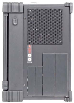


10 Chapter 1 Introduction / Specifications 2.0 Getting Started Front Open View Rear Open View Chassis Plans 6
11 Chapter 1 Introduction / Specifications Composite S Video Component MENU AUTO Chassis Plans 7
12 Chapter 2 - Operation Chapter 2 - Operation The MP1X20A is a well-designed compact portable computing machine that is both nimble as well as rugged. It will serve your needs for expansion as well as performance. An important aspect of the MP1X20A is the concept of standardization, which means all components that you can find off the shelf or of proprietary design will fit into the MP1X20A. If the peripheral is designed according to industry standard for interconnectivity then it will fit. With that in mind, we will layout and identify each of the component. In this section you can find each component of the MP1X20A with respect to its purpose and usage. Chassis Plans 8
13 Chapter 2 - Operation Drive Bays Right Side: 1x 5-1/4 Drive Bay 4x Removable 3-1/2 Drive Bays Left Side: 2x Removable 3-1/2 Drive Bays 1x Slim DVD 1x Slim Floppy Right Side View Left Side View Keyboard 108 key full-travel keyboard is integrated with the MP1X20A and attaches to the front. It may be used while connected or removed. This provides storage for the keyboard as well as protection for the LCD while in transit. Keyboard Cable The keyboard is provided with a coiled cord which connects to the bottom right of the front of the MP1X20A. Both keyboard and touch pad signals are carried by this cable. Other keyboards or pointing devices may be connected to the front panel USB ports. Chassis Plans 9
14 Chapter 2 - Operation LED Status Indicators The front panel provides two LED indicators. The green LED indicates power on. The red LED indicates hard disk drive access. Display Integrated TFT Active Matrix LCD provides UXGA 1.6M color display with resolution of 1600*1200. Brightness is 300nits with an 800:1 contrast ratio and 5mS response. The LCD is provided with a protective glass overlay with an anti-glare coating. A standard OSD allows fine tuning the display parameters. Controls are located on the left side of the chassis. Speaker Two speakers are provided to allow media audio play back without having to use external speakers. The speaker amplifier has a volume control on the left side for different environmental usage. Rubber Corner Bumpers The MP1X20 is provided with rubber bumpers for each corner to help protect the system from the bumps and hits expected for a portable device such as this. Power Switch The power switch to turn on the computer is located on the right side of the front panel. This is a standard momentary push button connected to the motherboard to take advantage of the ATX power control standards. Fans Two 120mm and two 80mm fans, located inside & rear side of the chassis, provide sufficient cooling for virtually any system configuration and environment. Other fan options are available for more flow or quieter operation. Optional fan controls and alarms are available. Filters Filters located on both sides of the MP1X20A help block out dust and dirt from entering the system. Expansion Slots Seven slots for the add-in cards are all externally accessible on the left side of the system. Handle A large handle is provided on top for convenient transportation of the system with comfort and ease. Keyboard Release Buttons These buttons, located on each side, when pushed will release the locking mechanism to detach the keyboard from the main MP1X20A chassis. Additional VGA Input Ports There are three different VGA ports which allow various VGA input. These are mounted on the left side. Chassis Plans 10


15 Chapter 2 - Operation 2.1 Keyboard and Touch pad How to release the Keyboard There are two release buttons located on the top-left and top-right of the chassis. When pushed, the keyboard is disengage from the MP1X20A and will swing down. There are also two spring pins located at the bottom of the keyboard that are inserted into the MP1X20A. Pressing these inward will release the keyboard entirely from the MP1X20A. The keyboard can be used while attached to the MP1X20A or when fully released, whatever is most comfortable for use. Lift Up How to close the keyboard Closing the keyboard back onto the MP1X20A follows the same procedure as opening, in a reverse manner. It is noted that the keyboard cable should be put back into its pocket. Make sure the two locking pins are properly secured before swinging the keyboard up to a closed position. The system should be transported only with the keyboard attached and closed so as to protect the LCD from damage. Lift Up Connecting the Keyboard The coiled keyboard cable, with an RJ45 connector, is located at the top of the keyboard in a pocket. The RJ45 should be plugged into the mating connector on the MP1X20A (at the lower right hand corner) to be operational. This will connect both the keyboard and touchpad. This RJ45 connection is not an Ethernet network connection and should not be plugged into one of those ports. Likewise, the RJ45 connection on the front of the MP1X20A is not a network connection even though a network cable will physically fit. Chassis Plans 11

 drivers must be installed for the operating system to recognize and take full")
16 Chapter 2 - Operation Touchpad operation The TouchPad surface can be used to move the cursor in the GUI environment by placing and moving your finger. The two buttons located below the touch pad act as same as the mouse left/right button. Or you may wish to tap on the touch pad to indicate a left click. Note the proper pointing device (TouchPad) drivers must be installed for the operating system to recognize and take full advantage of the features of the TouchPad. Chassis Plans 12
17 Chapter 2 - Operation 2.2 Right Side Panel There are four 3.5 removable drive trays and one regular 5.25 bay on the right side. The right side also provides the volume controls for the speaker. 2.3 Power Switch and AC Plug The power receptacle is located on the rear panel of the machine near the left side. A standard three-prong power plug is provided. Make sure the power switch on the power supply, if provided, is in the ON position before closing the rear panel. Power supplies are typically auto-selecting and will operate between 90 to 264VAC and 46-64Hz for universal world-wide power. The power switch on the front panel is a typical momentary switch connected to the motherboard to take advantage of the motherboard power control functionality. AC Input Chassis Plans 13
18 Chapter 2 - Operation 2.5 Connecting an External Monitor An external monitor or projector can be hooked up via the side panel VGA (15pin) port while the system is off. The Display/Projector will provide the cable to be inserted into this port. When connected, the display should appear if the machine is powered on. The signal is standard with the internal viewing resolution and the default setting is simultaneous display on both MP1X20A s LCD and CRT. To change the output mode (Simultaneous/LCD only/crt only), please refer to your VGA setting. 2.6 Audio The system audio does not require the user to install a sound card but, instead, uses the motherboard on-board audio. The built-in internal amplified speakers provide a phono stereo plug that will fit into the output port of the motherboard. Motherboard Audio Area Chassis Plans 14

19 Chapter 2 - Operation 2.7 Speaker Volume Adjustment There are two volume adjustments (Increase/Decrease) on the right side panel. 2.8 Slim Size CD-ROM & FDD Drive Bays The left side, bottom, provides for mounting a slim DVD and slim Floppy drive. Chassis Plans 15

 of Composite,")
20 Chapter 2 - Operation 2.9 Bottom Feet The bottom of the MP1X20A provides two feet that can be lowered to tilt the unit back. This makes for easier use of the LCD VGA & OSD The left side provides auxiliary video inputs (depending on your model) of Composite, S-Video or Component. The left side also provides the OSD controls for the LCD controller. Aux Video Inputs OSD Controls Chassis Plans 16

21 Chapter 2 - Operation 2.11 Front Panel USB Ports There are two USB ports on the front panel. These are connected to the motherboard internally and can be used for devices such as thumb drives, external hard drives, alternative keyboards or pointing devices such as track balls or joy sticks. Front Panel USB Ports 2.12 Cooling Fans The system is provided with two cooling fans, mounted on the right side and rear of the chassis. These are in addition to the fan in the power supply. The grills for these fans should be kept clean to allow the cooling air to escape the system. There are two additional 80mm fans near the motherboard slot area and adjacent to the power supply on the rear panel. Cooling Fan Cooling Fan Chassis Plans 17
22 Chapter 3 Internal Access Chapter 2 Internal Access WARNING Be sure the power cable is not connected to the system before proceeding. Even with the power turned off, the power supply will be supplying standby voltages to the motherboard and installing components to an energized motherboard may damage the motherboard, components or both. WARNING Components inside the system are subject to static discharge damage. Follow the proper grounding recommendations as outlined on page iii before handling installed components. Note: The following sections refer to your motherboard installation instructions. 3.1 Open back cover Unscrew Unscrew Unscrew Unscrew Chassis Plans 18

23 Chapter 3 Internal Access 3.2 Remove Card Stabilizer Bars Unscrew x2 Unscrew x2 Unscrew x2 Unscrew x2 Chassis Plans 19
24 Chapter 3 Internal Access 3.3 Remove the Side Vertical HDD Bays Unscrew x2 Unscrew x2 3.4 Install System Board with CPU and RAM Configure your motherboard per the manufacturer s instructions. Be careful to handle the motherboard per accepted anti-static practice to prevent damage. Do not handle the motherboard by the processor heat sinks as that can damage the processors and sockets. Also be careful to assure that all installed motherboard supports standoffs line up with a mounting hole and do not contact any motherboard traces. Chassis Plans 20

25 Chapter 3 Internal Access 3.5 Connect Keyboard and TouchPad Cables Connect the Keyboard and Touchpad cables to the appropriate connectors on the motherboard I/O area. Keyboard & Touchpad Connections 3.6 Connect Power, LED, and Speaker Wires Motherboard Control Connections Please refer to your System Board Manual for the actual location and pin-outs for the various chassis control connections for the Power Switch, LEDs, and Audio Output. Chassis Plans 21

26 Chapter 3 Internal Access 3.7 Accessing the Removable Hard Drives Loosen the drive retention screw. Drive Retention Screws Pull out the door cover. This unlocks the drive from the chassis. Pull out the drive tray. Mount the drive in the tray using the screws provided with the drive. Reinstall in reverse order. Chassis Plans 22

27 Chapter 3 Internal Access 3.8 Accessing the 5.25 Drive 2x Screw 2x Screw Chassis Plans 23
 from the side cover. 2x Screws 2mm 2x Screws 3mm Last, remove the philips head screw as shown.")
28 Chapter 3 Internal Access 3.9 Accessing the Slim DVD & FDD Remove the 4 screws from the bottom as shown. 4x 4x Screws Remove the 2 allen head screws (2mm) from the cover as shown. Then remove the 2 allen head screws (3mm) from the side cover. 2x Screws 2mm 2x Screws 3mm Last, remove the philips head screw as shown. This will allow the drive cage for the slim drives to be removed. Reinstall in reverse order. 1x Screw Chassis Plans 24
29 Chapter 4 - Maintenance Chapter 4 - Maintenance While the MP1X20A system is ruggedly designed and constructed, it is still a sensitive computing device and should be treated accordingly. Do not subject it to abuse such as dropping it or letting it bounce around in the back of a vehicle. It does not need to be babied but, on the other hand, it does need to be carefully handled to assure reliable operation. It is a fairly large, unwieldy, and heavy device. 4.1 Handling of the system: You should always make sure the keyboard assembly is properly latched onto the MP1X20A before transporting it. This will ensure you do not lose the keyboard as well as it will protect the LCD screen. You may transport the system in its carrying case, or you can carry the MP1X20A by its handle located on top of the machine. The handle is attached securely to the strongest part of the machine and distributes the load of the MP1X20A evenly to allow easy carriage and comfortable balance. 4.2 Handling of Cables: All cables should be treated with care. Do not over extend any cable as this could result in breakage internally in the cable. It is essential that cables with its plug be handled without force on the connector. 4.3 Handling of the LCD: Do not use any abrasive material that might scratch the LCD screen. Do not apply any pressure to the surface of the LCD screen either with objects or fingers; this will ensure that the screens do not suffer from internal damage or cracks. 4.4 AC Power: Always make sure the power cord is in good condition before using with the MP1X20A. Make sure your power source is reliable and of proper standard. The MP1X20A power supply is capable of handling typical V and 50-60Hz inputs. Do not use the MP1X20A on an already overloaded circuit. PS/2 style power supplies do not offer much in the way of surge protection or lightening overload protection. It is always a good idea with any computer to provide a surge protector in line with the AC power to protect the system. The MP1X20A does not provide internal battery backup. 4.5 Handling of the Keyboard / Touchpad: The keyboard is not sealed. Do not subject the keyboard to spilled liquids or small debris (which might jam the keys). The touch pad surface should be kept dry and clean for proper usage. 4.6 Cleaning the LCDs: 1. Do not use a cleaner that contains alcohol. 2. Do not use cloths that could be abrasive to the surface of the LCD. 3. Always gently wipe the LCD surface when cleaning. 4.7 Cleaning the Keyboard / Touchpad: 1. Do not spill any liquid on to the keyboard. 2. Do not drop particle into the spacing between keys. 3. Using a compressed air cleaner, you can remove the dust build-up within. 4.8 Cleaning the Fan Filter: 1. Remove the filter from its housing. 2. Use a compressed air cleaner to blow off the dust from the filter. 3. If necessary, you can wash the filter material, but do remember to dry it first. Chassis Plans 25
30 Chapter 5 - Troubleshooting Chapter 5 - Troubleshooting The following are quick problem solving tips. Please contact Chassis Plans Customer Service Department at Service@chassisplans.com or by calling for technical assistance. Note: Unplug the power cord before servicing internal components to prevent damage. The power supply will provide standby power to the motherboard even when Off. Removing or inserting a plug-in card with power applied will damage the card, motherboard, or both. Hint: Often the best troubleshooting technique is to simple push on the memory modules, installed cards, and connected cables to make sure they are all seated. The second best technique is to either test a suspect component in a known working system or use substitute a known good component to see if the problem goes away. However, it has been seen that new components are dead out of the box. Thus, you think the problem is not with that component when, in actuality, you have two dead boards, drives, etc. 5.1 Installation problem: 1. Normally, a problem with a failed start up is due to a card installation problem. 2. Double check all the peripheral cards or items you have added to the MP1X20A. 3. Are all the items seated properly? 4. Are all the cables connected back to the original or correct position? 5. Are the items you have added compatible? 6. Check for 1 thru 5 and then re-power up the computer. 7. Remove all items that were added and re-try system power up. 8. If the system starts now, try inserting 1 new item in at a time and try powering up. 9. Repeat this step until you get the desired result. 5.2 BIOS Beep Code: The BIOS beep code indicates error in system initialization. The BIOS of the system board will associate with video and memory error. Please check your video card is properly seated and your memory is installed properly. Check the manual for the motherboard for the BIOS codes. 5.3 System Fails to power up: 1. Check your power connection first. 2. Check the main power switch is in the ON positions (I) (if power supply so equipped). 3. Press the power button located in front of the machine. 4. If the fan in the power supply starts but the system does not appear to power up, then it would most likely be a motherboard issue. 5. Check to be sure the motherboard is not shorting to any standoffs. 5.4 No internal display (LCD): 1. Check that all the proper power up procedures have been performed. 2. Connect an external CRT to the VGA port to check if video is present. 3. If video is present on external CRT, check the internal LCD cable connection. 4. Check your VGA setting using an external display to make sure LCD video is enabled. 5. If there is no video on external, check your system to make sure everything is seated properly. 6. If everything is seated properly and still no video, call us for further assistance. Chassis Plans 26
31 Chapter 5 - Troubleshooting 5.5 External CRT no display: 1. Check to see if you have internal LCD video. 2. Check if your CRT is functioning properly (connect to another computer). 3. Check your VGA setting to make sure external video is enabled. 5.6 Keyboard fails: Note: Typically, if the keyboard fails due to a faulty connection, the TouchPad will also not work. If one or the other device works, then it is a failed keyboard issue or a driver issue. 1. Make sure the keyboard plug is inserted completely into the front port. 2. Assure the internal keyboard connection is secure. 3. Make sure you do not have another keyboard connected to the motherboard I/O PS/2 port. 4. Test a keyboard in the motherboard USB port. 5. Try another keyboard to isolate the problem to the keyboard or system. 5.7 Touchpad fails: 1. Make sure the keyboard plug is inserted completely into the port. 2. If you have an external PS/2 mouse hook up on the side I/O PS/2 port, the touch pad may not function simultaneously. 3. If your operating system requires and does not load the mouse driver automatically, make sure you have the proper mouse driver loaded. 4. Try another pointing device to isolate the problem to TouchPad versus system. 5.8 DVD-ROM fails: 1. Make sure the CD/DVD is readable. 2. If DVD-ROM fails to be recognized during POST, check internal cable fit. 5.9 Hard Drive fails: 1. Hard drives are the least reliable component in a system. 2. If Hard Drives fail to be recognized during POST, check internal cable fit. 3. Remove each drive canister and check the connectors for damage. 4. Remove and reinstall the canisters to assure they are properly seated and locked in place. Chassis Plans 27
32 Chapter 5 - Troubleshooting Chapter 6 Packing List Package Contents Description Qty 1 User s Manual User s Reference Guide 1 2 ESD Bag ESD Bag for additional packaging 1 3 Power Cord Power Cord 1 4 Screw Pack Screw Pack (stabilizer) 1 5 Stabilizer Supports Pack 6 Hardware Pack (system) Additional clip for card holder to secure add-in card 1 Additional cabling for internal interconnect 1 7 MP1X20A System Main system unit chassis 1 8 Carrying Bag Tow bag with wheels 1 Chassis Plans 28
MP1X17A Rugged Portable Computer TECHNICAL REFERENCE. Revision A
 MP1X17A Rugged Portable Computer TECHNICAL REFERENCE Revision A 1 WARRANTY The following is an abbreviated version of Chassis Plans warranty policy for portable products. For a complete warranty statement,
Rackmount Keyboard Installation Instructions. Revision A A-0000
 Rackmount Keyboard Installation Instructions Revision A 22000200A-0000 WARRANTY The following is an abbreviated version of warranty policy for keyboard products. For a complete warranty statement, contact
ARP 945 User Reference Manual
 ARP 945 User Reference Manual Specifications Model No ARP945 ARP945-B CPU Intel Core 2 Duo T7500 (2.2GHz) Processors (Option: T9400, 2.53GHz) Slots Intel Gm45 Chipset + ICH9M Slot 3x PCI-E (x8) full-size
AZTEC-ATX4 User Reference Manual
 AZTEC-ATX4 User Reference Manual Specifications Model No AZTEC-ATX4 AZTEC-ATX4 Motherboard Support ATX M/B Support SBC with Backplane Slots Offer 7 expansion slots Offer 10 expansion slots Drive bay 1x
ARP 640-P User Reference Manual
 ARP 640-P User Reference Manual Specifications Model No ARP640-P Motherboard Support Micro ATX Motherboard Slots Offer 4 full length expansion slots (338.5mm) Drive bay Support 2x 5.25, slim DVD-RW, 1x
ARP992/ ARP992-B User Reference Manual
 ARP992/ ARP992-B User Reference Manual Specifications Model No ARP992 ARP992-B CPU Intel Core i5-7440eq, 2.90GHz Processors Option: Intel Core i7-7820eq, 3.0 GHz Chipset Intel 7th Gen. Core i5 /i7 processors
ARP 690 User Reference Manual
 ARP 690 User Reference Manual Specifications Model No Motherboard Slots Display Drive bay VGA KB/MS Power Supply Construction Speaker Dimension Weight Carrying Case ARP690 Support ATX Motherboard Offer
ARP 970 User Reference Manual
 ARP 970 User Reference Manual Specifications Model No ARP970 ARP970-B CPU Intel Core i5-2510e, 3M Cache, 2.50GHz Processors (Option: Intel Core i7-2710qe, 6M Cache, 2.10 GHz) Chipset Intel QM77 Express
ARP 670 User Reference Manual
 ARP 670 User Reference Manual Specifications Model No ARP670 ARP670-S Motherboard Support ATX M/B Support SBC with Backplane Slots Offer 7 expansion slots Offer 10 expansion slots Drive bay 1x 5.25, 1x
ARL 945/ ARL945-B User Reference Manual
 ARL 945/ ARL945-B User Reference Manual Specifications Model No ARL945 ARL945-B CPU Intel Core 2 Duo T7500, 2.2GHz Processors (Option: Intel Core 2 Duo T9400, 2.53 GHz) Chipset Intel Gm45 Chipset + ICH9M
ARL992/ ARL992-B User Reference Manual
 ARL992/ ARL992-B User Reference Manual Specifications Model No ARL992 ARL992-B CPU Intel Core i5-7440eq, 2.90GHz Processors Option: Intel Core i7-7820eq, 3.0 GHz Chipset Intel 7th Gen. Core i5 /i7 processors
ARX 308 User Reference Manual
 ARX 308 User Reference Manual Specifications Model No Backplane Accessible Slots Display Drive bay KB/MS Power Supply Construction Dimension Weight Carrying Case ARX308 3U-size, 8-slot PXI backplane Compliant
ARL 970/ ARL970-B User Reference Manual
 ARL 970/ ARL970-B User Reference Manual Specifications Model No ARL970 ARL970-B CPU Intel Core i5-2510e, 3M Cache, 2.50GHz Processors (Option: Intel Core i7-2710qe, 6M Cache, 2.10 GHz) Chipset Intel QM77
Gateway Profile 4 service guide
 Gateway Profile 4 service guide Customizing Troubleshooting Contents Replacing Components in Your Gateway Profile 4.................. 1 About this guide.....................................................
WL-21701/21708/21716 User Reference Manual. Revision 1.3 (080717)
") WL-21701/21708/21716 User Reference Manual Revision 1.3 (080717) LCD Keyboard Drawer Specification for WL-21701/21708/21716 Chassis External Chassis Industrial Metal Frame Display LCD 17, 19" Diagonal
WL-21701/21708/21716 User Reference Manual Revision 1.3 (080717) LCD Keyboard Drawer Specification for WL-21701/21708/21716 Chassis External Chassis Industrial Metal Frame Display LCD 17, 19" Diagonal
Table of Contents. Overview...2. Features...2. Packing List...3. Assembly...5. Installation...8. Front Panel...9
 Table of Contents INTRODUCTION...1 SERVERLINK LCD CONSOLE Overview...2 Features...2 Packing List...3 Assembly...5 Installation...8 Front Panel...9 Replaceable Keyboard and Touch Pad... 10 LCD Specification...
SATA II HDD Canister KISS DA 435 Quick Reference Guide
 SATA II HDD Canister KISS DA 435 Quick Reference Guide If it s embedded, it s Kontron 1. Table of Contents SATA II HDD Canister KISS DA 435 1. Table of Contents 1. Table of Contents... 1 2. Important Information...
Dell Inspiron XPS and Inspiron 9100 Service Manual
 Dell Inspiron XPS and Inspiron 9100 Service Manual Dell Inspiron XPS and Inspiron 9100 Service Manual Before You Begin Memory Module, Mini PCI Card, and Devices System Components Subwoofer Bluetooth Card
After completing this chapter, you will meet these objectives:
 3.0 Introduction Assembling computers is a large part of a technician's job. As a technician, you will need to work in a logical, methodical manner when working with computer components. As with any learned
User Manual AIMB-C200. Economical Embedded Chassis for Mini-ITX Motherboard
 User Manual AIMB-C200 Economical Embedded Chassis for Mini-ITX Motherboard Copyright The documentation and the software included with this product are copyrighted 2010 by Advantech Co., Ltd. All rights
MIC-3001/8. 3U/4U CompactPCI. Enclosure for Rackmounting
 MIC-3001/8 3U/4U CompactPCI Enclosure for Rackmounting Copyright Notice This document is copyrighted, 1999. All rights are reserved. The original manufacturer reserves the right to make improvements to
Thank you for purchasing this Factory Service Manual CD/DVD from servicemanuals4u.com.
 Thank you for purchasing this Factory Service Manual CD/DVD from servicemanuals4u.com. Please check out our ebay auctions for more great deals on Factory Service Manuals: servicemanuals4u Dell Inspiron
SMK 920/980/990 (P) User Reference Manual
 User Reference Manual") SMK 920/980/990 (P) User Reference Manual Revision 1.8 LCD Keyboard Drawer Specification for SMK 920/980/990 (P) P/N: 82002-01054 1 Chassis External Chassis Industrial Metal Frame Display LCD 17, 19" Diagonal
SMK 920/980/990 (P) User Reference Manual Revision 1.8 LCD Keyboard Drawer Specification for SMK 920/980/990 (P) P/N: 82002-01054 1 Chassis External Chassis Industrial Metal Frame Display LCD 17, 19" Diagonal
MIC-3002A Series. 3U 6-slot CompactPCI Enclosures with Rear I/O and 6" LCD. User Manual
 MIC-3002A Series 3U 6-slot CompactPCI Enclosures with Rear I/O and 6" LCD User Manual Copyright The documentation and the software included with this product are copyrighted 2005 by Advantech Co., Ltd.
TRC4011 4U RACKMOUNT COMPUTER TVC U Rackmount. Video Display Wall Controller
 TRC4011 4U RACKMOUNT COMPUTER & TVC4403 4U Rackmount Video Display Wall Controller No. TRC4011-xxx / TVC4403-xxx Revision C INSTALLATION GUIDE Publication No. 8404011-09142 WARRANTY The following is an
MIC-3001/8. 3U/4U CompactPCI Enclosure for Rack Mounting. User Manual
 MIC-3001/8 3U/4U CompactPCI Enclosure for Rack Mounting User Manual Copyright The documentation and the software included with this product are copyrighted 2004 by Advantech Co., Ltd. All rights are reserved.
MIC Advantech CompactPCI. Modular Industrial Computer. 10U high 8-slot enclosure with CT bus and rear I/O for CompactPCI backplane
 MIC-3081 10U high 8-slot enclosure with CT bus and rear I/O for CompactPCI backplane Advantech CompactPCI Modular Industrial Computer Copyright Notice This document is copyrighted, 2003. All rights are
User s Manual 19 High Speed Panel PCwith one PCI slot, 180W ATX P/S Version 1.0 September 2008
 2907770 User s Manual 19 High Speed Panel PCwith one PCI slot, 180W ATX P/S Version 1.0 September 2008 Copyrights This document is copyrighted and all rights are reserved. It does not allow any non authorization
HOME THEATER PC CHASSIS
 HOME THEATER PC CHASSIS Model: HTPC 280 BAV4 & SAV4 Color: Black & Silver Quick Installation Guide (U.S. & Canada Only) Version 1.0 DISCLAIMER No warranty or representation, either expressed or implied,
FCC COMPLICANCE STATEMENT
 FCC COMPLICANCE STATEMENT For Users in the USA This equipment has been tested and found to comply with the limits for a Class B digital device, pursuant to Part 15 of FCC Rules. These rules are designed
Folding Rackmount Console
 Folding Rackmount Console 15 Folding LCD Rackmount Console 17 Folding LCD Rackmount Console 19 Folding LCD Rackmount Console RACKCONS1501 RACKCONS1701 RACKCONS1901 Instruction Manual Actual product may
WEASEL N/B MAINTENANCE
 2. System Assembly & Disassembly 2.1 System View 2.1.1 Front View ❶ Microphone Connector ❷ Audio Input Connector ❸ Audio Output Connector ❹ Top Cover Latch ❹ ❶ ❸ ❷ 2.1.2 Left-Side View ❶ VGA Port ❷ S-Video
DKP-115/117/119-Fe Single Rail Console with Modular KVM Switch User Manual
 DKP-115/117/119-Fe Single Rail Console with Modular KVM Switch User Manual Rev 1.0 DKP-115/117/119-Fe User Manual I Packing List The complete DKP-115 / 117 / 119-Fe single rail console with modular KVM
Computer Assembly Step by Step DRAFT
 9781587132636_ch03.qxp 8/20/10 1:37 PM Page 79 CHAPTER 3 Computer Assembly Step by Step Objectives Upon completion of this chapter, you should be able to answer the following questions: How do I open the
3-4 SAS/SATA II HDD Canister Entry version USER S MANUAL XC-34D1-SA10-0-R. Document number: MAN A
 3-4 SAS/SATA II HDD Canister Entry version XC-34D1-SA10-0-R USER S MANUAL Document number: MAN-00077-A ii Preface Important Information Warranty Our product is warranted against defects in materials and
8806 Series. 15 Multi-functional Touch Panel PC. Quick Reference Guide
 8806 Series 15 Multi-functional Touch Panel PC Quick Reference Guide 1st Ed 10 July, 2009 8806 Contents 1. Getting Started...3 1.1 Safety Precautions...3 1.2 Packing List...3 1.3 System Specifications...4
LevelOne KVM User Manual. 17 Modularized KVM Console V
 LevelOne KVM-0217 17 Modularized KVM Console User Manual V1.0.0-0708 SAFETY INSTRUCTIONS 1. Please read these safety instructions carefully. 2. Please keep this User Manual for later reference. 3. Please
BHK117Ue/BHK119Ue User Reference Manual l-tech COMPANY
 BHK117Ue/BHK119Ue User Reference Manual l-tech COMPANY i-tech Company LLC TOLL FREE: (888) 483-2418 EMAIL: info@itechlcd.com WEB: www.itechlcd.com LCD Keyboard Drawer Specification for BHK117Ue/BHK119L)e
G-MAX TM. ATX Series User s Manual
 Copyright Notice Copyright 2001 Gigabyte Technology. All Rights Reserved. No part of this documentation, including but not limited to the products and software described in it, may be reproduced, transmitted,
TravelMate 6493 Series Disassembly Instruction
 TravelMate 6493 Series Disassembly Instruction please refer to http://csd.acer.com.tw PRINTED IN TAIWAN Chapter 3 Machine Disassembly and Replacement This chapter contains step-by-step procedures on how
imac Intel 21.5" EMC 2389 Stand Replacement
 imac Intel 21.5" EMC 2389 Stand Replacement Replace a broken or cosmetically unappealing stand on the imac 2389 21.5 Written By: Aaron Cooke ifixit CC BY-NC-SA www.ifixit.com Page 1 of 30 INTRODUCTION
P160 User s Manual Manuel de l utilisateur Anwenderhandbuch Manuale per l operatore Manual del usuario
 P10 User s Manual Manuel de l utilisateur Anwenderhandbuch Manuale per l operatore Manual del usuario At Antec, we continually refine and improve our products to ensure the highest quality. So it's possible
ipad Charge & Sync Cart Model MCC2 ipad Cart 430-MCC2-User Manual-010 Is a Registered Trademark of Apple Inc. ipad
 ipad Charge & Sync Cart Model MCC2 ipad Cart ipad Is a Registered Trademark of Apple Inc. 430-MCC2-User Manual-010 1. ipad Cart Specifications MCC2 Mobile Charge & Sync Cart Extra Drawer Reserved space
Written By: Walter Galan
 imac Intel 21.5" EMC 2428 CPU Replacement Replace the CPU in your imac Intel 21.5" EMC 2428. Written By: Walter Galan ifixit CC BY-NC-SA www.ifixit.com Page 1 of 33 INTRODUCTION Use this guide to upgrade
Upgrading and Servicing Guide
 Upgrading and Servicing Guide Copyright Information The only warranties for Hewlett-Packard products and services are set forth in the express statements accompanying such products and services. Nothing
RUGGED MILITARY GRADE
 R4U-20A RUGGED MILITARY GRADE COTS Plus 4U ENCLOSURE Optimized for High Shock / Vibration Environments C6CHASSIS SYSTEMS ENGINEERED TO PERFORM The R4U-20A is designed to survive! Aircraft grade aluminum
TRC2002 2U RACKMOUNT COMPUTER
 TRC2002 2U RACKMOUNT COMPUTER No. TRC2002-xx Revision A INSTALLATION GUIDE Publication No. 8402002-11110 WARRANTY The following is an abbreviated version of Trenton Systems s warranty policy for rackmount
Serial ATA Hot Swap Drive Cage Upgrade Kit for: Intel Server Chassis SC5200 Intel Server Chassis SC5250-E
 Serial ATA Hot Swap Drive Cage Upgrade Kit for: Intel Server Chassis SC5200 Intel Server Chassis SC5250-E A Guide for Technically Qualified Assemblers of Intel Identified Subassemblies/Products Order Number:
SH-5921 PANEL PC TFT LCD (Ver 1.0)
") SH-5921 PANEL PC 15.0 TFT LCD (Ver 1.0) Copyright Notice Copyright 2003 by Wingtop Co., LTD. All Rights Reserved. The information in this document is subject to change without prior notice in order to
SH-5921 PANEL PC 15.0 TFT LCD (Ver 1.0) Copyright Notice Copyright 2003 by Wingtop Co., LTD. All Rights Reserved. The information in this document is subject to change without prior notice in order to
User Manual LKS-CD17SR 17 LCD Single Rail Console Drawer with Modular KVM Switch
 User Manual LKS-CD17SR 17 LCD Single Rail Console Drawer with Modular KVM Switch LKS-CD19SR 19 LCD Single Rail Console Drawer with Modular KVM Switch Rev 2.0 Packing List ServerLink LKS-CD17SR / CD19SR
Table of Contents. Overview...3. Features...3. Packing List...4. Assembly...6. Installation...9. Front Panel...10
 Table of Contents INTRODUCTION...1 CONSOLE Overview...3 Features...3 Packing List...4 Assembly...6 Installation...9 Front Panel...10 Replaceable Keyboard and Touch Pad...11 LCD Specification...13 Please
MPP1700 User s Manual
 2011 Visionary Solutions, Inc. All rights reserved. Please visit the support section of our website at www.vsicam.com for manuals, other documentation, and software downloads. Visionary Solutions, Inc.
Upgrading and Servicing Guide
 Upgrading and Servicing Guide The only warranties for Hewlett-Packard products and services are set forth in the express statements accompanying such products and services. Nothing herein should be construed
FWA-6280A User Manual 1. FWA-6280A User Manual
 1 Copyright Notice This document is copyrighted, 2005. All rights are reserved. The original Manufacturer reserves the right to make improvements to the products described in this manual at any time without
Atlas Quiet Mini Server Case. User s Manual Manuel de l utilisateur Anwenderhandbuch Manuale per l operatore Manual del usuario
 Atlas Quiet Mini Server Case User s Manual Manuel de l utilisateur Anwenderhandbuch Manuale per l operatore Manual del usuario 1 At Antec, we continually refine and improve our products to ensure the highest
4.1 General. 4 Replacement Procedures
 4.1 General This chapter explains how to disassemble the computer and replace Field Replaceable Units (FRUs). It may not be necessary to remove all the FRUs in order to replace one. The chart below is
PMX09 DATA SHEET FEATURES A PORTABLE 9-SLOT 3U PXI EXPRESS CHASSIS WITH INTEGRATED DISPLAY AND KEYBOARD
 83-0039-000 14A DATA SHEET PMX09 PORTABLE 9-SLOT 3U PXI EXPRESS CHASSIS WITH INTEGRATED DISPLAY AND KEYBOARD FEATURES 9-slot PXI Express chassis with 1 system controller slot, 6 peripheral slots, 1 hybrid
Dell Inspiron N5110 Service Manual
 Dell Inspiron N5110 Service Manual Regulatory model: P17F Regulatory type: P17F001 Notes, Cautions, and Warnings NOTE: A NOTE indicates important information that helps you make better use of your computer.
USER MANUAL. User Manual 17 / 19 LCD. NVP117 / NVP119 1U LCD Console Drawer. Options : - AV / DVI-D / HDMI / Audio - Full Range KVM - DC power
 USER MANUAL 17 / 19 LCD NVP117 / NVP119 1U LCD Console Drawer Options : - AV / DVI-D / HDMI / Audio - Full Range KVM - DC power Contents < Part. 1 > NVP117 / NVP119 1.1 Package Content 1.2 Structure Diagram
Instrument Mainframe 7500
 Instrument Mainframe 7500 Instrument Mainframe 7500 is a high-quality portable enclosure Portable computer for use with CompuScope and CompuGen cards for CompuScope and CompuGen cards. Using an Instrument
Upgrading and Servicing Guide
 Upgrading and Servicing Guide Copyright Information The only warranties for Hewlett-Packard products and services are set forth in the express statements accompanying such products and services. Nothing
Installation Guide. Copyright 2005 MSI Computer Corp.
 Installation Guide Copyright 2005 MSI Computer Corp. Overview: 1013 is shipped out as a barebone. Some of the components are equipped while some are not. This installation guide provides you with the information
MPP200 User s Manual
 2011 Visionary Solutions, Inc. All rights reserved. Please visit the support section of our website at www.vsicam.com for manuals, other documentation, and software downloads. Visionary Solutions, Inc.
Home Theater PC Chassis
 Home Theater PC Chassis Model: HTPC 300 BA & SA Color: Black & Silver Quick Installation Guide (U.S. & Canada Only) Version 1.0 DISCLAIMER No warranty or representation, either expressed or implied, is
Vertiv Local Rack Access 18.5" LED LCD Console
 Vertiv Local Rack Access 18.5" LED LCD Console With Integrated Keyboard, Touchpad and Dual USB 2.0 Ports Installer/User Guide Technical Support Site If you encounter any installation or operational issues
2. Why is it important to remove loose jewelry before working inside a computer case?
 Chapter 2 Solutions Reviewing the Basics 1. When taking a computer apart, why is it important to not stack boards on top of each other? Answer: You could accidentally dislodge a chip. 2. Why is it important
(Hardware and case keys are provided inside the chassis storage compartment.)
") 1. Motherboard installation...1 2. Install 3½ and 5¼ drives...3 3. Install PCI components...4 4. Fan installation and setup...5 5. Temperature probe setup...6 6. Connect case leads to motherboard...7 7.
1. Motherboard installation...1 2. Install 3½ and 5¼ drives...3 3. Install PCI components...4 4. Fan installation and setup...5 5. Temperature probe setup...6 6. Connect case leads to motherboard...7 7.
Upgrading and Servicing Guide
 Upgrading and Servicing Guide The information in this document is subject to change without notice. Hewlett-Packard Company makes no warranty of any kind with regard to this material, including, but not
PANEL 6122-O/P 12.1 INDUSTRIAL TFT LCD MONITOR
 PANEL 6122-O/P 12.1 INDUSTRIAL TFT LCD MONITOR User s Manual Disclaimers The information in this manual has been carefully checked and is believed to be accurate. AXIOMTEK Co., Ltd. assumes no responsibility
Nexio. NEXIO Co.,Ltd. NIO150SA Desktop Touch Monitor. LCD Monitor User Guide.
 Nexio NEXIO Co.,Ltd. www.inexio.co.kr NIO150SA Desktop Touch Monitor VGA, DVI, Composite, S-video & Audio supported LCD Monitor User Guide Please see the following page for the latest enhancements. Revised
User Manual ARK-6610/6620. Compact Mini-ITX Chassis
 User Manual ARK-6610/6620 Compact Mini-ITX Chassis Copyright The documentation and the software included with this product are copyrighted 2007 by Advantech Co., Ltd. All rights are reserved. Advantech
Instruction Guide. Removable Drive Drawer With Shock Absorbers for 3.5 IDE Hard Drive DRW110ATA DRW110ATABK DRW113ATA DRW113ATABK
 REMOVABLE HARD DRIVE DRAWER Removable Drive Drawer With Shock Absorbers for 3.5 IDE Hard Drive DRW110ATA DRW110ATABK DRW113ATA DRW113ATABK Instruction Guide * Actual product may vary from photo *DRW110ATA
ipanel CONTROL TECHNOLOGY CORPORATION ipanel Installation Guide and Specifications ipanel Installation Guide
 ipanel CONTROL TECHNOLOGY CORPORATION ipanel Installation Guide and Specifications ipanel Installation Guide CONTROL TECHNOLOGY CORPORATION ipanel Installation Guide and Specifications 2003 Control Technology
Sunlight Readable Touch Monitor. Industrial Touch Monitor. Sunlight Readable Series. CS-100/M1000 Series
 Sunlight Readable Touch Monitor Industrial Touch Monitor Sunlight Readable Series Contents Preface Revision..... 03 Copyright Notice 03 Acknowledgement... 03 Disclaimer... 03 Declaration of Conformity.
Installing the Cisco ADE 2130 and 2140 Series Appliance Hardware Options
 CHAPTER 4 Installing the Cisco ADE 2130 and 2140 Series Appliance Hardware Options This chapter provides instructions for installing, replacing, and removing various hardware options in your Cisco ADE
Folding Rackmount Console
 RACKCONS2001 Instruction Manual Folding Rackmount Console 1U 20.1 Folding LCD Rackmount Console - USB and PS/2 FCC Compliance Statement This equipment has been tested and found to comply with the limits
LevelOne. KVM-0115/KVM / 17-inch LCD KVM Rack Console. User Manual. Version
 LevelOne KVM-0115/KVM-0117 15 / 17-inch LCD KVM Rack Console User Manual Version 1.0-1305 1 SAFETY INSTRUCTIONS 1. Please read these safety instructions carefully. 2. Please keep this User Manual for later
LVN5200A-R2, rev. 1, Hardware Installation Guide
 LVN5200A-R2 LVN5250A-R2 LVN5200A-R2, rev. 1, Hardware Installation Guide Customer Support Information Order toll-free in the U.S.: Call 877-877-BBOX (outside U.S. call 724-746-5500) FREE technical support
Unicorn 15 / 17 / 19 / 19W Single Rail Console with Modular KVM Switch User Manual
 Unicorn 15 / 17 / 19 / 19W Single Rail Console with Modular KVM Switch User Manual Rev 4.0 Packing List Unicorn series User Manual The complete Unicorn 15 / 17 / 19 single rail console with modular KVM
VTPC190V / VS / VDC / VSDC
 Solutions for Demanding Applications VARTECH S Y S T E M S I N C. 19.0 Enclosed VESA Mount PC Model VTPC190V / VS / VDC / VSDC User s Guide Read these instructions completely before attempting to operate
User Manual LKS-CD17DR LKS-CD19DR. 17 LCD Dual Rail Console Drawer with Modular KVM Switch. 19 LCD Dual Rail Console Drawer with Modular KVM Switch
 User Manual LKS-CD17DR 17 LCD Dual Rail Console Drawer with Modular KVM Switch LKS-CD19DR 19 LCD Dual Rail Console Drawer with Modular KVM Switch Rev 2.0 Packing List The complete LKS-CD17DR / CD19DR dual
To connect the AC adapter:
 Replacing the AC Adapter Replacing the AC Adapter 3 Plug the power cord into a wall outlet. The power indicator turns on. To connect the AC adapter: Connect the power cord to the AC adapter. Power indicator
Table of Contents Quick Install Guide page Introduction Safety Rack System Precautions ESD Precautions...
 Table of Contents Quick Install Guide page 1 EN English Table of Contents 1. Introduction... 2 1.1 Safety... 2 1.2 Rack System Precautions... 2-3 1.3 ESD Precautions... 3... 3 1... 3 2 Fitting PSU s...
User Manual. Rack Mount Display Monitor RMP-161-F17A. 6U 17.3 inch Rack Mount Display Monitor. Options : - AV, S-video input - Touchscreen
 User Manual Rack Mount Display Monitor RMP-161-F17A 6U 17.3 inch Rack Mount Display Monitor Options : - AV, S-video input - Touchscreen Contents < Part. 1 > RMP-161-F17A 1.1 Package Content 1.2 Structure
Tiger Box Expansion Chassis Assembly Guide
 Tiger Box Expansion Chassis Assembly Guide Product Overview................................. 3 Tiger Box Expansion Chassis Features............... 3 Package Content............................. 4 Hardware
TABLE OF CONTENTS SECTION 1 TABLETOP CONFIGURATION SECTION 2 TABLETOP CONFIGURATION ACCESSORIES SECTION 3 SLIDE CONFIGURATION
 S6 USER S MANUAL TABLE OF CONTENTS SECTION 1 TABLETOP CONFIGURATION SECTION 2 TABLETOP CONFIGURATION ACCESSORIES SECTION 3 SLIDE CONFIGURATION SECTION 4 SLIDE CONFIGURATION ACCESSORIES SECTION 5 RACK MOUNT
DEFINE XL COMPUTER DEFINE XL COMPUTER CASE CASE
 DEFINE XL COMPUTER DEFINE XL COMPUTER CASE CASE USER S MANUAL 1.1 Thank you and congratulations on your purchase of your new Fractal Design Define XL ATX Computer Case! Before using the case, please take
Instructions for SVC-KIT-0020
 Kaleidescape, Inc. July 22, 2010 Instructions for SVC-KIT-0020 Title Time to complete 1U Server Power Supply Replacement 1 hour Procedure to complete Locate Parts and Tools Service Kit Parts Power supply
120Ra-1 Pentium III Processor Installation Insert
 120Ra-1 Pentium III Processor Installation Insert PN: 455-01614-000 Proprietary Notice and Liability Disclaimer The information disclosed in this document, including all designs and related materials,
Removing and Replacing Parts
 Removing and Replacing Parts Preparing to Work Inside the Computer Recommended Tools Screw Identification System Components Hard Drive Fixed Optical Drive Media Bay Devices Memory Modules Mini PCI Card
Hardware Replacement Guide Types 8099, 8116, 8155, 8156 Types 8157, 8158, 8159, 8160 Types 8215, 9210, 9211
 Hardware Replacement Guide Types 8099, 8116, 8155, 8156 Types 8157, 8158, 8159, 8160 Types 8215, 9210, 9211 Hardware Replacement Guide Types 8099, 8116, 8155, 8156 Types 8157, 8158, 8159, 8160 Types 8215,
PIM-Mini Pulsed Current Source Operation Manual
 PIM-Mini Pulsed Current Source Operation Manual Directed Energy, Inc. 1609 Oakridge Dr., Suite 100, Fort Collins, CO 80525 (970) 493-1901 sales@ixyscolorado.com www.ixyscolorado.com Manual Document 7650-0007
Allworx 24x Service and Troubleshooting Guide
 Allworx 24x Service and Troubleshooting Guide -PAGE INTENTIALLY LEFT BLANK- Table of Contents 1 Safety Instructions...1 1.1 Electrical...1 1.2 Electrostatic Discharge...1 2 Chassis Views...2 3 Exterior
OPERATIONS MANUAL PCM-DOC
 OPERATIONS MANUAL PCM-DOC NOTE: This manual has been designed and created for use as part of the WinSystems Technical Manuals CD and/or the WinSystems website. If this manual or any portion of the manual
PSA200 User s Manual
 2011 Visionary Solutions, Inc. All rights reserved. Please visit the support section of our website at www.vsicam.com for manuals, other documentation, and software downloads. Visionary Solutions, Inc.
HP ProLiant SL160z G6 Server
 HP ProLiant SL160z G6 Server Installation Instructions Part Number 571291-004 Item Description 7 UID LED/SW 8 PCI Slot 9 Health LED 10 Power Button Rear Panel Components Figure 2 Rear panel components
CyberView User Manual
 CyberView User Manual RKP215-801 RKP217-801 RKP215-1601 RKP217-1601 2U Rackmount LCD monitor Keyboard drawer with KVM switch Version 2.0 20 March 2004 Table of Contents 1.0 General... 3 1.1 Unit Introduction...
PANEL6100 & PANEL6100L INDUSTRIAL TFT LCD MONITOR User s Manual
 PANEL6100 & PANEL6100L 10.4 INDUSTRIAL TFT LCD MONITOR User s Manual Disclaimers The information in this manual has been carefully checked and is believed to be accurate. Axiomtek Co., Ltd. assumes no
Reference Manual EPM-PS1. PC/104-Plus Power Supply Module DOC. REV. 4/29/2009
 Reference Manual DOC. REV. 4/29/2009 EPM-PS1 PC/104-Plus Power Supply Module WWW.VERSALOGIC.COM 12100 SW Tualatin Road Tualatin, OR 97062-7341 (503) 747-2261 Fax (971) 224-4708 Contents Copyright 2013
HP ProLiant DL165 G7 Server
 HP ProLiant DL165 G7 Server Installation Instructions Part Number 601464-003 Identifying server components Front panel components Figure 1 Front Panel Components / 4 3.5 LFF HDD Item Description 1 Thumbscrews