An Automatic Posture Planning Software of Arc Robot Based on SolidWorks API
|
|
|
- Phyllis Parks
- 5 years ago
- Views:
Transcription
1 Abstract An Automatic Posture Planning Software of Arc Robot Based on SolidWorks API Junfeng Li, Liangyu Li, Zheng Dong & Dongmei Song Advanced Mechatronics Equipment Technology Tianjin Area Laboratory Tianjin Polytechnic University, Tianjin, , China An automatic posture planning software is presented in this paper. The main function of this software is posture planning of the welding torch. This software is developed based on the programming platform SolidWorks API. The four components of the software are path generation module, posture generation module, posture adjustment module and date out put module. This software could supplement a posture planning function to ROBOGUIDE. Some planning experiments are executed to prove the validity of the software. Keywords: Arc robot, Off-Line programming software, Posture planning 1. Introduction It is crucial that the path and posture planning function in the off-line program of arc robot. The result of path and posture planning must track the welding seam continually and smoothly. Therefore, the path and posture planning module of welding torch coordinate are a critical parts in the off-line program software. In order to improve the path and posture planning efficiency of arc torch, a program is presented in this paper. It is developed in the API function of SolidWorks. The result of the planning could be used in the off-line program software ROBOGUIDE. With the API programming function, the real curve can be approximated by a B-spline curve, and all of the corresponding data presenting the curve the can be obtained by recursive computation. In SolidWorks 2006, the representation of curves is open-uniform B-spline. For quadratic curves, such as circles, parabolas and hyperbolas, non-uniform non-rational B-spline is adopted. For cubic curves, non-uniform rational B-spline is introduced. In SolidWorks 2006, there are many the parameters that describing the structure and the properties of a B-spline curve. The parameters include a set of control points, the degree of the polynomial, the weight vector, and the knot vector of a B-spline. 2. The main function of path and posture planning module ROBOGUIDE is developed by FANUC a robot company. The main functions of this software are robot modeling, layout planning, the coordinate of robot inputting and outputting, the work process simulating, and communicating with FANUC robot. But the ROBOGUIDE can t generate the path points and postures of complicated space curve automatically. Therefore the practicability of this software is greatly weakened. As the data file of path and posture in ROBOGUIDE could be read freely, the problem above could be solved by the developing a path and posture automatic generating software for ROBOGUIDE. The main functions of this software are: 1) Extract the path information which generated by three-dimensional CAD software, and then generate the in formation of path points. 2) Plan the postures of welding torch coordinate according to the actual situation. 3) Show the results of planned welding torch coordinate system in three-dimensional CAD software. Judge and modify the planning results artificially. 4) Generate the path and posture file according to the format of ROBOGUIDE. The SolidWorks is a kind of CAD software; the three-dimensional shape could be drawn by it. It has re-exploit function that could be used in generate the data of path and posture planning result automatically. And the drawing operation of 121
2 Vol. 3, No. 7 Modern Applied Science this software is convenience. The information such as structural curve and intersecting curve of the 3-D shape could be obtained in IGES file. So the SolidWorks is chosen to exploit the path and posture software. The operation process of the path and posture software is follows: 3. Realizations of each module functions At first the panel of these functional modules should be determined according to the functions of each module; then these functional modules should be programmed according to flowchart plan and program function. The function modules of this software are: Path points generating module, posture generating module, posture adjusting module, data output module 3.1 Path points generating module Because of the complexity and dynamicity of spatial path curves of welding seam, the data of the spatial curves couldn t be expressed by a certain formula. The IGES graphics standard could provide the data of the curve by a universal formula. The IGES standard data file of 3-D drawing could be obtained from the SolidWorks. At first, work piece is drawn; then the path curve for welding would be picked up and saved as igs file format. The file could be loaded in path points generating module. The data file will be read by program; the program could calculate the path points automatically according to the type of the curve. There are three entity types could represents the welding path in the SolidWorks, straight-line portion, arc and rational b-spline curve. The type of the curve must be chosen before the program calculating; and the number of path points is inputted. Generally the more point is calculated out by program, the more accurate the expression of curve will be. But the excessive path points will increase workload for off-line programming software at follow step work. So it is very important to choose the suitable quantities points in program according to the size and shape of model. Then the data of path points will be generated automatically by computer program. The expression of straight-line is: 110,X1,Y1,Z1,X2,Y2,Z2; in the expression the data could express the two ending points of line. The expression of arc is 100, ZT, X1, Y1, X2, Y2, X1, Y1; these data must be combined with another entity to express the space arc. The conversion matrix entity is used to describe the posture of the arc in the space. x x x R R R T x x x 1 2 m y 1 y 2 y m R21 R22 R23 T 2 y1 y2 y 3 = z 1 z 2 z m R31 R32 R33 T 3 zt zt z T The rational b-spline curve is the complex entity in all three entities. It expression is:126,k,m,prop1,prop2,prop3,prop4,t(-m)-t(n+m),w(0)-w(k),x0,y0,z0-xk,ykzk,v(0),v(1),xnorm,yn ORM,ZNORM. (2) n wpb k k k, d( u) k = 0 Pu ( ) = u n min u u wb ( u) k = 0 k k, d max Where p k is the coordinate of the k th control point, and w k is the corresponding weight factor of the k th control point. Values of umin and umax are the minimum value, and the maximum of the knot vector respectively. In general, umin is set to 0, and u max is set to 1. The value of parameter d is 2 for lines, 3 for quadratic curves, and 4 for cubic curves. Bkd, ( u ) is the blending function defined as: (1) B k,1 1, if uk u u ( u) = 0, otherwise k+ 1 u u u u B ( u) = B ( u) + B ( u) k k+ d kd, kd, 1 kd, 1 uk+ d 1 uk uk+ d uk+ 1 Where u j is the j th knot value in the knot vector which is a monotonic decreasing sequence? The software could be programmed according to the expression above, (3) (4) 122
3 3.2 posture generating module The major function of this module is calculating the posture of the corresponding welding torch coordinate with data of path points from the path points generating module. Then the data of posture will be inputted in the posture file. The data is expressed in two type posture expression format, the WPR expression and directional cosine expression. The general theory of welding torch coordinates calculating is below. Each path points tangential direction is used to represent the moving direction of the welding torch. Then rectify the posture and position of the originality welding torch coordinate in the world coordinate frame. The row and pitch angles of the torch coordinate revolving could be worked out. The originality torch coordinate frame is changed to torch coordinate frame 1. At last the coordinate frame 1 is rotated about x axis of itself with an applicable angle, then the torch coordinate frame 1 is changed into aim torch coordinate frame. Through the change steps above the torch coordinate above could be obtained. Before the program calculation, the value of rotation angle of starting and ending welding point would be input; the program will automatically calculate a series of gradual rotation angle between first and last points; finally, the data could be worked out and the posture data would be outputted. After the program calculation, function of graphics is used to display the planning result in SolidWorks panel. It also could display the serial number of each welding torch coordinate. The operator could use this information to estimate the planning result, and make a decision whether need to use the posture adjusting module. The direction of torch x axis in straight-line is the vector of two ending points. The x axis direction of arc entity and rational b-spline curve is the tangent direction of corresponding point. The tangent direction of arc could be counted through the expression below: ox nx o y n = y o z n z It expresses the fact that the tangent direction of corresponding points is uprightness with the vector direction between the centre of a circle and itself. In the condition of rational b-spline curve, the tangent direction could be obtained by solve the derivative of the expression. pik, = f1( u) pi+ f2( u) pi+ 1+ f3( u) pi+ 2 (6) pik, = f1'( u) pi+ f2'( u) pi+ 1+ f3'( u) pi+ 2 (7) The expression of original frame turn to frame 1 is: T1 = Rot(, z R) Rot(, y PT ) (8) The aim frame could be obtained by the expression below: Ttorch = Rot(, z R) Rot(, y P) TRot( x ', θ ) (9) 3.3 posture adjusting module After the operation above, the first planning information could be shown; the users could judge the feasibility of scheme according to the experience and practical situation of welding work pieces. If there is some posture of welding point is not suitable; users could input the starting and ending serial number and the new posture of these points into this module. The new posture also could display in SolidWorks. This step could be used repeatedly, until the planning result could satisfy the practice demand. Table 1 shows the tolerance of the sample points on the saddle s seam shown in Fig.3. X, Y and Z are the coordinates calculated by this method; w, p, r are the used to describe the posture of torch frame. 3.4 data output module The main function of the data output module is output the planning result to the ROBOGUIDE. The planning result obtained through the step above, could be used in some off-line program, such as RBOBGUIDE. But the user must input the data manually, so that the work efficiency could be reduced seriously. Because path record files *.layout and *.ini of ROBOGUIDE could be read and written freely. This module could change data of planning result to the data format of ROBOGUIDE. 4. Experimental Results Following the work above, any space curve of the work piece could be worked out. The pictures below are some examples of the planning result. The work piece in fig.4-(a) shows three intersecting pipes; one pipe intersects vertically with main pipe and another pipe intersects obliquely with main pipe. The main difficulty of this planning work is the (5) 123
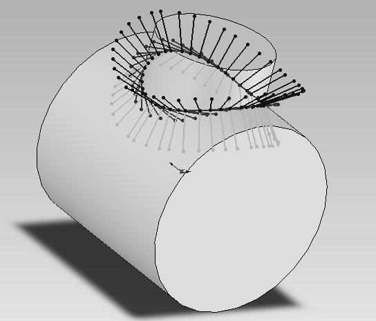
4 Vol. 3, No. 7 Modern Applied Science small room where three pipes intersected, so coordinate rotation angle of these path points through area round this point should be adjusted. Fig4-(b) shows that the planning path is made up of two semi-circle arcs and two straight-line portions. The welding path is plane curve. The main difficulty is that the welding torch must avoid to colliding the outline of model. The fig.4 -(c) displays a complexity work piece; this model is found in a SolidWorks textbook. It has all kinds space curve such as straight-line portion, arc and rational b-spline curve in the program, includes the cylinder intersecting with cylinder, cylinder intersecting with sphere, plane intersecting with cylinder, plane intersecting with sphere. Further more it must considering that welding torch need to keep off pedestal of main body between joint and cylinder. Fig.4-(d) show normal structure in pipes that pipe welding on flange and welding path be a circle. 5. Conclusions This paper has presented a practical CAD-based path automatic generation method for welding robots, which is based on the B-spline approximation of the welding seam. With this method, planar seams, as well as 3D seams, especially the intersection of two free-form surfaces can be extracted. With this method, the quality, the flexibility and the productivity of the welding robots can be increased. With this method, the complexity of robot programming, the time used to programming would be reduced. It also enhanced the capacity of welding robot. Those irregular shaped and contoured parts can be welded. In addition, this method also suits for many other robot applications, such as painting robot, and grasping robot. 1) A VBA program is programmed in the SolidWorks API. The main function of this software is planning the path and posture of welding torch automatically. Some typical work pieces are used in the experimental simulation to prove the validity of this method. 2)The defects of this software are that the automation level of software is still low because the path points on the work piece must be picked up manually; and for most complex space curve, one time in program calculation only could calculate the data of one entity curve, it will increase the complexity and discontinuity. These short points could be overcome in future. References Berger, U, Lepratti, R., May, M. (2005). An approach for the automatic generation of robot paths from CAD-Data. Emerging Technologies and Factory Automation 10 th IEEE Conference, Ding, Han, Huang, Lonlin, Xiong, Youlun. (1991). Computer-aided off-line planning of robot motion. Robotics and Autonomous Systems, 1991, 7(4): GB/T , Initial Graphics Exchange Specification. General Administration of Technology Supervision of the People s Republic of China,1993 Heng, Shengjie. (2006). Information. SolidWorks 2006 from proficiency to accidence. Beijing: E-China Youth Press, Li, xiang. (2006). Research of off-line programming system of arc robot based on ROBOGUIDE[D]. Tianjin Polytechnic University. Liu, Yong, Wang, Kehong, Du, Shanshan, (2002). The Study of Geometric Model of Typed Workpiece Welded in Robot. MACHINE BUILDING & AUTOMATION, 2002, 2, Prof..J D Lane. (1987). International trend in manufacturing technology. Robotic Welding, 1987: P5. Wang, Kehong, Liu, Yong, Yu, Jin, (2003). Study of geometric model and attitude of typical workpiece welded in robot. ELECTRIC WELDING MACHINE, 2003,33 (06), Zhang, Quanhuo, Zhang, Jianda, (2003). Computer Graphics. Bei Jing:, China Machine Press, Table 1. the data of planning results of two cylinders n x/mm y/mm z/mm w p r


5 Figure 1. the space curve obtained from SolidWorks Figure 2. the functions of the automatic posture planning software (a) the planning result of two cylinders 125


6 Vol. 3, No. 7 Modern Applied Science (b) the welding process simulation in ROBOGUIDE (c) the fact welding experiment Figure 3. the planning result and simulation (a) three cylinders in one work piece (b) a work piece of racetrack shape 126
 the cylinder and flange")

7 (c) a complexity work piece (d) the cylinder and flange Figure 4. the planning results of some complexity work piece 127
A Comprehensive Introduction to SolidWorks 2011
 A Comprehensive Introduction to SolidWorks 2011 Godfrey Onwubolu, Ph.D. SDC PUBLICATIONS www.sdcpublications.com Schroff Development Corporation Chapter 2 Geometric Construction Tools Objectives: When
Path planning and kinematics simulation of surfacing cladding for hot forging die
 MATEC Web of Conferences 21, 08005 (2015) DOI: 10.1051/matecconf/20152108005 C Owned by the authors, published by EDP Sciences, 2015 Path planning and kinematics simulation of surfacing cladding for hot
Operation Trajectory Control of Industrial Robots Based on Motion Simulation
 Operation Trajectory Control of Industrial Robots Based on Motion Simulation Chengyi Xu 1,2, Ying Liu 1,*, Enzhang Jiao 1, Jian Cao 2, Yi Xiao 2 1 College of Mechanical and Electronic Engineering, Nanjing
Shape Control of Cubic H-Bézier Curve by Moving Control Point
 Journal of Information & Computational Science 4: 2 (2007) 871 878 Available at http://www.joics.com Shape Control of Cubic H-Bézier Curve by Moving Control Point Hongyan Zhao a,b, Guojin Wang a,b, a Department
Keyword: Quadratic Bézier Curve, Bisection Algorithm, Biarc, Biarc Method, Hausdorff Distances, Tolerance Band.
 Department of Computer Science Approximation Methods for Quadratic Bézier Curve, by Circular Arcs within a Tolerance Band Seminar aus Informatik Univ.-Prof. Dr. Wolfgang Pree Seyed Amir Hossein Siahposhha
Study on Gear Chamfering Method based on Vision Measurement
 International Conference on Informatization in Education, Management and Business (IEMB 2015) Study on Gear Chamfering Method based on Vision Measurement Jun Sun College of Civil Engineering and Architecture,
Geometric Modeling Systems
 Geometric Modeling Systems Wireframe Modeling use lines/curves and points for 2D or 3D largely replaced by surface and solid models Surface Modeling wireframe information plus surface definitions supports
Based on the cross section contour surface model reconstruction
 International Journal of Research in Engineering and Science (IJRES) ISSN (Online): 2320-9364, ISSN (Print): 2320-9356 Volume 3 Issue 12 ǁ December. 2015 ǁ PP.07-12 Based on the cross section contour surface
Flank Millable Surface Design with Conical and Barrel Tools
 461 Computer-Aided Design and Applications 2008 CAD Solutions, LLC http://www.cadanda.com Flank Millable Surface Design with Conical and Barrel Tools Chenggang Li 1, Sanjeev Bedi 2 and Stephen Mann 3 1
Design and Communication Graphics
 An approach to teaching and learning Design and Communication Graphics Solids in Contact Syllabus Learning Outcomes: Construct views of up to three solids having curved surfaces and/or plane surfaces in
Virtual Engineering: Model based Off-line Programming Method for Industrial Robot
 Virtual Engineering: Model based Off-line Programming Method for Industrial Robot Xingguo Yin, Li Tao ABB Corporate Research China No. 31 Fu Te Dong Dan Rd., Waigaoqiao Free Trade Zone, 200131 Shanghai,
101. Design and realization of virtual prototype of shotcrete robot based on OpenGL
 101. Design and realization of virtual prototype of shotcrete robot based on OpenGL Pei-si Zhong 1, Yi Zheng 2, Kun-hua Liu 3 1, 2, 3 Shandong University of Science and Technology, Qingdao, China 2 Qingdao
7 Fractions. Number Sense and Numeration Measurement Geometry and Spatial Sense Patterning and Algebra Data Management and Probability
 7 Fractions GRADE 7 FRACTIONS continue to develop proficiency by using fractions in mental strategies and in selecting and justifying use; develop proficiency in adding and subtracting simple fractions;
Properties of a Circle Diagram Source:
 Properties of a Circle Diagram Source: http://www.ricksmath.com/circles.html Definitions: Circumference (c): The perimeter of a circle is called its circumference Diameter (d): Any straight line drawn
Interactive Graphics. Lecture 9: Introduction to Spline Curves. Interactive Graphics Lecture 9: Slide 1
 Interactive Graphics Lecture 9: Introduction to Spline Curves Interactive Graphics Lecture 9: Slide 1 Interactive Graphics Lecture 13: Slide 2 Splines The word spline comes from the ship building trade
LECTURE #6. Geometric Modelling for Engineering Applications. Geometric modeling for engineering applications
 LECTURE #6 Geometric modeling for engineering applications Geometric Modelling for Engineering Applications Introduction to modeling Geometric modeling Curve representation Hermite curve Bezier curve B-spline
Module 1: Basics of Solids Modeling with SolidWorks
 Module 1: Basics of Solids Modeling with SolidWorks Introduction SolidWorks is the state of the art in computer-aided design (CAD). SolidWorks represents an object in a virtual environment just as it exists
Research on Measuring and Optimization Method of Dynamic Accuracy of CNC Machine Tools
 Sensors & Transducers 2014 by IFSA Publishing, S. L. http://www.sensorsportal.com Research on Measuring and Optimization Method of Dynamic Accuracy of CNC Machine Tools 1, 2 Zhiming FENG, 2 Guofu YIN,
Computergrafik. Matthias Zwicker Universität Bern Herbst 2016
 Computergrafik Matthias Zwicker Universität Bern Herbst 2016 Today Curves NURBS Surfaces Parametric surfaces Bilinear patch Bicubic Bézier patch Advanced surface modeling 2 Piecewise Bézier curves Each
Rational Bezier Curves
 Rational Bezier Curves Use of homogeneous coordinates Rational spline curve: define a curve in one higher dimension space, project it down on the homogenizing variable Mathematical formulation: n P(u)
Note on Industrial Applications of Hu s Surface Extension Algorithm
 Note on Industrial Applications of Hu s Surface Extension Algorithm Yu Zang, Yong-Jin Liu, and Yu-Kun Lai Tsinghua National Laboratory for Information Science and Technology, Department of Computer Science
A story about Non Uniform Rational B-Splines. E. Shcherbakov
 A story about Non Uniform Rational B-Splines E. Shcherbakov Speakers 09-06: B-spline curves (W. Dijkstra) 16-06: NURBS (E. Shcherbakov) 30-06: B-spline surfaces (M. Patricio) Seminar 16-06-2004 2 Outline
Study on Tool Interference Checking for Complex Surface Machining
 2017 International Conference on Mechanical Engineering and Control Automation (ICMECA 2017) ISBN: 978-1-60595-449-3 Study on Tool Interference Checking for Complex Surface Machining Li LI 1,3,a, Li-Jin
Computergrafik. Matthias Zwicker. Herbst 2010
 Computergrafik Matthias Zwicker Universität Bern Herbst 2010 Today Curves NURBS Surfaces Parametric surfaces Bilinear patch Bicubic Bézier patch Advanced surface modeling Piecewise Bézier curves Each segment
NURBS: Non-Uniform Rational B-Splines AUI Course Denbigh Starkey
 NURBS: Non-Uniform Rational B-Splines AUI Course Denbigh Starkey 1. Background 2 2. Definitions 3 3. Using NURBS to define a circle 4 4. Homogeneous coordinates & control points at infinity 9 5. Constructing
Reconstruction of 3D Interacting Solids of Revolution from 2D Orthographic Views
 Reconstruction of 3D Interacting Solids of Revolution from 2D Orthographic Views Hanmin Lee, Soonhung Han Department of Mechanical Engeneering Korea Advanced Institute of Science & Technology 373-1, Guseong-Dong,
MOTION TRAJECTORY PLANNING AND SIMULATION OF 6- DOF MANIPULATOR ARM ROBOT
 MOTION TRAJECTORY PLANNING AND SIMULATION OF 6- DOF MANIPULATOR ARM ROBOT Hongjun ZHU ABSTRACT:In order to better study the trajectory of robot motion, a motion trajectory planning and simulation based
Research of Multi-axis NC Machining Method of Cylindrical Cam Based on UG NX
 Research of Multi-axis NC Machining Method of Cylindrical Cam Based on UG NX Qianhua Liang Electro-machinery Engineering Department, Chengdu Industrial Vocational Technical College, Sichuan, China Corresponding
CAGD PACKAGE FOR MATHEMATICA AND ITS USAGE IN THE TEACHING
 5. KONFERENCE O GEOMETRII A POČÍTAČOVÉ GRAFICE Bohumír Bastl CAGD PACKAGE FOR MATHEMATICA AND ITS USAGE IN THE TEACHING Abstract This talk presents a new package for Wolfram s Mathematica which provides
Bezier Curves. An Introduction. Detlef Reimers
 Bezier Curves An Introduction Detlef Reimers detlefreimers@gmx.de http://detlefreimers.de September 1, 2011 Chapter 1 Bezier Curve Basics 1.1 Linear Interpolation This section will give you a basic introduction
Computer Graphics. Curves and Surfaces. Hermite/Bezier Curves, (B-)Splines, and NURBS. By Ulf Assarsson
Splines, and NURBS. By Ulf Assarsson") Computer Graphics Curves and Surfaces Hermite/Bezier Curves, (B-)Splines, and NURBS By Ulf Assarsson Most of the material is originally made by Edward Angel and is adapted to this course by Ulf Assarsson.
Computer Graphics Curves and Surfaces Hermite/Bezier Curves, (B-)Splines, and NURBS By Ulf Assarsson Most of the material is originally made by Edward Angel and is adapted to this course by Ulf Assarsson.
ISE 422/ME 478/ISE 522 Robotic Systems
 ISE 422/ME 478/ISE 522 Robotic Systems Overview of Course R. Van Til Industrial & Systems Engineering Dept. Oakland University 1 What kind of robots will be studied? This kind Not this kind 2 Robots Used
Design considerations
 Curves Design considerations local control of shape design each segment independently smoothness and continuity ability to evaluate derivatives stability small change in input leads to small change in
Cmm-based Profile Measuring Method for Unknown Screw Compressor Rotor
 The 2nd International Conference on Computer Application and System Modeling (202) Cmm-based Profile Measuring Method for Unknown Screw Compressor Rotor Ji Xiaogang School of Mechanical Engineering, Jiangnan
Until now we have worked with flat entities such as lines and flat polygons. Fit well with graphics hardware Mathematically simple
 Curves and surfaces Escaping Flatland Until now we have worked with flat entities such as lines and flat polygons Fit well with graphics hardware Mathematically simple But the world is not composed of
OUTLINE. Quadratic Bezier Curves Cubic Bezier Curves
 BEZIER CURVES 1 OUTLINE Introduce types of curves and surfaces Introduce the types of curves Interpolating Hermite Bezier B-spline Quadratic Bezier Curves Cubic Bezier Curves 2 ESCAPING FLATLAND Until
Space Robot Path Planning for Collision Avoidance
 Space Robot Path Planning for ollision voidance Yuya Yanoshita and Shinichi Tsuda bstract This paper deals with a path planning of space robot which includes a collision avoidance algorithm. For the future
Research on time optimal trajectory planning of 7-DOF manipulator based on genetic algorithm
 Acta Technica 61, No. 4A/2016, 189 200 c 2017 Institute of Thermomechanics CAS, v.v.i. Research on time optimal trajectory planning of 7-DOF manipulator based on genetic algorithm Jianrong Bu 1, Junyan
Trajectory planning in Cartesian space
 Robotics 1 Trajectory planning in Cartesian space Prof. Alessandro De Luca Robotics 1 1 Trajectories in Cartesian space! in general, the trajectory planning methods proposed in the joint space can be applied
Virtual Interaction System Based on Optical Capture
 Sensors & Transducers 203 by IFSA http://www.sensorsportal.com Virtual Interaction System Based on Optical Capture Peng CHEN, 2 Xiaoyang ZHOU, 3 Jianguang LI, Peijun WANG School of Mechanical Engineering,
Intro to Modeling Modeling in 3D
 Intro to Modeling Modeling in 3D Polygon sets can approximate more complex shapes as discretized surfaces 2 1 2 3 Curve surfaces in 3D Sphere, ellipsoids, etc Curved Surfaces Modeling in 3D ) ( 2 2 2 2
COMPUTER AIDED ENGINEERING DESIGN (BFF2612)
") COMPUTER AIDED ENGINEERING DESIGN (BFF2612) BASIC MATHEMATICAL CONCEPTS IN CAED by Dr. Mohd Nizar Mhd Razali Faculty of Manufacturing Engineering mnizar@ump.edu.my COORDINATE SYSTEM y+ y+ z+ z+ x+ RIGHT
COMPUTER AIDED ENGINEERING DESIGN (BFF2612) BASIC MATHEMATICAL CONCEPTS IN CAED by Dr. Mohd Nizar Mhd Razali Faculty of Manufacturing Engineering mnizar@ump.edu.my COORDINATE SYSTEM y+ y+ z+ z+ x+ RIGHT
Review 1. Richard Koch. April 23, 2005
 Review Richard Koch April 3, 5 Curves From the chapter on curves, you should know. the formula for arc length in section.;. the definition of T (s), κ(s), N(s), B(s) in section.4. 3. the fact that κ =
Module 1 Session 1 HS. Critical Areas for Traditional Geometry Page 1 of 6
 Critical Areas for Traditional Geometry Page 1 of 6 There are six critical areas (units) for Traditional Geometry: Critical Area 1: Congruence, Proof, and Constructions In previous grades, students were
Curves and Surfaces 1
 Curves and Surfaces 1 Representation of Curves & Surfaces Polygon Meshes Parametric Cubic Curves Parametric Bi-Cubic Surfaces Quadric Surfaces Specialized Modeling Techniques 2 The Teapot 3 Representing
Central issues in modelling
 Central issues in modelling Construct families of curves, surfaces and volumes that can represent common objects usefully; are easy to interact with; interaction includes: manual modelling; fitting to
Progressive Surface Modeling Based On 3D Motion Sketch
 Progressive Surface Modeling Based On 3D Motion Sketch SHENGFENG IN, and DAVID K WRIGHT School of Engineering and Design Brunel University Uxbridge, Middlesex UB8 3PH UK Abstract: - This paper presents
Fall CSCI 420: Computer Graphics. 4.2 Splines. Hao Li.
 Fall 2014 CSCI 420: Computer Graphics 4.2 Splines Hao Li http://cs420.hao-li.com 1 Roller coaster Next programming assignment involves creating a 3D roller coaster animation We must model the 3D curve
PITSCO Math Individualized Prescriptive Lessons (IPLs)
") Orientation Integers 10-10 Orientation I 20-10 Speaking Math Define common math vocabulary. Explore the four basic operations and their solutions. Form equations and expressions. 20-20 Place Value Define
Orientation Integers 10-10 Orientation I 20-10 Speaking Math Define common math vocabulary. Explore the four basic operations and their solutions. Form equations and expressions. 20-20 Place Value Define
Modeling Body Motion Posture Recognition Using 2D-Skeleton Angle Feature
 2012 International Conference on Image, Vision and Computing (ICIVC 2012) IPCSIT vol. 50 (2012) (2012) IACSIT Press, Singapore DOI: 10.7763/IPCSIT.2012.V50.1 Modeling Body Motion Posture Recognition Using
Parameter Modeling for Single Screw Pump Based On CATIA Secondary Development Platform Heng Fu 1,a, Yanhua Gu 2,b *, Xiaoyu Wang 3,b, Xiu Fang Zhang 4
 5th International Conference on Advanced Engineering Materials and Technology (AEMT 205) Parameter Modeling for Single Screw Pump Based On CATIA Secondary Development Platform Heng Fu,a, Yanhua Gu 2,b
Geometric Entities for Pilot3D. Copyright 2001 by New Wave Systems, Inc. All Rights Reserved
 Geometric Entities for Pilot3D Copyright 2001 by New Wave Systems, Inc. All Rights Reserved Introduction on Geometric Entities for Pilot3D The best way to develop a good understanding of any Computer-Aided
3D Modeling Parametric Curves & Surfaces
 3D Modeling Parametric Curves & Surfaces Shandong University Spring 2012 3D Object Representations Raw data Point cloud Range image Polygon soup Solids Voxels BSP tree CSG Sweep Surfaces Mesh Subdivision
Real-Time 3D Tool Path Generation for Numerical Control
 Real-Time 3D Tool Path Generation for Numerical Control Gyula Hermann John von Neumann Faculty of Information Technology, Budapest Polytechnic H-1034 Nagyszombat utca 19 Budapest Hungary, hermgy@iif.hu
COLLISION-FREE TRAJECTORY PLANNING FOR MANIPULATORS USING GENERALIZED PATTERN SEARCH
 ISSN 1726-4529 Int j simul model 5 (26) 4, 145-154 Original scientific paper COLLISION-FREE TRAJECTORY PLANNING FOR MANIPULATORS USING GENERALIZED PATTERN SEARCH Ata, A. A. & Myo, T. R. Mechatronics Engineering
GDL Toolbox 2 Reference Manual
 Reference Manual Archi-data Ltd. Copyright 2002. New Features Reference Manual New Save GDL command Selected GDL Toolbox elements can be exported into simple GDL scripts. During the export process, the
Geometry. Cluster: Experiment with transformations in the plane. G.CO.1 G.CO.2. Common Core Institute
 Geometry Cluster: Experiment with transformations in the plane. G.CO.1: Know precise definitions of angle, circle, perpendicular line, parallel line, and line segment, based on the undefined notions of
ME 115(b): Final Exam, Spring
: Final Exam, Spring") ME 115(b): Final Exam, Spring 2011-12 Instructions 1. Limit your total time to 5 hours. That is, it is okay to take a break in the middle of the exam if you need to ask me a question, or go to dinner,
ME 115(b): Final Exam, Spring 2011-12 Instructions 1. Limit your total time to 5 hours. That is, it is okay to take a break in the middle of the exam if you need to ask me a question, or go to dinner,
Dgp _ lecture 2. Curves
 Dgp _ lecture 2 Curves Questions? This lecture will be asking questions about curves, their Relationship to surfaces, and how they are used and controlled. Topics of discussion will be: Free form Curves
Gardener s spline curve
 Annales Mathematicae et Informaticae 47 (017) pp. 109 118 http://ami.uni-eszterhazy.hu Gardener s spline curve Imre Juhász Department of Descriptive Geometry University of Miskolc agtji@uni-miskolc.hu
Strategy. Using Strategy 1
 Strategy Using Strategy 1 Scan Path / Strategy It is important to visualize the scan path you want for a feature before you begin taking points on your part. You want to try to place your points in a way
Lecture 9: Introduction to Spline Curves
 Lecture 9: Introduction to Spline Curves Splines are used in graphics to represent smooth curves and surfaces. They use a small set of control points (knots) and a function that generates a curve through
3D Modeling Parametric Curves & Surfaces. Shandong University Spring 2013
 3D Modeling Parametric Curves & Surfaces Shandong University Spring 2013 3D Object Representations Raw data Point cloud Range image Polygon soup Surfaces Mesh Subdivision Parametric Implicit Solids Voxels
Curves. Computer Graphics CSE 167 Lecture 11
 Curves Computer Graphics CSE 167 Lecture 11 CSE 167: Computer graphics Polynomial Curves Polynomial functions Bézier Curves Drawing Bézier curves Piecewise Bézier curves Based on slides courtesy of Jurgen
Design of three-dimensional photoelectric stylus micro-displacement measuring system
 Available online at www.sciencedirect.com Procedia Engineering 15 (011 ) 400 404 Design of three-dimensional photoelectric stylus micro-displacement measuring system Yu Huan-huan, Zhang Hong-wei *, Liu
Mathematically, the path or the trajectory of a particle moving in space in described by a function of time.
 Module 15 : Vector fields, Gradient, Divergence and Curl Lecture 45 : Curves in space [Section 45.1] Objectives In this section you will learn the following : Concept of curve in space. Parametrization
An introduction to interpolation and splines
 An introduction to interpolation and splines Kenneth H. Carpenter, EECE KSU November 22, 1999 revised November 20, 2001, April 24, 2002, April 14, 2004 1 Introduction Suppose one wishes to draw a curve
BobCAD CAM V25 4 Axis Standard Posted by Al /09/20 22:03
 BobCAD CAM V25 4 Axis Standard Posted by Al - 2012/09/20 22:03 Many BobCAD CAM clients that run a 4 axis have requested to work directly with Solids or STL files. In the past we only offered 4 axis indexing
YEAR AT A GLANCE Student Learning Outcomes by Marking Period
 2014-2015 Term 1 Overarching/general themes: Tools to Build and Analyze Points, Lines and Angles Dates Textual References To Demonstrate Proficiency by the End of the Term Students Will : Marking Period
Content Standard 1: Numbers, Number Sense, and Computation
 Content Standard 1: Numbers, Number Sense, and Computation Place Value Fractions Comparing and Ordering Counting Facts Estimating and Estimation Strategies Determine an approximate value of radical and
Chapter 1. Linear Equations and Straight Lines. 2 of 71. Copyright 2014, 2010, 2007 Pearson Education, Inc.
 Chapter 1 Linear Equations and Straight Lines 2 of 71 Outline 1.1 Coordinate Systems and Graphs 1.4 The Slope of a Straight Line 1.3 The Intersection Point of a Pair of Lines 1.2 Linear Inequalities 1.5
ME COMPUTER AIDED DESIGN COMPUTER AIDED DESIGN 2 MARKS Q&A
 ME6501 - COMPUTER AIDED DESIGN COMPUTER AIDED DESIGN 2 MARKS Q&A Unit I 1. What is CAD? Computer aided design (CAD) is the technology concerned with the use of computer systems to assist the creation,
Computer Animation. Rick Parent
 Algorithms and Techniques Interpolating Values Animation Animator specified interpolation key frame Algorithmically controlled Physics-based Behavioral Data-driven motion capture Motivation Common problem:
MACHINING OF ARCHIMEDEAN SPIRAL BY PARAMETRIC PROGRAMMING
 International Journal of Modern Manufacturing Technologies ISSN 067 3604, Vol. VIII, No. / 016 MACHINING OF ARCHIMEDEAN SPIRAL BY PARAMETRIC PROGRAMMING Vratraj Joshi 1, Keyur Desai, Harit Raval 3 1 Department
Calypso Construction Features. Construction Features 1
 Calypso 1 The Construction dropdown menu contains several useful construction features that can be used to compare two other features or perform special calculations. Construction features will show up
3.3 Interpolation of rotations represented by quaternions
 3 S 3.3 Interpolation of rotations represented by quaternions : set of unit quaternions ; S :set of unit 3D vectors Interpolation will be performed on 3 S (direct linear interpolation produces nonlinear
COMPUTER AIDED GEOMETRIC DESIGN. Thomas W. Sederberg
 COMPUTER AIDED GEOMETRIC DESIGN Thomas W. Sederberg January 31, 2011 ii T. W. Sederberg iii Preface This semester is the 24 th time I have taught a course at Brigham Young University titled, Computer Aided
user manual vol. 2: modeling
 user manual vol. 2: modeling An Company solidthinking Release 8.0 User Manual Modeling - Volume 2 1993-2009 solidthinking Inc. Part N. 80-25041-10301 Copyright 1993-2009 solidthinking, Inc. All rights
VALLIAMMAI ENGINEERING COLLEGE
 VALLIAMMAI ENGINEERING COLLEGE SRM Nagar, Kattankulathur 603 203 DEPARTMENT OF MECHANICAL ENGINEERING QUESTION BANK M.E: CAD/CAM I SEMESTER ED5151 COMPUTER APPLICATIONS IN DESIGN Regulation 2017 Academic
Curves and Surfaces Computer Graphics I Lecture 10
 15-462 Computer Graphics I Lecture 10 Curves and Surfaces Parametric Representations Cubic Polynomial Forms Hermite Curves Bezier Curves and Surfaces [Angel 10.1-10.6] September 30, 2003 Doug James Carnegie
Trajectory Optimization of Composite-pipe Cutting Based on Robot. Harbin , China. Abstract
 , pp.35-4 http//dx.doi.org/10.1457/ijca.016.9.7.1 Trajectory Optimization of Composite-pipe Cutting Based on Robot Bo You 1, Kaixin Li 1, Jiazhong Xu 1, Ming Qiao 1, Bowen Zhang and Wenqiang Wang 1 College
Off-Line Programming Design of Robots Based on DXF Files Zhaoxin Chen 1,a, Jiming Yi 1,b*, Jun Liu 1,c, Yanfeng Lin 2,3,d
 Advanced Materials Research Submitted: 2014-06-12 ISSN: 1662-8985, Vol. 1039, pp 313-319 Accepted: 2014-07-14 doi:10.4028/www.scientific.net/amr.1039.313 Online: 2014-10-31 2014 Trans Tech Publications,
Robots are built to accomplish complex and difficult tasks that require highly non-linear motions.
 Path and Trajectory specification Robots are built to accomplish complex and difficult tasks that require highly non-linear motions. Specifying the desired motion to achieve a specified goal is often a
GEOMETRIC MODELING AND DYNAMIC SIMULATION OF INVOLUTE GEAR BY GENERATING METHOD
 PROCEEDINGS 13th INTERNATIONAL CONFERENCE ON GEOMETRY AND GRAPHICS August 4-8, 2008, Dresden (Germany ISBN: 978-3-86780-042-6 GEOMETRIC MODELING AND DYNAMIC SIMULATION OF INVOLUTE GEAR BY GENERATING METHOD
Dynamic Balance Design of the Rotating Arc Sensor Based on PSO Algorithm
 016 International Conference on Advanced Manufacture Technology and Industrial Application (AMTIA 016) ISBN: 978-1-60595-387-8 Dynamic Balance Design of the Rotating Arc Sensor Based on PSO Algorithm Ji-zhong
Unit 1: Area Find the value of the variable(s). If your answer is not an integer, leave it in simplest radical form.
. If your answer is not an integer, leave it in simplest radical form.") Name Per Honors Geometry / Algebra II B Midterm Review Packet 018-19 This review packet is a general set of skills that will be assessed on the midterm. This review packet MAY NOT include every possible
Name Per Honors Geometry / Algebra II B Midterm Review Packet 018-19 This review packet is a general set of skills that will be assessed on the midterm. This review packet MAY NOT include every possible
Design and Development of a High Speed Sorting System Based on Machine Vision Guiding
 Available online at www.sciencedirect.com Physics Procedia 25 (2012 ) 1955 1965 2012 International Conference on Solid State Devices and Materials Science Design and Development of a High Speed Sorting
Journal of Chemical and Pharmaceutical Research, 2015, 7(3): Research Article
: Research Article") Available online www.jocpr.com Journal of Chemical and Pharmaceutical esearch, 015, 7(3):175-179 esearch Article ISSN : 0975-7384 CODEN(USA) : JCPC5 Thread image processing technology research based on
Available online www.jocpr.com Journal of Chemical and Pharmaceutical esearch, 015, 7(3):175-179 esearch Article ISSN : 0975-7384 CODEN(USA) : JCPC5 Thread image processing technology research based on
Cs602-computer graphics MCQS MIDTERM EXAMINATION SOLVED BY ~ LIBRIANSMINE ~
 Cs602-computer graphics MCQS MIDTERM EXAMINATION SOLVED BY ~ LIBRIANSMINE ~ Question # 1 of 10 ( Start time: 08:04:29 PM ) Total Marks: 1 Sutherland-Hodgeman clipping algorithm clips any polygon against
B-Spline and NURBS Surfaces CS 525 Denbigh Starkey. 1. Background 2 2. B-Spline Surfaces 3 3. NURBS Surfaces 8 4. Surfaces of Rotation 9
 B-Spline and NURBS Surfaces CS 525 Denbigh Starkey 1. Background 2 2. B-Spline Surfaces 3 3. NURBS Surfaces 8 4. Surfaces of Rotation 9 1. Background In my preious notes I e discussed B-spline and NURBS
Quadric Surfaces. Six basic types of quadric surfaces: ellipsoid. cone. elliptic paraboloid. hyperboloid of one sheet. hyperboloid of two sheets
 Quadric Surfaces Six basic types of quadric surfaces: ellipsoid cone elliptic paraboloid hyperboloid of one sheet hyperboloid of two sheets hyperbolic paraboloid (A) (B) (C) (D) (E) (F) 1. For each surface,
Constructing Blending Surfaces for Two Arbitrary Surfaces
 MM Research Preprints, 14 28 MMRC, AMSS, Academia, Sinica, Beijing No. 22, December 2003 Constructing Blending Surfaces for Two Arbitrary Surfaces Jinsan Cheng and Xiao-Shan Gao 1) Institute of System
Make geometric constructions. (Formalize and explain processes)
") Standard 5: Geometry Pre-Algebra Plus Algebra Geometry Algebra II Fourth Course Benchmark 1 - Benchmark 1 - Benchmark 1 - Part 3 Draw construct, and describe geometrical figures and describe the relationships
Standard 5: Geometry Pre-Algebra Plus Algebra Geometry Algebra II Fourth Course Benchmark 1 - Benchmark 1 - Benchmark 1 - Part 3 Draw construct, and describe geometrical figures and describe the relationships
CS559 Computer Graphics Fall 2015
 CS559 Computer Graphics Fall 2015 Practice Final Exam Time: 2 hrs 1. [XX Y Y % = ZZ%] MULTIPLE CHOICE SECTION. Circle or underline the correct answer (or answers). You do not need to provide a justification
Unit Activity Correlations to Common Core State Standards. Geometry. Table of Contents. Geometry 1 Statistics and Probability 8
 Unit Activity Correlations to Common Core State Standards Geometry Table of Contents Geometry 1 Statistics and Probability 8 Geometry Experiment with transformations in the plane 1. Know precise definitions
Body Mold Setting and Motion Emulation Analysis of Steering Mechanism of Two Power Flow Tracked Vehicle based on CATIA
 Body Mold Setting and Motion Emulation Analysis of Steering Mechanism of Two Power Flow Tracked Vehicle based Yong Sun 1 2,Wen-zhe Li *2,Tian-zhi Fu 1,Hong-qiong Zhang 1 1. College of engineering, Northeast
Offset Triangular Mesh Using the Multiple Normal Vectors of a Vertex
 285 Offset Triangular Mesh Using the Multiple Normal Vectors of a Vertex Su-Jin Kim 1, Dong-Yoon Lee 2 and Min-Yang Yang 3 1 Korea Advanced Institute of Science and Technology, sujinkim@kaist.ac.kr 2 Korea
Measuring Lengths The First Fundamental Form
 Differential Geometry Lia Vas Measuring Lengths The First Fundamental Form Patching up the Coordinate Patches. Recall that a proper coordinate patch of a surface is given by parametric equations x = (x(u,
Using Algebraic Geometry to Study the Motions of a Robotic Arm
 Using Algebraic Geometry to Study the Motions of a Robotic Arm Addison T. Grant January 28, 206 Abstract In this study we summarize selected sections of David Cox, John Little, and Donal O Shea s Ideals,
- number of elements - complement linear, simple quadratic and cubic sequences - exponential sequences and - simple combinations of these
 IGCSE Mathematics Revision checklist 2016. Syllabus 1 Numbers, set notation and language 1 Identify and use: - natural s - prime s - square s - common factors (HCF) - common multiples (LCM) - rational