SYNRAD3D PHOTON PROPAGATION AND SCATTERING SIMULATIONS
|
|
|
- Shannon Reeves
- 6 years ago
- Views:
Transcription
1 ECLOUD PROCEEDINGS SYNRAD3D PHOTON PROPAGATION AND SCATTERING SIMULATIONS G. Dugan, D. Sagan, CLASSE, Cornell University, Ithaca, NY, US INTRODUCTION The Bmad software library [] has been used very successfully at Cornell for modeling relativistic charged particles in storage rings and linacs. Associated with this library are a number of programs used for lattice design and analysis. Recently, as part of the CESRTA program [], a new program that uses the Bmad library, called Synrad3D [3, 4], has been developed to track synchrotron radiation photons generated in storage rings and linacs. The motivation for developing Synrad3D was to estimate the energy and position distribution of photon absorption sites, which are critical inputs to codes which model the growth of electron clouds. Synrad3D includes scattering from the vacuum chamber walls, based on X-ray data from an LBNL database [5] for the smooth-surface reflectivity, and an analytical model [6, 7] for diffuse scattering from a surface with finite roughness. Synrad3D can handle any planar lattice and a wide variety of vacuum chamber profiles. In the following sections, the general approach used in Synrad3D will be described. The models used for the vacuum chamber, for specular reflection, and for diffuse reflection, will be described. Examples of the application to the program to predict the radiation environment in the CESRTA ring will be presented. Comparison of the scattering model with X-ray data from DAΦNE will be given. Finally, an application of the program to predict the radiation environment in the ILC damping ring will be shown. GENERAL APPROACH Synrad3D uses Monte Carlo techniques to generate simulated photons based on the standard synchrotron radiation formulas for charged beam particles traversing dipoles, quadrupoles and wigglers, in the lattice of an accelerator. Any planar lattice can be handled. The lattice can be specified using Bmad, MAD, or XSIF format [8]. Photons are generated with respect to the particle beam s closed orbit, so the effect of variations in the orbit can be studied. In a linear accelerator lattice, since there is no closed orbit, the orbit is calculated from the user supplied initial orbit. The particle beam size is also taken into account when generating the photon starting positions. The emittance needed to calculate the beam size can be supplied by the user or is calculated from the standard synchrotron radiation formulas. Work supported by the US National Science Foundation (PHY , PHY-467, and PHY-6866), and US Department of Energy height width_minus width y θ P r w (θ) width_plus Figure : Vacuum chamber model VACUUM CHAMBER MODEL ante_height_plus x The vacuum chamber wall is characterized at a number of longitudinal positions by its cross-section. The cross section model is shown in Fig.. As shown in the figure, antechambers can be included. A vacuum chamber wall cross-section may also be characterized as a general shape, by specifying points and connecting them with elliptical or linear segments. In between the cross-sections, linear interpolation or triangular meshing can be used. Linear interpolation is faster but is best suited for convex chamber shapes. If triangular meshing is used, the segments connecting the points defining a general shape must be linear. SCATTERING MODEL Simulated photons are tracked until they hit the vacuum chamber wall, where the probability of being scattered, and the scattering angle, are determined by their energy and angle of incidence. This section describes the scattering model. Specular reflection The smooth-surface reflectivity characterizes the probability of specular reflection when a photon strikes the wall. This reflectivity is a function of the incident angle, the photon energy, and the material properties of the surface. The reflectivity is entered into the program in the form of a table. The smooth-surface reflectivity model for a technical aluminum surface (a nm carbon film on an aluminum substrate), which is current default in the program, is illustrated in Fig.. It has been taken from an LBNL X-ray scattering database[5]. In the following subsections, we present four examples of Synrad3D photon production, transport and absorption simulations using CESRTA lattices and vacuum chambers. All scattering is specular only in these examples. 7
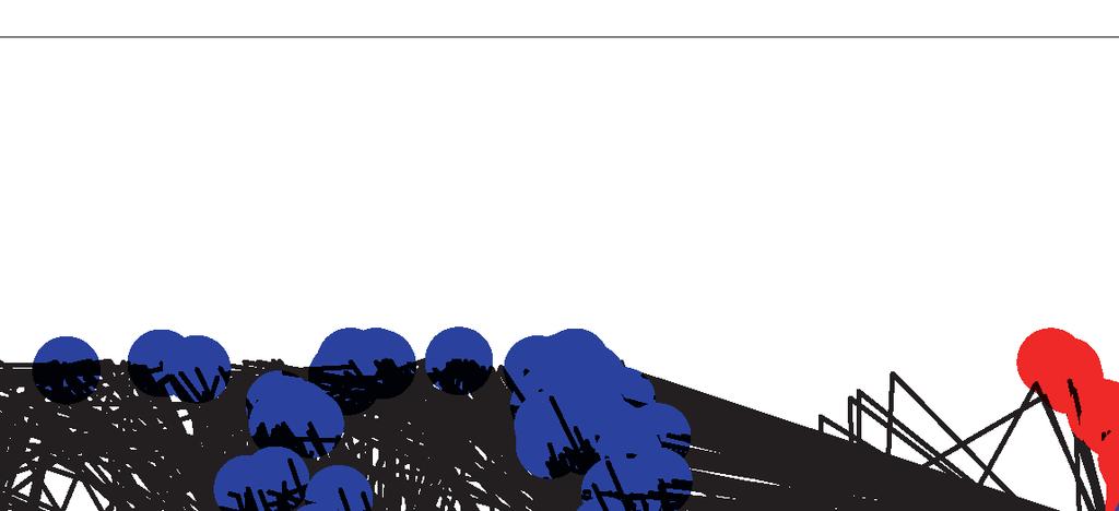
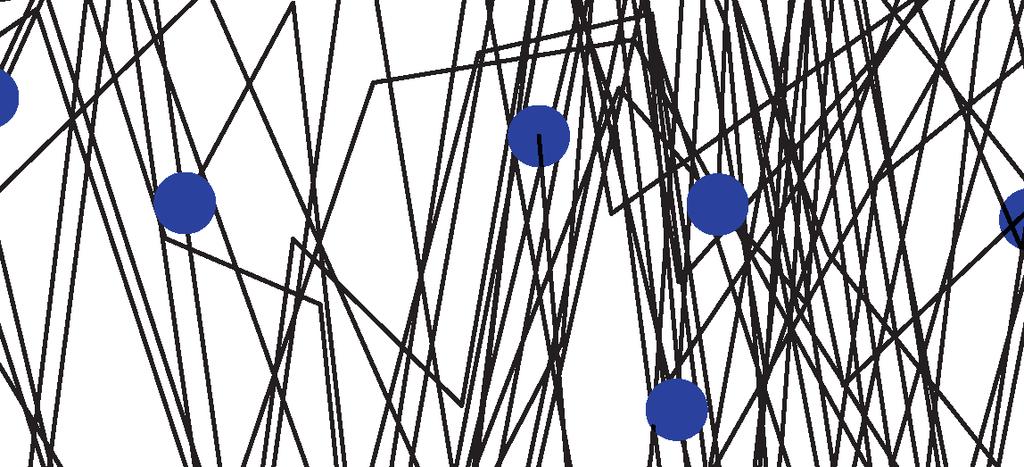
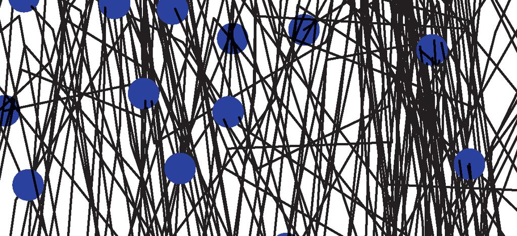
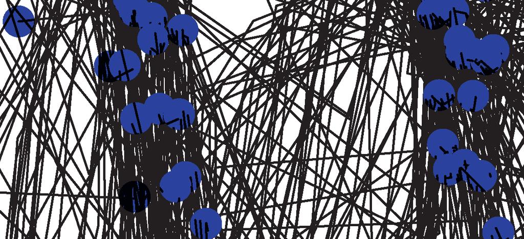
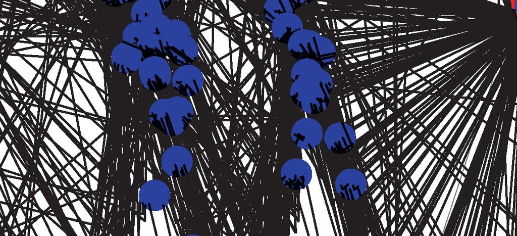
2 ECLOUD PROCEEDINGS. Smooth nm C layer on A substrate Incident grazing angle (deg) Reflectivity Photon Energy (ev) Figure : Smooth surface reflectivity for a nm C film on Al substrate: from [5] Example S: Photon Emission in a Dipole As the first example, we consider the CESRTA ring with a 5.3 GeV positron beam, and use Synrad3D to simulate photon emission only in one arc dipole. The vacuum chamber is a simple ellipse (dimensions 9 cm horizontal by 5 cm vertical).the photons are generated only in the upstream end of the dipole but propagate downstream and can scatter. In Fig. 3, we show a collection of photon trajectories, projected onto the bend plane. Photons generated by the beam strike the dipole vacuum chamber a short distance downstream. Some are absorbed here, but most scatter and strike the vacuum chamber further downstream, in the next Figure 3: Projections onto the bend plane of photon trajectories from radiation in a dipole. The red dots at the lower right are the photon source (the radiating beam in a section of the dipole). Black lines are projected photon trajectories, and blue dots are photon absorption sites. The green lines in the lower right are the edges of the vacuum chamber in the dipole; the red lines are the edges in a straight section, and the green lines on the left are the edges of the vacuum chamber in the next dipole. The geometry has been distorted for purposes of illustration. 8


3
4 ECLOUD PROCEEDINGS Counts QUADRUPOLE DRIFT Counts Final s (m) Final s (m) 4 SBEND WIGGLER 8 Counts 3 Counts Final s (m) Final s (m) Figure 7: Distribution of photon absorption sites vs. longitudinal position, for different magnetic environments. The origin for the longitudinal coordinate is the center of the L straight section. The ring circumference is about 76 m QUADRUPOLE DRIFT SBEND 5. WIGGLER Figure 8: Photon intensity distribution (in photons/meter/radian) vs. polar angle (measured around the vacuum chamber, with zero angle corresponding to the radial outside direction), averaged over each type of magnetic environment. A 9 cm (horizontal) by 5 cm (vertical) elliptical vacuum chamber profile is assumed throughout the ring, and all scattering is specular. Top-bottom symmetry is assumed.
5 ECLOUD PROCEEDINGS Example S: Photon emission throughout the ring, elliptical vacuum chamber, no diffuse scattering For the second example, photon emission throughout the CESRTA ring from a. GeV positron beam is simulated. (The lattice name is 85mev_956). The vacuum chamber is again a simple ellipse, and the scattering is purely specular. In Fig. 7, the distribution of photon absorption sites around the ring is shown, sorted by the type of magnetic environment in which the absorption occurs. This information is important for simulations of electron cloud growth, which is strongly influenced by the magnetic environment. The wigglers in the L straight section are responsible for the large peaks near s =. The large peaks near s = ±3 m are due to wigglers in the arcs near these locations. The small peaks in the arcs are due to the regular CESRTA dipoles. In Fig. 8, we present the photon intensity distribution (in photons/meter/radian) vs. polar angle (measured around the vacuum chamber, with zero angle corresponding to the radial outside direction), averaged over each type of magnetic environment. In the wigglers, most of the photons come from the radiation fans in an upstream wiggler region, so there are strong peaks on both edges of the vacuum chamber. In the bends, most of the radiation is from direct strikes from upstream dipoles, so there is only a strong peak on the radial outside edge, together with a long tail, due to scattering. In the quadrupoles and drifts, there are two peaks, with the higher one at the radial outside. The peak on the radial inside, and the distribution between the peaks, are due to scattering. Example S3: Photon emission throughout the ring, realistic vacuum chamber, no diffuse scattering For the third example, photon emission throughout the CESRTA ring from a. GeV positron beam is simulated again, but now with a realistic vacuum chamber profile. The scattering is purely specular, as in the previous example. In Fig. 9, we present the photon intensity distribution (in photons/meter/radian) vs. polar angle (measured around the vacuum chamber, with zero angle corresponding to the radial outside direction), averaged over each type of magnetic environment. Compared to the previous example, the photon intensity on the top and bottom of the chamber (polar angles of π/ and 3π/) is substantially suppressed, while the radiation striking the radial inside edge of the vacuum chamber (polar angle near π) is enhanced. This is primarily due to the local shape of the vacuum chamber at the strike point of the direct synchrotron radiation. For the elliptical chamber, the wall is curved at the radiation strike point, which, for a finite width radiation stripe, enhances scattering out of the median plane. For the real CESRTA chamber, for most of the ring, the wall is vertical at the radiation strike point, so scattering out of the median plane is reduced.. QUADRUPOLE. SBEND DRIFT WIGGLER. Figure 9: Photon intensity distribution (in photons/meter/radian) vs. polar angle (measured around the vacuum chamber, with zero angle corresponding to the radial outside direction), averaged over each type of magnetic environment. A realistic model for the CESRTA vacuum chamber throughout the ring is used. All scattering is specular. Top-bottom symmetry is assumed.
6 ECLOUD PROCEEDINGS Probability of specular reflection Specular reflection probability vs. energy and angle, for σ = nm Incident grazing angle (deg) Energy (ev) Figure : Specular reflection probability [6], vs. photon energy and angle, for an rms surface roughness of nm. Diffuse reflection Generally, the probability of specular reflection of a photon from a rough surface depends on the the rms surface roughness σ, the photon wavelength λ, and the grazing angle. An explicit formula for this probability is [6] in which P spec = e g(x,y), () g(x, y) = 4π σ (x + y) λ () where x is the cosine of the incident polar angle, and y is the cosine of the scattered polar angle. For a typical technical vacuum chamber surface, the rms surface roughness σ nm is greater than most of the X-ray wavelengths of interest, for all except the lowest energy photons. In this regime, except at very small grazing angles, diffuse scattering from the surface dominates over specular reflection. This is illustrated in Fig.. The theory of diffuse scattering of electromagnetic waves from random rough surfaces is a well-developed subject, and is covered in detail in references [6] and [7]. The model used in Synrad3D is based on scalar Kirchhoff theory; this model has been used successfully to describe the scattering of soft X-rays from metal surfaces [9, ]. In Synrad3D, we assume a Gaussian distribution for both the surface height variations (rms σ) and for the transverse distribution (equal in both transverse directions, with autocorrelation coefficient T ). The most general expression for the diffusely scattered power involves an infinite sum. This full expression is used in Synrad3D. However, the expression simplifies substantially in the limit g(x, y). This condition is satisfied for very rough surfaces, corresponding to technical vacuum chambers, and for high energy photons, for which typically σ λ. In this limit, the diffusely scattered power per unit solid angle is given by with dω = P R 4πy dp diff ( + xy) (x + y) 4 τ e ( x y )τ 4(x+y) ( a cos φ) e b cos φ, (3) a = b = h(x, y) + xy, (4) h(x, y)τ 4(x + y), (5) h(x, y) = (x + y ) + x y. (6) In this expression, P is the incident power, R is the smooth-surface reflectivity, and φ is the scattering angle out of the plane of incidence. Note that the relative power depends on the ratio τ = T/σ, and not on T or σ separately. The smooth-surface reflectivity R depends on the atomic structure of the surface materials (including any thin layers which may be deposited on the surface). The surface roughness parameters σ and T depend on the geometry of the surface deviations from a perfect plane. These parameters may be determined from inspection of the vacuum chamber surface, for example, using an atomic force microscope. Diffuse scattering distributions for 3 ev photons are shown in Fig. and Fig.. At this low photon energy, the approximation g(x, y) does not hold in general, and the full diffuse scattering formalism is used to compute these distributions. Diffuse scattering distributions for high energy photons, for which g(x, y) are shown in Fig. 3 and Fig. 4. These distributions have been computed from Eq. 3. In the following subsections, we present two examples of Synrad3D photon production, transport and absorption
7 ECLOUD PROCEEDINGS T Very rough diffuse scattering: σ = nm, = 7.5, energy = 3. ev σ Relative diffuse power/solid angle at ø = Scattered angle (deg) Incident grazing angles (deg) Figure : Diffuse scattering polar angular distributions for 3 ev photons. The full diffuse scattering expression has been used to calculate these curves. T Very rough diffuse scattering: σ = nm, = 7.5, energy = 3. ev σ Relative diffuse power/solid angle at specular angle Out-of-plane angle (deg) Incident grazing angles (deg) Figure : Diffuse scattering out-of-plane angular distributions for 3 ev photons. The full diffuse scattering expression has been used to calculate these curves. 3
8 ECLOUD PROCEEDINGS Very rough diffuse scattering: T = 7.5, High energy approximation σ Relative diffuse power/solid angle at ø = Scattered angle (deg) Incident grazing angles (deg) Figure 3: Diffuse scattering polar angular distributions for high energy photons. The curves are calculated from the approximate relation given in Eq. 3. T Very rough diffuse scattering: = 7.5, High energy approximation σ Relative diffuse power/solid angle at specular angle Out-of-plane angle (deg) Incident grazing angles (deg) Figure 4: Diffuse scattering out-of-plane angular distributions for high energy photons. The curves are calculated from the approximate relation given in Eq. 3. 4
9 ECLOUD PROCEEDINGS QUADRUPOLE DRIFT SBEND 5. WIGGLER Figure 5: Photon intensity distribution (in photons/meter/radian) vs. polar angle (measured around the vacuum chamber, with zero angle corresponding to the radial outside direction), averaged over each type of magnetic environment. A realistic model for the CESR vacuum chamber throughout the ring is used, and diffuse scattering is included. Top-bottom symmetry is assumed. simulations using CESRTA lattices and vacuum chambers, in which diffuse scattering is included in the simulation. Example D: Photon emission throughout the ring, realistic vacuum chamber, diffuse scattering included. For the first example, photon emission throughout the CESRTA ring from a. GeV positron beam is simulated again, with a realistic vacuum chamber profile. In this case, diffuse scattering is included, using the model described in the previous section. The surface roughness parameters used in the simulation were σ = nm and T = 5 nm. In Fig. 5, we present the photon intensity distribution (in photons/meter/radian) vs. polar angle (measured around the vacuum chamber, with zero angle corresponding to the radial outside direction), averaged over each type of magnetic environment. Compared to Example S3, with no diffuse scattering (see Fig. 9), the photon intensity on the top and bottom of the chamber (polar angles of π/ and 3π/) is now much higher, and is comparable to that seen in Example S. This is due to the out-of-plane diffuse scattering, which results in substantial amounts of radiation scattering out of the median plane. In addition, the radiation striking the radial inside edge of the vacuum chamber (polar angle near π) is also increased. Example D: Effect of variation of the diffuse scattering parameters For the second example, photon emission throughout the CESRTA ring from a. GeV positron beam is simulated again, with a realistic vacuum chamber profile. In this case, the effects of varying the diffuse scattering parameters is illustrated. In Fig. 6, the photon intensity distribution, averaged over each type of magnetic environment, is shown, for four different cases. The red points correspond to the diffuse scattering parameters σ = nm and T = 55 nm (same as Fig. 5). The black points correspond to pure specular reflection (same as Fig. 9). Two intermediate cases are also shown: the blue points correspond to still a rough surface, but with σ = nm, and T = 55 nm; and the cyan points correspond to a polished surface (σ = 4 nm, with T = nm). It can be seen that there is not much dependence on σ for the two rough surface cases. A polished surface gives considerably less scattering, as expected, but there is still a significant difference between this case and pure specular reflection. 5
10 ECLOUD PROCEEDINGS. QUADRUPOLE. SBEND DRIFT WIGGLER. Figure 6: Photon intensity distribution (in photons/meter/radian) vs. polar angle (measured around the vacuum chamber, with zero angle corresponding to the radial outside direction), averaged over each type of magnetic environment. A realistic model for the CESR vacuum chamber throughout the ring is used. The different colors correspond to: red, diffuse scattering parameters σ = nm and T = 55 nm; blue, diffuse scattering parameters σ = nm and T = 55 nm; cyan, diffuse scattering parameters σ = 4 nm and T = nm; black, pure specular scattering. Top-bottom symmetry is assumed. Benchmarking To provide guidance on the choice of smooth surface reflectivity for a technical aluminum vacuum chamber surface, and to provide an overall check on the scattering model used in Synrad3D, we have relied on measurements [] of X-ray scattering from an aluminum vacuum chamber surface made at DAΦNE. For these measurements, the rms surface roughness of the sample was reported to be nm. The Synrad3D scattering model was used to predict the measured X-ray reflectivity. The autocorrelation parameter T, together with the surface layer thickness and composition (which determine the smooth surface reflectivity, as tabulated in the LBNL X-ray database [5]), were treated as unknowns. (The substrate below the surface layer was assumed to be aluminum). These quantities were adjusted to give the best fit to the measurements. The best-fit value for the transverse autocorrelation parameter, T, was found to be 55 nm. The best fit surface layer was found to be a nm carbon layer. The assumption of an aluminum oxide surface layer was not consistent with the data. The data and the corresponding best fits are shown in Fig. 7 and 8. Reflectivity Diffuse scattering into detector: σ = nm, T = 55 nm 5 deg grazing angle Points: Daphne data Blue line: surface film nm C on A substrate Red line: surface film 4 nm A O 3 on A substrate. 3 4 Photon Energy (ev) Figure 7: Diffuse scattering at 5 deg from a surface layer on an aluminum substrate: comparison of data [] and model. 6
11
12
13 ECLOUD PROCEEDINGS REFERENCES [] D. Sagan, Design and Applications of the Bmad Library for the Simulation of Particle Beams and X-rays, in th International Computational Accelerator Physics Conference, Rostock-Warnemünde, Germany (). [] M. A. Palmer et al., The Conversion and Operation of the Cornell Electron Storage Ring as a Test Accelerator (CesrTA) for Damping Rings Research and Development, in Proceedings of the 9 Particle Accelerator Conference, Vancouver, BC (9), p [3] G. Dugan & D. Sagan, Synrad3D Photon Propagation and Scattering Simulation, in Proceedings of ECLOUD : 49th ICFA Advanced Beam Dynamics Workshop on Electron Cloud Physics, K. Smolenski, Ed., Ithaca, NY (in press), Paper PST8. [4] G. Dugan & D. Sagan, SYNRAD3D Photon Tracking Program, Tech. rep., Cornell University (), lepp.cornell.edu/~dcs6/synrad3d.pdf. [5] B. L. Henke, E. M. Gullikson & J. C. Davis, X-Ray Interactions: Photoabsorption, Scattering, Transmission, and Reflection at E = 5 3, ev, Z = 9, At. Data Nucl. Data Tables 54, p (Jul. 993). [6] P. Beckmann & A. Spizzichino, The Scattering of Electromagnetic Waves from Rough Surfaces, Pergamon Press, New York (963). [7] J. A. Ogilvy, Theory of Wave Scattering from Random Rough Surfaces, Hilger, Bristol (993). [8] D. Sagan, Bmad Manual, Tech. rep., Cornell University (), bmad/. [9] H. Hogrefe & C. Kunz, Soft X-Ray Scattering from Rough Surfaces: Experimental and Theoretical Analysis, Appl. Opt. 6, p (Jul. 987). [] R. J. Noll & P. Glenn, Mirror Surface Autocovariance Functions and their Associated Visible Scattering, Appl. Opt., p (May 98). [] N. Mahne et al., Experimental Determination of e- Cloud Simulation Input Parameters for DAΦNE, Tech. Rep. EUROTEV-REPORT-5-3, EU- ROTeV (5), presentations/eurotev_reports/5/e37/ EUROTeV-Report-5-3.pdf. [] J. A. Crittenden et al., Investigation into Electron Cloud Effects in the ILC Damping Ring Design, in Proceedings of the International Particle Accelerator Conference, New Orleans, LA (), p [3] G. Dugan et al., Observations and Predictions at CesrTA, and Outlook for ILC, in Proceedings of ECLOUD, La Biodola, Elba, Italy (). [4] J. A. Crittenden, Electron Cloud Buildup Characterization Using Shielded Pickup Measurements and Custom Modeling Code, in Proceedings of ECLOUD, La Biodola, Elba, Italy (). [5] L. Boon, Chamber Surface Roughness and Electron Cloud for the APS SCU, in Proceedings of ECLOUD, La Biodola, Elba, Italy (). 9
Synrad3D Photon propagation and scattering simulation
 Synrad3D Photon propagation and scattering simulation G. Dugan, D. Sagan CLASSE, Cornell University, Ithaca, NY 14853 USA Abstract As part of the Bmad software library, a program called Synrad3D has been
Synrad3D Photon Tracking Program. David Sagan and Gerry Dugan
 Synrad3D Photon Tracking Program David Sagan and Gerry Dugan August 8, 2018 Contents 1 Introduction 3 2 Running Synrad3D 4 2.1 Syntax.......................................... 4 2.2 -plot Option.......................................
Synrad: Program for Calculating Synchrotron Radiation Power
 Synrad: Program for Calculating Synchrotron Radiation Power February 23, 2017 1 Introduction Synrad is a program for calculating the synchrotron radiation power deposition on the beam chamber walls in
Effective Medium Theory, Rough Surfaces, and Moth s Eyes
 Effective Medium Theory, Rough Surfaces, and Moth s Eyes R. Steven Turley, David Allred, Anthony Willey, Joseph Muhlestein, and Zephne Larsen Brigham Young University, Provo, Utah Abstract Optics in the
Dynamical Theory of X-Ray Diffraction
 Dynamical Theory of X-Ray Diffraction ANDRE AUTHIER Universite P. et M. Curie, Paris OXFORD UNIVERSITY PRESS Contents I Background and basic results 1 1 Historical developments 3 1.1 Prologue 3 1.2 The
Light and Electromagnetic Waves. Honors Physics
 Light and Electromagnetic Waves Honors Physics Electromagnetic Waves EM waves are a result of accelerated charges and disturbances in electric and magnetic fields (Radio wave example here) As electrons
Light. Form of Electromagnetic Energy Only part of Electromagnetic Spectrum that we can really see
 Light Form of Electromagnetic Energy Only part of Electromagnetic Spectrum that we can really see Facts About Light The speed of light, c, is constant in a vacuum. Light can be: REFLECTED ABSORBED REFRACTED
Accelerator Modeling. David Sagan Cornell University. Jlab ERL Workshop, March 19-23, 2005 David Sagan -1-
 Accelerator Modeling David Sagan Cornell University Jlab ERL Workshop, March 19-23, 2005 David Sagan -1- Cornell s s CESR Storage Ring E+ / E- Collider. In operation since 1979. Used for both HEP and as
Coupling of surface roughness to the performance of computer-generated holograms
 Coupling of surface roughness to the performance of computer-generated holograms Ping Zhou* and Jim Burge College of Optical Sciences, University of Arizona, Tucson, Arizona 85721, USA *Corresponding author:
CESR Synchrotron Radiation Tables
 CESR Synchrotron Radiation Tables Range of Photon Rates and Beta averaged Photon Rates Jim Crittenden Cornell Laboratory for Accelerator Based Sciences and Education Electron Cloud Simulations Meeting
Light. Electromagnetic wave with wave-like nature Refraction Interference Diffraction
 Light Electromagnetic wave with wave-like nature Refraction Interference Diffraction Light Electromagnetic wave with wave-like nature Refraction Interference Diffraction Photons with particle-like nature
Ray Optics I. Last time, finished EM theory Looked at complex boundary problems TIR: Snell s law complex Metal mirrors: index complex
 Phys 531 Lecture 8 20 September 2005 Ray Optics I Last time, finished EM theory Looked at complex boundary problems TIR: Snell s law complex Metal mirrors: index complex Today shift gears, start applying
6-1 LECTURE #6: OPTICAL PROPERTIES OF SOLIDS. Basic question: How do solids interact with light? The answers are linked to:
 LECTURE #6: OPTICAL PROPERTIES OF SOLIDS Basic question: How do solids interact with light? The answers are linked to: Properties of light inside a solid Mechanisms behind light reflection, absorption
specular diffuse reflection.
 Lesson 8 Light and Optics The Nature of Light Properties of Light: Reflection Refraction Interference Diffraction Polarization Dispersion and Prisms Total Internal Reflection Huygens s Principle The Nature
Simulation study for the EUDET pixel beam telescope
 EUDET Simulation study for the EUDET pixel beam telescope using ILC software T. Klimkovich January, 7 Abstract A pixel beam telescope which is currently under development within the EUDET collaboration
dq dt I = Irradiance or Light Intensity is Flux Φ per area A (W/m 2 ) Φ =
 Φ =") Radiometry (From Intro to Optics, Pedrotti -4) Radiometry is measurement of Emag radiation (light) Consider a small spherical source Total energy radiating from the body over some time is Q total Radiant
Radiometry (From Intro to Optics, Pedrotti -4) Radiometry is measurement of Emag radiation (light) Consider a small spherical source Total energy radiating from the body over some time is Q total Radiant
Measurement of the beam yz crabbing tilt due to wakefields using streak camera at CESR
 Journal of Physics: Conference Series PAPER OPEN ACCESS Measurement of the beam yz crabbing tilt due to wakefields using streak camera at CESR To cite this article: S T Wang and D L Rubin 018 J. Phys.:
dq dt I = Irradiance or Light Intensity is Flux Φ per area A (W/m 2 ) Φ =
 Φ =") Radiometry (From Intro to Optics, Pedrotti -4) Radiometry is measurement of Emag radiation (light) Consider a small spherical source Total energy radiating from the body over some time is Q total Radiant
Radiometry (From Intro to Optics, Pedrotti -4) Radiometry is measurement of Emag radiation (light) Consider a small spherical source Total energy radiating from the body over some time is Q total Radiant
Analysis of Cornell Electron-Positron Storage Ring Test Accelerator's Double Slit Visual Beam Size Monitor
 Analysis of Cornell Electron-Positron Storage Ring Test Accelerator's Double Slit Visual Beam Size Monitor Senior Project Department of Physics California Polytechnic State University San Luis Obispo By:
1 Introduction 2. 2 Defining magnetic regions Location, curvature and beam direction Beam width and divergence... 5
 Contents 1 Introduction 2 2 Defining magnetic regions 2 2.1 Location, curvature and beam direction............................ 4 2.2 Beam width and divergence................................... 5 3 Synchrotron
THE SCATTERING OF ELECTROMAGNETIC WAVES FROM ROUGH SURFACES
 THE SCATTERING OF ELECTROMAGNETIC WAVES FROM ROUGH SURFACES Petr Beckmann Andre Spizzichino CONTENTS Part I-THEORY By PETR BECKMANN 1. INTRODUCTION 2. QUALITATIVE CONSIDERATIONS 9 2.1. The Rayleigh Criterion
D&S Technical Note 09-2 D&S A Proposed Correction to Reflectance Measurements of Profiled Surfaces. Introduction
 Devices & Services Company 10290 Monroe Drive, Suite 202 - Dallas, Texas 75229 USA - Tel. 214-902-8337 - Fax 214-902-8303 Web: www.devicesandservices.com Email: sales@devicesandservices.com D&S Technical
LECTURE 37: Ray model of light and Snell's law
 Lectures Page 1 Select LEARNING OBJECTIVES: LECTURE 37: Ray model of light and Snell's law Understand when the ray model of light is applicable. Be able to apply Snell's Law of Refraction to any system.
Performance of the GlueX Detector Systems
 Performance of the GlueX Detector Systems GlueX-doc-2775 Gluex Collaboration August 215 Abstract This document summarizes the status of calibration and performance of the GlueX detector as of summer 215.
Radiometry (From Intro to Optics, Pedrotti 1-4) Radiometry is measurement of Emag radiation (light) Consider a small spherical source Assume a black
 Radiometry is measurement of Emag radiation (light) Consider a small spherical source Assume a black") Radiometry (From Intro to Optics, Pedrotti -4) Radiometry is measurement of Emag radiation (light) Consider a small spherical source Assume a black body type emitter: uniform emission Total energy radiating
Radiometry (From Intro to Optics, Pedrotti -4) Radiometry is measurement of Emag radiation (light) Consider a small spherical source Assume a black body type emitter: uniform emission Total energy radiating
CS 5625 Lec 2: Shading Models
 CS 5625 Lec 2: Shading Models Kavita Bala Spring 2013 Shading Models Chapter 7 Next few weeks Textures Graphics Pipeline Light Emission To compute images What are the light sources? Light Propagation Fog/Clear?
Topic 9: Lighting & Reflection models 9/10/2016. Spot the differences. Terminology. Two Components of Illumination. Ambient Light Source
 Topic 9: Lighting & Reflection models Lighting & reflection The Phong reflection model diffuse component ambient component specular component Spot the differences Terminology Illumination The transport
Parametric Study of a Two-Stage Betatron Collimation for the PS2
 Parametric Study of a Two-Stage Betatron Collimation for the PS2 Javier Barranco García, Yannis Papaphillipou CERN(BE/ABP) 30 th September 2010 Outline Why a Collimation System for PS2? Collimation Concept
Topic 9: Lighting & Reflection models. Lighting & reflection The Phong reflection model diffuse component ambient component specular component
 Topic 9: Lighting & Reflection models Lighting & reflection The Phong reflection model diffuse component ambient component specular component Spot the differences Terminology Illumination The transport
Modeling Custom Surface Roughness with LucidShape 2D Scatter Curve BSDF Material
 WHITE PAPER Modeling Custom Surface Roughness with LucidShape 2D Scatter Curve BSDF Material Author Andreas Bielawny, Ph.D. CAE Synopsys, Inc. Abstract LucidShape accurately simulates how light interacts
COMPUTER SIMULATION TECHNIQUES FOR ACOUSTICAL DESIGN OF ROOMS - HOW TO TREAT REFLECTIONS IN SOUND FIELD SIMULATION
 J.H. Rindel, Computer simulation techniques for the acoustical design of rooms - how to treat reflections in sound field simulation. ASVA 97, Tokyo, 2-4 April 1997. Proceedings p. 201-208. COMPUTER SIMULATION
Phys 102 Lecture 17 Introduction to ray optics
 Phys 102 Lecture 17 Introduction to ray optics 1 Physics 102 lectures on light Light as a wave Lecture 15 EM waves Lecture 16 Polarization Lecture 22 & 23 Interference & diffraction Light as a ray Lecture
At the interface between two materials, where light can be reflected or refracted. Within a material, where the light can be scattered or absorbed.
 At the interface between two materials, where light can be reflected or refracted. Within a material, where the light can be scattered or absorbed. The eye sees by focusing a diverging bundle of rays from
1.! Questions about reflected intensity. [Use the formulas on p. 8 of Light.] , no matter
![1.! Questions about reflected intensity. [Use the formulas on p. 8 of Light.] , no matter](/thumbs/81/83191942.jpg "1.! Questions about reflected intensity. [Use the formulas on p. 8 of Light.] , no matter") Reading: Light Key concepts: Huygens s principle; reflection; refraction; reflectivity; total reflection; Brewster angle; polarization by absorption, reflection and Rayleigh scattering. 1.! Questions about
Reading: Light Key concepts: Huygens s principle; reflection; refraction; reflectivity; total reflection; Brewster angle; polarization by absorption, reflection and Rayleigh scattering. 1.! Questions about
All forms of EM waves travel at the speed of light in a vacuum = 3.00 x 10 8 m/s This speed is constant in air as well
 Pre AP Physics Light & Optics Chapters 14-16 Light is an electromagnetic wave Electromagnetic waves: Oscillating electric and magnetic fields that are perpendicular to the direction the wave moves Difference
Klaus Dehmelt EIC Detector R&D Weekly Meeting November 28, 2011 GEM SIMULATION FRAMEWORK
 Klaus Dehmelt EIC Detector R&D Weekly Meeting November 28, 2011 GEM SIMULATION FRAMEWORK Overview GEM Simulation Framework in the context of Simulation Studies for a High Resolution Time Projection Chamber
Engineered Diffusers Intensity vs Irradiance
 Engineered Diffusers Intensity vs Irradiance Engineered Diffusers are specified by their divergence angle and intensity profile. The divergence angle usually is given as the width of the intensity distribution
Geometrical modeling of light scattering from paper substrates
 Geometrical modeling of light scattering from paper substrates Peter Hansson Department of Engineering ciences The Ångström Laboratory, Uppsala University Box 534, E-75 Uppsala, weden Abstract A light
Transmission Electron Microscopy 2. Scattering and Diffraction
 Transmission Electron Microscopy 2. Scattering and Diffraction EMA 6518 Spring 2007 01/07 Outline Why are we interested in electron scattering? Terminology of scattering The characteristics of electron
SESSION 5: INVESTIGATING LIGHT. Key Concepts. X-planation. Physical Sciences Grade In this session we:
 SESSION 5: INVESTIGATING LIGHT Key Concepts In this session we: Explain what light is, where light comes from and why it is important Identify what happens when light strikes the surface of different objects
Condenser Optics for Dark Field X-Ray Microscopy
 Condenser Optics for Dark Field X-Ray Microscopy S. J. Pfauntsch, A. G. Michette, C. J. Buckley Centre for X-Ray Science, Department of Physics, King s College London, Strand, London WC2R 2LS, UK Abstract.
Lecture 7 Notes: 07 / 11. Reflection and refraction
 Lecture 7 Notes: 07 / 11 Reflection and refraction When an electromagnetic wave, such as light, encounters the surface of a medium, some of it is reflected off the surface, while some crosses the boundary
Light and Sound. Wave Behavior and Interactions
 Light and Sound Wave Behavior and Interactions How do light/sound waves interact with matter? WORD Definition Example Picture REFLECTED REFRACTED is the change in direction of a wave when it changes speed
EUDET Telescope Geometry and Resolution Studies
 EUDET EUDET Telescope Geometry and Resolution Studies A.F.Żarnecki, P.Nieżurawski February 2, 2007 Abstract Construction of EUDET pixel telescope will significantly improve the test beam infrastructure
INFOGR Computer Graphics. J. Bikker - April-July Lecture 10: Shading Models. Welcome!
 INFOGR Computer Graphics J. Bikker - April-July 2016 - Lecture 10: Shading Models Welcome! Today s Agenda: Introduction Light Transport Materials Sensors Shading INFOGR Lecture 10 Shading Models 3 Introduction
1.6 Rough Surface Scattering Applications Computer Graphic Shading and Rendering
 20 Durgin ECE 3065 Notes Rough Surface Scattering Chapter 1 1.6 Rough Surface Scattering Applications 1.6.1 Computer Graphic Shading and Rendering At optical frequencies, nearly every object in our everyday
Lecture 4: Reflection Models
 Lecture 4: Reflection Models CS 660, Spring 009 Kavita Bala Computer Science Cornell University Outline Light sources Light source characteristics Types of sources Light reflection Physics-based models
π ± Charge Exchange Cross Section on Liquid Argon
 π ± Charge Exchange Cross Section on Liquid Argon Kevin Nelson REU Program, College of William and Mary Mike Kordosky College of William and Mary, Physics Dept. August 5, 2016 Abstract The observation
LIGHT. Speed of light Law of Reflection Refraction Snell s Law Mirrors Lenses
 LIGHT Speed of light Law of Reflection Refraction Snell s Law Mirrors Lenses Light = Electromagnetic Wave Requires No Medium to Travel Oscillating Electric and Magnetic Field Travel at the speed of light
Chapter 35. The Nature of Light and the Laws of Geometric Optics
 Chapter 35 The Nature of Light and the Laws of Geometric Optics Introduction to Light Light is basic to almost all life on Earth. Light is a form of electromagnetic radiation. Light represents energy transfer
Design of Electromagnetic Test Sites
 Sensor and Simulation Notes Note 533 3 August 2008 Design of Electromagnetic Test Sites Carl E. Baum University of New Mexico Department of Electrical and Computer Engineering Albuquerque New Mexico 87131
Supplementary Figure 1: Schematic of the nanorod-scattered wave along the +z. direction.
 Supplementary Figure 1: Schematic of the nanorod-scattered wave along the +z direction. Supplementary Figure 2: The nanorod functions as a half-wave plate. The fast axis of the waveplate is parallel to
Forward Time-of-Flight Geometry for CLAS12
 Forward Time-of-Flight Geometry for CLAS12 D.S. Carman, Jefferson Laboratory ftof geom.tex April 13, 2016 Abstract This document details the nominal geometry for the CLAS12 Forward Time-of- Flight System
Visual inspection of metal surfaces
 Visual inspection of metal surfaces by J. L. MUNDY General Electric Company Schenectady, New York INTRODUCTION The majotity of applications of automatic visual inspection have been the case in which a
Simulation Study for EUDET Pixel Beam Telescope using ILC Software
 Simulation Study for EUDET Pixel Beam Telescope using ILC Software Linear Collider Workshop, Hamburg, May/June 2007 Tatsiana Klimkovich DESY Tatsiana Klimkovich, Linear Collider Workshop, May/June 2007
Lecture Ray Model of Light. Physics Help Q&A: tutor.leiacademy.org
 Lecture 1201 Ray Model of Light Physics Help Q&A: tutor.leiacademy.org Reflection of Light A ray of light, the incident ray, travels in a medium. When it encounters a boundary with a second medium, part
MEASUREMENT OF SMALL TRANSVERSE BEAM SIZE USING INTERFEROMETRY
 MEASUREMENT OF SMALL TRANSVERSE BEAM SIZE USING INTERFEROMETRY T. Mitsuhashi High Energy Accelerator Research Organisation, Oho, Tsukuba, Ibaraki, 35-81 Japan Abstract The principle of measurement of the
Local Illumination. CMPT 361 Introduction to Computer Graphics Torsten Möller. Machiraju/Zhang/Möller
 Local Illumination CMPT 361 Introduction to Computer Graphics Torsten Möller Graphics Pipeline Hardware Modelling Transform Visibility Illumination + Shading Perception, Interaction Color Texture/ Realism
Philpot & Philipson: Remote Sensing Fundamentals Interactions 3.1 W.D. Philpot, Cornell University, Fall 12
 Philpot & Philipson: Remote Sensing Fundamentals Interactions 3.1 W.D. Philpot, Cornell University, Fall 1 3. EM INTERACTIONS WITH MATERIALS In order for an object to be sensed, the object must reflect,
3/10/2019. Models of Light. Waves and wave fronts. Wave fronts and rays
 Models of Light The wave model: Under many circumstances, light exhibits the same behavior as material waves. The study of light as a wave is called wave optics. The ray model: The properties of prisms,
Chapter 24. Wave Optics
 Chapter 24 Wave Optics Wave Optics The wave nature of light is needed to explain various phenomena Interference Diffraction Polarization The particle nature of light was the basis for ray (geometric) optics
1. Particle Scattering. Cogito ergo sum, i.e. Je pense, donc je suis. - René Descartes
 1. Particle Scattering Cogito ergo sum, i.e. Je pense, donc je suis. - René Descartes Generally gas and particles do not scatter isotropically. The phase function, scattering efficiency, and single scattering
Diffraction. Single-slit diffraction. Diffraction by a circular aperture. Chapter 38. In the forward direction, the intensity is maximal.
 Diffraction Chapter 38 Huygens construction may be used to find the wave observed on the downstream side of an aperture of any shape. Diffraction The interference pattern encodes the shape as a Fourier
Evaluation of radiative power loading on WEST metallic in-vessel components
 Evaluation of radiative power loading on WEST metallic in-vessel components M-H. Aumeunier 1, P. Moreau, J. Bucalossi, M. Firdaouss CEA/IRFM F-13108 Saint-Paul-Lez-Durance, France E-mail: marie-helene.aumeunier@cea.fr
THE TRIUMF OPTIMIZATION PLATFORM AND APPLICATION TO THE E-LINAC INJECTOR
 THE TRIUMF OPTIMIZATION PLATFORM AND APPLICATION TO THE E-LINAC INJECTOR C. Gong and Y.C. Chao TRIUMF, 4004 Wesbrook Mall, Vancouver V6T 2A3, Canada Abstract Multi-objective genetic algorithms (MOGA) have
Light: Geometric Optics
 Light: Geometric Optics The Ray Model of Light Light very often travels in straight lines. We represent light using rays, which are straight lines emanating from an object. This is an idealization, but
The roughness model in SHADOW
 The roughness model in SHADOW Introduction SHADOW contains a model for analysing the surface roughness. Surface roughness is defined as irregularities in the optical surface which produces dispersion (scattering)
Chapter 33 The Nature and Propagation of Light by C.-R. Hu
 Chapter 33 The Nature and Propagation of Light by C.-R. Hu Light is a transverse wave of the electromagnetic field. In 1873, James C. Maxwell predicted it from the Maxwell equations. The speed of all electromagnetic
Michelson Interferometer
 Michelson Interferometer The Michelson interferometer uses the interference of two reflected waves The third, beamsplitting, mirror is partially reflecting ( half silvered, except it s a thin Aluminum
HW Chapter 20 Q 2,3,4,5,6,10,13 P 1,2,3. Chapter 20. Classic and Modern Optics. Dr. Armen Kocharian
 HW Chapter 20 Q 2,3,4,5,6,10,13 P 1,2,3 Chapter 20 Classic and Modern Optics Dr. Armen Kocharian Electromagnetic waves and matter: A Brief History of Light 1000 AD It was proposed that light consisted
Encapsulation shape with non-rotational symmetry designed for extraction of polarized light from unpolarized sources
 Encapsulation shape with non-rotational symmetry designed for extraction of polarized light from unpolarized sources Martin F. Schubert 1, Ahmed Noemaun 1, Sameer Chhajed 1, Jong Kyu Kim 1, E. Fred Schubert
Modeling ion extraction from a free-plasma surface with a flexible conformal mesh
 Modeling ion extraction from a free-plasma surface with a flexible conformal mesh STANLEY HUMPHRIES JR. Field Precision, PO Box 13595, Albuquerque, New Mexico 87192 Abstract This paper describes a new
Figure 1: Derivation of Bragg s Law
 What is Bragg s Law and why is it Important? Bragg s law refers to a simple equation derived by English physicists Sir W. H. Bragg and his son Sir W. L. Bragg in 1913. This equation explains why the faces
Global simulation of the LiCAS/RTRS survey system for the ILC
 Global simulation of the LiCAS/RTRS survey system for the ILC G. Grzelak, P. Brockill +, S. Cohen +, J. Dale +, Y. Han +, M. Jones +, G. Moss +, A. Reichold +, C. Uribe-Estrada +, R. Wastie +, J. Prenting
APPLICATION OF Ni/C-GÖBEL MIRRORS AS PARALLEL BEAM X-RAY OPTICS FOR Cu Ka AND Mo Ka RADIATION
 Copyright(c)JCPDS-International Centre for Diffraction Data 2000,Advances in X-ray Analysis,Vol.43 212 APPLICATION OF Ni/C-GÖBEL MIRRORS AS PARALLEL BEAM X-RAY OPTICS FOR AND RADIATION T. Holz, R. Dietsch,
Monte Carlo simulation of photon and electron transport
 First Barcelona Techno Week Course on semiconductor detectors ICCUB, 11-15th July 2016 Monte Carlo simulation of photon and electron transport Francesc Salvat Monte Carlo 1 Simulations performed with the
Artifact Mitigation in High Energy CT via Monte Carlo Simulation
 PIERS ONLINE, VOL. 7, NO. 8, 11 791 Artifact Mitigation in High Energy CT via Monte Carlo Simulation Xuemin Jin and Robert Y. Levine Spectral Sciences, Inc., USA Abstract The high energy (< 15 MeV) incident
Fundamental Optics for DVD Pickups. The theory of the geometrical aberration and diffraction limits are introduced for
 Chapter Fundamental Optics for DVD Pickups.1 Introduction to basic optics The theory of the geometrical aberration and diffraction limits are introduced for estimating the focused laser beam spot of a
Today s Outline - April 17, C. Segre (IIT) PHYS Spring 2018 April 17, / 22
 PHYS Spring 2018 April 17, / 22") Today s Outline - April 17, 2018 C. Segre (IIT) PHYS 570 - Spring 2018 April 17, 2018 1 / 22 Today s Outline - April 17, 2018 Diffraction enhanced imaging C. Segre (IIT) PHYS 570 - Spring 2018 April 17,
Today s Outline - April 17, 2018 C. Segre (IIT) PHYS 570 - Spring 2018 April 17, 2018 1 / 22 Today s Outline - April 17, 2018 Diffraction enhanced imaging C. Segre (IIT) PHYS 570 - Spring 2018 April 17,
Formula for the asymmetric diffraction peak profiles based on double Soller slit geometry
 REVIEW OF SCIENTIFIC INSTRUMENTS VOLUME 69, NUMBER 6 JUNE 1998 Formula for the asymmetric diffraction peak profiles based on double Soller slit geometry Takashi Ida Department of Material Science, Faculty
Properties of Light. 1. The Speed of Light 2. The Propagation of Light 3. Reflection and Refraction 4. Polarization
 Chapter 33 - Light Properties of Light 1. The Speed of Light 2. The Propagation of Light 3. Reflection and Refraction 4. Polarization MFMcGraw-PHY 2426 Chap33-Light - Revised: 6-24-2012 2 Electromagnetic
Chapter 13 RADIATION HEAT TRANSFER
 Heat and Mass Transfer: Fundamentals & Applications Fourth Edition in SI Units Yunus A. Cengel, Afshin J. Ghajar McGraw-Hill, 2011 Chapter 13 RADIATION HEAT TRANSFER PM Dr Mazlan Abdul Wahid Universiti
Upgraded Swimmer for Computationally Efficient Particle Tracking for Jefferson Lab s CLAS12 Spectrometer
 Upgraded Swimmer for Computationally Efficient Particle Tracking for Jefferson Lab s CLAS12 Spectrometer Lydia Lorenti Advisor: David Heddle April 29, 2018 Abstract The CLAS12 spectrometer at Jefferson
w Foley, Section16.1 Reading
 Shading w Foley, Section16.1 Reading Introduction So far, we ve talked exclusively about geometry. w What is the shape of an object? w How do I place it in a virtual 3D space? w How do I know which pixels
Determining Surface Roughness Using Extreme Ultraviolet Light. Joshua Marx
 Determining Surface Roughness Using Extreme Ultraviolet Light Joshua Marx A senior thesis submitted to the faculty of Brigham Young University in partial fulfillment of the requirements for the degree
SUPPLEMENTARY INFORMATION
 Supplemental information: Experimental demonstration of optical transport, sorting and self-arrangement using a tractor beam O. Brzobohatý 1, V. Karásek 1, M. Šiler1, L. Chvátal 1, T. Čižmár2 and P. Zemánek
: Imaging Systems Laboratory II. Laboratory 2: Snell s Law, Dispersion and the Prism March 19 & 21, n 1 n 2
 05-3: Imaging Systems Laboratory II Laboratory : Snell s Law, Dispersion and the Prism March 9 &, 00 Abstract. This laboratory exercise will demonstrate two basic properties of the way light interacts
13. Brewster angle measurement
 13. Brewster angle measurement Brewster angle measurement Objective: 1. Verification of Malus law 2. Measurement of reflection coefficient of a glass plate for p- and s- polarizations 3. Determination
What is it? How does it work? How do we use it?
 What is it? How does it work? How do we use it? Dual Nature http://www.youtube.com/watch?v=dfpeprq7ogc o Electromagnetic Waves display wave behavior o Created by oscillating electric and magnetic fields
Formulas of possible interest
 Name: PHYS 3410/6750: Modern Optics Final Exam Thursday 15 December 2011 Prof. Bolton No books, calculators, notes, etc. Formulas of possible interest I = ɛ 0 c E 2 T = 1 2 ɛ 0cE 2 0 E γ = hν γ n = c/v
PHYS 219 General Physics: Electricity, Light and Modern Physics
 PHYS 219 General Physics: Electricity, Light and Modern Physics Exam 2 is scheduled on Tuesday, March 26 @ 8 10 PM In Physics 114 It will cover four Chapters 21, 22, 23, and 24. Start reviewing lecture
Reflection, Refraction and Polarization of Light
 Reflection, Refraction and Polarization of Light Physics 246/Spring2012 In today's laboratory several properties of light, including the laws of reflection, refraction, total internal reflection and polarization,
Limitations in the PHOTON Monte Carlo gamma transport code
 Nuclear Instruments and Methods in Physics Research A 480 (2002) 729 733 Limitations in the PHOTON Monte Carlo gamma transport code I. Orion a, L. Wielopolski b, * a St. Luke s/roosevelt Hospital, Columbia
Ray Optics. Lecture 23. Chapter 34. Physics II. Course website:
 Lecture 23 Chapter 34 Physics II Ray Optics Course website: http://faculty.uml.edu/andriy_danylov/teaching/physicsii Today we are going to discuss: Chapter 34: Section 34.1-3 Ray Optics Ray Optics Wave
Kwabena Arthur. at the. June2017. Certified by: George Barbastathis Professor Thesis Supervisor
 Simulation of X-Ray Phase Imaging on Integrated Circuits by Kwabena Arthur Submitted to the Department of Mechanical Engineering in Partial Fulfillment of the Requirements for the Degree of Bachelor of
Spectrophotometric Methods of Refractive Indices Measurement
 Application Note Glass, ceramics, optics Spectrophotometric Methods of Refractive Indices Measurement Measuring the refractive index of single crystal optical materials using two methods Authors N.S. Kozlova
Properties of Light I
 Properties of Light I Light definition Light Spectrum Wavelength in nm (1nm = 10-7 cm) Visible/White Light Cosmic Gamma X-Rays Ultra Violet Infra Red Micro Waves Radio Waves 1 Theory of Light Two complimentary
Ray-Tracing. Misha Kazhdan
 Ray-Tracing Misha Kazhdan Ray-Tracing In graphics, we often represent the surface of a 3D shape by a set of triangles. Goal: Ray-Tracing Take a collection of triangles representing a 3D scene and render
PHYS 202 Notes, Week 8
 PHYS 202 Notes, Week 8 Greg Christian March 8 & 10, 2016 Last updated: 03/10/2016 at 12:30:44 This week we learn about electromagnetic waves and optics. Electromagnetic Waves So far, we ve learned about
Section 2 Flat Mirrors. Distinguish between specular and diffuse reflection of light. Apply the law of reflection for flat mirrors.
 Section 2 Flat Mirrors Objectives Distinguish between specular and diffuse reflection of light. Apply the law of reflection for flat mirrors. Describe the nature of images formed by flat mirrors. Section