Analysis of Hydraulic Turbine using MecaFlux Heliciel
|
|
|
- Tiffany Gallagher
- 6 years ago
- Views:
Transcription
1 Analysis of Hydraulic Turbine using MecaFlux Heliciel Suppose that we have a stream of water with no head available then for getting power out of it we can just only use the kinetic energy of water. P = 1 2 ρav3 P = Power Available ρ = Density of Water A = Area of Discharge v = Velocity of Water Suppose we have the stream speed of 4m/s and the depth of stream is only 3m and constant i.e. there is no variation in the depth of stream. Our purpose is to capture energy from the stream using Hydraulic Turbine with Hydro-Kinetic Propeller. Now we want to design and analyze the hydraulic turbine according to the given restrictions. I started surfing on the internet for this specific case. I read many research articles. I came to know about different software designed for Hydro-kinetic type of Hydraulic Turbine like Turbem, HARP etc. If software is free then it s not capable of drawing 3D model. On the other hand, software in which 3D model can be drawn are not free. Then I found a very much friendly software MecaFlux Heliciel and a great news for me on the website of this software company that I can use it freely if I do a partnership contract with company that I will do work on this and write an article or make a video tutorial. I really appreciate this thought that students who could not pay for the software still they can use it freely. It s freedom for all. Then I started to work on it I found that it can do multiple analysis, calculate forces, draw velocity diagrams and estimate power output and shaft power. 1. Project Specifications In MecaFlux Heliciel Software, Project Specifications were inserted by selecting type of fluid, temperature of fluid, purpose of installation and velocity of the fluid stream. 1.1 Type of Fluid Water was selected among the list of Liquids. One can change the ambient fluid by clicking on the tab on the bottom right side in the figure. This software can also deal with gases too such as air is the fluid in wind turbine.


2 By clicking on the change the ambient fluid tab, a new window appears where we can select the type of fluid and ambient temperature of the fluid as shown in below figure that water has been selected with temperature of 20 0 C. 1.2 Purpose/Goal As our goal is to capture energy from the fluid stream so third option from the list was selected.


3 1.3 Operating Conditions The velocity of the fluid stream can be measured by velocimeter or can be obtained from the nearby gauge station. And also the propeller rotation can be entered if known but it s not necessary as Heliciel is capable of optimizing the propeller speed of rotation and also the no. of blades. In our case, velocity is 4m/s as entered shown below. 2. Blade Design In blade designing procedure parameters like blade base radius, blade tip radius, chord at the root & tip of blade, blade profile, chord distribution equation, blade materials, no. of blade elements per blade and no. of blades were involved. 2.1 Blade Length First of all due to the unavailability of large depth of stream a small design of turbine is required.


4 Blade radius at base can be adjusted and one can change it according to the requirement as rupture in element appears in 3D model sometimes. Similarly chord at the root and tip of blade can be adjusted. 2.2 Blade Profile Blade profile has two options. 1. Constant Profile 2. Profile Thickness In constant profile default profile is selected by clicking the tab on the right side. Heliciel has Interactive profiles database from which one can select with a larger variation in Renoyld s No. i.e., to In our case n0011sc profile has been selected and Renoyld s no. is

5 Also there are two options here wether we want to examine default profile for each element of blade or for specific element of the blade for example in the above figure it is shown that there is an option to select the profile for just blade element no. 2, not for the other elements of blade. 2.3 Blade Material Blade has been divided into five elements in this case. Blade material can be chosen for all elements of blade or single element of blade just like blade profile. If strength of blade will not be appropriate the red colour will be shown instead of green colour which is shown in the figure.


6 3. Optimizing the Design In optimization, we can find the no. of blades offering best performance, optimum propeller speed and also one can analyze the design by changing no. of blades. Heliciel can also create multi-analysis charts offering various parameters vs fluid speed like thrust, moment, power output, power available according to Betz Limit, Velocities at exit, Head loss coefficient and cavitation limits etc. After this multiple analysis the different parameters as described earlier are plotted graphically according to fluid speed as shown below.


7 And also the values of different parameters at different velocity points can be viewed in the tabular form in the below section as shown. 4. 3D Model


8 A 3D prototype can be viewed and one can also play with it using commands given in the bottom bar. For example in the figure below it has been shown the path particles in the fluid stream with green colour. And also blade tip losses can be viewed as shown in blue color.


9 5. Heliciel Results The Delta Pressure & Head Loss Coefficient, Axial Force & Y-axis Moment, Torque around x- axis for single blade are shown in figure. The comparison among Betz Limit, Power available and Shaft Power output is shown in the form of bar graph. Efficiency is the ratio of shaft power to kinetic which is available power and it is


10 6. Heliciel Calculations per Element of Blade Heliciel calculates various parameters for individual element of single blade like Lift Coefficient, Drag Coefficient, Lift & Drag Forces, Moment & Thrust, Fluid velocities and angles, blade angles, Strength and Torque about axis Y. These are represented in bar graphs as shown.
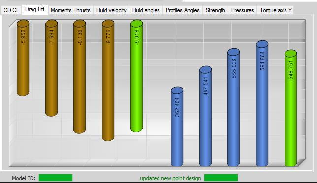
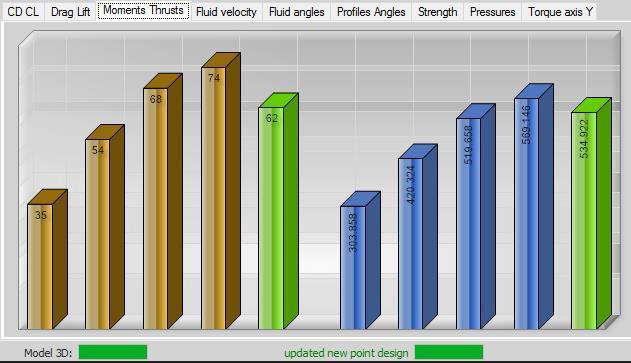
11
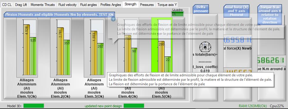
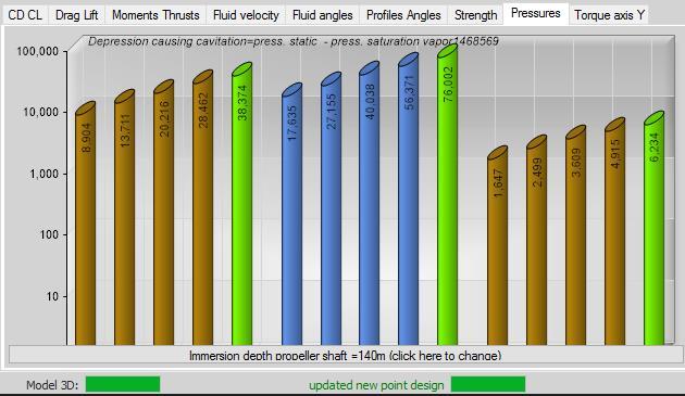
12


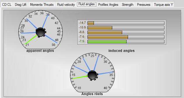
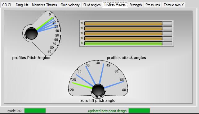
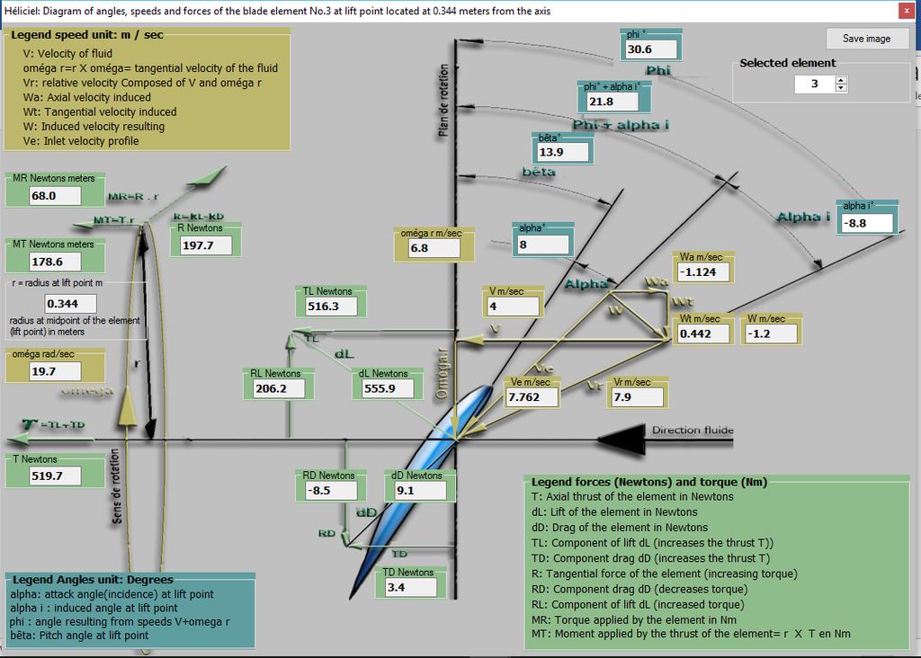
13 6.1 Force, Velocity and Angle Diagrams for Each Element Heliciel is also capable of drawing velocity diagrams with full detailed knowledge of symbols and values of physical quantities. These diagrams are self-explanatory for the students of fluid mechanics. Go to Edit and select diagram of Forces, Velocities and angles.
14 These Diagrams are shown For Element 1, Element 2, Element 3, Element 4 and Element 5 respectively.
15

16

17 Results & Calculation Notes Summary For the summary of calcultaions performed for the 5 individual elements of blade, click an icon higlighted mentioning Calculation notes. A new window will apear representing the summary of all calculations.
Research and Design working characteristics of orthogonal turbine Nguyen Quoc Tuan (1), Chu Dinh Do (2), Quach Thi Son (2)
, Chu Dinh Do (2), Quach Thi Son (2)") GSJ: VOLUME 6, ISSUE 6, JUNE 018 116 Research and Design working characteristics of orthogonal turbine Nguyen Quoc Tuan (1), Chu Dinh Do (), Quach Thi Son () (1) Institute for hydro power and renewable
GSJ: VOLUME 6, ISSUE 6, JUNE 018 116 Research and Design working characteristics of orthogonal turbine Nguyen Quoc Tuan (1), Chu Dinh Do (), Quach Thi Son () (1) Institute for hydro power and renewable
Introduction to CFX. Workshop 2. Transonic Flow Over a NACA 0012 Airfoil. WS2-1. ANSYS, Inc. Proprietary 2009 ANSYS, Inc. All rights reserved.
 Workshop 2 Transonic Flow Over a NACA 0012 Airfoil. Introduction to CFX WS2-1 Goals The purpose of this tutorial is to introduce the user to modelling flow in high speed external aerodynamic applications.
Using Multiple Rotating Reference Frames
 Tutorial 9. Using Multiple Rotating Reference Frames Introduction Many engineering problems involve rotating flow domains. One example is the centrifugal blower unit that is typically used in automotive
Compressible Flow in a Nozzle
 SPC 407 Supersonic & Hypersonic Fluid Dynamics Ansys Fluent Tutorial 1 Compressible Flow in a Nozzle Ahmed M Nagib Elmekawy, PhD, P.E. Problem Specification Consider air flowing at high-speed through a
Using Multiple Rotating Reference Frames
 Tutorial 10. Using Multiple Rotating Reference Frames Introduction Many engineering problems involve rotating flow domains. One example is the centrifugal blower unit that is typically used in automotive
Introduction to ANSYS CFX
 Workshop 03 Fluid flow around the NACA0012 Airfoil 16.0 Release Introduction to ANSYS CFX 2015 ANSYS, Inc. March 13, 2015 1 Release 16.0 Workshop Description: The flow simulated is an external aerodynamics
CFD Simulations of Flow over Airfoils:
 CFD Simulations of Flow over Airfoils: An Analysis of Wind Turbine Blade Aerodynamics By: John Hamilla, Mechanical Engineering Advisor: Maria-Isabel Carnasciali, Ph.D. Abstract Wind turbines are rapidly
Potsdam Propeller Test Case (PPTC)
") Second International Symposium on Marine Propulsors smp 11, Hamburg, Germany, June 2011 Workshop: Propeller performance Potsdam Propeller Test Case (PPTC) Olof Klerebrant Klasson 1, Tobias Huuva 2 1 Core
Second International Symposium on Marine Propulsors smp 11, Hamburg, Germany, June 2011 Workshop: Propeller performance Potsdam Propeller Test Case (PPTC) Olof Klerebrant Klasson 1, Tobias Huuva 2 1 Core
Simulation of Turbulent Flow around an Airfoil
 1. Purpose Simulation of Turbulent Flow around an Airfoil ENGR:2510 Mechanics of Fluids and Transfer Processes CFD Lab 2 (ANSYS 17.1; Last Updated: Nov. 7, 2016) By Timur Dogan, Michael Conger, Andrew
Simulation of Turbulent Flow around an Airfoil
 Simulation of Turbulent Flow around an Airfoil ENGR:2510 Mechanics of Fluids and Transfer Processes CFD Pre-Lab 2 (ANSYS 17.1; Last Updated: Nov. 7, 2016) By Timur Dogan, Michael Conger, Andrew Opyd, Dong-Hwan
Using the Eulerian Multiphase Model for Granular Flow
 Tutorial 21. Using the Eulerian Multiphase Model for Granular Flow Introduction Mixing tanks are used to maintain solid particles or droplets of heavy fluids in suspension. Mixing may be required to enhance
Axial Channel Water Jacket Cooling
 28 November 2017 Motor-CAD Software Tutorial: Axial Channel Water Jacket Cooling Contents 1. Description... 1 2. Setting up the housing and axial channels... 2 3. Setting the water jacket fluid and flow
Modeling Evaporating Liquid Spray
 Tutorial 17. Modeling Evaporating Liquid Spray Introduction In this tutorial, the air-blast atomizer model in ANSYS FLUENT is used to predict the behavior of an evaporating methanol spray. Initially, the
Wind tunnel experiments on a rotor model in yaw
 Nord-Jan ermeer Faculty of Civil Engineering and Geosciences Stevinweg 8 CN Delft The Netherlands Tel: + 78 Fax: + 78 7 E-mail: n.vermeer@ct.tudelft.nl http://www.ct.tudelft.nl/windenergy/ivwhome.htm The
equivalent stress to the yield stess.
 Example 10.2-1 [Ansys Workbench/Thermal Stress and User Defined Result] A 50m long deck sitting on superstructures that sit on top of substructures is modeled by a box shape of size 20 x 5 x 50 m 3. It
FEMLAB Exercise 1 for ChE366
 FEMLAB Exercise 1 for ChE366 Problem statement Consider a spherical particle of radius r s moving with constant velocity U in an infinitely long cylinder of radius R that contains a Newtonian fluid. Let
Tutorial 1: Welded Frame - Problem Description
 Tutorial 1: Welded Frame - Problem Description Introduction In this first tutorial, we will analyse a simple frame: firstly as a welded frame, and secondly as a pin jointed truss. In each case, we will
Flow Sim. Chapter 16. Airplane. A. Add-In. Step 1. If necessary, open your ASSEMBLY file.
 Chapter 16 A. Add-In. Step 1. If necessary, open your ASSEMBLY file. Airplane Flow Sim Step 2. Click Tools Menu > Add-Ins. Step 3. In the dialog box, scroll down to Flow Simulation and place a check in
Optimization of Hydraulic Fluid Parameters in Automotive Torque Converters
 Optimization of Hydraulic Fluid Parameters in Automotive Torque Converters S. Venkateswaran, and C. Mallika Parveen Abstract The fluid flow and the properties of the hydraulic fluid inside a torque converter
Solved with COMSOL Multiphysics 4.0a. COPYRIGHT 2010 COMSOL AB.
 Journal Bearing Introduction Journal bearings are used to carry radial loads, for example, to support a rotating shaft. A simple journal bearing consists of two rigid cylinders. The outer cylinder (bearing)
Verification and Validation of Turbulent Flow around a Clark-Y Airfoil
 Verification and Validation of Turbulent Flow around a Clark-Y Airfoil 1. Purpose 58:160 Intermediate Mechanics of Fluids CFD LAB 2 By Tao Xing and Fred Stern IIHR-Hydroscience & Engineering The University
An Introduction to SolidWorks Flow Simulation 2010
 An Introduction to SolidWorks Flow Simulation 2010 John E. Matsson, Ph.D. SDC PUBLICATIONS www.sdcpublications.com Schroff Development Corporation Chapter 2 Flat Plate Boundary Layer Objectives Creating
The viscous forces on the cylinder are proportional to the gradient of the velocity field at the
 Fluid Dynamics Models : Flow Past a Cylinder Flow Past a Cylinder Introduction The flow of fluid behind a blunt body such as an automobile is difficult to compute due to the unsteady flows. The wake behind
Simulation of Turbulent Flow over the Ahmed Body
 1 Simulation of Turbulent Flow over the Ahmed Body ME:5160 Intermediate Mechanics of Fluids CFD LAB 4 (ANSYS 18.1; Last Updated: Aug. 18, 2016) By Timur Dogan, Michael Conger, Dong-Hwan Kim, Maysam Mousaviraad,
Steady-State and Transient Thermal Analysis of a Circuit Board
 Steady-State and Transient Thermal Analysis of a Circuit Board Problem Description The circuit board shown below includes three chips that produce heat during normal operation. One chip stays energized
Multibody Model for Planetary Gearbox of 500 kw Wind Turbine
 Downloaded from orbit.dtu.dk on: Oct 19, 2018 Multibody Model for Planetary Gearbox of 500 kw Wind Turbine Jørgensen, Martin Felix Publication date: 2013 Link back to DTU Orbit Citation (APA): Jørgensen,
Simulation of Flow Development in a Pipe
 Tutorial 4. Simulation of Flow Development in a Pipe Introduction The purpose of this tutorial is to illustrate the setup and solution of a 3D turbulent fluid flow in a pipe. The pipe networks are common
0 Graphical Analysis Use of Excel
 Lab 0 Graphical Analysis Use of Excel What You Need To Know: This lab is to familiarize you with the graphing ability of excels. You will be plotting data set, curve fitting and using error bars on the
MASTA 9.0 Release Notes
 November 2018 2018 Smart Manufacturing Technology Ltd. Commercial in Confidence Page 1 of 33 MASTA 9.0 Contents and Summary See next section for additional details The 9.0 release of MASTA contains all
Use 6DOF solver to calculate motion of the moving body. Create TIFF files for graphic visualization of the solution.
 Introduction The purpose of this tutorial is to provide guidelines and recommendations for setting up and solving a moving deforming mesh (MDM) case along with the six degree of freedom (6DOF) solver and
Modeling External Compressible Flow
 Tutorial 3. Modeling External Compressible Flow Introduction The purpose of this tutorial is to compute the turbulent flow past a transonic airfoil at a nonzero angle of attack. You will use the Spalart-Allmaras
ANALYSIS OF BOX CULVERT - COST OPTIMIZATION FOR DIFFERENT ASPECT RATIOS OF CELL
 ANALYSIS OF BOX CULVERT - COST OPTIMIZATION FOR DIFFERENT ASPECT RATIOS OF CELL M.G. Kalyanshetti 1, S.A. Gosavi 2 1 Assistant professor, Civil Engineering Department, Walchand Institute of Technology,
Non-Newtonian Transitional Flow in an Eccentric Annulus
 Tutorial 8. Non-Newtonian Transitional Flow in an Eccentric Annulus Introduction The purpose of this tutorial is to illustrate the setup and solution of a 3D, turbulent flow of a non-newtonian fluid. Turbulent
Appendix: To be performed during the lab session
 Appendix: To be performed during the lab session Flow over a Cylinder Two Dimensional Case Using ANSYS Workbench Simple Mesh Latest revision: September 18, 2014 The primary objective of this Tutorial is
Numerische Untersuchungen von Windkraftanlagen: Leistung, Wake und Steuerungsstrategien
 Fachtagung Lasermethoden in der Strömungsmesstechnik 8. 10. September 2015, Dresden Numerische Untersuchungen von Windkraftanlagen: Leistung, Wake und Steuerungsstrategien Numerical Investigations of Wind
Modeling Evaporating Liquid Spray
 Tutorial 16. Modeling Evaporating Liquid Spray Introduction In this tutorial, FLUENT s air-blast atomizer model is used to predict the behavior of an evaporating methanol spray. Initially, the air flow
AIR LOAD CALCULATION FOR ISTANBUL TECHNICAL UNIVERSITY (ITU), LIGHT COMMERCIAL HELICOPTER (LCH) DESIGN ABSTRACT
, LIGHT COMMERCIAL HELICOPTER (LCH) DESIGN ABSTRACT") AIR LOAD CALCULATION FOR ISTANBUL TECHNICAL UNIVERSITY (ITU), LIGHT COMMERCIAL HELICOPTER (LCH) DESIGN Adeel Khalid *, Daniel P. Schrage + School of Aerospace Engineering, Georgia Institute of Technology
AIR LOAD CALCULATION FOR ISTANBUL TECHNICAL UNIVERSITY (ITU), LIGHT COMMERCIAL HELICOPTER (LCH) DESIGN Adeel Khalid *, Daniel P. Schrage + School of Aerospace Engineering, Georgia Institute of Technology
A Design Tecnique for a High Quantity Axial Flow Pump Impeller using Voznisenki Mean Camber Line Design Method
 Student Research Paper Conference Vol-2, No-36, July 2015 A Design Tecnique for a High Quantity Axial Flow Pump Impeller using Voznisenki Mean Camber Line Design Method M.Hamza Khan Department of Aeronautics
Putting the Spin in CFD
 w h i t e p a p e r Putting the Spin in CFD insight S U M MARY Engineers who design equipment with rotating components need to analyze and understand the behavior of those components if they want to improve
Express Introductory Training in ANSYS Fluent Workshop 04 Fluid Flow Around the NACA0012 Airfoil
 Express Introductory Training in ANSYS Fluent Workshop 04 Fluid Flow Around the NACA0012 Airfoil Dimitrios Sofialidis Technical Manager, SimTec Ltd. Mechanical Engineer, PhD PRACE Autumn School 2013 -
Using a Single Rotating Reference Frame
 Tutorial 9. Using a Single Rotating Reference Frame Introduction This tutorial considers the flow within a 2D, axisymmetric, co-rotating disk cavity system. Understanding the behavior of such flows is
SolidWorks Flow Simulation 2014
 An Introduction to SolidWorks Flow Simulation 2014 John E. Matsson, Ph.D. SDC PUBLICATIONS Better Textbooks. Lower Prices. www.sdcpublications.com Powered by TCPDF (www.tcpdf.org) Visit the following websites
Design and Development of Unmanned Tilt T-Tri Rotor Aerial Vehicle
 Design and Development of Unmanned Tilt T-Tri Rotor Aerial Vehicle K. Senthil Kumar, Mohammad Rasheed, and T.Anand Abstract Helicopter offers the capability of hover, slow forward movement, vertical take-off
[1] involuteσ(spur and Helical Gear Design)
![[1] involuteσ(spur and Helical Gear Design)](/thumbs/82/86018000.jpg "[1] involuteσ(spur and Helical Gear Design)") [1] involuteσ(spur and Helical Gear Design) 1.3 Software Content 1.3.1 Icon Button There are 12 icon buttons: [Dimension], [Tooth Form], [Accuracy], [Strength], [Sliding Graph], [Hertz Stress Graph], [FEM],
[1] involuteσ(spur and Helical Gear Design) 1.3 Software Content 1.3.1 Icon Button There are 12 icon buttons: [Dimension], [Tooth Form], [Accuracy], [Strength], [Sliding Graph], [Hertz Stress Graph], [FEM],
v Data Visualization SMS 12.3 Tutorial Prerequisites Requirements Time Objectives Learn how to import, manipulate, and view solution data.
 v. 12.3 SMS 12.3 Tutorial Objectives Learn how to import, manipulate, and view solution data. Prerequisites None Requirements GIS Module Map Module Time 30 60 minutes Page 1 of 16 Aquaveo 2017 1 Introduction...
SolidWorks Motion Study Tutorial
 SolidWorks Motion Study Tutorial By: Mohamed Hakeem Mohamed Nizar Mechanical Engineering Student- May 2015 South Dakota School of Mines & Technology August 2013 Getting Started This tutorial is for you
Analysis of an airfoil
 UNDERGRADUATE RESEARCH FALL 2010 Analysis of an airfoil using Computational Fluid Dynamics Tanveer Chandok 12/17/2010 Independent research thesis at the Georgia Institute of Technology under the supervision
This tutorial illustrates how to set up and solve a problem involving solidification. This tutorial will demonstrate how to do the following:
 Tutorial 22. Modeling Solidification Introduction This tutorial illustrates how to set up and solve a problem involving solidification. This tutorial will demonstrate how to do the following: Define a
µ = Pa s m 3 The Reynolds number based on hydraulic diameter, D h = 2W h/(w + h) = 3.2 mm for the main inlet duct is = 359
 = 3.2 mm for the main inlet duct is = 359") Laminar Mixer Tutorial for STAR-CCM+ ME 448/548 March 30, 2014 Gerald Recktenwald gerry@pdx.edu 1 Overview Imagine that you are part of a team developing a medical diagnostic device. The device has a millimeter
Laminar Mixer Tutorial for STAR-CCM+ ME 448/548 March 30, 2014 Gerald Recktenwald gerry@pdx.edu 1 Overview Imagine that you are part of a team developing a medical diagnostic device. The device has a millimeter
Express Introductory Training in ANSYS Fluent Workshop 06 Using Moving Reference Frames and Sliding Meshes
 Express Introductory Training in ANSYS Fluent Workshop 06 Using Moving Reference Frames and Sliding Meshes Dimitrios Sofialidis Technical Manager, SimTec Ltd. Mechanical Engineer, PhD PRACE Autumn School
Verification and Validation of Turbulent Flow around a Clark-Y Airfoil
 1 Verification and Validation of Turbulent Flow around a Clark-Y Airfoil 1. Purpose ME:5160 Intermediate Mechanics of Fluids CFD LAB 2 (ANSYS 19.1; Last Updated: Aug. 7, 2018) By Timur Dogan, Michael Conger,
November c Fluent Inc. November 8,
 MIXSIM 2.1 Tutorial November 2006 c Fluent Inc. November 8, 2006 1 Copyright c 2006 by Fluent Inc. All Rights Reserved. No part of this document may be reproduced or otherwise used in any form without
CHAPTER 8 FINITE ELEMENT ANALYSIS
 If you have any questions about this tutorial, feel free to contact Wenjin Tao (w.tao@mst.edu). CHAPTER 8 FINITE ELEMENT ANALYSIS Finite Element Analysis (FEA) is a practical application of the Finite
CFD Study of a Darreous Vertical Axis Wind Turbine
 CFD Study of a Darreous Vertical Axis Wind Turbine Md Nahid Pervez a and Wael Mokhtar b a Graduate Assistant b PhD. Assistant Professor Grand Valley State University, Grand Rapids, MI 49504 E-mail:, mokhtarw@gvsu.edu
Supersonic Flow Over a Wedge
 SPC 407 Supersonic & Hypersonic Fluid Dynamics Ansys Fluent Tutorial 2 Supersonic Flow Over a Wedge Ahmed M Nagib Elmekawy, PhD, P.E. Problem Specification A uniform supersonic stream encounters a wedge
A05 Steel Catenary Riser Systems
 A05 Steel Catenary Riser Systems Introduction This example contains three examples of steel catenary risers (SCRs). These are: Catenary with Spar Catenary with SemiSub Lazy Wave with FPSO The example also
Data Visualization SURFACE WATER MODELING SYSTEM. 1 Introduction. 2 Data sets. 3 Open the Geometry and Solution Files
 SURFACE WATER MODELING SYSTEM Data Visualization 1 Introduction It is useful to view the geospatial data utilized as input and generated as solutions in the process of numerical analysis. It is also helpful
How to Enter and Analyze a Wing
 How to Enter and Analyze a Wing Entering the Wing The Stallion 3-D built-in geometry creation tool can be used to model wings and bodies of revolution. In this example, a simple rectangular wing is modeled
CFD Post-Processing of Rampressor Rotor Compressor
 Gas Turbine Industrial Fellowship Program 2006 CFD Post-Processing of Rampressor Rotor Compressor Curtis Memory, Brigham Young niversity Ramgen Power Systems Mentor: Rob Steele I. Introduction Recent movements
VISIMIX TURBULENT. TANK WITH DISK TURBINE IMPELLER. POWER. SHEAR. MIXING TIME.
 VISIMIX TURBULENT. TANK WITH DISK TURBINE IMPELLER. POWER. SHEAR. MIXING TIME. This example shows how to calculate main hydrodynamic parameters - flow velocities, vortex formation, local values of turbulent
v SMS 11.1 Tutorial Data Visualization Requirements Map Module Mesh Module Time minutes Prerequisites None Objectives
 v. 11.1 SMS 11.1 Tutorial Data Visualization Objectives It is useful to view the geospatial data utilized as input and generated as solutions in the process of numerical analysis. It is also helpful to
Version 1.1. COPYRIGHT 1999 Tufts University and Vernier Software. ISBN (Windows) ISBN (Macintosh)
 ISBN (Macintosh)") Logger Pro Tutorials Version 1.1 COPYRIGHT 1999 Tufts University and Vernier Software ISBN 0-918731-92-5 (Windows) ISBN 0-918731-91-7 (Macintosh) Distributed by Vernier Software 8565 S.W. Beaverton-Hillsdale
Logger Pro Tutorials Version 1.1 COPYRIGHT 1999 Tufts University and Vernier Software ISBN 0-918731-92-5 (Windows) ISBN 0-918731-91-7 (Macintosh) Distributed by Vernier Software 8565 S.W. Beaverton-Hillsdale
First Steps - Ball Valve Design
 COSMOSFloWorks 2004 Tutorial 1 First Steps - Ball Valve Design This First Steps tutorial covers the flow of water through a ball valve assembly before and after some design changes. The objective is to
ANSYS AIM Tutorial Steady Flow Past a Cylinder
 ANSYS AIM Tutorial Steady Flow Past a Cylinder Author(s): Sebastian Vecchi, ANSYS Created using ANSYS AIM 18.1 Problem Specification Pre-Analysis & Start Up Solution Domain Boundary Conditions Start-Up
IRIS POWER HYDRO. Machine Condition Monitoring System for Hydro Generators
 IRIS POWER HYDRO Machine Condition Monitoring System for Hydro Generators PREDICTIVE MAINTENANCE On-line monitoring system installed in power production plants ensures continuous monitoring of exploitation
the lines of the solution obtained in for the twodimensional for an incompressible secondorder
 Flow of an Incompressible Second-Order Fluid past a Body of Revolution M.S.Saroa Department of Mathematics, M.M.E.C., Maharishi Markandeshwar University, Mullana (Ambala), Haryana, India ABSTRACT- The
Flow Sim. Chapter 14 P-51. A. Set Up. B. Create Flow Simulation Project. Step 1. Click Flow Simulation. SolidWorks 10 Flow Sim P-51 Page 14-1
 Chapter 14 A. Set Up. P-51 Flow Sim Step 1. If necessary, open your ASSEMBLY file. Step 2. Click Tools Menu > Add-Ins. Step 3. In the dialog box, scroll down to Flow Simulation and place a check in the
Research Article A Computational Investigation of Unsteady Aerodynamics of Insect-Inspired Fixed Wing Micro Aerial Vehicle s 2D Airfoil
 Advances in Aerospace Engineering, Article ID 5449, 7 pages http://dx.doi.org/1.1155/214/5449 Research Article A Computational Investigation of Unsteady Aerodynamics of Insect-Inspired Fixed Wing Micro
Plotting Graphs. Error Bars
 E Plotting Graphs Construct your graphs in Excel using the method outlined in the Graphing and Error Analysis lab (in the Phys 124/144/130 laboratory manual). Always choose the x-y scatter plot. Number
DEMONSTRATION OF THE DESIGN OF A FIRST-STAGE AXIAL-FLOW COMPRESSOR BLADE USING SOLID MODELING THROUGH A CLASSROOM PROJECT
 DEMONSTRATION OF THE DESIGN OF A FIRST-STAGE AXIAL-FLOW COMPRESSOR BLADE USING SOLID MODELING THROUGH A CLASSROOM PROJECT Breon Williams, Brandon Howard, Xiaoqing Qian and Z.T. Deng, Alabama A&M University
Flow Sim. Chapter 16. Airplane. A. Enable Flow Simulation. Step 1. If necessary, open your ASSEMBLY file.
 Chapter 16 Airplane Flow Sim A. Enable Flow Simulation. Step 1. If necessary, open your ASSEMBLY file. Step 2. If necessary, turn on Flow Simulation, click the flyout of Options on the Standard toolbar
Presentation summary
 Nantes - 2014 Aérojoules project: Vertical axis Wind Turbine Blade Aerodynamic optimisation MICHAEL O CONNOR 1 Presentation summary I. Aérojoules project Aim of the study II. Understanding Blade aerodynamics
Section 10.1 Polar Coordinates
 Section 10.1 Polar Coordinates Up until now, we have always graphed using the rectangular coordinate system (also called the Cartesian coordinate system). In this section we will learn about another system,
Simulation of Turbulent Flow over the Ahmed Body
 Simulation of Turbulent Flow over the Ahmed Body 58:160 Intermediate Mechanics of Fluids CFD LAB 4 By Timur K. Dogan, Michael Conger, Maysam Mousaviraad, and Fred Stern IIHR-Hydroscience & Engineering
Math Section 4.2 Radians, Arc Length, and Area of a Sector
 Math 1330 - Section 4.2 Radians, Arc Length, and Area of a Sector The word trigonometry comes from two Greek roots, trigonon, meaning having three sides, and meter, meaning measure. We have already defined
RSPile. Tutorial 3 Grouped Pile Analysis. Pile Analysis Software. Grouped Pile Analysis
 RSPile Pile Analysis Software Tutorial 3 Grouped Pile Analysis Grouped Pile Analysis Introduction This tutorial will demonstrate how to model grouped piles under a cap. The finished product of this tutorial
USER MANUAL FOR THE PROGRAM FOIL 97. Copyright 1998,2001 Vacanti Yacht Design. All Rights Reserved. Purpose of the Program:
 USER MANUAL FOR THE PROGRAM FOIL 97 Copyright 1998,2001 Vacanti Yacht Design All Rights Reserved Purpose of the Program: The program FOIL was written to allow the development of new air or hydro-foil shapes
ANSYS AIM Tutorial Fluid Flow Through a Transition Duct
 ANSYS AIM Tutorial Fluid Flow Through a Transition Duct Author(s): Sebastian Vecchi, ANSYS Created using ANSYS AIM 18.1 Problem Specification Start Up Geometry Import Geometry Extracting Volume Suppress
and to the following students who assisted in the creation of the Fluid Dynamics tutorials:
 Fluid Dynamics CAx Tutorial: Channel Flow Basic Tutorial # 4 Deryl O. Snyder C. Greg Jensen Brigham Young University Provo, UT 84602 Special thanks to: PACE, Fluent, UGS Solutions, Altair Engineering;
SPC 307 Aerodynamics. Lecture 1. February 10, 2018
 SPC 307 Aerodynamics Lecture 1 February 10, 2018 Sep. 18, 2016 1 Course Materials drahmednagib.com 2 COURSE OUTLINE Introduction to Aerodynamics Review on the Fundamentals of Fluid Mechanics Euler and
Fluid Dynamics Software Lab. Flow past an airfoil
 Second Summer School on Embodied Intelligence Simulation and Modelling within Embodied Intelligence 27 June - 1 July 2011, Zürich, Switzerland Dr Asimina Kazakidi Foundation for Research and Technology
Riding Lawnmower with V-Belt Tutorial (Belt)
") Riding Lawnmower with V-Belt Tutorial (Belt) Copyright 2018 FunctionBay, Inc. All rights reserved. User and training documentation from FunctionBay, Inc. is subjected to the copyright laws of the Republic
Riding Lawnmower with V-Belt Tutorial (Belt) Copyright 2018 FunctionBay, Inc. All rights reserved. User and training documentation from FunctionBay, Inc. is subjected to the copyright laws of the Republic
ONE DIMENSIONAL (1D) SIMULATION TOOL: GT-POWER
 SIMULATION TOOL: GT-POWER") CHAPTER 4 ONE DIMENSIONAL (1D) SIMULATION TOOL: GT-POWER 4.1 INTRODUCTION Combustion analysis and optimization of any reciprocating internal combustion engines is too complex and intricate activity. It
CHAPTER 4 ONE DIMENSIONAL (1D) SIMULATION TOOL: GT-POWER 4.1 INTRODUCTION Combustion analysis and optimization of any reciprocating internal combustion engines is too complex and intricate activity. It
Optimization of an Axial Pump using CFturbo, PumpLinx & optislang
 13th Annual Weimar Optimization and Stochastic Days 2016 Conference for CAE-based parametric optimization, stochastic analysis and Robust Design Optimization Optimization of an Axial Pump using CFturbo,
DYNAMIC ANALYSIS OF A GENERATOR ON AN ELASTIC FOUNDATION
 DYNAMIC ANALYSIS OF A GENERATOR ON AN ELASTIC FOUNDATION 7 DYNAMIC ANALYSIS OF A GENERATOR ON AN ELASTIC FOUNDATION In this tutorial the influence of a vibrating source on its surrounding soil is studied.
Simulation and Validation of Turbulent Pipe Flows
 Simulation and Validation of Turbulent Pipe Flows ENGR:2510 Mechanics of Fluids and Transport Processes CFD LAB 1 (ANSYS 17.1; Last Updated: Oct. 10, 2016) By Timur Dogan, Michael Conger, Dong-Hwan Kim,
Application of Hydrodynamics and Dynamics Models for Efficient Operation of Modular Mini-AUVs in Shallow and Very-Shallow Waters
 Application of Hydrodynamics and Dynamics Models for Efficient Operation of Modular Mini-AUVs in Shallow and Very-Shallow Waters P. Ananthakrishnan Department of Ocean Engineering Florida Atlantic University
Flow Sim. Chapter 12. F1 Car. A. Enable Flow Simulation. Step 1. If necessary, open your ASSEMBLY file.
 Chapter 12 F1 Car Flow Sim A. Enable Flow Simulation. Step 1. If necessary, open your ASSEMBLY file. Step 2. If necessary, turn on Flow Simulation, click the flyout of Options on the Standard toolbar and
Tutorial 1. Introduction to Using FLUENT: Fluid Flow and Heat Transfer in a Mixing Elbow
 Tutorial 1. Introduction to Using FLUENT: Fluid Flow and Heat Transfer in a Mixing Elbow Introduction This tutorial illustrates the setup and solution of the two-dimensional turbulent fluid flow and heat
An Open Source Parametric Propeller Design Tool
 An Open Source Parametric Propeller Design Tool LTJG Kathryn P. D Epagnier, USN *, Hsin-Lung Chung *, Michael J. Stanway *, and Richard W. Kimball *+ Massachusetts Institute of Technology *, Woods Hole
1 General description
 1 General description OAD OAD was set up to develop and sell ADS, which stands for Aircraft Design Software. This software is dedicated to take you through nearly the entire aircraft design process for
FLOWING FLUIDS AND PRESSURE VARIATION
 Chapter 4 Pressure differences are (often) the forces that move fluids FLOWING FLUIDS AND PRESSURE VARIATION Fluid Mechanics, Spring Term 2011 e.g., pressure is low at the center of a hurricane. For your
Excel Spreadsheets and Graphs
 Excel Spreadsheets and Graphs Spreadsheets are useful for making tables and graphs and for doing repeated calculations on a set of data. A blank spreadsheet consists of a number of cells (just blank spaces
How do you roll? Fig. 1 - Capstone screen showing graph areas and menus
 How do you roll? Purpose: Observe and compare the motion of a cart rolling down hill versus a cart rolling up hill. Develop a mathematical model of the position versus time and velocity versus time for
Verification of Laminar and Validation of Turbulent Pipe Flows
 1 Verification of Laminar and Validation of Turbulent Pipe Flows 1. Purpose ME:5160 Intermediate Mechanics of Fluids CFD LAB 1 (ANSYS 18.1; Last Updated: Aug. 1, 2017) By Timur Dogan, Michael Conger, Dong-Hwan
Installing and Using Trackside Cameras Revised November 2008
 Installing and Using Trackside Cameras Revised November 2008 Trackside cameras are a useful and creative way to add visual interest to your route. Rather than just look out the windshield of the locomotive
Tutorial 7 Finite Element Groundwater Seepage. Steady state seepage analysis Groundwater analysis mode Slope stability analysis
 Tutorial 7 Finite Element Groundwater Seepage Steady state seepage analysis Groundwater analysis mode Slope stability analysis Introduction Within the Slide program, Slide has the capability to carry out
FLUID DYNAMICS ANALYSIS OF A COUNTER ROTATING DUCTED PROPELLER
 FLUID DYNAMICS ANALYSIS OF A COUNTER ROTATING DUCTED PROPELLER Chao Xu, Cees Bil, Sherman CP. Cheung School of Aerospace, Mechanical and Manufacturing Engineering, RMIT University Keywords: Twin counter-rotating
An introduction to WindTrax
 An introduction to WindTrax By Brian Crenna This article is intended to introduce you to the main features and application of WindTrax, a graphical simulation environment for predicting turbulent transport
You will be prompted to start video or register now, exit out of this pop up to continue to the program
 Aspen Plus Tutorial Start Menu -> All Programs -> Aspen Plus -> Aspen Plus V9 You will be prompted to start video or register now, exit out of this pop up to continue to the program If you want to start