equivalent stress to the yield stess.
|
|
|
- Willis Johnston
- 5 years ago
- Views:
Transcription
![Example 10.2-1 [Ansys Workbench/Thermal Stress and User Defined Result] A 50m long deck sitting on superstructures that sit on top of substructures is modeled by a box shape of size 20 x 5 x 50 m 3.](/docs-images/82/86839969/images/1-0.jpg "It is subjected to 80 o C at top surface and convection all lateral surfaces. The end surfaces are fixed.")
 When the yield stess varies with temperature by, obtain the ratio of the equivalent stress to the yield stess. Figure 10.2.")
![1-1 The model deck and typical bridge structure (Michigan Dept of Transportation) Solution. 1. Add Static Thermal Analysis [Geometry] 2. Sketching tab> create the section 3.](/docs-images/82/86839969/images/1-2.jpg "Modeling tab >Extrude > Generate [Model] 4. Click Steady-State Thermal analysis in Outline 5. Temperature > pick the top surface > Apply > enter the temperature 6.")
1 Example [Ansys Workbench/Thermal Stress and User Defined Result] A 50m long deck sitting on superstructures that sit on top of substructures is modeled by a box shape of size 20 x 5 x 50 m 3. It is subjected to 80 o C at top surface and convection all lateral surfaces. The end surfaces are fixed. The convection coefficient of air is given by 50 W/m 2 - o C and the ambient temperature is 20 o C. The material is Structural Steel. (a) Compute the thermal stress distribution. (b) When the yield stess varies with temperature by, obtain the ratio of the equivalent stress to the yield stess. Figure The model deck and typical bridge structure (Michigan Dept of Transportation) Solution. 1. Add Static Thermal Analysis [Geometry] 2. Sketching tab> create the section 3. Modeling tab >Extrude > Generate [Model] 4. Click Steady-State Thermal analysis in Outline 5. Temperature > pick the top surface > Apply > enter the temperature 6. Convection > pick all lateral surfaces > Apply > enter the film coefficient and bulk temperature 7. Click Solution in Outline 8. Thermal > Temperature and Total Heat Flux 9. Solve 10. Drag and drop Static Structural analysis on top of Solution cell. The Schematic Map appears as 11. Double click Model cell [Model] 12. Click Static Structural in Outline 13. Imported Load from thermal analysis solution has been added 14. Supports > Fixed Support > pick both end surfaces > Apply


 > enter Expression of Y(T) using BFE for")

2 15. Add Total Deformation and Equivalent Stress in Solution 16. Solve 17. The Equivalent Stress appears as 18. Click Solution in Outline > click Worksheet on top menu bar 19. Scroll down to BFE and right click >Create User Defined Result 20. BFE is the name for temperature in Ansys and appears in Outline 21. Right click > Rename > change it to Y(T) > enter Expression of Y(T) using BFE for temperature > change Identifier to YT > see the result of Y(T) 22. Right click Solution in Outline > Insert > User Defined Result > right click it and change the name to SMargin > In Details, enter Expression as SEQV/YT and Identifier = SMargin 23. See user defined SMargin as
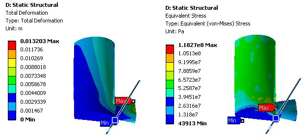
![Example 10.2.2-1 [CFX] A water tank has dimensions as shown below. The units are in MKS. The thickness is 0.1 m outward from the given dimensions.](/docs-images/82/86839969/images/3-0.jpg "(a) Create the tank by Revolve on XYPlane and the outlet pipe by Extrude on a new plane located at 10 m from XYPlane. Also, Blend with Radius = 0.5 m on the edge between two surfaces.")
 Use the CFX results to perform static stress analysis based on the pressure due to the flow. Figure 10.2.2-1 Water tank structure Solution. 1. Add Component System/Geometry [Geometry] 2.")
3 Example [CFX] A water tank has dimensions as shown below. The units are in MKS. The thickness is 0.1 m outward from the given dimensions. (a) Create the tank by Revolve on XYPlane and the outlet pipe by Extrude on a new plane located at 10 m from XYPlane. Also, Blend with Radius = 0.5 m on the edge between two surfaces. (b) Then, use Tools > Thin to create a thin structure. Use the outward thickness = 0.05 m. (c) Use Fill option to fill the tank for fluid. (d) Based on the geometry just created, perform CFX analysis. (e) Use the CFX results to perform static stress analysis based on the pressure due to the flow. Figure Water tank structure Solution. 1. Add Component System/Geometry [Geometry] 2. Sketching tab> create the closed section for the tank with Polyline 3. Modeling tab > Revolve > pick the axis of rotation / Apply > Generate 4. Click XYPlane > New Plane > Transformation 1 = Offset Z, FD1 = 10 m > Generate 5. Sketching tab > create the circle 6. Modeling tab >Extrude > Direction = Reversed > Depth = To Next > Generate 7. Tools > Thin > ctrl + pick both top and exit surfaces > Details/Selection Type=Faces to Remove / Direction=Outward / Thickness = 0.05 m > Generate 8. Assume that user forgot to add the round around the joint edge. Tree Outline/right click Thin feature just added > Insert > Fixed Radius > pick the joint edge/apply and enter the radius in Details > Generate
 12.")
![Drag and drop Fluid Flow (CFX) in Analysis Systems (not in Component Systems that does not have Geometry) on Geometry cell [Mesh] 13.](/docs-images/82/86839969/images/4-1.jpg "Generate mesh and see as (right now, just accept the default mesh).")
![User should try to use Inflation for mesh controls at inlet and outlet. See below the original and inflated meshes. [Setup] 14.](/docs-images/82/86839969/images/4-2.jpg "Double click Default Domain in Outline or right click and Edit a.")
4 9. Tools > Fill > Extraction Type = By Cavity > pick all three surfaces (the blended surface is not used in Fill) > Generate 10. Click Solid body created by Fill operation and see Fluid/Solid = Fluid 11. Select the Solid body> right click > Suppress (no need) 12. Drag and drop Fluid Flow (CFX) in Analysis Systems (not in Component Systems that does not have Geometry) on Geometry cell [Mesh] 13. Generate mesh and see as (right now, just accept the default mesh). User should try to use Inflation for mesh controls at inlet and outlet. See below the original and inflated meshes. [Setup] 14. Double click Default Domain in Outline or right click and Edit a. Basic Settings tab >Material = Water, Reference Pressure = 1 atm > OK 15. Boundary> enter a name inlet > OK b. Basic Settings tab Boundary Type = Inlet

5 Click Location > pick the top surface c. Boundary Details tab Mass and Momentum / Normal Speed = 1 m/s d. OK 16. Boundary> enter a name outlet > OK a. Basic Settings tab Boundary Type = Outlet Click Location > pick the end surface of the pipe b. Boundary Details tab Mass and Momentum > Option = Average Static Pressure, Relative Pressure = 1 atm c. OK 17. Double click Solution 18. Define Run dialog appears >Start Run> see the convergence plot as 19. Close the Solution window > back to Project [Results] 20. The initial wireframe may show much. Double click Wireframe in Outline a. Definition tab > drag the slider and make Edge Angle = 5 > Apply 21. Contour > OK (accept the default name) > double click the contour in Outline a. Geometry tab > Variable = Pressure > Apply
 > Apply 23.")
 > Apply b.")

6 b. Uncheck Wireframe in Outline (see above right) 22. Vector > OK for name > double click the vector in Outline a. Geometry tab > Variable = Velocity b. Symbol tab > Symbol Size = 2 (just adjust seeing the results) > Apply 23. Clip Plane > OK for name > double click the clip plane in Outline a. Geometry tab > Method = YZ Plane, X = 0 m, check Flip Normal (depends on your model orientation) > Apply b. Right click in Graphics window > Clip Scene > select the clip plane (see above right) 24. Streamline > OK for name > double click the streamline in Outline a. Uncheck all others in Outline not to display them excep the streamline b. Geometry tab > accept all defaults > Preview Seed Points > Apply

![Drag Fluid Flow/Solution and drop it on Structural Analysis/Setup [Static Structural / Model] 29.](/docs-images/82/86839969/images/7-1.jpg "Click Static Structural in Outline 30. Supports > Fixed Support > pick the bottom surface > Apply 31.")

7 25. Right click Geometry component > Duplicate 26. Double click the copy of Geometry a. Unsuppress solid body b. Suppress the fluid body 27. Drag and drop Static Structural analysis on Geometry cell of copied Geometry 28. Drag Fluid Flow/Solution and drop it on Structural Analysis/Setup [Static Structural / Model] 29. Click Static Structural in Outline 30. Supports > Fixed Support > pick the bottom surface > Apply 31. Right click Imported Load> Insert > Pressure a. In Details, select three inner surfaces for Geometry> Apply b. CFD Surface = Default Domain Default 32. Add Total Deformation and Equivalent Stress in Solution 33. Solve 34. Right click in Graphics window > View > Front 35. New Section Pane > draw a vertical line through the pipe > rotate the results
8
Tutorial to simulate a thermoelectric module with heatsink in ANSYS
 Tutorial to simulate a thermoelectric module with heatsink in ANSYS Few details can be found in the pictures attached. All the material properties can be found in Dr. Lee s book and on the web. Don t blindly
Appendix: To be performed during the lab session
 Appendix: To be performed during the lab session Flow over a Cylinder Two Dimensional Case Using ANSYS Workbench Simple Mesh Latest revision: September 18, 2014 The primary objective of this Tutorial is
Heat Exchanger Efficiency
 6 Heat Exchanger Efficiency Flow Simulation can be used to study the fluid flow and heat transfer for a wide variety of engineering equipment. In this example we use Flow Simulation to determine the efficiency
Simulation of Turbulent Flow around an Airfoil
 Simulation of Turbulent Flow around an Airfoil ENGR:2510 Mechanics of Fluids and Transfer Processes CFD Pre-Lab 2 (ANSYS 17.1; Last Updated: Nov. 7, 2016) By Timur Dogan, Michael Conger, Andrew Opyd, Dong-Hwan
Introduction to CFX. Workshop 2. Transonic Flow Over a NACA 0012 Airfoil. WS2-1. ANSYS, Inc. Proprietary 2009 ANSYS, Inc. All rights reserved.
 Workshop 2 Transonic Flow Over a NACA 0012 Airfoil. Introduction to CFX WS2-1 Goals The purpose of this tutorial is to introduce the user to modelling flow in high speed external aerodynamic applications.
Simulation of Turbulent Flow around an Airfoil
 1. Purpose Simulation of Turbulent Flow around an Airfoil ENGR:2510 Mechanics of Fluids and Transfer Processes CFD Lab 2 (ANSYS 17.1; Last Updated: Nov. 7, 2016) By Timur Dogan, Michael Conger, Andrew
Essay 5 Tutorial for a Three-Dimensional Heat Conduction Problem Using ANSYS
 Essay 5 Tutorial for a Three-Dimensional Heat Conduction Problem Using ANSYS 5.1 Introduction The problem selected to illustrate the use of ANSYS software for a three-dimensional steadystate heat conduction
Simulation of Laminar Pipe Flows
 Simulation of Laminar Pipe Flows 57:020 Mechanics of Fluids and Transport Processes CFD PRELAB 1 By Timur Dogan, Michael Conger, Maysam Mousaviraad, Tao Xing and Fred Stern IIHR-Hydroscience & Engineering
Basic Exercises Maxwell Link with ANSYS Mechanical. Link between ANSYS Maxwell 3D and ANSYS Mechanical
 Link between ANSYS Maxwell 3D and ANSYS Mechanical This exercise describes how to set up a Maxwell 3D Eddy Current project and then link the losses to ANSYS Mechanical for a thermal calculation 3D Geometry:
STEPS BY STEPS FOR THREE-DIMENSIONAL ANALYSIS USING ABAQUS STEADY-STATE HEAT TRANSFER ANALYSIS
 UNIVERSITI MALAYSIA PERLIS FACULTY OF ENGINEERING TECHNOLOGY DEPARTMENT OF MECHANICAL ENGINEERING TECHNOLOGY PDT348 FINITE ELEMENT ANALYSIS Semester II 2017/2018 STEPS BY STEPS FOR THREE-DIMENSIONAL ANALYSIS
ANSYS Workbench Guide
 ANSYS Workbench Guide Introduction This document serves as a step-by-step guide for conducting a Finite Element Analysis (FEA) using ANSYS Workbench. It will cover the use of the simulation package through
Solving FSI Applications Using ANSYS Mechanical and ANSYS Fluent
 Workshop Transient 1-way FSI Load Mapping using ACT Extension 15. 0 Release Solving FSI Applications Using ANSYS Mechanical and ANSYS Fluent 1 2014 ANSYS, Inc. Workshop Description: This example considers
First Steps - Conjugate Heat Transfer
 COSMOSFloWorks 2004 Tutorial 2 First Steps - Conjugate Heat Transfer This First Steps - Conjugate Heat Transfer tutorial covers the basic steps to set up a flow analysis problem including conduction heat
Coupled Analysis of FSI
 Coupled Analysis of FSI Qin Yin Fan Oct. 11, 2008 Important Key Words Fluid Structure Interface = FSI Computational Fluid Dynamics = CFD Pressure Displacement Analysis = PDA Thermal Stress Analysis = TSA
Simulation and Validation of Turbulent Pipe Flows
 Simulation and Validation of Turbulent Pipe Flows ENGR:2510 Mechanics of Fluids and Transport Processes CFD LAB 1 (ANSYS 17.1; Last Updated: Oct. 10, 2016) By Timur Dogan, Michael Conger, Dong-Hwan Kim,
Verification of Laminar and Validation of Turbulent Pipe Flows
 1 Verification of Laminar and Validation of Turbulent Pipe Flows 1. Purpose ME:5160 Intermediate Mechanics of Fluids CFD LAB 1 (ANSYS 18.1; Last Updated: Aug. 1, 2017) By Timur Dogan, Michael Conger, Dong-Hwan
Introduction to ANSYS CFX
 Workshop 03 Fluid flow around the NACA0012 Airfoil 16.0 Release Introduction to ANSYS CFX 2015 ANSYS, Inc. March 13, 2015 1 Release 16.0 Workshop Description: The flow simulated is an external aerodynamics
Workbench Tutorial Flow Over an Airfoil, Page 1 ANSYS Workbench Tutorial Flow Over an Airfoil
 Workbench Tutorial Flow Over an Airfoil, Page 1 ANSYS Workbench Tutorial Flow Over an Airfoil Authors: Scott Richards, Keith Martin, and John M. Cimbala, Penn State University Latest revision: 17 January
Verification and Validation of Turbulent Flow around a Clark-Y Airfoil
 1 Verification and Validation of Turbulent Flow around a Clark-Y Airfoil 1. Purpose ME:5160 Intermediate Mechanics of Fluids CFD LAB 2 (ANSYS 19.1; Last Updated: Aug. 7, 2018) By Timur Dogan, Michael Conger,
Modeling Evaporating Liquid Spray
 Tutorial 17. Modeling Evaporating Liquid Spray Introduction In this tutorial, the air-blast atomizer model in ANSYS FLUENT is used to predict the behavior of an evaporating methanol spray. Initially, the
Supersonic Flow Over a Wedge
 SPC 407 Supersonic & Hypersonic Fluid Dynamics Ansys Fluent Tutorial 2 Supersonic Flow Over a Wedge Ahmed M Nagib Elmekawy, PhD, P.E. Problem Specification A uniform supersonic stream encounters a wedge
An Introduction to SolidWorks Flow Simulation 2010
 An Introduction to SolidWorks Flow Simulation 2010 John E. Matsson, Ph.D. SDC PUBLICATIONS www.sdcpublications.com Schroff Development Corporation Chapter 2 Flat Plate Boundary Layer Objectives Creating
First Steps - Ball Valve Design
 COSMOSFloWorks 2004 Tutorial 1 First Steps - Ball Valve Design This First Steps tutorial covers the flow of water through a ball valve assembly before and after some design changes. The objective is to
SolidWorks Flow Simulation 2014
 An Introduction to SolidWorks Flow Simulation 2014 John E. Matsson, Ph.D. SDC PUBLICATIONS Better Textbooks. Lower Prices. www.sdcpublications.com Powered by TCPDF (www.tcpdf.org) Visit the following websites
This tutorial illustrates how to set up and solve a problem involving solidification. This tutorial will demonstrate how to do the following:
 Tutorial 22. Modeling Solidification Introduction This tutorial illustrates how to set up and solve a problem involving solidification. This tutorial will demonstrate how to do the following: Define a
Solid Conduction Tutorial
 SECTION 1 1 SECTION 1 The following is a list of files that will be needed for this tutorial. They can be found in the Solid_Conduction folder. Exhaust-hanger.tdf Exhaust-hanger.ntl 1.0.1 Overview The
Middle East Technical University Mechanical Engineering Department ME 413 Introduction to Finite Element Analysis Spring 2015 (Dr.
 Middle East Technical University Mechanical Engineering Department ME 413 Introduction to Finite Element Analysis Spring 2015 (Dr. Sert) COMSOL 1 Tutorial 2 Problem Definition Hot combustion gases of a
A B C D E. Settings Choose height, H, free stream velocity, U, and fluid (dynamic viscosity and density ) so that: Reynolds number
 so that: Reynolds number") Individual task Objective To derive the drag coefficient for a 2D object, defined as where D (N/m) is the aerodynamic drag force (per unit length in the third direction) acting on the object. The object
Individual task Objective To derive the drag coefficient for a 2D object, defined as where D (N/m) is the aerodynamic drag force (per unit length in the third direction) acting on the object. The object
Compressible Flow in a Nozzle
 SPC 407 Supersonic & Hypersonic Fluid Dynamics Ansys Fluent Tutorial 1 Compressible Flow in a Nozzle Ahmed M Nagib Elmekawy, PhD, P.E. Problem Specification Consider air flowing at high-speed through a
ANSYS AIM Tutorial Flow over an Ahmed Body
 Author(s): Sebastian Vecchi Created using ANSYS AIM 18.1 ANSYS AIM Tutorial Flow over an Ahmed Body Problem Specification Start Up Geometry Import Geometry Enclose Suppress Mesh Set Mesh Controls Generate
Modeling Evaporating Liquid Spray
 Tutorial 16. Modeling Evaporating Liquid Spray Introduction In this tutorial, FLUENT s air-blast atomizer model is used to predict the behavior of an evaporating methanol spray. Initially, the air flow
TryItNow! Step by Step Walkthrough: Spoiler Support
 TryItNow! Step by Step Walkthrough: Spoiler Support 1 2015 ANSYS, Inc. March 28, 2016 TryItNow! Step by Step Walkthrough: Spoiler Support ANSYS designed this TryItNow! experience to give you quick access
ANSYS AIM Tutorial Steady Flow Past a Cylinder
 ANSYS AIM Tutorial Steady Flow Past a Cylinder Author(s): Sebastian Vecchi, ANSYS Created using ANSYS AIM 18.1 Problem Specification Pre-Analysis & Start Up Solution Domain Boundary Conditions Start-Up
Steady-State and Transient Thermal Analysis of a Circuit Board
 Steady-State and Transient Thermal Analysis of a Circuit Board Problem Description The circuit board shown below includes three chips that produce heat during normal operation. One chip stays energized
µ = Pa s m 3 The Reynolds number based on hydraulic diameter, D h = 2W h/(w + h) = 3.2 mm for the main inlet duct is = 359
 = 3.2 mm for the main inlet duct is = 359") Laminar Mixer Tutorial for STAR-CCM+ ME 448/548 March 30, 2014 Gerald Recktenwald gerry@pdx.edu 1 Overview Imagine that you are part of a team developing a medical diagnostic device. The device has a millimeter
Laminar Mixer Tutorial for STAR-CCM+ ME 448/548 March 30, 2014 Gerald Recktenwald gerry@pdx.edu 1 Overview Imagine that you are part of a team developing a medical diagnostic device. The device has a millimeter
First Steps - Ball Valve Design
 COSMOSFloWorks 2004 Tutorial 1 First Steps - Ball Valve Design This First Steps tutorial covers the flow of water through a ball valve assembly before and after some design changes. The objective is to
Module D: Laminar Flow over a Flat Plate
 Module D: Laminar Flow over a Flat Plate Summary... Problem Statement Geometry and Mesh Creation Problem Setup Solution. Results Validation......... Mesh Refinement.. Summary This ANSYS FLUENT tutorial
New Capabilities in Project Hydra for Autodesk Simulation Mechanical
 New Capabilities in Project Hydra for Autodesk Simulation Mechanical Sualp Ozel, PE. Autodesk SM2447-L In this hands-on lab, we will go through several exercises and cover several new capabilities included
Introduction to ANSYS DesignModeler
 Lecture 5 Modeling 14. 5 Release Introduction to ANSYS DesignModeler 2012 ANSYS, Inc. November 20, 2012 1 Release 14.5 Preprocessing Workflow Geometry Creation OR Geometry Import Geometry Operations Meshing
Air Movement. Air Movement
 2018 Air Movement In this tutorial you will create an air flow using a supply vent on one side of a room and an open vent on the opposite side. This is a very simple PyroSim/FDS simulation, but illustrates
Simulation of Turbulent Flow over the Ahmed Body
 1 Simulation of Turbulent Flow over the Ahmed Body ME:5160 Intermediate Mechanics of Fluids CFD LAB 4 (ANSYS 18.1; Last Updated: Aug. 18, 2016) By Timur Dogan, Michael Conger, Dong-Hwan Kim, Maysam Mousaviraad,
Swapnil Nimse Project 1 Challenge #2
 Swapnil Nimse Project 1 Challenge #2 Project Overview: Using Ansys-Fluent, analyze dependency of the steady-state temperature at different parts of the system on the flow velocity at the inlet and buoyancy-driven
Wall thickness= Inlet: Prescribed mass flux. All lengths in meters kg/m, E Pa, 0.3,
 Problem description Problem 30: Analysis of fluid-structure interaction within a pipe constriction It is desired to analyze the flow and structural response within the following pipe constriction: 1 1
Visit the following websites to learn more about this book:
 Visit the following websites to learn more about this book: 6 Introduction to Finite Element Simulation Historically, finite element modeling tools were only capable of solving the simplest engineering
Flow Sim. Chapter 16. Airplane. A. Enable Flow Simulation. Step 1. If necessary, open your ASSEMBLY file.
 Chapter 16 Airplane Flow Sim A. Enable Flow Simulation. Step 1. If necessary, open your ASSEMBLY file. Step 2. If necessary, turn on Flow Simulation, click the flyout of Options on the Standard toolbar
ANSYS AIM Tutorial Fluid Flow Through a Transition Duct
 ANSYS AIM Tutorial Fluid Flow Through a Transition Duct Author(s): Sebastian Vecchi, ANSYS Created using ANSYS AIM 18.1 Problem Specification Start Up Geometry Import Geometry Extracting Volume Suppress
Simulation of Flow Development in a Pipe
 Tutorial 4. Simulation of Flow Development in a Pipe Introduction The purpose of this tutorial is to illustrate the setup and solution of a 3D turbulent fluid flow in a pipe. The pipe networks are common
Using Multiple Rotating Reference Frames
 Tutorial 10. Using Multiple Rotating Reference Frames Introduction Many engineering problems involve rotating flow domains. One example is the centrifugal blower unit that is typically used in automotive
Free Convection Cookbook for StarCCM+
 ME 448/548 February 28, 2012 Free Convection Cookbook for StarCCM+ Gerald Recktenwald gerry@me.pdx.edu 1 Overview Figure 1 depicts a two-dimensional fluid domain bounded by a cylinder of diameter D. Inside
Module 1.7W: Point Loading of a 3D Cantilever Beam
 Module 1.7W: Point Loading of a 3D Cantilever Beam Table of Contents Page Number Problem Description 2 Theory 2 Workbench Analysis System 4 Engineering Data 5 Geometry 6 Model 11 Setup 13 Solution 14 Results
Tutorial 2. Modeling Periodic Flow and Heat Transfer
 Tutorial 2. Modeling Periodic Flow and Heat Transfer Introduction: Many industrial applications, such as steam generation in a boiler or air cooling in the coil of an air conditioner, can be modeled as
3 AXIS STANDARD CAD. BobCAD-CAM Version 28 Training Workbook 3 Axis Standard CAD
 3 AXIS STANDARD CAD This tutorial explains how to create the CAD model for the Mill 3 Axis Standard demonstration file. The design process includes using the Shape Library and other wireframe functions
Problem description. Problem 65: Free convection in a lightbulb. Filament (Tungsten): Globe (Glass): = FSI boundary. Gas (Argon):
: Globe (Glass): = FSI boundary. Gas (Argon):") Problem description This tutorial demonstrates the use of ADINA for analyzing the fluid flow and heat transfer in a lightbulb using the Thermal Fluid-Structure Interaction (TFSI) features of ADINA. The
Problem description This tutorial demonstrates the use of ADINA for analyzing the fluid flow and heat transfer in a lightbulb using the Thermal Fluid-Structure Interaction (TFSI) features of ADINA. The
Middle East Technical University Mechanical Engineering Department ME 485 CFD with Finite Volume Method Fall 2017 (Dr. Sert)
") Middle East Technical University Mechanical Engineering Department ME 485 CFD with Finite Volume Method Fall 2017 (Dr. Sert) ANSYS Fluent Tutorial Developing Laminar Flow in a 2D Channel 1 How to use This
Middle East Technical University Mechanical Engineering Department ME 485 CFD with Finite Volume Method Fall 2017 (Dr. Sert) ANSYS Fluent Tutorial Developing Laminar Flow in a 2D Channel 1 How to use This
2. MODELING A MIXING ELBOW (2-D)
") MODELING A MIXING ELBOW (2-D) 2. MODELING A MIXING ELBOW (2-D) In this tutorial, you will use GAMBIT to create the geometry for a mixing elbow and then generate a mesh. The mixing elbow configuration is
MODELING A MIXING ELBOW (2-D) 2. MODELING A MIXING ELBOW (2-D) In this tutorial, you will use GAMBIT to create the geometry for a mixing elbow and then generate a mesh. The mixing elbow configuration is
Tutorial: Simulating a 3D Check Valve Using Dynamic Mesh 6DOF Model And Diffusion Smoothing
 Tutorial: Simulating a 3D Check Valve Using Dynamic Mesh 6DOF Model And Diffusion Smoothing Introduction The purpose of this tutorial is to demonstrate how to simulate a ball check valve with small displacement
Practice to Informatics for Energy and Environment
 Practice to Informatics for Energy and Environment Part 3: Finite Elemente Method Example 1: 2-D Domain with Heat Conduction Tutorial by Cornell University https://confluence.cornell.edu/display/simulation/ansys+-+2d+steady+conduction
Problem description. The figure shows a disc braking system.
 Problem description Problem 34: Thermo-mechanical coupling analysis of a disc braking system The figure shows a disc braking system. Applied pressure Piston Brake pad Brake disc Fixed plate Initially,
Module 4A: Creating the 3D Model of Right and Oblique Pyramids
 Inventor (5) Module 4A: 4A- 1 Module 4A: Creating the 3D Model of Right and Oblique Pyramids In Module 4A, we will learn how to create 3D solid models of right-axis and oblique-axis pyramid (regular or
Workbench Tutorial Minor Losses, Page 1 Tutorial Minor Losses using Pointwise and FLUENT
 Workbench Tutorial Minor Losses, Page 1 Tutorial Minor Losses using Pointwise and FLUENT Introduction This tutorial provides instructions for meshing two internal flows. Pointwise software will be used
Heat Transfer Analysis of a Pipe
 LESSON 25 Heat Transfer Analysis of a Pipe 3 Fluid 800 Ambient Temperture Temperture, C 800 500 2 Dia Fluid Ambient 10 20 30 40 Time, s Objectives: Transient Heat Transfer Analysis Model Convection, Conduction
ANSYS AIM Tutorial Turbulent Flow Over a Backward Facing Step
 ANSYS AIM Tutorial Turbulent Flow Over a Backward Facing Step Author(s): Sebastian Vecchi, ANSYS Created using ANSYS AIM 18.1 Problem Specification Pre-Analysis & Start Up Governing Equation Start-Up Geometry
Tutorial: Hydrodynamics of Bubble Column Reactors
 Tutorial: Introduction The purpose of this tutorial is to provide guidelines and recommendations for solving a gas-liquid bubble column problem using the multiphase mixture model, including advice on solver
Fully-Coupled Thermo-Mechanical Analysis
 Fully-Coupled Thermo-Mechanical Analysis Type of solver: ABAQUS CAE/Standard Adapted from: ABAQUS Example Problems Manual Extrusion of a Cylindrical Aluminium Bar with Frictional Heat Generation Problem
Abaqus/CAE Heat Transfer Tutorial
 Abaqus/CAE Heat Transfer Tutorial Problem Description The thin L shaped steel part shown above (lengths in meters) is exposed to a temperature of 20 o C on the two surfaces of the inner corner, and 120
CFD Simulation of a dry Scroll Vacuum Pump including Leakage Flows
 CFD Simulation of a dry Scroll Vacuum Pump including Leakage Flows Jan Hesse, Rainer Andres CFX Berlin Software GmbH, Berlin, Germany 1 Introduction Numerical simulation results of a dry scroll vacuum
Tutorial 2: Particles convected with the flow along a curved pipe.
 Tutorial 2: Particles convected with the flow along a curved pipe. Part 1: Creating an elbow In part 1 of this tutorial, you will create a model of a 90 elbow featuring a long horizontal inlet and a short
Non-Newtonian Transitional Flow in an Eccentric Annulus
 Tutorial 8. Non-Newtonian Transitional Flow in an Eccentric Annulus Introduction The purpose of this tutorial is to illustrate the setup and solution of a 3D, turbulent flow of a non-newtonian fluid. Turbulent
Ryian Hunter MAE 598
 Setup: The initial geometry was produced using the engineering schematics provided in the project assignment document using the ANSYS DesignModeler application taking advantage of system symmetry. Fig.
Modeling a Gear Standard Tools, Surface Tools Solid Tool View, Trackball, Show-Hide Snaps Window 1-1
 Modeling a Gear This tutorial describes how to create a toothed gear. It combines using wireframe, solid, and surface modeling together to create a part. The model was created in standard units. To begin,
Co-Simulation von Flownex und ANSYS CFX am Beispiel einer Verdrängermaschine
 Co-Simulation von Flownex und ANSYS CFX am Beispiel einer Verdrängermaschine Benoit Bosc-Bierne, Dr. Andreas Spille-Kohoff, Farai Hetze CFX Berlin Software GmbH, Berlin Contents Positive displacement compressors
Air flows around a pipe containing hot steam, as shown: Air 293 K
 Problem description Air flows around a pipe containing hot steam, as shown: x y z Air 293 K Fan: P 1.0 10 10 Q 2 4 2 Steel Steam (ASME) 101 KPa 430 K The air inlet boundary condition is given as a function
STAR-CCM+: Wind loading on buildings SPRING 2018
 STAR-CCM+: Wind loading on buildings SPRING 2018 1. Notes on the software 2. Assigned exercise (submission via Blackboard; deadline: Thursday Week 3, 11 pm) 1. NOTES ON THE SOFTWARE STAR-CCM+ generates
Autodesk Moldflow Insight AMI Analysis Overview Tutorial
 Autodesk Moldflow Insight 2012 AMI Analysis Overview Tutorial Revision 1, 30 March 2012. This document contains Autodesk and third-party software license agreements/notices and/or additional terms and
Modeling Flow Through Porous Media
 Tutorial 7. Modeling Flow Through Porous Media Introduction Many industrial applications involve the modeling of flow through porous media, such as filters, catalyst beds, and packing. This tutorial illustrates
STAR-CCM+ User Guide 6922
 STAR-CCM+ User Guide 6922 Introduction Welcome to the STAR-CCM+ introductory tutorial. In this tutorial, you explore the important concepts and workflow. Complete this tutorial before attempting any others.
Quarter Symmetry Tank Stress (Draft 4 Oct 24 06)
") Quarter Symmetry Tank Stress (Draft 4 Oct 24 06) Introduction You need to carry out the stress analysis of an outdoor water tank. Since it has quarter symmetry you start by building only one-fourth of
Quarter Symmetry Tank Stress (Draft 4 Oct 24 06) Introduction You need to carry out the stress analysis of an outdoor water tank. Since it has quarter symmetry you start by building only one-fourth of
Lecture 7: Mesh Quality & Advanced Topics. Introduction to ANSYS Meshing Release ANSYS, Inc. February 12, 2015
 Lecture 7: Mesh Quality & Advanced Topics 15.0 Release Introduction to ANSYS Meshing 1 2015 ANSYS, Inc. February 12, 2015 Overview In this lecture we will learn: Impact of the Mesh Quality on the Solution
Structural & Thermal Analysis Using the ANSYS Workbench Release 12.1 Environment
 ANSYS Workbench Tutorial Structural & Thermal Analysis Using the ANSYS Workbench Release 12.1 Environment Kent L. Lawrence Mechanical and Aerospace Engineering University of Texas at Arlington SDC PUBLICATIONS
Using Multiple Rotating Reference Frames
 Tutorial 9. Using Multiple Rotating Reference Frames Introduction Many engineering problems involve rotating flow domains. One example is the centrifugal blower unit that is typically used in automotive
Exercise 1: Axle Structural Static Analysis
 Exercise 1: Axle Structural Static Analysis The purpose of this exercise is to cover the basic functionality of the Mechanical Toolbar (MTB) in the context of performing an actual analysis. Details of
SOLIDWORKS Flow Simulation 2015
 An Introduction to SOLIDWORKS Flow Simulation 2015 John E. Matsson, Ph.D. SDC PUBLICATIONS Better Textbooks. Lower Prices. www.sdcpublications.com Powered by TCPDF (www.tcpdf.org) Visit the following websites
Lab 9: FLUENT: Transient Natural Convection Between Concentric Cylinders
 Lab 9: FLUENT: Transient Natural Convection Between Concentric Cylinders Objective: The objective of this laboratory is to introduce how to use FLUENT to solve both transient and natural convection problems.
NUMERICAL INVESTIGATION OF THE FLOW BEHAVIOR INTO THE INLET GUIDE VANE SYSTEM (IGV)
") University of West Bohemia» Department of Power System Engineering NUMERICAL INVESTIGATION OF THE FLOW BEHAVIOR INTO THE INLET GUIDE VANE SYSTEM (IGV) Publication was supported by project: Budování excelentního
University of West Bohemia» Department of Power System Engineering NUMERICAL INVESTIGATION OF THE FLOW BEHAVIOR INTO THE INLET GUIDE VANE SYSTEM (IGV) Publication was supported by project: Budování excelentního
Flow Sim. Chapter 16. Airplane. A. Add-In. Step 1. If necessary, open your ASSEMBLY file.
 Chapter 16 A. Add-In. Step 1. If necessary, open your ASSEMBLY file. Airplane Flow Sim Step 2. Click Tools Menu > Add-Ins. Step 3. In the dialog box, scroll down to Flow Simulation and place a check in
Flow Sim. Chapter 14 P-51. A. Set Up. B. Create Flow Simulation Project. Step 1. Click Flow Simulation. SolidWorks 10 Flow Sim P-51 Page 14-1
 Chapter 14 A. Set Up. P-51 Flow Sim Step 1. If necessary, open your ASSEMBLY file. Step 2. Click Tools Menu > Add-Ins. Step 3. In the dialog box, scroll down to Flow Simulation and place a check in the
SimLab 14.3 Release Notes
 SimLab 14.3 Release Notes Highlights SimLab 14.0 introduced new graphical user interface and since then this has evolved continuously in subsequent versions. In addition, many new core features have been
Exercise Guide. Published: August MecSoft Corpotation
 VisualCAD Exercise Guide Published: August 2018 MecSoft Corpotation Copyright 1998-2018 VisualCAD 2018 Exercise Guide by Mecsoft Corporation User Notes: Contents 2 Table of Contents About this Guide 4
Free Convection in a Water Glass
 Solved with COMSOL Multiphysics 4.1. Free Convection in a Water Glass Introduction This model treats free convection in a glass of water. Free convection is a phenomenon that is often disregarded in chemical
Lecture 6 Static Data Transfers. Solving FSI Applications Using ANSYS Mechanical and ANSYS Fluent Release. Release 14.5
 Lecture 6 Static Data Transfers 14. 5 Release Solving FSI Applications Using ANSYS Mechanical and ANSYS Fluent 1 2011 ANSYS, Inc. January 4, 2013 Outline Direct Project Schematic Connections Details on
Non-Isothermal Heat Exchanger
 Non-Isothermal Heat Exchanger The following example builds and solves a conduction and convection heat transfer problem using the Heat Transfer interface. The example concerns a stainless-steel MEMS heat
Convection Cooling of Circuit Boards 3D Natural Convection
 Convection Cooling of Circuit Boards 3D Natural Convection Introduction This example models the air cooling of circuit boards populated with multiple integrated circuits (ICs), which act as heat sources.
Flow and Heat Transfer in a Mixing Elbow
 Flow and Heat Transfer in a Mixing Elbow Objectives The main objectives of the project are to learn (i) how to set up and perform flow simulations with heat transfer and mixing, (ii) post-processing and
Auto Injector Syringe. A Fluent Dynamic Mesh 1DOF Tutorial
 Auto Injector Syringe A Fluent Dynamic Mesh 1DOF Tutorial 1 2015 ANSYS, Inc. June 26, 2015 Prerequisites This tutorial is written with the assumption that You have attended the Introduction to ANSYS Fluent
Glider. Wing. Top face click Sketch. on the Standard Views. (S) on the Sketch toolbar.
 on the Sketch toolbar.") Chapter 5 Glider Wing 4 Panel Tip A. Open and Save As "WING 4 PANEL". Step 1. Open your WING BLANK file. Step 2. Click File Menu > Save As. Step 3. Key-in WING 4 PANEL for the filename and press ENTER.
Chapter 5 Glider Wing 4 Panel Tip A. Open and Save As "WING 4 PANEL". Step 1. Open your WING BLANK file. Step 2. Click File Menu > Save As. Step 3. Key-in WING 4 PANEL for the filename and press ENTER.
Workshop 15. Single Pass Rolling of a Thick Plate
 Introduction Workshop 15 Single Pass Rolling of a Thick Plate Rolling is a basic manufacturing technique used to transform preformed shapes into a form suitable for further processing. The rolling process
Introduction to ANSYS DesignModeler
 Lecture 9 Beams and Shells 14. 5 Release Introduction to ANSYS DesignModeler 2012 ANSYS, Inc. November 20, 2012 1 Release 14.5 Beams & Shells The features in the Concept menu are used to create and modify
Import a CAD Model 2018
 Import a CAD Model 2018 Import CAD Model In this tutorial you will import a CAD file, then add a 500 kw burner fire. Figure 1. Burner fire in this example This tutorial demonstrates how to: Import a CAD
Isotropic Porous Media Tutorial
 STAR-CCM+ User Guide 3927 Isotropic Porous Media Tutorial This tutorial models flow through the catalyst geometry described in the introductory section. In the porous region, the theoretical pressure drop
Solved with COMSOL Multiphysics 4.2
 Backstep Introduction This tutorial model solves the incompressible Navier-Stokes equations in a backstep geometry. A characteristic feature of fluid flow in geometries of this kind is the recirculation