Testing Approaches for Characterization and Selection of MEMS Inertial Sensors 2016, 2016, ACUTRONIC 1
|
|
|
- Meagan Singleton
- 5 years ago
- Views:
Transcription
1 Testing Approaches for Characterization and Selection of MEMS Inertial Sensors by Dino Smajlovic and Roman Tkachev 2016, 2016, ACUTRONIC 1
2 Table of Contents Summary & Introduction 3 Sensor Parameter Definitions 5 Selection of Sensor Parameters for Testing 9 Test Methodology 14 Test Procedures 21 Test Results 29 Conclusion , ACUTRONIC 2
3 Content Summary The presentation is dealing with the question of selecting proper MEMS inertial sensors for your device/application: how to choose sensors that best fit your needs? Sensor Parameter definition This section will covers a variety of parameters that typically need to be characterized. Test methodology overview This section will cover how to determine parameter characterization. Sample test process A sample test report is reviewed demonstrating the parameters and methodology discussed previously. 2016, ACUTRONIC 3
4 Introduction Due to a large number of manufacturers of the inertial MEMS sensors it becomes obvious selection process is more complicated than ever before. While some of the characteristics of the sensors are easily compared (price, size, number of axes, etc.), performance parameters are typically only partially defined by the manufacturers, and can vary greatly from one to another and over different environments. Because the expected use of the products with the embedded inertial sensors (smartphones, wearables, smart helmets, VR sets, etc.) can vary greatly the best approach to select MEMS inertial sensors is by conducting characterization tests for a defined set of parameters. In this presentation we are describing the process of testing inertial MEMS sensors (accelerometers and gyroscopes), selection of the parameters and choosing test procedures to collect relevant data. Once the data is collected and the product application is considered selection of the appropriate sensors can be made. 2016, ACUTRONIC 4
5 Sensor Parameter Definitions Inertial sensors measure object s orientation and position in space Gyroscopes (gyros), accelerometers and magnetometers are considered inertial sensors Typically inertial sensor parameters can be divided into two groups: dynamic and static. Static measurements include: Noise and zero input offset information Dynamic tests include Scale factor error and linearity, cross-axis sensitivity, misalignment, full scale range and bandwidth testing Most of these parameters can be tested over temperature to identify any temperature sensitivity. 2016, ACUTRONIC 5
6 Sensor Parameter Definitions In order to properly define each parameter we recommend using IEEE 2700 Standard for Sensor Performance Parameter Definitions by the IEEE Standards Association In 2012, Intel Corp and Qualcomm Technologies, Inc. published a document to establish an industry standard minimum set of MEMS performance parameters: Standardized Sensor Performance Parameter Definitions (Rev 1) Later, that working standard become an officially sanctioned standard by IEEE: IEEE Standard for Sensor Performance Parameter Definitions Currently work for is underway for the next edition of the standard For more information on inertial parameters IEEE Standards dedicated to inertial sensors only are released and maintained by Gyro and Accelerometer panel 2016, ACUTRONIC 6
7 Some of the Sensor Parameter Definitions from IEEE 2700 Noise The smallest measurable change in rotation rate expressed as the root mean square (RMS) and calculated as the standard deviation of a minimum of 10,000 sample points under vibration isolation and zero rotational input Allan Variance Allan variance is a time domain analysis technique used to determine the character of the underlying random processes that give rise to the data noise. It helps identify the source of a given noise term present in the data Zero Rate Bias Zero rotation rate output deviation from expected zero rotation rate output value for each sensing axis 2016, ACUTRONIC 7
8 Some of the Sensor Parameter Definitions from IEEE 2700 Sensitivity The change in rotational rate input corresponding to 1 least significant bit (unit in which digital values are counted) change in output. Non-Linearity Error Maximum deviation of measured output from the best fit straight line Cross-Axis Sensitivity Ratio of the measured rotation rate for an axis to the input rotational rate along each axis orthogonal to the measured axis. Full Scale Range Peak to peak measurement range of the sensor per each orthogonal axis. 2016, ACUTRONIC 8
9 Selection of Sensor Parameters for Testing So which tests are appropriate for your sensor? It all depends on the application! In AHRS systems at least zero rate bias (over temperature) and sensitivity/nonlinearity should be tested they are the biggest error contributors to the final orientation angles Noise and Allan variance measurements should be performed to identify goodness of the sensors, impact of noise on error budget, and long term tendency of the sensor For high speed rotation/high dynamic applications, bandwidth and full scale range are important they define sensors ability to track the motion and identify the point at which the saturation of the output occurs 2016, ACUTRONIC 9
10 Selection of Sensor Parameters for Testing It is very important to keep in mind the end use of the device as that information can drastically decrease the complexity and duration of the tests In general, all MEMS sensors, including inertial, are temperature sensitive and performance will be affected by variations in temperature If the device is known to work only over a defined temperature range then testing should be performed over that range Environments with high h vibration content t also negatively impact performance; if a device containing inertial sensors is expected to encounter high levels of vibration, then sensors should be tested over vibration environments 2016, ACUTRONIC 10
11 Selection of Sensor Parameters for Testing When doing thermal testing most companies perform testing at a limited number of discrete temperature points Most often 3 temperature points are used (maximum, minimum and room temperature) However, if the device is expected to be used over a broader temperature range it may be appropriate to perform thermal testing over the entire range while slewing, at a predetermined temperature rate, from one set point to another. This step could be used during characterization of the sensors 2016, ACUTRONIC 11
12 Selection of Sensor Parameters for Testing Benefits of doing more thorough thermal testing It allows for screening of the unusual behavior of the sensors that would otherwise be undetected by testing at a few discrete temperature points Slewing at a predefined ramp rate, for example 1 or 2 C/min, could mimic the real environment that the device sensor will experience If you choose to collect data during the ramp up or down you will get a better model of sensor performance between the set temperatures. 2016, ACUTRONIC 12
13 Test Selection Test Parameters Test Description Test Conditions Units As a recognized leader in the inertial sensor testing industry, ACUTRONIC has developed their own standard suite of tests and conditions to comply with the standardized parameters specified in IEEE 2700 standard In order to provide a direct product test performance comparison, ACUTRONIC applies their own, standard set of test conditions to every test product. The list of tests, conditions, and parameters is provided here: Noise and Allan Variance Static Output for Sensor Measured over Long Time Duration At room temperature, no physical stimulus, all axis Zero Input Bias Static Sensor Over -40 to +85 C, deg/s, g Output with no all axes physical stimulus applied Sensitivity Non-Linearity Error Cross-Axis Sensitivity Change in Sensor Output per Change in Physical Input Maximum deviation in sensor output from a best fit line % change in offaxis output to primary sensitive axis Over -40 to +85 C, all axes Over -40 to +85 C, all axes Over -40 to +85 C, all axes deg/s RMS, g RMS deg/s/ Hz deg/s/lsb, g/lsb % of Full Scale Range % of Full Scale Range Full Scale Range Peak to Peak Over -40 to +85 C, deg/s, g measurement all axis equipment range of sensor permitting output 2016, ACUTRONIC 13


 degrees of")


14 Test Methodology Several hardware platforms that can be used to test both the dynamic and static properties of MEMs sensors. It is possible to use 1-, 2- or 3-axis rate table test systems. Since the market trend is towards full 6 (9) degrees of freedom IMU, a 2-axis rate table provides enough flexibility to perform almost all test groups on all axes in a reasonable time frame. This section discusses test principles applied to such IMUs. 2-AXIS RATE TABLE ACUTRONIC AC , ACUTRONIC 14
15 Test Methodology Static Tests Zero Input Bias For gyros, the zero input offset tests can be done with sensitive axis in any orientation and no rotational motion of the rate table. The data can be collected over a 3 minute period at each chosen temperature. At least 5 temperature points should be used, both extremes, ambient and two more temperature in between the 3 others. For accelerometers, the sensitive axis has to be placed parallel to Earth s gravity thus providing a zero G input. As such, the motion platform would have to be repositioned at least once to align the 3rd IMU axis parallel to the Earth s gravity. The same temperature profile can be used as for gyros. Both accelerometers and gyros can be tested at the same time during the static tests with the exception being one axis of an accelerometer that would need additional sampling time after proper alignment. 85 ºC 45 ºC 25 ºC Temperature Cycle 0 ºC -40 ºC 2016, ACUTRONIC 15
16 Test Methodology Static Tests Noise Characteristics These tests should be run at higher sensor sampling rates, as close to sensor ODR as possible. Over a long period of time (3 to 6 hours) to allow enough data for statistical analysis. No reorientation of IMU is needed and data sampling for accelerometers and gyroscopes can be done at the same time. Noise is calculated in terms of the smallest change of rotation measurements in a rotation-resistant environment with no input rotation. The Allan Variance computation calculates the random variation in the sensor output due to white noise, random walk, bias instability, etc. All the above tests can be done over temperature as well thus making this a very lengthy portion of the testing. 85 ºC 45 ºC 25 ºC Temperature Cycle 0 ºC -40 ºC 2016, ACUTRONIC 16
17 Test Methodology Dynamic Tests The dynamic tests typically consist of non-linearity, sensitivity, full scale range and bandwidth of a sensitive axis. In an IMU, it is also common to find factors such as cross axis sensitivity between sensitive axes which shows mechanical misalignment. All of the above mentioned tests should also be performed over temperature to expose any temperature sensitivity. Conveniently, the results for each test parameter can be obtained from a common motion profile performed on a 2 axis rate and positing table as long as all axis are sampled in the IMU. For gyroscopes, the motion profile involves performing 5 to 10 rotation at a given rate going from negative maximum rate to positive maximum rate with a preset increment of some value of deg/s. For accelerometers, the motion profile is even simpler and consists of a series of position indexes in the field of Earth s gravity for each sensitive axis. As little as 4 index positions can be used per sensitive axis to adequately characterize the test t parameters for that axis. 85 ºC 45 ºC 25 ºC Temperature Cycle 0 ºC -40 ºC 2016, ACUTRONIC 17
18 Test Methodology Dynamic Tests One parameter that takes an exception to a single motion profile is full scale range. For accelerometers, that have a full scale range above 1G. Centrifugal force has to be used in order to obtain data at higher Gs. Centrifugal force is defined as the product of the radius and the square of the angular rate. Figure to the right shows an IMU at a radius to center of rotation. In this case Y axis will experience the G forces. For gyroscopes, remounting of the x and y axis maybe necessary to be in plane with table axis if the tilting axis is not able to achieve the same rates as the table axis. In the figure to the right z axis is in plane with the table axis. 2016, ACUTRONIC 18


19 Test Methodology Dynamic Tests Another parameter that usually takes an exception to using a rate table as a test platform all together is bandwidth Since most accelerometers and gyros have higher bandwidth (in 100s of Hz) specification, the best tool for this job would be a linear and an angular vibration platform for accelerometers and gyroscopes respectively ACUTRONIC 105-AVT 2016, ACUTRONIC 19


.")
20 Test Methodology Dynamic Tests Bandwidth The test profile for each type of inertial sensor consists of a logarithmic or linear frequency sweep from 5 to 2000 Hz on each motion platform while recording the IMU output at maximum sampling rate possible (as close to sensor ODR as possible). 2016, ACUTRONIC 20
21 Test Procedure Following the methodology described in previous slides ACUTRONIC has tested three 3-axis MEMs gyroscopes from Bosch Sensortec, InvenSense and STMicroelectronics The devices used were BMG160, MPU-3050 and L3G3200D Bandwidth tests were not performed on these devices 2016, ACUTRONIC 21


22 Test Procedure Model Manufacturer # Devices Available* Gyroscope Evaluation/Shuttle Board BMG160 Bosch Sensortec 3 MPU InvenSense Inc. 4 L3G3200 D STMicroelectronics , ACUTRONIC 22
 Z Negative (-) Mounted Orientation Onboard Chip Orientation Axis 1 - CCW -")
* Y Negative (-) Axis 3 - CCW - Positive (+)** X Negative (-) Axis 3 - CW - Negative (-)** X")

23 Test Procedure UUT Orientation ACUTRONIC 2-Axis AC277 Rate Table Mounted Bosch BMG160 Axis 1 - CW - Positive (+) Z Negative (-) Mounted Orientation Onboard Chip Orientation Axis 1 - CCW - Negative (-) Z Positive (+) Axis 2 - CCW - Positive (+)* Y Positive (+) Axis 2 - CW - Negative (-)* Y Negative (-) Axis 3 - CCW - Positive (+)** X Negative (-) Axis 3 - CW - Negative (-)** X Positive (+) *These results assume ACUTROL Axis 1 is at 0 º. **The AC277 only has two axes. In order to test the 3 rd gyroscope axis, we rotated the ACUTROL Axis 1 by 90º and used daxis , ACUTRONIC 23
 Z Negative (-) Axis 1 - CCW - Negative (-) Z Positive (+) Axis 2 - CCW - Positive (+)* Y Positive (+) Axis 2 - CW - Negative (-)* Y")

24 Test Procedure UUT Orientation ACUTRONIC 2-Axis AC277 Rate Table Mounted Invensense MPU3050 Mounted Orientation Onboard Chip Orientation Axis 1 - CW - Positive (+) Z Negative (-) Axis 1 - CCW - Negative (-) Z Positive (+) Axis 2 - CCW - Positive (+)* Y Positive (+) Axis 2 - CW - Negative (-)* Y Negative (-) Axis 3 - CCW - Positive (+)** X Negative (-) Ai Axis 3 - CW - Negative (-)** X Positive (+) *These results assume ACUTROL Axis 1 is at 0 º. **The AC277 only has two axes. In order to test the 3 rd gyroscope axis, we rotated the ACUTROL Axis 1 by 90º and used daxis , ACUTRONIC 24

 Axis 2 - CCW - Positive (+)* Y Negative (-) Axis 2 - CW -")
** XN Negative () (-) *These results assume")

25 Test Procedure UUT Orientation ACUTRONIC 2-Axis AC277 Rate Table Mounted STMicroelectronics L3G3200D Mounted Orientation Onboard Chip Orientation Axis 1 - CW - Positive (+) Z Negative (-) Axis 1 - CCW - Negative (-) Z Positive (+) Axis 2 - CCW - Positive (+)* Y Negative (-) Axis 2 - CW - Negative (-)* Y Positive (+) Axis 3 - CCW - Positive (+)** X Positive (+) Ai Axis 3 - CW - Negative (-)** XN Negative () (-) *These results assume ACUTROL Axis 1 is at 0 º. **The AC277 only has two axes. In order to test the 3 rd gyroscope axis, we rotated the ACUTROL Axis 1 by 90º and used daxis , ACUTRONIC 25
 All devices are mounted on a rate table inside a temperature 85 ºC chamber. Starting at 25 degrees C, the temperature is controlled at +/-1 C/min. Data is recorded during the transition periods.")

26 Test Procedure The testing is divided into three sessions: First Session: 65 ºC 25 ºC Temperature Cycle 1. Data is recorded during all stages of the test at 50 Hz via I2C. a) All devices are mounted on a rate table inside a temperature 85 ºC chamber. Starting at 25 degrees C, the temperature is controlled at +/-1 C/min. Data is recorded during the transition periods. 45 ºC 0 ºC b) The temperature cycles negative and then positive stopping at the following key temperatures in Celsius: 25, -20, -40, 0, 45, 85, 65, 25. At each stable temperature, a soak of 1.5 hours with no rotational input is recorded. -20 ºC -40 ºC b) After each soak, before progressing to the next temperature step, the following input rates are applied to the devices for 5 revolutions per rate: to 2000 deg/s (at +/-100 deg/s intervals) for Z axis to 500 deg/s (at +/- 100 deg/s intervals) for X and Y axes. 2016, ACUTRONIC 26


27 Test Procedure Second session: 2. Data is recorded during each segment of the test at 50 Hz via I2C. a) The devices are physically rotated to test each device axis at the full scale range of +/-2000 deg/s. Data is recorded for 2.5 minutes at each extreme. 2016, ACUTRONIC 27
28 Test Procedure Third session: 3. Data is recorded at device native frequencies of 1 khz via I2C. a) Devices are placed in a temperature and rotational resistant environment. Data is recorded for 90 minutes with no input rotation. 2016, ACUTRONIC 28


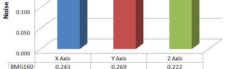

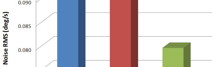
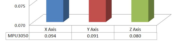
29 Test Procedure Results Noise Tests RMS Noise calculated for each type of sensor 2016, ACUTRONIC 29


30 Test Procedure Results Noise Tests Allan Variance calculated for each type of sensor More data on: Noise and Allan Variance Zero Input Bias Sensitivity Non-Linearity Error Cross-Axis Sensitivity Performance over temperature available from ACUTRONIC 2016, ACUTRONIC 30


31 Test Procedure Results Dynamic Tests Full Scale Range for each type of sensor 2016, ACUTRONIC 31
32 Test Procedure Results Dynamic Tests Cross-Axis Sensitivity for each type of sensor BMG160 MPU3050 L3G3200D Parameter Units Mean Mean Mean Noise gyrox deg/s RMS Noise gyroy deg/s RMS Noise gyroz deg/s RMS AllVar gyrox deg/s/ Hz AllVar gyroy deg/s/ Hz AllVar gyroz deg/s/ Hz Zero Rate Bias gyrox deg/s ±2.63 ±1.744 ±2.139 Zero Rate Bias gyroymore data on: deg/s ±2.593 ±0.880 ±0.671 Zero Rate Bias gyro Z deg/s ±3.010 ±1.582 ±1.203 Noise and Allan Variance Zero Input Bias Sensitivity Non-Linearity Error Cross-Axis Sensitivity Performance over temperature available from ACUTRONIC ZeroRateBiasTempCoef gyrox deg/s/degc /d ± ± ± ZeroRateBiasTempCoef gyroy deg/s/degc ±0.005 ±0.023 ±0.014 ZeroRateBiasTempCoef gyroz deg/s/degc ±0.001 ±0.106 ±0.023 Sensitivity gyrox deg/s/lsb Sensitivity gyroy deg/s/lsb Sensitivity gyroz deg/s/lsb SensitivityTempCoef gyrox %/degc ±0.010 ±0.016 ±0.023 SensitivityTempCoef gyroy %/degc ±0.003 ±0.010 ±0.027 SensitivityTempCoef gyroz %/degc ±0.001 ±0.003 ±0.008 Integral NLE gyrox % FSR ± Integral NLE gyroy % FSR ± Integral NLE gyroz % FSR ± CrossAxis gryoxy % ±0.075 ±0.522 ±1.235 CrossAxis gyroxz % ±1.781 ± ±0.452 CrossAxis gyroyz % ±0.649 ±3.719 ±0.627 CrossAxis gyroyx % ±0.077 ±0.775 ±1.041 CrossAxis gyrozx % ±1.708 ±0.714 ±0.701 CrossAxis gyrozy % ±0.427 ±2.051 ± , ACUTRONIC 32
33 Conclusion Testing Approaches Integrator of MEMS inertial sensors should select testing parameters based on expected application of the device containing MEMS inertial sensors IEEE 2700 Standard should be used to define parameters that are to be tested Test methodology needs to be defined, Acutronic can help Based on test results, developers and integrators can make sensor selection based on specific needs for that t application (i.e. low noise, low bias, high h sensitivity, etc.) This type of testing provides additional differentiation for the MEMS sensors selection process (in addition to cost, size and power requirements) 2016, ACUTRONIC 33
34 Conclusion Testing Approaches For example, in the data set one type of sensor (InvenSense MPU3050) has significantly lower Noise RMS values than the other two sensors If RMS Noise is a very important parameter for the given application this sensor would have been the choice for that application Testing also allows comparison of actual live sensors data to manufacturer s published specifications It provides valuable measurement of quality of performance With that t in mind ACUTRONIC has set up a lab (its Lab) to provide testing ti services to encourage wider application of the IEEE 2700 Standard its Lab enables such testing for all types of inertial MEMS sensors 2016, ACUTRONIC 34
35 Thank you for your attention! For more information contact: Dino Smajlovic , ACUTRONIC 35
EE 570: Location and Navigation: Theory & Practice
 EE 570: Location and Navigation: Theory & Practice Navigation Sensors and INS Mechanization Thursday 14 Feb 2013 NMT EE 570: Location and Navigation: Theory & Practice Slide 1 of 14 Inertial Sensor Modeling
Mio- x AHRS. Attitude and Heading Reference System. Engineering Specifications
 General Description Mio- x AHRS Attitude and Heading Reference System Engineering Specifications Rev. G 2012-05-29 Mio-x AHRS is a tiny sensormodule consists of 9 degree of freedom motion sensors (3 accelerometers,
INTEGRATED TECH FOR INDUSTRIAL POSITIONING
 INTEGRATED TECH FOR INDUSTRIAL POSITIONING Integrated Tech for Industrial Positioning aerospace.honeywell.com 1 Introduction We are the world leader in precision IMU technology and have built the majority
Allan Variance Analysis of Random Noise Modes in Gyroscopes
 Allan Variance Analysis of Random Noise Modes in Gyroscopes Alexander A. Trusov, Ph.D. Alex.Trusov@gmail.com, AlexanderTrusov.com, MEMS.eng.uci.edu MicroSystems Laboratory, Mechanical and Aerospace Engineering
Inertial Navigation Static Calibration
 INTL JOURNAL OF ELECTRONICS AND TELECOMMUNICATIONS, 2018, VOL. 64, NO. 2, PP. 243 248 Manuscript received December 2, 2017; revised April, 2018. DOI: 10.24425/119518 Inertial Navigation Static Calibration
Calibration of Inertial Measurement Units Using Pendulum Motion
 Technical Paper Int l J. of Aeronautical & Space Sci. 11(3), 234 239 (2010) DOI:10.5139/IJASS.2010.11.3.234 Calibration of Inertial Measurement Units Using Pendulum Motion Keeyoung Choi* and Se-ah Jang**
CHARACTERIZATION AND CALIBRATION OF MEMS INERTIAL MEASUREMENT UNITS
 CHARACTERIZATION AND CALIBRATION OF MEMS INERTIAL MEASUREMENT UNITS ökçen Aslan 1,2, Afşar Saranlı 2 1 Defence Research and Development Institute (SAE), TÜBİTAK 2 Dept. of Electrical and Electronics Eng.,
DriftLess Technology to improve inertial sensors
 Slide 1 of 19 DriftLess Technology to improve inertial sensors Marcel Ruizenaar, TNO marcel.ruizenaar@tno.nl Slide 2 of 19 Topics Problem, Drift in INS due to bias DriftLess technology What is it How it
Cross-Domain Development Kit XDK110 Platform for Application Development
 Sensor Guide Cross-Domain Development Kit Platform for Application Development Bosch Connected Devices and Solutions : Data Sheet Document revision 2.1 Document release date 05.10.17 Workbench version
Line of Sight Stabilization Primer Table of Contents
 Line of Sight Stabilization Primer Table of Contents Preface 1 Chapter 1.0 Introduction 3 Chapter 2.0 LOS Control Architecture and Design 11 2.1 Direct LOS Stabilization 15 2.2 Indirect LOS Stabilization
navigation Isaac Skog
 Foot-mounted zerovelocity aided inertial navigation Isaac Skog skog@kth.se Course Outline 1. Foot-mounted inertial navigation a. Basic idea b. Pros and cons 2. Inertial navigation a. The inertial sensors
XDK HARDWARE OVERVIEW
 XDK HARDWARE OVERVIEW Agenda 1 General Overview 2 3 4 Sensors Communications Extension Board 2 General Overview 1. General Overview What is the XDK? The Cross-Domain Development Kit, or XDK, is a battery
Me 3-Axis Accelerometer and Gyro Sensor
 Me 3-Axis Accelerometer and Gyro Sensor SKU: 11012 Weight: 20.00 Gram Description: Me 3-Axis Accelerometer and Gyro Sensor is a motion processing module. It can use to measure the angular rate and the
Frequency Response (min max)
") TDK InvenSense was the first company to deliver Motion Interface solutions with fully integrated sensors and robust MotionFusion firmware algorithms. Their MotionTracking devices enable our customers to
TDK InvenSense was the first company to deliver Motion Interface solutions with fully integrated sensors and robust MotionFusion firmware algorithms. Their MotionTracking devices enable our customers to
Quaternion Kalman Filter Design Based on MEMS Sensors
 , pp.93-97 http://dx.doi.org/10.14257/astl.2014.76.20 Quaternion Kalman Filter Design Based on MEMS Sensors Su zhongbin,yanglei, Kong Qingming School of Electrical and Information. Northeast Agricultural
impulse Series of Rate Table Products Industrial Inertial Guidance Test and Calibration Systems
 impulse Series of Rate Table Products Industrial Inertial Guidance Test and Calibration Systems Building on 45 years of leadership in motion simulation, ACUTRONIC is proud to take inertial testing one
AN5259. LSM6DSOX: Machine Learning Core. Application note. Introduction
 Application note LSM6DSOX: Machine Learning Core Introduction This document is intended to provide information on the Machine Learning Core feature available in the LSM6DSOX. The Machine Learning processing
Monitoring Human Body Motion Denis Hodgins
 Monitoring Human Body Motion Denis Hodgins Lead Partner: ETB Other Partners: Salford IMIT Zarlink Finetech Medical Salisbury Hospital Project Aim To develop a wireless body motion sensing system Applications:
Inertial Measurement Units I!
 ! Inertial Measurement Units I! Gordon Wetzstein! Stanford University! EE 267 Virtual Reality! Lecture 9! stanford.edu/class/ee267/!! Lecture Overview! coordinate systems (world, body/sensor, inertial,
DYNAMIC POSITIONING CONFERENCE September 16-17, Sensors
 DYNAMIC POSITIONING CONFERENCE September 16-17, 2003 Sensors An Integrated acoustic positioning and inertial navigation system Jan Erik Faugstadmo, Hans Petter Jacobsen Kongsberg Simrad, Norway Revisions
Inertial Navigation Systems
 Inertial Navigation Systems Kiril Alexiev University of Pavia March 2017 1 /89 Navigation Estimate the position and orientation. Inertial navigation one of possible instruments. Newton law is used: F =
Navigational Aids 1 st Semester/2007/TF 7:30 PM -9:00 PM
 Glossary of Navigation Terms accelerometer. A device that senses inertial reaction to measure linear or angular acceleration. In its simplest form, it consists of a case-mounted spring and mass arrangement
Sensor Toolbox (Part 2): Inertial Sensors
: Inertial Sensors") November 2010 Sensor Toolbox (Part 2): Inertial Sensors AMF-ENT-T1118 Michael Steffen MCU & Sensor Field Application Engineer Expert Reg. U.S. Pat. & Tm. Off. BeeKit, BeeStack, CoreNet, the Energy Efficient
November 2010 Sensor Toolbox (Part 2): Inertial Sensors AMF-ENT-T1118 Michael Steffen MCU & Sensor Field Application Engineer Expert Reg. U.S. Pat. & Tm. Off. BeeKit, BeeStack, CoreNet, the Energy Efficient
Inertial Measurement Unit (IMU) ISIS-IMU (Rev. C)
 ISIS-IMU (Rev. C)") Inertial Measurement Unit (IMU) ISIS-IMU (Rev. C) Features Fully compensated Inertial Measurement Unit (IMU) DC in digital output Most cost effective IMU - Lowest cost 6 degree of freedom IMU in its performance
Inertial Measurement Unit (IMU) ISIS-IMU (Rev. C) Features Fully compensated Inertial Measurement Unit (IMU) DC in digital output Most cost effective IMU - Lowest cost 6 degree of freedom IMU in its performance
VSEW_mk2-8g. Data Sheet. Dec Bruno Paillard
 VSEW_mk2-8g Data Sheet Dec 4 2017 Bruno Paillard 1 PRODUCT DESCRIPTION 2 2 APPLICATIONS 2 3 SPECIFICATIONS 3 3.1 Frequency Response 5 3.1.1 Upper Frequency Limit 5 3.1.2 Low-Frequency Limit 6 3.2 Noise
APN-065: Determining Rotations for Inertial Explorer and SPAN
 APN-065 Rev A APN-065: Determining Rotations for Inertial Explorer and SPAN Page 1 May 5, 2014 Both Inertial Explorer (IE) and SPAN use intrinsic -order Euler angles to define the rotation between the
Application of FOG for seismic measurements. Alex Velikoseltsev
 Application of FOG for seismic measurements Alex Velikoseltsev INFN Pisa 2012 Seismic rotation measurements: goals Constraining earthquake source processes when observed close to active faults; Estimation
Sensing our world PRODUCT OVERVIEW
 Bosch Sensortec MEMS sensors and solutions Sensing our world PRODUCT OVERVIEW Bosch Sensortec Worldwide presence Kusterdingen Germany Dresden Germany Munich Germany Beijing China Seoul Korea Tokyo Japan
MPU 9250 C Library. Shivansh Singla
 MPU 9250 C Library Shivansh Singla PREFACE These application notes are used for communicating with MPU 9250 via I2C protocol based on the application notes [1] released by Daniel Fiske, Michael Lam and
Camera Drones Lecture 2 Control and Sensors
 Camera Drones Lecture 2 Control and Sensors Ass.Prof. Friedrich Fraundorfer WS 2017 1 Outline Quadrotor control principles Sensors 2 Quadrotor control - Hovering Hovering means quadrotor needs to hold
Sensing our world PRODUCT OVERVIEW
 Bosch Sensortec MEMS sensors and solutions Sensing our world PRODUCT OVERVIEW Bosch Sensortec Worldwide presence Kusterdingen Germany Dresden Germany Munich Germany Beijing China Seoul Korea Tokyo Japan
Autonomous Navigation for Flying Robots
 Computer Vision Group Prof. Daniel Cremers Autonomous Navigation for Flying Robots Lecture 3.2: Sensors Jürgen Sturm Technische Universität München Sensors IMUs (inertial measurement units) Accelerometers
This was written by a designer of inertial guidance machines, & is correct. **********************************************************************
 EXPLANATORY NOTES ON THE SIMPLE INERTIAL NAVIGATION MACHINE How does the missile know where it is at all times? It knows this because it knows where it isn't. By subtracting where it is from where it isn't
MEMSENSE. AccelRate3D. Triaxial Accelerometer & Gyroscope Analog Inertial Sensor
 FUNCTIONAL DESCRIPTION FEATURES The is the world s smallest commercially available analog inertial measurement unit, providing analog outputs of triaxial acceleration and rate of turn (gyro) data. The
Satellite and Inertial Navigation and Positioning System
 Satellite and Inertial Navigation and Positioning System Project Proposal By: Luke Pfister Dan Monroe Project Advisors: Dr. In Soo Ahn Dr. Yufeng Lu EE 451 Senior Capstone Project December 10, 2009 PROJECT
SX Series Inertial Measurement Unit (IMU) Technical User Guide
 Technical User Guide") SX Series Inertial Measurement Unit (IMU) Technical User Guide LMRK01 LMRK005 LMRK007 LMRK007X LMRK60 MRM60 LMRK65 G300D Technical Support Gladiator Technologies Attn: Technical Support 8020 Bracken Place
SX Series Inertial Measurement Unit (IMU) Technical User Guide LMRK01 LMRK005 LMRK007 LMRK007X LMRK60 MRM60 LMRK65 G300D Technical Support Gladiator Technologies Attn: Technical Support 8020 Bracken Place
Using the MPU Inertia Measurement Systems Gyroscopes & Accelerometers Sensor fusion I2C MPU-6050
 Using the MPU-6050 Inertia Measurement Systems Gyroscopes & Accelerometers Sensor fusion I2C MPU-6050 IMUs There are small devices indicating changing orientation in smart phones, video game remotes, quad-copters,
DESIGN CRITERIA AND APPLICATIONS OF MOTION SIMULATORS USED IN RESEARCH AND TESTING OF INERTIAL SENSOR PACKAGES FOR SPACE APPLICATIONS ABSTRACT
 DESIGN CRITERIA AND APPLICATIONS OF MOTION SIMULATORS USED IN RESEARCH AND TESTING OF INERTIAL SENSOR PACKAGES FOR SPACE APPLICATIONS Mr. Florent Leforestier Acutronic Asia Co., Ltd., Beijing, P.R.China,
Fully Integrated Thermal Accelerometer MXC6225XU
 Powerful Sensing Solutions for a Better Life Fully Integrated Thermal Accelerometer MXC6225XU Document Version 1.0 page 1 Features General Description Fully Integrated Thermal Accelerometer X/Y Axis, 8
Bluetooth Embedded Inertial Measurement Unit for Real-Time Data Collection for Gait Analysis
 Bluetooth Embedded Inertial Measurement Unit for Real-Time Data Collection for Gait Analysis Ravi Chandrasiri Sri Lanka Institute of Information Technology Colombo, Sri Lanka ravi.chandrasiri@gmail.com
HOBO Pendant G Data Logger (UA ) White Paper
 White Paper") HOBO Pendant G Data Logger (UA-4-64) White Paper This white paper explains the operation of the HOBO Pendant G data logger (UA-4-64). Operating Principles The accelerometer used in the Pendant G logger
HOBO Pendant G Data Logger (UA-4-64) White Paper This white paper explains the operation of the HOBO Pendant G data logger (UA-4-64). Operating Principles The accelerometer used in the Pendant G logger
Parallax LSM9DS1 9-axis IMU Module (#28065)
") Web Site: www.parallax.com Forums: forums.parallax.com Sales: sales@parallax.com Technical:support@parallax.com Office: (916) 624-8333 Fax: (916) 624-8003 Sales: (888) 512-1024 Tech Support: (888) 997-8267
Web Site: www.parallax.com Forums: forums.parallax.com Sales: sales@parallax.com Technical:support@parallax.com Office: (916) 624-8333 Fax: (916) 624-8003 Sales: (888) 512-1024 Tech Support: (888) 997-8267
Selection and Integration of Sensors Alex Spitzer 11/23/14
 Selection and Integration of Sensors Alex Spitzer aes368@cornell.edu 11/23/14 Sensors Perception of the outside world Cameras, DVL, Sonar, Pressure Accelerometers, Gyroscopes, Magnetometers Position vs
Programming-By-Example Gesture Recognition Kevin Gabayan, Steven Lansel December 15, 2006
 Programming-By-Example Gesture Recognition Kevin Gabayan, Steven Lansel December 15, 6 Abstract Machine learning and hardware improvements to a programming-by-example rapid prototyping system are proposed.
Attitude and Heading Reference System AHRS. Interface Control Document
 Attitude and Heading Reference System AHRS Revision 1.8 1 CHANGE STATUS LOG DOCUMENT: Inertial Labs TM AHRS REVISION DATE AFFECTED PARAGRAPHS REMARKS 1.0 Jan. 19, 2012 All Released version. 1.1 Feb. 06,
IMU06WP. What is the IMU06?
 IMU06 What is the IMU06? The IMU06 is a compact 6 degree of freedom inertial measurement unit. It provides 3 axis acceleration (maximum 10G) and angular velocities (maximum 300 degrees/s) on both CAN and
Movit System G1 WIRELESS MOTION DEVICE SYSTEM
 Movit System G1 WIRELESS MOTION DEVICE SYSTEM 1 INTRODUCTION The Movit System G1 incorporates multiple wireless motion devices (Movit G1) with the Dongle G1 station, dedicated software and a set of full
Sensing our world PRODUCT OVERVIEW
 Bosch Sensortec MEMS sensors and solutions Sensing our world PRODUCT OVERVIEW Bosch Sensortec Worldwide presence Kusterdingen Germany Dresden Germany Munich Germany Beijing China Seoul Korea Tokyo Japan
Datasheet 2102 SERIES TWO-AXIS POSITIONING AND RATE TABLE SYSTEM
 Datasheet 2102 SERIES TWO-AXIS POSITIONING AND RATE TABLE SYSTEM FEATURES Position Accuracy: ± 30 arc seconds (both axes) Rate Accuracy: ± 0.01% Max Rate (varies depending on axis configuration): Inner
Orientation Capture of a Walker s Leg Using Inexpensive Inertial Sensors with Optimized Complementary Filter Design
 Orientation Capture of a Walker s Leg Using Inexpensive Inertial Sensors with Optimized Complementary Filter Design Sebastian Andersson School of Software Engineering Tongji University Shanghai, China
Attitude and Heading Reference System AHRS-II
 Attitude and Heading Reference System AHRS-II Revision 1.7 Tel: +1 (703) 880-4222, Fax: +1 (703) 935-8377 Website: www.inertiallabs.com 1 CHANGE STATUS LOG DOCUMENT: Inertial Labs TM AHRS REVISION DATE
Satellite Attitude Determination
 Satellite Attitude Determination AERO4701 Space Engineering 3 Week 5 Last Week Looked at GPS signals and pseudorange error terms Looked at GPS positioning from pseudorange data Looked at GPS error sources,
 FUNCTIONAL DESCRIPTION The is a complete triaxial angular rate sensor based on a surface-micromachining technology capable of sensing angular motion about three orthogonal axes. The provides analog outputs
ECV ecompass Series. Technical Brief. Rev A. Page 1 of 8. Making Sense out of Motion
 Technical Brief The ECV ecompass Series provides stable azimuth, pitch, and roll measurements in dynamic conditions. An enhanced version of our ECG Series, the ECV includes a full suite of precision, 3-axis,
9 Degrees of Freedom Inertial Measurement Unit with AHRS [RKI-1430]
![9 Degrees of Freedom Inertial Measurement Unit with AHRS [RKI-1430]](/thumbs/86/94257860.jpg "9 Degrees of Freedom Inertial Measurement Unit with AHRS [RKI-1430]") 9 Degrees of Freedom Inertial Measurement Unit with AHRS [RKI-1430] Users Manual Robokits India info@robokits.co.in http://www.robokitsworld.com Page 1 This 9 Degrees of Freedom (DOF) Inertial Measurement
9 Degrees of Freedom Inertial Measurement Unit with AHRS [RKI-1430] Users Manual Robokits India info@robokits.co.in http://www.robokitsworld.com Page 1 This 9 Degrees of Freedom (DOF) Inertial Measurement
DATASHEET SQ-SI-360DA-VMP SOLID-STATE MEMS INCLINOMETER ±70 º DUAL AXIS, 360 º SINGLE AXIS, SERIAL AND ANALOG OUTPUT FUNCTIONAL DIAGRAMS
 Output Voltage (volts) DATASHEET FUNCTIONAL DIAGRAMS -HMP -VMP FUNCTION ± 70 º dual axis angle measurement 360 º single axis angle measurement UART serial output and analog output APPLICATIONS Platform
STAC5 Stepper Drives. A high performance, compact and cost-effective stepper drive with advanced features and control options
 STAC5 Stepper Drives A high performance, compact and cost-effective stepper drive with advanced features and control options Ethernet & EtherNet/IP Advanced Current Control Anti-Resonance Torque Ripple
Development of a Ground Based Cooperating Spacecraft Testbed for Research and Education
 DIPARTIMENTO DI INGEGNERIA INDUSTRIALE Development of a Ground Based Cooperating Spacecraft Testbed for Research and Education Mattia Mazzucato, Sergio Tronco, Andrea Valmorbida, Fabio Scibona and Enrico
AN 038. Getting Started with the KXTJ2. Introduction
 Getting Started with the KXTJ2 Introduction This application note will help developers quickly implement proof-of-concept designs using the KXTJ2 tri-axis accelerometer. Please refer to the KXTJ2 data
DATASHEET SQ-SI-360DA-VMP SOLID-STATE MEMS INCLINOMETER ±70 º DUAL AXIS, 360 º SINGLE AXIS, SERIAL AND ANALOG OUTPUT. -Az RANGE AND SCALE
 Gravity -Az -Ax +A θ φ -HMP -VMP DESCRIPTION The inclinometer module performs calibrated angle measurement with analog voltage and digital serial outputs. FUNCTION ± 70 º dual axis angle measurement 360
Inertial Measurement for planetary exploration: Accelerometers and Gyros
 Inertial Measurement for planetary exploration: Accelerometers and Gyros Bryan Wagenknecht 1 Significance of Inertial Measurement Important to know where am I? if you re an exploration robot Probably don
BNO055 Quick start guide
 BNO055 Quick start guide Bosch Sensortec Application note: BNO055 Quick start guide Document revision 1.0 Document release date Document number Mar.2015 BST-BNO055-AN007-00 Technical reference code 0 273
Inertial Systems. Ekinox Series TACTICAL GRADE MEMS. Motion Sensing & Navigation IMU AHRS MRU INS VG
 Ekinox Series TACTICAL GRADE MEMS Inertial Systems IMU AHRS MRU INS VG ITAR Free 0.05 RMS Motion Sensing & Navigation AEROSPACE GROUND MARINE Ekinox Series R&D specialists usually compromise between high
Geometry Measurements
 Geometry Measurements Welcome to our world Since the very beginning in 1984, ACOEM AB has helped industries throughout the world to achieve more profitable and sustainable production. We have reached where
Sphero Lightning Lab Cheat Sheet
 Actions Tool Description Variables Ranges Roll Combines heading, speed and time variables to make the robot roll. Duration Speed Heading (0 to 999999 seconds) (degrees 0-359) Set Speed Sets the speed of
Performance Evaluation of INS Based MEMES Inertial Measurement Unit
 Int'l Journal of Computing, Communications & Instrumentation Engg. (IJCCIE) Vol. 2, Issue 1 (215) ISSN 2349-1469 EISSN 2349-1477 Performance Evaluation of Based MEMES Inertial Measurement Unit Othman Maklouf
DATASHEET SOLID-STATE WIDE RANGE MEMS INCLINOMETER 360 º X 180 º DUAL AXIS, SERIAL AND ANALOG OUTPUT FUNCTIONAL DIAGRAM EXAMPLE ANALOG OUTPUT
 Output Voltage (volts) DATASHEET FUNCTIONAL DIAGRAM -HMP FUNCTION Wide range 360 º x 180 º dual axis angle measurement UART serial output and analog output APPLICATIONS Platform and vehicle leveling Satellite
Technical Document Compensating. for Tilt, Hard Iron and Soft Iron Effects
 Technical Document Compensating for Tilt, Hard Iron and Soft Iron Effects Published: August 6, 2008 Updated: December 4, 2008 Author: Christopher Konvalin Revision: 1.2 www.memsense.com 888.668.8743 Rev:
Simplified Orientation Determination in Ski Jumping using Inertial Sensor Data
 Simplified Orientation Determination in Ski Jumping using Inertial Sensor Data B.H. Groh 1, N. Weeger 1, F. Warschun 2, B.M. Eskofier 1 1 Digital Sports Group, Pattern Recognition Lab University of Erlangen-Nürnberg
High Performance IMUs and Accelerometers
 High Performance IMUs and Accelerometers Small IMU IMU -0- CAN interface Accelerometer NOTICE No part of this material may be reproduced or duplicated in any form or by any means without the written permission
Power Density. Digital Control. Improvements and. Techniques Enabling. Power Management Capabilities. Technical Paper 004
 Digital Control Techniques Enabling Power Density Improvements and Power Management Capabilities Technical Paper 004 First presented at PCIM China 2007 Digital control can be used as an enabling technology
2011 FIRST Robotics Competition Sensor Manual
 2011 FIRST Robotics Competition Sensor Manual The 2011 FIRST Robotics Competition (FRC) sensors are outlined in this document. It is being provided as a courtesy, and therefore does not supersede any information
USB Virtual Reality HID. by Weston Taylor and Chris Budzynski Advisor: Dr. Malinowski
 USB Virtual Reality HID by Weston Taylor and Chris Budzynski Advisor: Dr. Malinowski Project Summary Analysis Block Diagram Hardware Inertial Sensors Position Calculation USB Results Questions === Agenda
Analyses of Electronic Inclinometer Data for Tri-axial Accelerometer s Initial Alignment
 Martin ŠIPOŠ, Jan ROHÁČ, Petr NOVÁČEK Czech Technical University in Prague () Analyses of Electronic Inclinometer Data for Tri-axial Accelerometer s Initial Alignment Abstract. This paper deals with the
Micro Inertial Navigation System. - Present Status and Development at Imego AB.
 Micro Inertial Navigation System - Present Status and Development at Imego AB www.imego.com Page 1 (2) Executive Summary Imego has developed a very small prototype system for inertial navigation based
Driver Installation IMU Data Console IMU Demo. Documentation Revision
 Driver Installation IMU Data Console IMU Demo Documentation Revision 1 www.memsense.com 888.668.8743 1 DRIVER INSTALLATION... 2 1.1 IDENTIFYING PROTOCOL... 2 1.2 INSTALLATION... 2 1.3 HARDWARE SETUP...4
Sensing our world PRODUCT OVERVIEW
 Bosch Sensortec MEMS sensors and solutions Sensing our world PRODUCT OVERVIEW Bosch Sensortec Worldwide presence Kusterdingen Germany Dresden Germany Munich Germany Beijing China Seoul Korea Tokyo Japan
Test Report iµvru. (excerpt) Commercial-in-Confidence. imar Navigation GmbH Im Reihersbruch 3 D St. Ingbert Germany.
 Commercial-in-Confidence. imar Navigation GmbH Im Reihersbruch 3 D St. Ingbert Germany.") 1 of 11 (excerpt) Commercial-in-Confidence imar Navigation GmbH Im Reihersbruch 3 D-66386 St. Ingbert Germany www.imar-navigation.de sales@imar-navigation.de 2 of 11 CHANGE RECORD Date Issue Paragraph
1 of 11 (excerpt) Commercial-in-Confidence imar Navigation GmbH Im Reihersbruch 3 D-66386 St. Ingbert Germany www.imar-navigation.de sales@imar-navigation.de 2 of 11 CHANGE RECORD Date Issue Paragraph
Windows Phone Week5 Tuesday -
 Windows Phone 8.1 - Week5 Tuesday - Smart Embedded System Lab Kookmin University 1 Objectives and what to study Training 1: To Get Accelerometer Sensor Value Training 2: To Get Compass Sensor Value To
CENG4480 Embedded System Development and Applications The Chinese University of Hong Kong Laboratory 6: IMU (Inertial Measurement Unit)
") CENG4480 Embedded System Development and Applications The Chinese University of Hong Kong Laboratory 6: IMU (Inertial Measurement Unit) Student ID: 2018 Fall 1 Introduction In this exercise you will learn
CENG4480 Embedded System Development and Applications The Chinese University of Hong Kong Laboratory 6: IMU (Inertial Measurement Unit) Student ID: 2018 Fall 1 Introduction In this exercise you will learn
An Intro to Gyros. FTC Team #6832. Science and Engineering Magnet - Dallas ISD
 An Intro to Gyros FTC Team #6832 Science and Engineering Magnet - Dallas ISD Gyro Types - Mechanical Hubble Gyro Unit Gyro Types - Sensors Low cost MEMS Gyros High End Gyros Ring laser, fiber optic, hemispherical
Limits of Absolute Heading Accuracy Using Inexpensive MEMS Sensors
 Limits of Absolute Heading Accuracy Using Inexpensive MEMS Sensors Gregory Tomasch and Kris Winer Tlera Corporation tleracorp@gmail.com March 11, 2019 Abstract We measure the absolute heading accuracy
MEMS & Sensors for wearable electronics. Jérémie Bouchaud Director and Senior Principal Analyst IHS Technology
 MEMS & Sensors for wearable electronics Jérémie Bouchaud Director and Senior Principal Analyst IHS Technology Outline Wearable electronics market overview MEMS & Sensors in wearable Motion sensors MEMS
Related products: SAA Field Power Unit
 SAAScan Model 003 Measurand s ShapeArray is a flexible, calibrated shape measuring system. It measures 2D and 3D shape and 3D vibration using a compact array of MEMs accelerometers. SAAScan is a special
Related products: SAA Field Power Unit
 SAAScan Model 003 Measurand s ShapeArray is a flexible, calibrated shape measuring system. It measures 2D and 3D shape and 3D vibration using a compact array of MEMs accelerometers. SAAScan is a special
DE2.3 Electronics 2. Lab Experiment 3: IMU and OLED Display
 Objectives Dyson School of Design Engineering DE2.3 Electronics 2 Lab Experiment 3: IMU and OLED Display (webpage: http://www.ee.ic.ac.uk/pcheung/teaching/de2_ee/) By the end of this experiment, you should
Unit 2: Locomotion Kinematics of Wheeled Robots: Part 3
 Unit 2: Locomotion Kinematics of Wheeled Robots: Part 3 Computer Science 4766/6778 Department of Computer Science Memorial University of Newfoundland January 28, 2014 COMP 4766/6778 (MUN) Kinematics of
EE565:Mobile Robotics Lecture 2
 EE565:Mobile Robotics Lecture 2 Welcome Dr. Ing. Ahmad Kamal Nasir Organization Lab Course Lab grading policy (40%) Attendance = 10 % In-Lab tasks = 30 % Lab assignment + viva = 60 % Make a group Either
Strapdown Inertial Navigation Technology
 Strapdown Inertial Navigation Technology 2nd Edition David Titterton and John Weston The Institution of Engineering and Technology Preface xv 1 Introduction 1 1.1 Navigation 1 1.2 Inertial navigation 2
Sensor fusion for motion processing and visualization
 Sensor fusion for motion processing and visualization Ali Baharev, PhD TÁMOP 4.2.2 Szenzorhálózat alapú adatgyűjtés és információfeldolgozás workshop April 1, 2011 Budapest, Hungary What we have - Shimmer
K-Beam Accelerometer. Acceleration. Capacitive MEMS, Triaxial Accelerometer. Type 8395A...
 Acceleration K-Beam Accelerometer Type 8395A... Capacitive MEMS, Triaxial Accelerometer Type 8395A is a high-sensitivity, low noise triaxial accelerometer which simultaneously measures acceleration and/or
STEPPER MOTOR DRIVES SOME FACTORS THAT WILL HELP DETERMINE PROPER SELECTION
 SOME FACTORS THAT WILL HELP DETERMINE PROPER SELECTION Authored By: Robert Pulford and Engineering Team Members Haydon Kerk Motion Solutions This white paper will discuss some methods of selecting the
Low Power Gesture Recognition
 Low Power Gesture Recognition Semester Project Student: Severin Mutter Supervisors: Pascal Bissig Prof. Dr. Roger Wattenhofer March 2014 June 2014 Abstract This thesis describes the concept and the design
New paradigm for MEMS+IC Co-development
 New paradigm for MEMS+IC Co-development MEMS 진보된스마트세상을만듭니다. Worldwide First MEMS+IC Co-development Solution New paradigm for MEMS+IC Co-development A New Paradigm for MEMS+IC Development MEMS design
Testing the Possibilities of Using IMUs with Different Types of Movements
 137 Testing the Possibilities of Using IMUs with Different Types of Movements Kajánek, P. and Kopáčik A. Slovak University of Technology, Faculty of Civil Engineering, Radlinského 11, 81368 Bratislava,
Specification G-NSDOG2-200
 ±90deg Inclinometer with CAN J1939 interface Version 1.2 Contents 1 History 3 2 Applicable Documents 3 3 Description of the G-NSDOG2 inclinometer 4 4 Mechanics and Connections 4 4.1 Mechanical data 4 4.2
J1939 VIM : Vehicle Inertia Monitor
 J1939 VIM : Vehicle Inertia Monitor Advanced J1939 Vehicle Inertial Measurement and Vibration Monitoring Device Features: DSP Microcontroller Hosts Advanced Data Processing Algorithms and Applications
LOW COST CVG FOR HIGH-GRADE NORTH FINDERS AND TARGETING SYSTEMS
 LOW COST CVG FOR HIGH-GRADE NORTH FINDERS AND TARGETING SYSTEMS J. Beitia 1, C. Fell 2, I. Okon 3, P. Sweeney 4, D. Simonenko 5 INNALABS Ltd, Snugborough Rd, Blanchardstown, Dublin 15, IRELAND Email: jose.beitia@innalabs.com,
K-Beam Accelerometer. Acceleration. Capacitive MEMS, Triaxial Accelerometer. Type 8396A...
 Acceleration K-Beam Accelerometer Type 8396A... Capacitive MEMS, Triaxial Accelerometer Type 8396A is a high-sensitivity, low noise triaxial accelerometer which simultaneously measures acceleration and/or
Vibration analysis goes mainstream
 Vibration analysis goes mainstream With advances in sensor, recording, and analysis technology, vibration analysis is now within the reach of even small organizations Fast Forward Measuring the vibrations