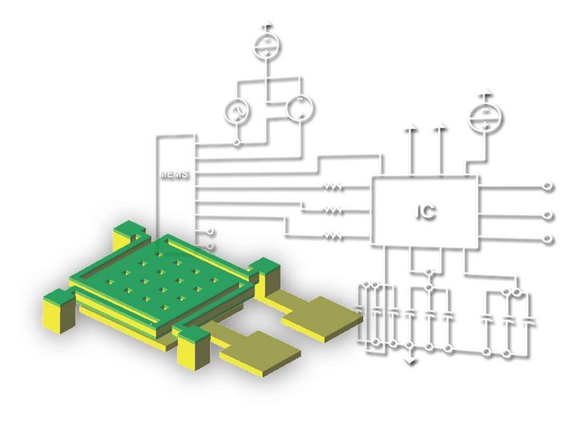
New paradigm for MEMS+IC Co-development
|
|
|
- Kristina Jefferson
- 5 years ago
- Views:
Transcription

1 New paradigm for MEMS+IC Co-development


2 MEMS 진보된스마트세상을만듭니다.

3 Worldwide First MEMS+IC Co-development Solution


4

5

6 New paradigm for MEMS+IC Co-development
7 A New Paradigm for MEMS+IC Development MEMS design System Design (MEMS+IC) Design Definition MEMS+ parametric model CoventorWare field solvers MATLAB Simulink Refinement, Optimization, Issue Resolution MEMS+ parametric model CoventorWare field solvers MATLAB Simulink Cadence Verification MEMS+ parametric model CoventorWare field solvers Cadence Coventor Inc Slide 7
8 Introducing MEMS+ Agenda What is MEMS+ Why use MEMS+ How does MEMS+ work What s New in MEMS+ 4.0 Conclusion Slide 8


9 What is MEMS+? A tool for creating compact finite element models that run in MATLAB, Simulink, and Cadence Enter Design in 3D Simulate and Analyze MEMS+ Simulator Visualize Results in 3D MATLAB Simulink Virtuoso MEMS+ Finite Element Library: MEMS-specific, 3D, high-order, parametric Slide 9


10 Why Use MEMS+? or what MEMS+ can do for you


11 Why use MEMS+ MEMS present specific simulation challenges MEMS are multi-physics Mechanics + electrostatics + fluidic effects + packaging effects + etc. MEMS are part of a system MEMS + control system MEMS + IC MEMS+ can simulate fully coupled physics Dynamic response Rapid design studies Design optimization MEMS+ models work in system and IC tools Closed-loop operation Noise analysis Device arrays Slide 11

12 Why use MEMS+? MEMS are multi-physics Need to quickly evaluate design concepts? MEMS+ has an easy-to-use UI for building parametric models, with built-in simulator, and MATLAB and Python scripting interfaces Beam Width = 5u Beam Width = 6u Beam Width = 7u Result of a vary analysis exploring different design geometries Slide 12

13 Why use MEMS+? MEMS are multi-physics Need to study the dynamic response of your sensor? MEMS+ model of a gyroscope, MEMS+ model includes mechanical, electrical and gas damping effects, and is small enough for fast transient simulations in Simulink or Cadence Transient response to angular acceleration, simulated in minutes on a laptop Coventor Inc Slide 13

14 Why use MEMS+? MEMS are multi-physics Need to study the dynamic response of your actuator? MEMS+ models are very fast and can easily combine mechanical, electrical and fluidic effects in a transient simulation Simulated gas pressure on electrodes as RF switch closes Tip position (m) RF switch tip position, closing and opening Time (s) Slide 14

15 Why use MEMS+? MEMS are multi-physics Need to assess packaging effects on your sensor? MEMS+ can predict how thermal effects on your package will affect critical sensor outputs such as zero-offset in accelerometers Simulated zero-offset vs. temperature for z-axis of 3-axis accelerometer

16 Why use MEMS+? MEMS are part of a system Need to simulate closed-loop control of your sensor? 3D accelerometer design in MEMS+ Simulink diagram: accelerometer with sigma-delta controller MEMS+ models plug into Simulink Non-linear Parametric Fast and accurate Slide 16


17 Force-feedback control of accelerometer Input acceleration: a y = sin( t) at 256 Hz Error capacitance Concept: Use controller to hold proof mass steady for any acceleration, and use feedback control signal as output. Output bitstream & control signal Coventor Inc Low-pass filtered output signal


18 System stability simulations in Simulink with MEMS+ model 256 Hz input acceleration Single-DoF results y DoF only Multi-DoF results Unrestricted motion Unstable: Noise grows until the combs pull-in! Coventor Inc Slide 18


19 System stability simulations MEMS are part of a system Need help to understand your measured results? Instead, load into MEMS+ to visually observe device behavior: 1-DOF model in MEMS+ Multi-DoF model MEMS+ 1-DOF model erroneously considers the system stable Controller excites suspensions into flapping uncontrollably Slide 19


20 MEMS+ models enable parametric studies Need to study manufacturability? MEMS+ model + MATLAB script 10 minutes CPU time to compute 400 mode frequencies Young s Y-mode Modulus Frequency variation Polysilicon Z-mode Frequency thickness Example: Modal frequencies vs. process variations across wafers

21 Why use MEMS+? MEMS are part of a system Need to provide a MEMS model to your IC designers? Import a MEMS+ model to a Cadence Virtuoso schematic with a few button clicks Cadence Virtuoso schematic Include all essential nonlinearities Selectively linearize for speed MEMS+ model of an SOI gyroscope MEMS Gyroscope Coventor Inc Slide 21
22 Why use MEMS+? MEMS are part of a system Need to simulate an array of actuators? MEMS+ models capture non-linear effects and simulates fast Cadence Virtuoso schematic of a mirror array Cadence Spectre simulation results visualized in MEMS+ Slide 22

 effects MEMS+ symbol in a Cadence Virtuoso")
23 Why use MEMS+? MEMS are part of a system Need to perform noise analysis of your sensor? MEMS+ models support noise analysis in Cadence Spectre and accurately predict thermo-mechanical noise MEMS+ includes all relevant noise sources in your MEMS+IC system, enabling you to improve your signal to noise ratio MEMS+ model of a microphone MEMS+ model includes mechanics, electrostatics and fluidics (air pressure) effects MEMS+ symbol in a Cadence Virtuoso schematic Noise analysis in Cadence Spectre Slide 23

24 How does MEMS+ work? or how to create compact FE model Analog Devices, Inc. All rights reserved


25 MEMS+ a different kind of FEA Traditional Finite Element Analysis 3D Geometry MEMS+ Finite Element Analysis Library of parametric, MEMS-specific, high-order finite elements Library of generic, low-order finite elements Mesh Generator Brick, tet, shell, and beam elements 3D Design Entry in Graphical UI or Scripting in MATLAB or Python Meshed Model Large 10k to 10M DoF Meshed Model Small 10 to 1000 DoF


26 Overview of the MEMS+ Element Library Start with Mechanical Components Rigid Shapes Flexible Shapes Beams Suspensions Add Electro- Mechanical Coupling In-Plane Electrodes Side Electrodes Interdigitated Combs Piezo Layers Add Fluid Damping and Loading Squeezed-Film Damping Fluid Chambers Pressure Loads Slide 26


27 MEMS+ Meshed Models Users assemble MEMS-specific, high-order finite elements to create complex structures: Straight Beam Quadrilateral Shape Rectangular Shape Pie Shape Slide 27
28 MEMS+ Application Examples Accelerometer, 67 DoF Gyroscope, 96 DoF Ring Gyro, 345 DoF DLP mirror, 11 DoF Ring Resonator, 727 DoF RF Switch 119 DoF The MEMS+ approach is general: it has been used to create compact, accurate models of many real-world MEMS designs Slide 28
29 MEMS+ benefits Benefits of the MEMS+ high-order FEM approach: Simulation Speed Parameterization Compatibility Slide 29
30 MEMS+ Benefit: Simulation Speed Auto-meshed models are huge and require long simulation times MEMS+ models are tiny in comparison User Benefits: MEMS+ FE-Model Multi-physics analysis in minutes Transient simulations in minutes or hours Arrays Auto Meshed models are simply too big to run fast! Slide 30


31 MEMS+ Benefit: Parameterization MEMS+ offers a direct way to create efficient parametric models using high-order, MEMS-specific finite elements Parameters may include geometric, process, material and environmental variables Finger Length Enables design optimization, parameter studies, sensitivity, yield and Monte Carlo analysis Slide 31


32 MEMS+ Benefit: Compatibility Auto-meshed models are huge and require proprietary solver to run Auto Meshed FE-Model MEMS+ FE-Model MEMS+ Solver Matlab Simulink Cadence Virtuoso


33 MEMS+ Benefit: Compatibility MEMS+ Model Enables system level, MEMS/IC co-simulation and noise analysis Provides access to many existing tool boxes for design and system optimization Slide 33

34 What s New in MEMS+ 4.0 a new paradigm for MEMS+IC co-design Full MEMS+ model Exported Verilog-A
35 What s New in MEMS+ 4.0 Ability to export models in Verilog-A format Exported models simulate up to 100X faster Compatible with most A/MS simulators, not just Cadence Enables MEMS designers to share models with ASIC developers More capacity and speed Full 64-bit implementation to handle larger, more detailed models New sparse solver for modal analysis Faster loading of large models More modeling options New geometry options for curved combs, useful in gyro designs Selectively include fringing fields for in-plane motion Out-of-plane angle and length scale for imported package Save reaction forces and moments for verification Slide 35

 Preserves selected")

36 MEMS+ 4.0 offers two paths to MEMS+IC co-design MEMS+ model MEMS+IC schematic Imported MEMS symbol Full MEMS+ model New Exported Verilog-A Model Order Reduction (MOR) Preserves selected mechanical modes Reduces from 1000s to <10 DoF Preserves selected non-linear inputs Exported Verilog-A models Simulate up to 100X faster Compatible with most A/MS simulators Protect MEMS design IP Slide 36

 Speed-up vs. full MEMS+ model Coriolis force 0.27 255X Coriolis force and DC bias 1.")
37 Dual-Mass Gryo Example Drive Mode Key Mechanical Modes Transient Simulation in Cadence Spectre response to angular acceleration pulse, 40ms real time Full MEMS+ model Sense Mode Exported Verilog-A Performance on Transient Simulation Verilog-A model with 2 nd -order non-linearities Simulation time per real time (s/ms) Speed-up vs. full MEMS+ model Coriolis force X Coriolis force and DC bias X Slide 37
38 Exported Verilog-A vs. Full MEMS+ Models Model Characteristic Full MEMS+ Exported Verilog-A Included MEMS physics Mechanics, electrostatics, gas damping, piezo effects, package effects Same as full model except noise simulation Nonlinearities All input and state vars Selected input vars Parametric Yes No 3D Result Visualization Yes No Applicable device types Simulation speed Sensors (motion, mics, ), resonators, actuators Selective simplification for speed/accuracy trade-off Same, except devices that depend on pull-in instability Up to 100X faster Compatible simulators Cadence Spectre and APS Most A/MS simulators Protects MEMS device IP No Yes Expected usage: Verilog-A models will be used for routine simulations while full MEMS+ models will be used to investigate anomalous behavior and design corners Slide 38
39 Applicable Device Types for Exported Verilog-A Applicable to sensors and resonators, devices that have small displacement compared to air gap, including Accelerometers Gyros Microphones Pressure sensors Electrostatically-actuated resonators Energy harvesters Scanning mirrors (small motion) Not applicable for electrostatic pull-in analysis of sensors, or actuators that depend on pull-in for intended function, including Switches Varactors (tunable capacitors) Digital display mirrors Shutters Scanning mirrors (large motion) These limitations apply to MEMS Future releases will have more capabilities Slide 39
40 Customer Quote on Exported Verilog-A Tero Sillanpää, ASIC Design Manager, Murata: The Verilog-A Reduced Order Model (ROM) exported from MEMS+ 4.0 captures second order effects not seen in basic hand-crafted models without any compromise in simulation performance. We were able to create a Verilog-A ROM of a complex gyro design in just a few minutes, allowing our ASIC team to work in parallel with the MEMS team on further design iterations. Harmonic simulations in Cadence showed that the model maintained the expected modal frequencies and was stable. Moreover, transient startup simulations were very fast, on the order of 25s CPU time for 1s real time, before front-end electronic components including RC parasitic were added. The robust model exchange between MEMS and ASIC designers enabled by MEMS+ reduces the probability of design error and can help avoid costly redesign iterations needed to address unexpected behavior. Exported Verilog-A models have significant advantages over hand-crafted models Slide 40
41 Licensing of Verilog-A Export Verilog-A Export requires a new license key The license key is required to export Verilog-A from MEMS+ Running exported Verilog-A in Cadence or any other A/MS simulator is unlicensed. Verilog-A Export is a new option on our price list It is an add-on to any MEMS+ bundle For multi-seat quotes, the number of Verilog-A Export licenses should be the same as the number of seats Positive customer response indicates this is a high-value feature. Slide 41
42 In Conclusion: MEMS+ models have significant benefits over traditional FEA Much faster simulations due to reduced degrees of freedom Parameterization enables rapid design exploration and optimization Compatible with MATLAB, Simulink and Cadence simulators MEMS+ goes well beyond traditional FEA capabilities Simulate the dynamic response of sensors and actuators with fully coupled physics Simulate closed-loop operation of sensors Perform noise analysis of sensors MEMS+ 4.0 enables a new level of MEMS+IC co-design Exported Verilog-A models simulate much faster with sufficient accuracy Compatible with most A/MS simulators that take Verilog-A input Share models with partners and customers while protecting MEMS IP Slide 47


43 감사합니다 이디앤씨노용주상무
Speed, Accuracy and Automation in MEMS Simulation and Development C. J. Welham, Coventor, Paris
 Speed, Accuracy and Automation in MEMS Simulation and Development C. J. Welham, Coventor, Paris MEMS Design & Simulation Challenges Overview Simulation Challenges and Approaches Validation Case Studies
CoventorWare 10 Overview
 CoventorWare 10 Overview 노용주 이디앤씨 June, 2015 Distributed and supported by ED&C CoventorWare: Coventor s MEMS Multi-Physics Platform for 10+ Years Sensing Mechanical Electrical Transduction Accelerometers
May 12, 颜军 Jun Yan, Ph.D.
 MEMS Modelling May 12, 2015 颜军 Jun Yan, Ph.D. Technical Director MEMS, Coventor MEMS Modeling 微机电系统模型 MEMS+ CoventorWare SEMulator3D MEMS Design Automation 微机电系统自动化设计 high-order FEA 高阶有限元分析 Cadence Virtuoso
CHAPTER 4 DESIGN AND MODELING OF CANTILEVER BASED ELECTROSTATICALLY ACTUATED MICROGRIPPER WITH IMPROVED PERFORMANCE
 92 CHAPTER 4 DESIGN AND MODELING OF CANTILEVER BASED ELECTROSTATICALLY ACTUATED MICROGRIPPER WITH IMPROVED PERFORMANCE 4.1 INTRODUCTION Bio-manipulation techniques and tools including optical tweezers,
Accelerating Finite Element Analysis in MATLAB with Parallel Computing
 MATLAB Digest Accelerating Finite Element Analysis in MATLAB with Parallel Computing By Vaishali Hosagrahara, Krishna Tamminana, and Gaurav Sharma The Finite Element Method is a powerful numerical technique
CoventorWare Tutorial. Presented by Brian Pepin 11/07/2011
 CoventorWare Tutorial Presented by Brian Pepin 11/07/2011 Downloading Software CoventorWare 2010 Full Release available at http://www.coventor.com/mems/download.html Click on link to download CoventorWare
Simulating Microsystems
 Simulating Microsystems David Bindel UC Berkeley, EECS Simulating Microsystems p.1/21 Overview Microsystems overview Simulation software Case study: gap-closing actuator Simulating Microsystems p.2/21
COMPUTER AIDED ENGINEERING. Part-1
 COMPUTER AIDED ENGINEERING Course no. 7962 Finite Element Modelling and Simulation Finite Element Modelling and Simulation Part-1 Modeling & Simulation System A system exists and operates in time and space.
PTC Newsletter January 14th, 2002
 PTC Email Newsletter January 14th, 2002 PTC Product Focus: Pro/MECHANICA (Structure) Tip of the Week: Creating and using Rigid Connections Upcoming Events and Training Class Schedules PTC Product Focus:
Design Optimization of a Weather Radar Antenna using Finite Element Analysis (FEA) and Computational Fluid Dynamics (CFD)
 and Computational Fluid Dynamics (CFD)") Design Optimization of a Weather Radar Antenna using Finite Element Analysis (FEA) and Computational Fluid Dynamics (CFD) Fernando Prevedello Regis Ataídes Nícolas Spogis Wagner Ortega Guedes Fabiano Armellini
Design Optimization of a Weather Radar Antenna using Finite Element Analysis (FEA) and Computational Fluid Dynamics (CFD) Fernando Prevedello Regis Ataídes Nícolas Spogis Wagner Ortega Guedes Fabiano Armellini
Simulation of a Dual Axis MEMS Seismometer for Building Monitoring System
 Simulation of a Dual Axis MEMS Seismometer for Building Monitoring System Muhammad Ali Shah *, Faisal Iqbal, and Byeung-Leul Lee Korea University of Technology and Education, South Korea * Postal Address:
Optic fiber cores. mirror. fiber radius. centerline FMF. FMF distance. mirror tilt vs. necessary angular precision (fiber radius = 2 microns) 1.
 1.") Comparative Study of 2-DOF Micromirrors for Precision Light Manipulation Johanna I. Young and Andrei M. Shkel Microsystems Laboratory, Department of Mechanical and Aerospace Engineering, University of
Comparative Study of 2-DOF Micromirrors for Precision Light Manipulation Johanna I. Young and Andrei M. Shkel Microsystems Laboratory, Department of Mechanical and Aerospace Engineering, University of
SUGAR: Simulating MEMS
 SUGAR: Simulating MEMS David Bindel UC Berkeley, CS Division SUGAR: Simulating MEMS p.1/30 Outline SUGAR group and research goals Microsystems overview Simulation methodology Software architecture Research
ANSYS Element. elearning. Peter Barrett October CAE Associates Inc. and ANSYS Inc. All rights reserved.
 ANSYS Element Selection elearning Peter Barrett October 2012 2012 CAE Associates Inc. and ANSYS Inc. All rights reserved. ANSYS Element Selection What is the best element type(s) for my analysis? Best
Keywords: Micromirror, MEMS, electrostatic torque, serpentine spring, restoring torque, coupled field analysis. 2. MICROMIRROR STRUCTURE AND DESIGN
 Design and Analysis of the performance of a Torsional Micromirror for an Optical switching system Ajay A. Kardak *, Prasant Kumar Patnaik, T. Srinivas, Navakanta Bhat and A. Selvarajan National MEMS Design
Solidus Technologies, Inc. STI White Paper: AN092309R1
 STI White Paper: AN092309R1 Reduce your MEMS Package Level Final Test Times and Save MEMS Manufacturing Costs using STI3000 Wafer Level Test Technology Introduction A survey of MEMS manufacturing literature
Optimization to Reduce Automobile Cabin Noise
 EngOpt 2008 - International Conference on Engineering Optimization Rio de Janeiro, Brazil, 01-05 June 2008. Optimization to Reduce Automobile Cabin Noise Harold Thomas, Dilip Mandal, and Narayanan Pagaldipti
SIMULATION CAPABILITIES IN CREO
 SIMULATION CAPABILITIES IN CREO Enhance Your Product Design with Simulation & Using digital prototypes to understand how your designs perform in real-world conditions is vital to your product development
Engineering Analysis
 Engineering Analysis with SOLIDWORKS Simulation 2018 Paul M. Kurowski SDC PUBLICATIONS Better Textbooks. Lower Prices. www.sdcpublications.com Powered by TCPDF (www.tcpdf.org) Visit the following websites
Coupled Analysis of FSI
 Coupled Analysis of FSI Qin Yin Fan Oct. 11, 2008 Important Key Words Fluid Structure Interface = FSI Computational Fluid Dynamics = CFD Pressure Displacement Analysis = PDA Thermal Stress Analysis = TSA
New Technologies in CST STUDIO SUITE CST COMPUTER SIMULATION TECHNOLOGY
 New Technologies in CST STUDIO SUITE 2016 Outline Design Tools & Modeling Antenna Magus Filter Designer 2D/3D Modeling 3D EM Solver Technology Cable / Circuit / PCB Systems Multiphysics CST Design Tools
Simulating MicroElectroMechanical Systems
 Simulating MicroElectroMechanical Systems David Bindel UC Berkeley, CS Division Simulating MicroElectroMechanical Systems p.1/30 Overview Simulation: motivations and approaches Introducing SUGAR Using
Chapter 5 Modeling and Simulation of Mechanism
 Chapter 5 Modeling and Simulation of Mechanism In the present study, KED analysis of four bar planar mechanism using MATLAB program and ANSYS software has been carried out. The analysis has also been carried
Generative Part Structural Analysis Fundamentals
 CATIA V5 Training Foils Generative Part Structural Analysis Fundamentals Version 5 Release 19 September 2008 EDU_CAT_EN_GPF_FI_V5R19 About this course Objectives of the course Upon completion of this course
About the Author. Acknowledgements
 About the Author Dr. Paul Kurowski obtained his MSc and PhD in Applied Mechanics from Warsaw Technical University. He completed postdoctoral work at Kyoto University. Dr. Kurowski is an Assistant Professor
Using Sonnet in a Cadence Virtuoso Design Flow
 Using Sonnet in a Cadence Virtuoso Design Flow Purpose of this document: This document describes the Sonnet plug-in integration for the Cadence Virtuoso design flow, for silicon accurate EM modelling of
SOLIDWORKS Simulation
 SOLIDWORKS Simulation Length: 3 days Prerequisite: SOLIDWORKS Essentials Description: SOLIDWORKS Simulation is designed to make SOLIDWORKS users more productive with the SOLIDWORKS Simulation Bundle. This
HFSS Ansys ANSYS, Inc. All rights reserved. 1 ANSYS, Inc. Proprietary
 HFSS 12.0 Ansys 2009 ANSYS, Inc. All rights reserved. 1 ANSYS, Inc. Proprietary Comparison of HFSS 11 and HFSS 12 for JSF Antenna Model UHF blade antenna on Joint Strike Fighter Inherent improvements in
LMS Virtual.Lab Noise and Vibration
 LMS Virtual.Lab Noise and Vibration LMS Virtual.Lab Noise and Vibration From component to system-level noise and vibration prediction 2 LMS Virtual.Lab Noise and Vibration LMS Virtual.Lab Noise and Vibration
Complete and robust mechanical simulation solution. imaginit.com/simulation-mechanical
 Complete and robust mechanical simulation solution A mechanical simulation solution for finite element analysis powered by the Autodesk Nastran solver Accurately predict product behavior, optimize and
ECE421: Electronics for Instrumentation
 ECE421: Electronics for Instrumentation Lecture #8: Introduction to FEA & ANSYS Mostafa Soliman, Ph.D. March 23 rd 2015 Mostafa Soliman, Ph.D. 1 Outline Introduction to Finite Element Analysis Introduction
NEi FEA. IRONCAD Advanced FEA. IRONCAD Advanced FEA. NEi FEA
 2011 Overview has been designed as a universal, adaptive and user-friendly graphical user interface for geometrical modeling, data input and visualization of results for all types of numerical simulation
Aero-Vibro Acoustics For Wind Noise Application. David Roche and Ashok Khondge ANSYS, Inc.
 Aero-Vibro Acoustics For Wind Noise Application David Roche and Ashok Khondge ANSYS, Inc. Outline 1. Wind Noise 2. Problem Description 3. Simulation Methodology 4. Results 5. Summary Thursday, October
Application of a FEA Model for Conformability Calculation of Tip Seal in Compressor
 Purdue University Purdue e-pubs International Compressor Engineering Conference School of Mechanical Engineering 2008 Application of a FEA Model for Conformability Calculation of Tip Seal in Compressor
Topology Optimization of an Engine Bracket Under Harmonic Loads
 Topology Optimization of an Engine Bracket Under Harmonic Loads R. Helfrich 1, A. Schünemann 1 1: INTES GmbH, Schulze-Delitzsch-Str. 16, 70565 Stuttgart, Germany, www.intes.de, info@intes.de Abstract:
Modal Analysis of Exhaust System to Optimize Mounting Hanger Location
 Modal Analysis of Exhaust System to Optimize Mounting Hanger Location Chetan D. Gaonkar Assistant Professor, Mechanical Engineering Dpt., DBCE, Margao, Goa Abstract An exhaust system with a superior performance
Contents. 1 CoreTech System Co., Ltd.
 Contents Advanced Support for Intelligent Workflow Improved User Interface 2 Expanded Gate Types.. 2 Enhanced Runner Wizard. 2 Customized Cooling Channel Templates. 3 Parameterized Mesh Generator... 3
SOLIDWORKS SIMULATION
 SOLIDWORKS SIMULATION Innovation is about taking chances, not taking risks Scootchi by Curventa Designworks LTD What if? is the question that fuels innovation. SolidWorks Simulation software takes the
SimWise. 3D Dynamic Motion, and Stress Analysis. integrated with Alibre Design
 SimWise 3D Dynamic Motion, and Stress Analysis integrated with Alibre Design SimWise 4D for Alibre Integrated Motion Simulation and Stress Analysis SimWise 4D is a software tool that allows the functional
CHAPTER 1. Introduction
 ME 475: Computer-Aided Design of Structures 1-1 CHAPTER 1 Introduction 1.1 Analysis versus Design 1.2 Basic Steps in Analysis 1.3 What is the Finite Element Method? 1.4 Geometrical Representation, Discretization
Finite Element Analysis Using Creo Simulate 4.0
 Introduction to Finite Element Analysis Using Creo Simulate 4.0 Randy H. Shih SDC PUBLICATIONS Better Textbooks. Lower Prices. www.sdcpublications.com Powered by TCPDF (www.tcpdf.org) Visit the following
About the Author. Acknowledgements
 About the Author Dr. Paul Kurowski obtained his M.Sc. and Ph.D. in Applied Mechanics from Warsaw Technical University. He completed postdoctoral work at Kyoto University. Dr. Kurowski is an Assistant Professor
Introduction to FEM Modeling
 Total Analysis Solution for Multi-disciplinary Optimum Design Apoorv Sharma midas NFX CAE Consultant 1 1. Introduction 2. Element Types 3. Sample Exercise: 1D Modeling 4. Meshing Tools 5. Loads and Boundary
An Improved Meshing Technique and its Application in the Analysis of Large and Complex MEMS Systems
 An Improved Meshing Technique and its Application in the Analysis of Large and Complex MEMS Systems Yie He, James Marchetti, Fariborz Maseeh IntelliSense Corporation 16 Upton Drive, Wilmington, MA 01887
Lecture 13 Visual Inertial Fusion
 Lecture 13 Visual Inertial Fusion Davide Scaramuzza Course Evaluation Please fill the evaluation form you received by email! Provide feedback on Exercises: good and bad Course: good and bad How to improve
SIMULATION CAPABILITIES IN CREO. Enhance Your Product Design with Simulation & Analysis
 SIMULATION CAPABILITIES IN CREO Enhance Your Product Design with Simulation & Using digital prototypes to understand how your designs perform in real-world conditions is vital to your product development
Modelling Flat Spring Performance Using FEA
 Modelling Flat Spring Performance Using FEA Blessing O Fatola, Patrick Keogh and Ben Hicks Department of Mechanical Engineering, University of Corresponding author bf223@bath.ac.uk Abstract. This paper
VERIFICATION OF CAMPBELL DIAGRAMS USING ANSYS - LINFLOW AND FUNDAMENTALS OF AEROELASTIC ANALYSES
 VERIFICATION OF CAMPBELL DIAGRAMS USING ANSYS - LINFLOW AND FUNDAMENTALS OF AEROELASTIC ANALYSES Olcay ÇİÇEKDAĞ - Aeronautics Eng, MSc., FİGES A.Ş. CONTENTS 1) AIM 2) STRUCTURAL VIBRATION ANALYSES 2.1)
NUMERICAL COUPLING BETWEEN DEM (DISCRETE ELEMENT METHOD) AND FEA (FINITE ELEMENTS ANALYSIS).
 AND FEA (FINITE ELEMENTS ANALYSIS).") NUMERICAL COUPLING BETWEEN DEM (DISCRETE ELEMENT METHOD) AND FEA (FINITE ELEMENTS ANALYSIS). Daniel Schiochet Nasato - ESSS Prof. Dr. José Roberto Nunhez Unicamp Dr. Nicolas Spogis - ESSS Fabiano Nunes
NUMERICAL COUPLING BETWEEN DEM (DISCRETE ELEMENT METHOD) AND FEA (FINITE ELEMENTS ANALYSIS). Daniel Schiochet Nasato - ESSS Prof. Dr. José Roberto Nunhez Unicamp Dr. Nicolas Spogis - ESSS Fabiano Nunes
Introduction to the Finite Element Method (3)
") Introduction to the Finite Element Method (3) Petr Kabele Czech Technical University in Prague Faculty of Civil Engineering Czech Republic petr.kabele@fsv.cvut.cz people.fsv.cvut.cz/~pkabele 1 Outline
Introduction to the Finite Element Method (3) Petr Kabele Czech Technical University in Prague Faculty of Civil Engineering Czech Republic petr.kabele@fsv.cvut.cz people.fsv.cvut.cz/~pkabele 1 Outline
NX Response Simulation: Structural dynamic response
 Response Simulation: Structural dynamic response NX CAE Benefits Reduce costly physical prototypes by using response simulation to improve product performance Gain insight into the dynamic response of
Customisation and Automation using the LUSAS Programmable Interface (LPI)
") Customisation and Automation using the LUSAS Programmable Interface (LPI) LUSAS Programmable Interface The LUSAS Programmable Interface (LPI) allows the customisation and automation of modelling and results
Customisation and Automation using the LUSAS Programmable Interface (LPI) LUSAS Programmable Interface The LUSAS Programmable Interface (LPI) allows the customisation and automation of modelling and results
Sizing Optimization for Industrial Applications
 11 th World Congress on Structural and Multidisciplinary Optimisation 07 th -12 th, June 2015, Sydney Australia Sizing Optimization for Industrial Applications Miguel A.A.S: Matos 1, Peter M. Clausen 2,
Quick Start Guide to midas NFX
 Quick Start Guide to midas NFX This guide is made for non-experienced FEA users. It provides basic knowledge needed to run midas NFX successfully and begin your analysis. Experienced FEA analysts can also
Structural re-design of engine components
 Structural re-design of engine components Product design cycle Design Development Testing Structural optimization Product knowledge Design freedom 2/18 Structural re-design of engine components Product
ScienceDirect. Vibration Response Prediction of the Printed Circuit Boards using Experimentally Validated Finite Element Model
 Available online at www.sciencedirect.com ScienceDirect Procedia Engineering 144 (2016 ) 576 583 12th International Conference on Vibration Problems, ICOVP 2015 Vibration Response Prediction of the Printed
Rotordynamics in ANSYS
 Rotordynamics in ANSYS 1 ASME Turbo Expo 2013 Dave Looman Tech. Support Mgr. Rotordynamics in ANSYS - Outline Introduction ANSYS Rotordynamics capabilities by analysis type Continuing Rotordynamics Enhancements
MAE 323: Lab 7. Instructions. Pressure Vessel Alex Grishin MAE 323 Lab Instructions 1
 Instructions MAE 323 Lab Instructions 1 Problem Definition Determine how different element types perform for modeling a cylindrical pressure vessel over a wide range of r/t ratios, and how the hoop stress
R15.0 Structural Update
 R15.0 Structural Update 1 Tim Pawlak R&D Fellow ANSYS Structural Update Topics Geometry and Mesh Material Behavior Numerical Methods Composites Dynamics Submodeling Multiphysics Solvers User Interface
Simulating Sinkage & Trim for Planing Boat Hulls. A Fluent Dynamic Mesh 6DOF Tutorial
 Simulating Sinkage & Trim for Planing Boat Hulls A Fluent Dynamic Mesh 6DOF Tutorial 1 Introduction Workshop Description This workshop describes how to perform a transient 2DOF simulation of a planing
ANSYS/LS-Dyna. Workbench Using. Steven Hale Senior Engineering Manager CAE Associates, Inc. June 13, CAE Associates
 ANSYS/LS-Dyna Customization in Workbench Using ACT Steven Hale Senior Engineering Manager CAE Associates, Inc. June 13, 2013 2013 CAE Associates CAE Associates CAE Associates is an engineering services
imaginit.com/simulation Complete and robust mechanical simulation solution
 imaginit.com/simulation Complete and robust mechanical simulation solution A mechanical simulation solution for finite imaginit.com/simulation element analysis powered by the Autodesk Nastran solver Accurately
PTC Creo Simulate. Features and Specifications. Data Sheet
 PTC Creo Simulate PTC Creo Simulate gives designers and engineers the power to evaluate structural and thermal product performance on your digital model before resorting to costly, time-consuming physical
Co-Simulation von Flownex und ANSYS CFX am Beispiel einer Verdrängermaschine
 Co-Simulation von Flownex und ANSYS CFX am Beispiel einer Verdrängermaschine Benoit Bosc-Bierne, Dr. Andreas Spille-Kohoff, Farai Hetze CFX Berlin Software GmbH, Berlin Contents Positive displacement compressors
MSC Software Aeroelastic Tools. Mike Coleman and Fausto Gill di Vincenzo
 MSC Software Aeroelastic Tools Mike Coleman and Fausto Gill di Vincenzo MSC Software Confidential 2 MSC Software Confidential 3 MSC Software Confidential 4 MSC Software Confidential 5 MSC Flightloads An
Fluid-Structure Interaction in STAR-CCM+ Alan Mueller CD-adapco
 Fluid-Structure Interaction in STAR-CCM+ Alan Mueller CD-adapco What is FSI? Air Interaction with a Flexible Structure What is FSI? Water/Air Interaction with a Structure Courtesy CFD Marine Courtesy Germanischer
Multi-Objective Optimization of a Ball Grid Array Using modefrontier & COMSOL Multiphysics
 Excerpt from the Proceedings of the COMSOL Conference 2009 Milan Multi-Objective Optimization of a Ball Grid Array Using modefrontier & COMSOL Multiphysics H. Strandberg *,1, T. Makkonen 2, J. Leinvuo
Introduction to Actran for Acoustics Radiation Analysis
 Introduction to Actran for Acoustics Radiation Analysis November 21 st, 2012 Chanhee Jeong Agenda Introduction to Actran Acoustic Radiation Analysis with Actran Weakly Coupled Vibro-Acoustics Computational
TAU User Meeting, Göttingen,
 TAU User Meeting, Göttingen, 22.9.2005 Fluid-Structure-Coupling Using the TAU Code: Developments and Applications at the DLR Institute of Aeroelasticity Wolf Krüger DLR Institute of Aeroelasticity Fluid-Structure-Coupling
Chip/Package/Board Design Flow
 Chip/Package/Board Design Flow EM Simulation Advances in ADS 2011.10 1 EM Simulation Advances in ADS2011.10 Agilent EEsof Chip/Package/Board Design Flow 2 RF Chip/Package/Board Design Industry Trends Increasing
2: Static analysis of a plate
 2: Static analysis of a plate Topics covered Project description Using SolidWorks Simulation interface Linear static analysis with solid elements Finding reaction forces Controlling discretization errors
SolidWorks. An Overview of SolidWorks and Its Associated Analysis Programs
 An Overview of SolidWorks and Its Associated Analysis Programs prepared by Prof. D. Xue University of Calgary SolidWorks - a solid modeling CAD tool. COSMOSWorks - a design analysis system fully integrated
Modeling and Verifying Mixed-Signal Designs with MATLAB and Simulink
 Modeling and Verifying Mixed-Signal Designs with MATLAB and Simulink Arun Mulpur, Ph.D., MBA Industry Group Manager Communications, Electronics, Semiconductors, Software, Internet Energy Production, Medical
NX Advanced FEM. fact sheet
 Advanced FEM fact sheet www.ugs.com Summary Advanced FEM is a comprehensive multi-cad finite element modeling and results visualization product that is designed to meet the needs of experienced CAE analysts.
A Six Degree of Freedom, Piezoelectrically Actuated Translation Stage
 A Six Degree of Freedom, Piezoelectrically Actuated Translation Stage Richard M. Seugling, Roy H.R. Jacobs, Stuart T. Smith, Lowell P. Howard, Thomas LeBrun Center for Precision Metrology, UNC Charlotte,
SimLab Release Notes. 1 A l t a i r E n g i n e e r i n g
 SimLab 11.0 Release Notes 1 A l t a i r E n g i n e e r i n g System Support extended to load and save GDA/SLB files of size greater than 4GB. Memory allocation is enhanced to support large models. Kubrix
FEM (MSC.Nastran SOL600) and Multibody (MSC.Adams flexible contact) solutions: an application example in helicopter rotor analysis
 and Multibody (MSC.Adams flexible contact) solutions: an application example in helicopter rotor analysis") FEM (MSC.Nastran SOL6) and Multibody (MSC.Adams flexible contact) solutions: an application example in helicopter rotor analysis Daniele Catelani MSC. Software - EMEA Aerospace Consultant Francesca Bianchi
FEM (MSC.Nastran SOL6) and Multibody (MSC.Adams flexible contact) solutions: an application example in helicopter rotor analysis Daniele Catelani MSC. Software - EMEA Aerospace Consultant Francesca Bianchi
Replacing ECMs with Premium MEMS Microphones
 Replacing ECMs with Premium MEMS Microphones About this document Scope and purpose This document provides reasons to replace electret condenser microphones (ECM) with premium MEMS microphones. Intended
An Intro to Gyros. FTC Team #6832. Science and Engineering Magnet - Dallas ISD
 An Intro to Gyros FTC Team #6832 Science and Engineering Magnet - Dallas ISD Gyro Types - Mechanical Hubble Gyro Unit Gyro Types - Sensors Low cost MEMS Gyros High End Gyros Ring laser, fiber optic, hemispherical
MSC Software: Release Overview - MSC Nastran MSC Nastran 2014 RELEASE OVERVIEW
 MSC Nastran 2014 Welcome to MSC Nastran 2014! Welcome to MSC Nastran 2014! The MSC Nastran 2014 release is focused on delivering new capabilities and performance required to solve multidisciplinary problems.
Integrating Multiphysics and Multiscale Modeling Environments Together
 Integrating Multiphysics and Multiscale Modeling Environments Together Is An Open Environment Possible? D. Bindel Department of Computer Science Cornell University 24 May 2011 Outline The CSE Picture My
CAD - How Computer Can Aid Design?
 CAD - How Computer Can Aid Design? Automating Drawing Generation Creating an Accurate 3D Model to Better Represent the Design and Allowing Easy Design Improvements Evaluating How Good is the Design and
Proceedings Modelling Cross Axis Sensitivity in MEMS Coriolis Vibratory Gyroscopes
 Proceedings Modelling Cross Axis Sensitivity in MEMS Coriolis Vibratory Gyroscopes Luca Guerinoni *, Luca Giuseppe Falorni and Gabriele Gattere STMicroelectronics, AMG R&D, 1228 Geneva, Switzerland; luca.falorni@st.com
SimLab 14.2 Release Notes
 SimLab 14.2 Release Notes Highlights SimLab 14.2 comes with various changes that improve performance and graphics rendering. In addition to java scripting, python scripting is introduced. The enhancements,
Vibration Analysis with SOLIDWORKS Simulation and SOLIDWORKS. Before you start 7
 i Table of contents Before you start 7 Notes on hands-on exercises and functionality of Simulation Prerequisites Selected terminology 1: Introduction to vibration analysis 10 Differences between a mechanism
MRI Induced Heating of a Pacemaker. Peter Krenz, Application Engineer
 MRI Induced Heating of a Pacemaker Peter Krenz, Application Engineer 1 Problem Statement Electric fields generated during MRI exposure are dissipated in tissue of the human body resulting in a temperature
Pointing Accuracy Analysis for a Commander s Independent Weapon Station Demonstrator
 BAE Systems Platforms & Services Pointing Accuracy Analysis for a Commander s Independent Weapon Station Demonstrator April 22, 2015 Dirk Jungquist Dan Youtt 22 April 2015 1 Introduction This presentation
pre- & post-processing f o r p o w e r t r a i n
 pre- & post-processing f o r p o w e r t r a i n www.beta-cae.com With its complete solutions for meshing, assembly, contacts definition and boundary conditions setup, ANSA becomes the most efficient and
Line of Sight Stabilization Primer Table of Contents
 Line of Sight Stabilization Primer Table of Contents Preface 1 Chapter 1.0 Introduction 3 Chapter 2.0 LOS Control Architecture and Design 11 2.1 Direct LOS Stabilization 15 2.2 Indirect LOS Stabilization
Non-Parametric Optimization in Abaqus
 Non-Parametric Optimization in Abaqus 2016 About this Course Course objectives Upon completion of this course you will be able to: Apply topology, shape, sizing and bead optimization techniques to your
Finite Element Course ANSYS Mechanical Tutorial Tutorial 3 Cantilever Beam
 Problem Specification Finite Element Course ANSYS Mechanical Tutorial Tutorial 3 Cantilever Beam Consider the beam in the figure below. It is clamped on the left side and has a point force of 8kN acting
Engineering Effects of Boundary Conditions (Fixtures and Temperatures) J.E. Akin, Rice University, Mechanical Engineering
 J.E. Akin, Rice University, Mechanical Engineering") Engineering Effects of Boundary Conditions (Fixtures and Temperatures) J.E. Akin, Rice University, Mechanical Engineering Here SolidWorks stress simulation tutorials will be re-visited to show how they
Engineering Effects of Boundary Conditions (Fixtures and Temperatures) J.E. Akin, Rice University, Mechanical Engineering Here SolidWorks stress simulation tutorials will be re-visited to show how they
Towards the Consumerization of Smart Sensors
 Towards the Consumerization of Smart Sensors Roberto De Nuccio Business Development Manager MEMS, Sensors and High-Performance Analog Division STMicroelectronics Micro-Electro-Mechanical Systems (MEMS)
Acoustic computation of a grommet in a small cabin using finite element analysis
 Acoustic computation of a grommet in a small cabin using finite element analysis M.GAROT a, F.CABRERA b, L.CHRETIEN b, N. MERLETTE a a. CEVAA, mail: m.garot@cevaa.com b. LEONI WIRING SYSTEMS Abstract:
istrdyn - integrated Stress, Thermal, and Rotor Dynamics
 istrdyn - integrated Stress, Thermal, and Rotor Dynamics Jeffcott Rotor Analysis Example istrdyn Modeling, Solutions, and Result Processing July 2007 This presentation shows an analysis sequence using
Gregory Walsh, Ph.D. San Ramon, CA January 25, 2011
 Leica ScanStation:: Calibration and QA Gregory Walsh, Ph.D. San Ramon, CA January 25, 2011 1. Summary Leica Geosystems, in creating the Leica Scanstation family of products, has designed and conducted
Introduction to AWR Design Flow and New Features for V10
 Introduction to AWR Design Flow and New Features for V10 What s New In Version 10 imatch Matching Network Synthesis Matching Network Synthesis Tight integration with AWR tools Excellent starting point
Agenda. 9:00 Welcome. 1:00 - Computing Utilities. 9:15 - Mechanical Demonstration. 1:30 - CFD Update. 3:00 Break 3:15 ANSYS Customization Toolkit
 Agenda 9:00 Welcome 1:00 - Computing Utilities Introductions HPC What is new at CAEA GPU 9:15 - Mechanical Demonstration CAD connection utilities (within the CAD API) Mechanical setup Rigid Bodies, Joints,
Analysis of Fluid-Structure Interaction Effects of Liquid-Filled Container under Drop Testing
 Kasetsart J. (Nat. Sci.) 42 : 165-176 (2008) Analysis of Fluid-Structure Interaction Effects of Liquid-Filled Container under Drop Testing Chakrit Suvanjumrat*, Tumrong Puttapitukporn and Satjarthip Thusneyapan
Piero Marcolongo, M.S. Alberto Bassanese Design Optimization Applied to the Solar Industry
 Piero Marcolongo, M.S. piero@ozeninc.com Alberto Bassanese alberto.bassanese@ozeninc.com Design Optimization Applied to the Solar Industry Process Integration and Desing Optimization The P.I.D.O. (Process