Optical simulations within and beyond the paraxial limit
|
|
|
- Calvin Pope
- 5 years ago
- Views:
Transcription

1 Optical simulations within and beyond the paraxial limit Daniel Brown, Charlotte Bond and Andreas Freise University of Birmingham 1


 beams Final")
2 Simulating realistic optics We need to know how to accurately calculate how distortions of optical elements effect the beam Surface and bulk distortions Thermal effects Manufacturing errors Mirror maps Finite element sizes Beam clipping Ideal beam Gaussian beam Higher order modes like Laguerre- Gaussian (LG) beams Final distorted beam 2
3 Methods to simulate light Fast-Fourier Transform (FFT) methods Solving scalar wave diffraction integrals with FFTs Modal method Represent beam in some basis set, usually eigenfunctions of the system Rigorous Simulations What to use when the above breakdown? Resort to solving Maxwell equations properly 3


4 FFT Methods The effect of a mirror surface is computed by multiplying a grid of complex numbers describing the input field by a grid describing a function of the mirror surface. input field mirror surface output field An FFT method commonly refers to solving the scalar diffraction integrals using Fast Fourier Transforms Can quickly propagate beam through complicated distortions, useful when studying noneigenmode problems Quasi-time domain, cavity simulations can require computing multiple round trips to find steady state
5 Number of approximations Scalar Diffraction Diffraction mathematically based on Greens theorem, then making many approximations to make it solvable Helmholtz-Kirchhoff integral equation Rayleigh-Sommerfeld (RS) integral equation Fresnel Diffraction Fraunhofer Diffraction Solve with Numerical Integration Solve with FFTs [1][2][3] Difference is in approximation of r and cos n, r, which leads to limitations in accuracy at wider angles and proximity to aperture Paraxial Approximations [1] Introduction to Fourier Optics, Goodman [2] Shen 2006, Fast-Fourier-transform based numerical integration method for the Rayleigh Sommerfeld diffraction formula [3] Nascov 2009, Fast computation algorithm for the Rayleigh Sommerfeld diffraction formula using a type of scaled convolution 5
6 Scalar Diffraction Active research topic [1] looking at sinusoidal gratings and FFT methods, in particular non-paraxial methods Plots showing the 1 st order diffraction efficiency of a sinusoidal gratings [1] h Grating height = d Grating period Smooth surface, small h/d Rough surface, large h/d h/d ~ 10 9 for LIGO mirrors, at first looks as if scalar theories should predict accurate results But how do results appear when looking at ppm differences? [1] Harvey 2006, Non-paraxial scalar treatment of sinusoidal phase gratings 6
![Fresnel and Fraunhofer conditions Fraunhofer Diffraction Fresnel Diffraction Conditions on distance from aperture [1] N fr = R2 λ z 0 < 0.5 N fr = R2 λ z 0 0.](/docs-images/87/95092412/images/7-0.jpg "5 N rs2 = Conditions on distance from beam axis N rs1 = x o + R 2 4 z o 1 In practice < 10 3 z 0 2 z 0 2 + x o + R 2 1 N fr, Fresnel number N rs1, Rayleigh number 1 N rs2, Rayleigh number 2 R,")
7 Fresnel and Fraunhofer conditions Fraunhofer Diffraction Fresnel Diffraction Conditions on distance from aperture [1] N fr = R2 λ z 0 < 0.5 N fr = R2 λ z N rs2 = Conditions on distance from beam axis N rs1 = x o + R 2 4 z o 1 In practice < 10 3 z 0 2 z x o + R 2 1 N fr, Fresnel number N rs1, Rayleigh number 1 N rs2, Rayleigh number 2 R, Aperture/mirror radius z 0, Distance to plane x 0, largest distance from beam axis R φ max x 0 Using N rs1 with the upper 10 3 limit, we can find the max angle for a given distance to a plane z 0 θ max = arctan z o If you are too close to the aperture or looking at a point too far from the beam axis, you should be using Rayleigh-Sommerfeld Diffraction! [1] Angular criterion to distinguish between Fraunhofer and Fresnel diffraction, Medina
8 Examples Testing difference between Rayleigh-Sommerfeld and Fresnel diffraction Small cavity Small mirrors and short Larger angle involved LIGO arm cavity Big mirrors and long Small angles involved Khalili like Cavity Big mirrors and short Larger angles involved 2.5cm L=0.1m L=4km 34cm L=3m 34cm 8
9 Examples How do the conditions look for each example For Fresnel diffraction to be (safely) valid : N rs1 < 10 3 and 1 N rs2 0 Fresnel Limit, θ max Max angle φ max N fr N rs1 1 N rs2 2.5cm 11 ~14 ~10 3 ~10 5 ~10 5 L=0.1m 34cm 0.05 ~0.005 ~10 4 ~10 6 ~10 9 L=4km 34cm 2 ~9.6 ~0.96 ~10 2 ~10 3 L=3m 9
10 Examples Round trip beam power difference between Rayleigh-Sommerfeld and Fresnel FFT Largest power difference only seen when beam size is very large! Fresnel Limit, θ max Max angle φ max N rs1 1 N rs2 Power difference 2.5cm 11 ~14 ~10 5 ~10 5 < 10 1 ppm L=0.1m 34cm 0.05 ~0.005 ~10 6 ~10 9 < 10 3 ppm L=4km 34cm 2 ~9.6 ~10 2 ~10 3 < 10 1 ppm L=3m 10
11 But other things do not work Overall N rs1 and N rs2 limits chosen here are overly conservative Well it shows that the Fresnel approximations are very accurate for what we do The real difference comes at wide angles, like when we look at gratings (For example m = ±3, θ should be ±17.45 below) 11
12 FFT Aliasing with tilted surfaces Θ Maximum difference in height between adjacent samples for Δx reflection is λ 2 z This sets a maximum angle for calculating misalignment effects Max Tilt = arctan λ 2δ Where δ is the FFT sampling size For LIGO ETM maps this is, δ = L N 0.34m 1200 = m Max Tilt 0.1 Cavity field of view In this example: λ = 1μm, δ 0.02m, Max Tilt

 modes: Rectangular")

13 Modal models Modal models exploit the fact that a well behaved interferometer can be well described by cavity eigenmodes Represent our beam with different spatial basis functions by a series expansion: m E x, y, z = e ikz u nm (x, y) u nm (x, y) is our basis function choice, typically we use Hermite-Gauss (HG) modes: Rectangular symmetric Laguerre-Gauss (LG) modes: Cylindrically symmetric n Modal model only deals with paraxial beams and small distortions, what we would expect in our optical systems 13


14 Why we use modal models Mirror map or some distortion Model arbitrary optical setups Can tune essentially every parameter Quick prototyping Fast computation for exploring parameter space Undergone a lot of debugging and validation Finesse does all the hard work for you! Currently under active development 14

15 Sinusoidal grating with modes Common problem, what mode do I need to use to see a certain spatial frequency? Reflect beam from a sinusoidal grating and vary spatial wavelength, Λ, height of the grating to be 1nm Have taken the range of spatial wavelengths in the LIGO ETM08 mirror map, ~ m to ~ m w o = 6cm Calculate reflection using Rayleigh-Sommerfeld FFT and increasing number of modes Modes 0 to 25 Scattering from sinusoidal grating, most power goes into and around mode n max along with 0 th mode [1] Λ is the grating period n max = πw o Λ 2 [1] Winkler 94, Light scattering described in the mode picture 15

16 80ppm is the power in the 1 st orders Sinusoidal grating with modes As spatial frequency becomes higher, higher diffraction orders appear which modal model can t handle. Only 0 th order is accurately modeled For low spatial frequency distortions only a few modes are needed Low spatial frequency compared to beam size High spatial frequency compared to beam size Modes struggle with complicated beam distortions, requires many modes 16


17 Real life modal model examples A lot of work done on many topics: Thermal distortions Mirror maps Cavity scans Triangular mode cleaners Simulating LG33 beam in a cavity with ETM mirror map Modal simulation done with only 12 modes hence missing 13 th mode peak compared to FFT 17
18 Rigorous Simulations Scalar diffraction and modal methods can t do everything, so what next? Wanted to study waveguide coatings in more detail Sub-wavelength structures Polarisation dependant Electric and magnetic field coupling Not paraxial Requires solving Maxwell equations properly for beam propagation Method of choice: Finite-Difference Time-Domain (FDTD) 18
19 Waveguide Coating Phase noise Waveguide coatings proposed for reducing thermal noise Gratings however are not ideal due to grating motion coupling into beams phase [1] Wanted to verify waveguide coatings immunity [2] to this grating displacement phase variations with finite beams and higher order modes [1] Phase and alignment noise in grating interferometers, Freise et al 2007 [2] Invariance of waveguide grating mirrors to lateral beam displacement, Freidrich et al
20 Finite-Difference Time-Domain (FDTD) The Yee FDTD Algorithm (1966), solving Maxwell equations in 3D volume Less approximations made compared to FFT and modal model Calculates near-field very accurately only, propagate with scalar diffraction again once scalar approximation is valid The idea is to 1. Discretise space and insert different materials 2. Position E and B fields on face and edges of cubes 3. Inject source signal 4. Compute E and B fields using update equations in a leapfrog fashion. Loop for as long as needed Taflove, Allen and Hagness, Susan C. Computational Electrodynamics: The Finite-Difference. Time-Domain Method, Third Edition 20

21 Waveguide coating simulation Incident field injected along TFSF boundary Power flow measured across this boundary Only beam reflected from grating here Simulation programmed myself, open to anyone else interested in it Validate simulation was working, compare to Jena work Analyse reflected beam phase front with varying grating displacements to look for phase noise 21
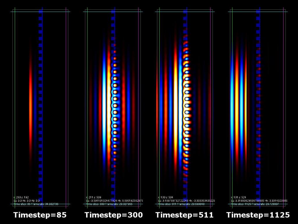
22 22


23 Waveguide Coating Simulations Computed parameters that would allow for 99.8% reflectivity, agrees with Jena work on waveguide coatings[1] TE Reflectivity TM Reflectivity No phase noise was seen due to waveguide coating displacement, for fundamental beam or higher order modes Max phase variation across wavefront 10 6 ±10 4 radians Uncertainty plots shows difference between reflected and incident power due to finite size of simulation domain [1] High reflectivity grating waveguide coatings for 1064 nm, Bunkowski 2006 s waveguide depth, g grating depth 23
24 Conclusion FFT s work, just need to be careful, consider using RS in certain cases Modal model works, just need to ensure you use enough modes Modal model and FFT are identical for all real world examples Seen one option for rigorously simulating complex structures using the FDTD FDTD code is available to anyone who wants to use/play with it! 24
25 and finished 25
Stable Laser Resonator Modeling: Mesh Parameter Determination and Empty Cavity Modeling
 Stable Laser Resonator Modeling: Mesh Parameter Determination and Empty Cavity Modeling Justin Mansell, Steve Coy, Kavita Chand, Steve Rose, Morris Maynard, and Liyang Xu MZA Associates Corporation jmansell@mza.com
Basic optics. Geometrical optics and images Interference Diffraction Diffraction integral. we use simple models that say a lot! more rigorous approach
 Basic optics Geometrical optics and images Interference Diffraction Diffraction integral we use simple models that say a lot! more rigorous approach Basic optics Geometrical optics and images Interference
E x Direction of Propagation. y B y
 x E x Direction of Propagation k z z y B y An electromagnetic wave is a travelling wave which has time varying electric and magnetic fields which are perpendicular to each other and the direction of propagation,
Coupling of surface roughness to the performance of computer-generated holograms
 Coupling of surface roughness to the performance of computer-generated holograms Ping Zhou* and Jim Burge College of Optical Sciences, University of Arizona, Tucson, Arizona 85721, USA *Corresponding author:
Supplementary Figure 1 Optimum transmissive mask design for shaping an incident light to a desired
 Supplementary Figure 1 Optimum transmissive mask design for shaping an incident light to a desired tangential form. (a) The light from the sources and scatterers in the half space (1) passes through the
Optical Design with Zemax for PhD
 Optical Design with Zemax for PhD Lecture : Physical Optics 06-03-3 Herbert Gross Winter term 05 www.iap.uni-jena.de Preliminary Schedule No Date Subject Detailed content.. Introduction 0.. Basic Zemax
Advanced modelling of gratings in VirtualLab software. Site Zhang, development engineer Lignt Trans
 Advanced modelling of gratings in VirtualLab software Site Zhang, development engineer Lignt Trans 1 2 3 4 Content Grating Order Analyzer Rigorous Simulation of Holographic Generated Volume Grating Coupled
Optics Vac Work MT 2008
 Optics Vac Work MT 2008 1. Explain what is meant by the Fraunhofer condition for diffraction. [4] An aperture lies in the plane z = 0 and has amplitude transmission function T(y) independent of x. It is
Chapter 38 Wave Optics (II)
") Chapter 38 Wave Optics (II) Initiation: Young s ideas on light were daring and imaginative, but he did not provide rigorous mathematical theory and, more importantly, he is arrogant. Progress: Fresnel,
Chapter 38 Wave Optics (II) Initiation: Young s ideas on light were daring and imaginative, but he did not provide rigorous mathematical theory and, more importantly, he is arrogant. Progress: Fresnel,
Supplementary Figure 1: Schematic of the nanorod-scattered wave along the +z. direction.
 Supplementary Figure 1: Schematic of the nanorod-scattered wave along the +z direction. Supplementary Figure 2: The nanorod functions as a half-wave plate. The fast axis of the waveplate is parallel to
Diffraction Diffraction occurs when light waves is passed by an aperture/edge Huygen's Principal: each point on wavefront acts as source of another
 Diffraction Diffraction occurs when light waves is passed by an aperture/edge Huygen's Principal: each point on wavefront acts as source of another circular wave Consider light from point source at infinity
DOING PHYSICS WITH MATLAB COMPUTATIONAL OPTICS
 DOING PHYSICS WITH MATLAB COMPUTATIONAL OPTICS RAYLEIGH-SOMMERFELD DIFFRACTION CROSS SHAPED APERTURES Ian Cooper School of Physics, University of Sydney ian.cooper@sydney.edu.au DOWNLOAD DIRECTORY FOR
Single Slit Diffraction
 Name: Date: PC1142 Physics II Single Slit Diffraction 5 Laboratory Worksheet Part A: Qualitative Observation of Single Slit Diffraction Pattern L = a 2y 0.20 mm 0.02 mm Data Table 1 Question A-1: Describe
Beam shaping based on intermediate zone diffraction of a micro-aperture
 Optica Applicata, Vol. XXXVIII, No. 3, 2008 Beam shaping based on intermediate zone diffraction of a micro-aperture DANYAN ZENG, ZHIJUN SUN * Department of Physics, Xiamen University, Xiamen 361005, China
Wave Phenomena Physics 15c. Lecture 19 Diffraction
 Wave Phenomena Physics 15c Lecture 19 Diffraction What We Did Last Time Studied interference > waves overlap Amplitudes add up Intensity = (amplitude) does not add up Thin-film interference Reflectivity
Analysis of Slanted Gratings for Lightguide Coupling
 Analysis of Slanted Gratings for Lightguide Coupling Abstract Slanted gratings are commonly used for coupling light into optical lightguides due to their high efficiency in a certain diffraction order.
Determining Wave-Optics Mesh Parameters for Modeling Complex Systems of Simple Optics
 Determining Wave-Optics Mesh Parameters for Modeling Complex Systems of Simple Optics Dr. Justin D. Mansell, Steve Coy, Liyang Xu, Anthony Seward, and Robert Praus MZA Associates Corporation Outline Introduction
Lecture 4. Physics 1502: Lecture 35 Today s Agenda. Homework 09: Wednesday December 9
 Physics 1502: Lecture 35 Today s Agenda Announcements: Midterm 2: graded soon» solutions Homework 09: Wednesday December 9 Optics Diffraction» Introduction to diffraction» Diffraction from narrow slits»
High spatial resolution measurement of volume holographic gratings
 High spatial resolution measurement of volume holographic gratings Gregory J. Steckman, Frank Havermeyer Ondax, Inc., 8 E. Duarte Rd., Monrovia, CA, USA 9116 ABSTRACT The conventional approach for measuring
Phase. E = A sin(2p f t+f) (wave in time) or E = A sin(2p x/l +f) (wave in space)
 (wave in time) or E = A sin(2p x/l +f) (wave in space)") Interference When two (or more) waves arrive at a point (in space or time), they interfere, and their amplitudes may add or subtract, depending on their frequency and phase. 1 Phase E = A sin(2p f t+f)
Interference When two (or more) waves arrive at a point (in space or time), they interfere, and their amplitudes may add or subtract, depending on their frequency and phase. 1 Phase E = A sin(2p f t+f)
Module 18: Diffraction-I Lecture 18: Diffraction-I
 Module 18: iffraction-i Lecture 18: iffraction-i Our discussion of interference in the previous chapter considered the superposition of two waves. The discussion can be generalized to a situation where
FRESNEL DIFFRACTION AND PARAXIAL WAVE EQUATION. A. Fresnel diffraction
 19 IV. FRESNEL DIFFRACTION AND PARAXIAL WAVE EQUATION A. Fresnel diffraction Any physical optical beam is of finite transverse cross section. Beams of finite cross section may be described in terms of
Effective Medium Theory, Rough Surfaces, and Moth s Eyes
 Effective Medium Theory, Rough Surfaces, and Moth s Eyes R. Steven Turley, David Allred, Anthony Willey, Joseph Muhlestein, and Zephne Larsen Brigham Young University, Provo, Utah Abstract Optics in the
Chapter 3 Geometric Optics
 Chapter 3 Geometric Optics [Reading assignment: Goodman, Fourier Optics, Appendix B Ray Optics The full three dimensional wave equation is: (3.) One solution is E E o ûe i ωt± k r ( ). This is a plane
Efficient wave-optical calculation of 'bad systems'
 1 Efficient wave-optical calculation of 'bad systems' Norman G. Worku, 2 Prof. Herbert Gross 1,2 25.11.2016 (1) Fraunhofer Institute for Applied Optics and Precision Engineering IOF, Jena, Germany (2)
Lesson 1 Scattering, Diffraction, and Radiation
 Lesson 1 Scattering, Diffraction, and Radiation Chen-Bin Huang Department of Electrical Engineering Institute of Photonics Technologies National Tsing Hua University, Taiwan Various slides under courtesy
ECEG105/ECEU646 Optics for Engineers Course Notes Part 5: Polarization
 ECEG105/ECEU646 Optics for Engineers Course Notes Part 5: Polarization Prof. Charles A. DiMarzio Northeastern University Fall 2008 Sept 2008 11270-05-1 Wave Nature of Light Failure of Raytracing Zero-λ
Lenses lens equation (for a thin lens) = (η η ) f r 1 r 2
 = (η η ) f r 1 r 2") Lenses lens equation (for a thin lens) 1 1 1 ---- = (η η ) ------ - ------ f r 1 r 2 Where object o f = focal length η = refractive index of lens material η = refractive index of adjacent material r 1
Lenses lens equation (for a thin lens) 1 1 1 ---- = (η η ) ------ - ------ f r 1 r 2 Where object o f = focal length η = refractive index of lens material η = refractive index of adjacent material r 1
Chapter 36. Diffraction. Copyright 2014 John Wiley & Sons, Inc. All rights reserved.
 Chapter 36 Diffraction Copyright 36-1 Single-Slit Diffraction Learning Objectives 36.01 Describe the diffraction of light waves by a narrow opening and an edge, and also describe the resulting interference
Using a multipoint interferometer to measure the orbital angular momentum of light
 CHAPTER 3 Using a multipoint interferometer to measure the orbital angular momentum of light Recently it was shown that the orbital angular momentum of light can be measured using a multipoint interferometer,
Diffraction, Fourier Optics and Imaging
 Diffraction, Fourier Optics and Imaging Diffraction, Fourier Optics and Imaging OKAN K. ERSOY WILEY-INTERSCIENCE A JOHN WILEY & SONS, INC., PUBLICATION Copyright # 2007 by John Wiley & Sons, Inc. All
Second Year Optics 2017 Problem Set 1
 Second Year Optics 2017 Problem Set 1 Q1 (Revision of first year material): Two long slits of negligible width, separated by a distance d are illuminated by monochromatic light of wavelength λ from a point
Physical & Electromagnetic Optics: Basic Principles of Diffraction
 24/06/2017 Physical & Electromagnetic Optics: Basic Principles of Diffraction Optical Engineering Prof. Elias N. Glytsis School of Electrical & Computer Engineering National Technical University of Athens
WORCESTER POLYTECHNIC INSTITUTE
 WORCESTER POLYTECHNIC INSTITUTE MECHANICAL ENGINEERING DEPARTMENT Optical Metrology and NDT ME-593L, C 2018 Introduction: Wave Optics January 2018 Wave optics: coherence Temporal coherence Review interference
dq dt I = Irradiance or Light Intensity is Flux Φ per area A (W/m 2 ) Φ =
 Φ =") Radiometry (From Intro to Optics, Pedrotti -4) Radiometry is measurement of Emag radiation (light) Consider a small spherical source Total energy radiating from the body over some time is Q total Radiant
Radiometry (From Intro to Optics, Pedrotti -4) Radiometry is measurement of Emag radiation (light) Consider a small spherical source Total energy radiating from the body over some time is Q total Radiant
Contrast Optimization: A faster and better technique for optimizing on MTF ABSTRACT Keywords: INTRODUCTION THEORY
 Contrast Optimization: A faster and better technique for optimizing on MTF Ken Moore, Erin Elliott, Mark Nicholson, Chris Normanshire, Shawn Gay, Jade Aiona Zemax, LLC ABSTRACT Our new Contrast Optimization
OPTI-521 Graduate Report 2 Matthew Risi Tutorial: Introduction to imaging, and estimate of image quality degradation from optical surfaces
 OPTI-521 Graduate Report 2 Matthew Risi Tutorial: Introduction to imaging, and estimate of image quality degradation from optical surfaces Abstract The purpose of this tutorial is to introduce the concept
Numerical Study of Grating Coupler for Beam Steering. Wei Guo
 Numerical Study of Grating Coupler for Beam Steering by Wei Guo A thesis submitted in partial fulfillment of the requirements for the degree of Master of Science in Engineering (Automotive Systems Engineering)
THE UNIVERSITY OF NEW SOUTH WALES SCHOOL OF PHYSICS EXAMINATION - NOVEMBER 2009 PHYS ADVANCED OPTICS
 THE UNIVERSITY OF NEW SOUTH WALES SCHOOL OF PHYSICS EXAMINATION - NOVEMBER 2009 PHYS3060 - ADVANCED OPTICS Time allowed - 2 hours Total number of questions - 4 Attempt ALL questions The questions are of
Lecture 6. Dielectric Waveguides and Optical Fibers. Slab Waveguide, Modes, V-Number Modal, Material, and Waveguide Dispersions
 Lecture 6 Dielectric Waveguides and Optical Fibers Slab Waveguide, Modes, V-Number Modal, Material, and Waveguide Dispersions Step-Index Fiber, Multimode and Single Mode Fibers Numerical Aperture, Coupling
OPTICAL PROPAGATION METHODS FOR SYSTEM-LEVEL MODELING OF OPTICAL MEM SYSTEMS. Timothy P. Kurzweg
 OPTICAL PROPAGATION METHODS FOR SYSTEM-LEVEL MODELING OF OPTICAL MEM SYSTEMS by Timothy P. Kurzweg B.S. in E. E., The Pennsylvania State University, 1994 M.S. in E. E., University of Pittsburgh, 1997 Submitted
Experiment 8 Wave Optics
 Physics 263 Experiment 8 Wave Optics In this laboratory, we will perform two experiments on wave optics. 1 Double Slit Interference In two-slit interference, light falls on an opaque screen with two closely
Ray Optics I. Last time, finished EM theory Looked at complex boundary problems TIR: Snell s law complex Metal mirrors: index complex
 Phys 531 Lecture 8 20 September 2005 Ray Optics I Last time, finished EM theory Looked at complex boundary problems TIR: Snell s law complex Metal mirrors: index complex Today shift gears, start applying
Building the Future of Optical Modeling and Design
 SIOM, Lecture Series Building the Future of Optical Modeling and Design Frank Wyrowski Friedrich-Schiller-University, Professor LightTrans GmbH, President Jena, Germany frank.wyrowski@uni-jena.de Lecture
Class 11 Introduction to Surface BRDF and Atmospheric Scattering. Class 12/13 - Measurements of Surface BRDF and Atmospheric Scattering
 University of Maryland Baltimore County - UMBC Phys650 - Special Topics in Experimental Atmospheric Physics (Spring 2009) J. V. Martins and M. H. Tabacniks http://userpages.umbc.edu/~martins/phys650/ Class
Electricity & Optics
 Physics 24100 Electricity & Optics Lecture 27 Chapter 33 sec. 7-8 Fall 2017 Semester Professor Koltick Clicker Question Bright light of wavelength 585 nm is incident perpendicularly on a soap film (n =
A Diagonal Split-cell Model for the High-order Symplectic FDTD Scheme
 PIERS ONLINE, VOL. 2, NO. 6, 2006 715 A Diagonal Split-cell Model for the High-order Symplectic FDTD Scheme Wei Sha, Xianliang Wu, and Mingsheng Chen Key Laboratory of Intelligent Computing & Signal Processing
Lecture 16 Diffraction Ch. 36
 Lecture 16 Diffraction Ch. 36 Topics Newtons Rings Diffraction and the wave theory Single slit diffraction Intensity of single slit diffraction Double slit diffraction Diffraction grating Dispersion and
FRED Slit Diffraction Application Note
 FRED Slit Diffraction Application Note The classic problem of diffraction through a slit finds one of its chief applications in spectrometers. The wave nature of these phenomena can be modeled quite accurately
INTRODUCTION REFLECTION AND REFRACTION AT BOUNDARIES. Introduction. Reflection and refraction at boundaries. Reflection at a single surface
 Chapter 8 GEOMETRICAL OPTICS Introduction Reflection and refraction at boundaries. Reflection at a single surface Refraction at a single boundary Dispersion Summary INTRODUCTION It has been shown that
Michelson Interferometer
 Michelson Interferometer The Michelson interferometer uses the interference of two reflected waves The third, beamsplitting, mirror is partially reflecting ( half silvered, except it s a thin Aluminum
DOING PHYSICS WITH MATLAB COMPUTATIONAL OPTICS
 DOING PHYSICS WITH MATLAB COMPUTATIONAL OPTICS RAYLEIGH-SOMMERFELD DIFFRACTION RECTANGULAR APERTURES Ian Cooper School of Physics, University of Sydney ian.cooper@sydney.edu.au DOWNLOAD DIRECTORY FOR MATLAB
Measurement of Highly Parabolic Mirror using Computer Generated Hologram
 Measurement of Highly Parabolic Mirror using Computer Generated Hologram Taehee Kim a, James H. Burge b, Yunwoo Lee c a Digital Media R&D Center, SAMSUNG Electronics Co., Ltd., Suwon city, Kyungki-do,
Diffraction and Interference
 Diffraction and Interference Kyle Weigand, Mark Hillstrom Abstract: We measure the patterns produced by a CW laser near 650 nm passing through one and two slit apertures with a detector mounted on a linear
Modeling Focused Beam Propagation in scattering media. Janaka Ranasinghesagara
 Modeling Focused Beam Propagation in scattering media Janaka Ranasinghesagara Teaching Objectives Understand the need of focused beam computational models. Understand the concepts, equations and principles
Diffraction. Light bends! Diffraction assumptions. Solution to Maxwell's Equations. The far-field. Fraunhofer Diffraction Some examples
 Diffraction Light bends! Diffraction assumptions Solution to Maxwell's Equations The far-field Fraunhofer Diffraction Some examples Diffraction Light does not always travel in a straight line. It tends
Chapter 37. Interference of Light Waves
 Chapter 37 Interference of Light Waves Wave Optics Wave optics is a study concerned with phenomena that cannot be adequately explained by geometric (ray) optics These phenomena include: Interference Diffraction
Matthew Schwartz Lecture 19: Diffraction and resolution
 Matthew Schwartz Lecture 19: Diffraction and resolution 1 Huygens principle Diffraction refers to what happens to a wave when it hits an obstacle. The key to understanding diffraction is a very simple
Aberrations in Holography
 Aberrations in Holography D Padiyar, J Padiyar 1070 Commerce St suite A, San Marcos, CA 92078 dinesh@triple-take.com joy@triple-take.com Abstract. The Seidel aberrations are described as they apply to
dq dt I = Irradiance or Light Intensity is Flux Φ per area A (W/m 2 ) Φ =
 Φ =") Radiometry (From Intro to Optics, Pedrotti -4) Radiometry is measurement of Emag radiation (light) Consider a small spherical source Total energy radiating from the body over some time is Q total Radiant
Radiometry (From Intro to Optics, Pedrotti -4) Radiometry is measurement of Emag radiation (light) Consider a small spherical source Total energy radiating from the body over some time is Q total Radiant
d has a relationship with ψ
 Principle of X-Ray Stress Analysis Metallic materials consist of innumerable crystal grains. Each grain usually faces in a random direction. When stress is applied on such materials, the interatomic distance
Chapter 37. Wave Optics
 Chapter 37 Wave Optics Wave Optics Wave optics is a study concerned with phenomena that cannot be adequately explained by geometric (ray) optics. Sometimes called physical optics These phenomena include:
mywbut.com Diffraction
 Diffraction If an opaque obstacle (or aperture) is placed between a source of light and screen, a sufficiently distinct shadow of opaque (or an illuminated aperture) is obtained on the screen.this shows
Engineered Diffusers Intensity vs Irradiance
 Engineered Diffusers Intensity vs Irradiance Engineered Diffusers are specified by their divergence angle and intensity profile. The divergence angle usually is given as the width of the intensity distribution
PHYSICS. Chapter 33 Lecture FOR SCIENTISTS AND ENGINEERS A STRATEGIC APPROACH 4/E RANDALL D. KNIGHT
 PHYSICS FOR SCIENTISTS AND ENGINEERS A STRATEGIC APPROACH 4/E Chapter 33 Lecture RANDALL D. KNIGHT Chapter 33 Wave Optics IN THIS CHAPTER, you will learn about and apply the wave model of light. Slide
Assignment 8 Due November 29, Problems
 Assignment 8 Due November 29, 2011 Text readings Fresnel equations, chapter 4.6 Polarization, chapter 8, sections 1, 2, 3, 5, 6, 7, and 8. Problems Problem 1 Polarization by Reflection: Given a polarizer
Chapter 8 Optics for Engineers
 Chapter 8 Optics for Engineers Charles A. DiMarzio Northeastern University Sept. 22 Diffraction Collimated Beam: Divergence in Far Field Focused Beam: Minimum Spot Size and Location α = C λ D Sept. 22
Tutorial: Instantaneous Measurement of M 2 Beam Propagation Ratio in Real-Time
 Tutorial: Instantaneous Measurement of M 2 Beam Propagation Ratio in Real-Time By Allen M. Cary, Jeffrey L. Guttman, Razvan Chirita, Derrick W. Peterman, Photon Inc A new instrument design allows the M
DIFFRACTION 4.1 DIFFRACTION Difference between Interference and Diffraction Classification Of Diffraction Phenomena
 4.1 DIFFRACTION Suppose a light wave incident on a slit AB of sufficient width b, as shown in Figure 1. According to concept of rectilinear propagation of light the region A B on the screen should be uniformly
Applications of Piezo Actuators for Space Instrument Optical Alignment
 Year 4 University of Birmingham Presentation Applications of Piezo Actuators for Space Instrument Optical Alignment Michelle Louise Antonik 520689 Supervisor: Prof. B. Swinyard Outline of Presentation
Fundamental Optics for DVD Pickups. The theory of the geometrical aberration and diffraction limits are introduced for
 Chapter Fundamental Optics for DVD Pickups.1 Introduction to basic optics The theory of the geometrical aberration and diffraction limits are introduced for estimating the focused laser beam spot of a
PROCEEDINGS OF SPIE. Simulation of lateral color for a hybrid refractive-diffractive eyepiece by field tracing methods
 PROCEEDINGS OF SPIE SPIEDigitalLibrary.org/conference-proceedings-of-spie Simulation of lateral color for a hybrid refractive-diffractive eyepiece by field tracing methods D. Batte, M. Kuhn, F. Wyrowski
specular diffuse reflection.
 Lesson 8 Light and Optics The Nature of Light Properties of Light: Reflection Refraction Interference Diffraction Polarization Dispersion and Prisms Total Internal Reflection Huygens s Principle The Nature
PY212 Lecture 25. Prof. Tulika Bose 12/3/09. Interference and Diffraction. Fun Link: Diffraction with Ace Ventura
 PY212 Lecture 25 Interference and Diffraction Prof. Tulika Bose 12/3/09 Fun Link: Diffraction with Ace Ventura Summary from last time The wave theory of light is strengthened by the interference and diffraction
Spherical Microphone Arrays
 Spherical Microphone Arrays Acoustic Wave Equation Helmholtz Equation Assuming the solutions of wave equation are time harmonic waves of frequency ω satisfies the homogeneous Helmholtz equation: Boundary
Waves & Oscillations
 Physics 42200 Waves & Oscillations Lecture 37 Interference Spring 2016 Semester Matthew Jones Multiple Beam Interference In many situations, a coherent beam can interfere with itself multiple times Consider
Diffraction: Propagation of wave based on Huygens s principle.
 Diffraction: In addition to interference, waves also exhibit another property diffraction, which is the bending of waves as they pass by some objects or through an aperture. The phenomenon of diffraction
Determining Wave-Optics Mesh Parameters for Complex Optical Systems
 Copyright 007 Society of Photo-Optical Instrumentation Engineers. This paper was published in SPIE Proc. Vol. 6675-7 and is made available as an electronic reprint with permission of SPIE. One print or
Winter College on Optics in Environmental Science February Adaptive Optics: Introduction, and Wavefront Correction
 2018-23 Winter College on Optics in Environmental Science 2-18 February 2009 Adaptive Optics: Introduction, and Wavefront Correction Love G. University of Durham U.K. Adaptive Optics: Gordon D. Love Durham
Specification of Diffraction Orders for Grating Regions
 Specification of Diffraction Orders for Grating Regions Abstract For the configuration of waveguide layouts VirtualLab offers the waveguide component. Within this component it is possible to define an
Formulas of possible interest
 Name: PHYS 3410/6750: Modern Optics Final Exam Thursday 15 December 2011 Prof. Bolton No books, calculators, notes, etc. Formulas of possible interest I = ɛ 0 c E 2 T = 1 2 ɛ 0cE 2 0 E γ = hν γ n = c/v
Lecture Notes on Wave Optics (04/23/14) 2.71/2.710 Introduction to Optics Nick Fang
 2.71/2.710 Introduction to Optics Nick Fang") .7/.70 Introduction to Optics Nic Fang Outline: Fresnel Diffraction The Depth of Focus and Depth of Field(DOF) Fresnel Zones and Zone Plates Holography A. Fresnel Diffraction For the general diffraction
.7/.70 Introduction to Optics Nic Fang Outline: Fresnel Diffraction The Depth of Focus and Depth of Field(DOF) Fresnel Zones and Zone Plates Holography A. Fresnel Diffraction For the general diffraction
COHERENCE AND INTERFERENCE
 COHERENCE AND INTERFERENCE - An interference experiment makes use of coherent waves. The phase shift (Δφ tot ) between the two coherent waves that interfere at any point of screen (where one observes the
Fiber Optic Communication Systems. Unit-03: Properties of Light. https://sites.google.com/a/faculty.muet.edu.pk/abdullatif
 Unit-03: Properties of Light https://sites.google.com/a/faculty.muet.edu.pk/abdullatif Department of Telecommunication, MUET UET Jamshoro 1 Refractive index Department of Telecommunication, MUET UET Jamshoro
Manual Diffraction. Manual remote experiment Project e-xperimenteren+ J. Snellenburg, J.M.Mulder
 Manual remote experiment Project e-xperimenteren+ J. Snellenburg, J.M.Mulder 30-01-006 Colofon Manual diffraction Manual remote experiment Project e-xperimenteren+ Stichting Digitale Universiteit Oudenoord
MEFT / Quantum Optics and Lasers. Suggested problems from Fundamentals of Photonics Set 1 Gonçalo Figueira
 MEFT / Quantum Optics and Lasers Suggested problems from Fundamentals of Photonics Set Gonçalo Figueira. Ray Optics.-3) Aberration-Free Imaging Surface Determine the equation of a convex aspherical nonspherical)
1 Laboratory #4: Division-of-Wavefront Interference
 1051-455-0073, Physical Optics 1 Laboratory #4: Division-of-Wavefront Interference 1.1 Theory Recent labs on optical imaging systems have used the concept of light as a ray in goemetrical optics to model
HFAN Rev.1; 04/08
 pplication Note: HFN-0.0. Rev.; 04/08 Laser Diode to Single-Mode Fiber Coupling Efficienc: Part - Butt Coupling VILBLE Laser Diode to Single-Mode Fiber Coupling Efficienc: Part - Butt Coupling Introduction
Chapter 36. Diffraction. Dr. Armen Kocharian
 Chapter 36 Diffraction Dr. Armen Kocharian Diffraction Light of wavelength comparable to or larger than the width of a slit spreads out in all forward directions upon passing through the slit This phenomena
MEASUREMENT OF THE WAVELENGTH WITH APPLICATION OF A DIFFRACTION GRATING AND A SPECTROMETER
 Warsaw University of Technology Faculty of Physics Physics Laboratory I P Irma Śledzińska 4 MEASUREMENT OF THE WAVELENGTH WITH APPLICATION OF A DIFFRACTION GRATING AND A SPECTROMETER 1. Fundamentals Electromagnetic
Lasers PH 645/ OSE 645/ EE 613 Summer 2010 Section 1: T/Th 2:45-4:45 PM Engineering Building 240
 Lasers PH 645/ OSE 645/ EE 613 Summer 2010 Section 1: T/Th 2:45-4:45 PM Engineering Building 240 John D. Williams, Ph.D. Department of Electrical and Computer Engineering 406 Optics Building - UAHuntsville,
An Intuitive Explanation of Fourier Theory
 An Intuitive Explanation of Fourier Theory Steven Lehar slehar@cns.bu.edu Fourier theory is pretty complicated mathematically. But there are some beautifully simple holistic concepts behind Fourier theory
Use of the surface PSD and incident angle adjustments to investigate near specular scatter from smooth surfaces
 Use of the surface PSD and incident angle adjustments to investigate near specular scatter from smooth surfaces Kashmira Tayabaly a, John C. Stover b, Robert E. Parks a,c, Matthew Dubin a, James H. Burge*
College Physics 150. Chapter 25 Interference and Diffraction
 College Physics 50 Chapter 5 Interference and Diffraction Constructive and Destructive Interference The Michelson Interferometer Thin Films Young s Double Slit Experiment Gratings Diffraction Resolution
Optical Diffraction and Interference using Single Photon Counting
 Optical Diffraction and Interference using Single Photon Counting Optical Diffraction and Interference using Single Photon Counting In this experiment the wave and quantum properties of light can be studied
UNIT VI OPTICS ALL THE POSSIBLE FORMULAE
 58 UNIT VI OPTICS ALL THE POSSIBLE FORMULAE Relation between focal length and radius of curvature of a mirror/lens, f = R/2 Mirror formula: Magnification produced by a mirror: m = - = - Snell s law: 1
Exploiting scattering media for exploring 3D objects
 Exploiting scattering media for exploring 3D objects Alok Kumar Singh 1, Dinesh N Naik 1,, Giancarlo Pedrini 1, Mitsuo Takeda 1, 3 and Wolfgang Osten 1 1 Institut für Technische Optik and Stuttgart Research
11.0 Measurement of Spindle Error Motion
 11.0 Measurement of Spindle Error Motion 11.1 Introduction The major spindle error motion is caused by the alignment of the spindle rotational axis, the centerline of the tool holder and the centerline
Physical & Electromagnetic Optics: Diffraction Gratings
 31/05/2018 Physical & Electromagnetic Optics: Diffraction Gratings Optical Engineering Prof. Elias N. Glytsis School of Electrical & Computer Engineering National Technical University of Athens Multiple
Today: Interferometry, Diffraction
 Physics 228 Please check list of students w/o registered iclicker! Today: Interferometry, Diffraction Diffraction is a further expansion of the idea of interference: Instead of two sources we consider