Certification by Analysis
|
|
|
- Barrie Gregory
- 5 years ago
- Views:
Transcription

1 Certification by Analysis Gerardo Olivares June 16 th, 2008


2 Certification by Analysis Motivation and Key Issues Aircraft manufacturers are under strong pressure to reduce costs and development cycles. The development of aircraft interiors is driven by individualized customer demands, increasingly complex products and ever shorter innovation cycles. To remain competitive in today s market, aircraft manufacturers must conduct research in the development of state-of-the-art computational tools and processes in order to reduce the amount of physical testing, certification costs and product development cycles. Objective Provide a document of best practices so that Industry and FAA personnel can gain an understanding of the fundamental modeling methods, develop an appreciation of the modeling problem areas, and limitations of current numerical models. Technical Approach Phase I Numerical ATD / Phase II Seat Structure/Materials 2
3 FAA Sponsored Project Information Principal Investigators & Researchers G.Olivares PhD, PI K. S. Raju PhD (High Strain Rate Material Testing) J. Guarddon, S. Patrick, V. Yadav FAA Technical Monitor Allan Abramowitz Other FAA Personnel Involved Rick Dewesse (CAMI) David Moorcroft (CAMI) Industry Participation Weber Aircraft, Contour Seating,B/E Aerospace, SICMA, Schroth Safety Products, AMSAFE, TASS/TNO-MADYMO, Altair-Radioss, FTSS, ESI-Pamcrash, MSC, Cessna, Airbus NA, Hawker/Beechcraft, SAE Seat Committee 3
4 AC Scope This document defines the acceptable applications, limitations, validation processes, and minimum documentation requirements involved when substantiation by computer modeling is used to support a seat certification program. Computer modeling analytical techniques may be used to do the following, provided all pass/fail criteria identified in , , , or are satisfied: Establish the critical seat installation/configuration in preparation for dynamic testing. Demonstrate compliance to , , , or for changes to a baseline seat design, where the baseline seat design has demonstrated compliance to these rules by dynamic tests. Changes may include geometric or material changes to primary and non-primary structure. 4

![II [ 30 Sled Tests]) Test variability studies Establish corridors for validation](/docs-images/87/95102158/images/5-2.jpg "criteria ATD Validation reference database Validation criteria: Validation metrics")


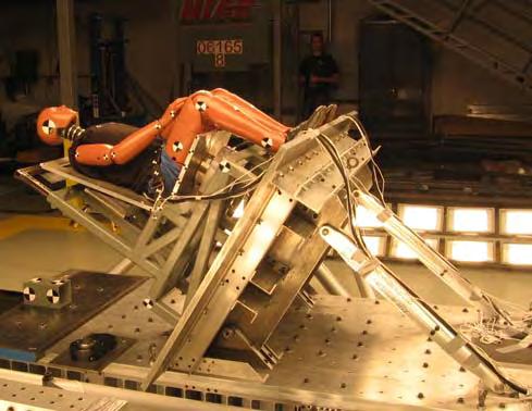
5 Certification by Analysis I Phase I: Numerical Anthropometric Test Dummies: Literature review and numerical tools survey Sled testing Rigid Seat (Series I [23 Sled Test] and II [ 30 Sled Tests]) Test variability studies Establish corridors for validation criteria ATD Validation reference database Validation criteria: Validation metrics methods: review and evaluation Identify data channels required, and tolerance levels for model validation Simulation studies: Survey numerical ATD database availability Preliminary evaluation of numerical ATDs with sled test data for part and dynamic requirements Stochastic and/or DOE numerical model evaluation Comparison HII vs. HIII FAA ATD performance 5


6 NIAR Sled Series 1 Numerical ATD Validation Reference Data TEST NUMBER ATD Serial# BELT TYPE TEST ANGLE (deg) LOADING SEAT TYPE BELT MATERIAL CRASH PULSE FAA HYB III g Rigid 100% Polyester FAA HYB III g Rigid 100% Polyester HYB II g Rigid 100% Polyester HYB II g Rigid 100% Polyester HYB II g Rigid 100% Polyester HYB II g Rigid 100% Polyester FAA HYB III g Rigid 100% Polyester FAA HYB III g Rigid 100% Polyester EMPTY g Rigid HYB II g Rigid 100% Polyester HYB II g Rigid 100% Polyester FAA HYB III g Rigid 100% Polyester FAA HYB III g Rigid 100% Polyester FAA HYB III g Rigid 100% Polyester FAA HYB III g Rigid 100% Polyester EMPTY g Rigid HYB II g Rigid 100% Polyester HYB II g Rigid 100% Polyester * HYB II g Cushioned 100% Polyester HYB II g Cushioned 100% Polyester FAA HYB III g Cushioned 100% Polyester FAA HYB III g Cushioned 100% Polyester ** FAA HYB III g Cushioned 100% Polyester


7 NIAR Sled Series 2 Numerical ATD Validation Reference Data SAE ARP 5765 TEST NUMBER ATD BELT TYPE TEST ANGLE (deg) LOADING SEAT TYPE BELT MATERIAL CRASH PULSE HYB II g Rigid 100% Nylon HYB II g Rigid 100% Nylon HYB II g Rigid 100% Nylon HYB II g Rigid 100% Nylon HYB II g Rigid 100% Nylon HYB II g Rigid 100% Nylon HYB II g Rigid 100% Nylon HYB II g Rigid 100% Nylon HYB II g Rigid 100% Nylon HYB II g Rigid 100% Nylon HYB II g Rigid 100% Nylon HYB II g Rigid 100% Nylon FAA HYB III g Rigid 100% Nylon FAA HYB III g Rigid 100% Nylon FAA HYB III g Rigid 100% Nylon FAA HYB III g Rigid 100% Nylon FAA HYB III g Rigid 100% Nylon FAA HYB III g Rigid 100% Nylon FAA HYB III g Rigid 100% Nylon FAA HYB III g Rigid 100% Nylon FAA HYB III g Rigid 100% Nylon FAA HYB III g Rigid 100% Nylon FAA HYB III g Rigid 100% Nylon FAA HYB III g Rigid 100% Nylon FAA HYB III g Rigid 100% Nylon HYB II g Rigid 100% Nylon HYB II g Rigid 100% Nylon HYB II g Rigid 100% Nylon HYB II g Rigid 100% Nylon


8 FAR **.562: Emergency Landing Conditions 8


9 Test Data Channels and Polarities Overview Channel Description Channel Units Hybrid II Hybrid III Sled acceleration G's vs Sec Head X acceleration G's vs Sec Head Y acceleration G's vs Sec Head Z acceleration G's vs Sec Upper neck force X direction Lbf vs Sec Upper neck force Y direction Lbf vs Sec Upper neck force Z direction Lbf vs Sec Upper neck moment about X axis In-lbf vs Sec Upper neck moment about Y axis In-lbf vs Sec Upper neck moment about Z axis In-lbf vs Sec Torso X acceleration G's vs Sec Torso Y acceleration G's vs Sec Torso Z acceleration G's vs Sec Lumbar load X direction Lbf vs Sec Lumbar load Z direction Lbf vs Sec Lumbar moment about Y axis In-lbf vs Sec Pelvis X acceleration G's vs Sec Pelvis Y acceleration G's vs Sec Pelvis Z acceleration G's vs Sec Left femur compression load Lbf vs Sec Right femur compression load Lbf vs Sec Lap strap left side tension load Lbf vs Sec Lap strap right side tension load Lbf vs Sec Shoulder left strap tension load Lbf vs Sec Shoulder right strap tension load Lbf vs Sec Joint shoulder straps tension load Lbf vs Sec Seat back X reaction force Lbf vs Sec Seat back Y reaction force Lbf vs Sec Seat back Z reaction force Lbf vs Sec Seat pan X reaction force Lbf vs Sec Seat pan Y reaction force Lbf vs Sec Seat pan Z reaction force Lbf vs Sec Seat pan X reaction moment In-lbf vs Sec Seat pan Y reaction moment In-lbf vs Sec Seat pan Z reaction moment In-lbf vs Sec Head trajectory in the X-Z plane Inch vs Inch Chest trajectory in the X-Z plane Inch vs Inch Torso trajectory in the X-Z plane Inch vs Inch Knee trajectory in the X-Z plane Inch vs Inch SAE J
10 Validation Metrics Computable measures are needed that can quantitatively compare experimental and computational results over a series of parameters to objectively assess computational accuracy over the traditional qualitative graphical comparison Applications: Quantify repeatability of test results (Establish physical test variability corridors) Numerical model quality evaluation Four validation metrics methods currently under evaluation: Sprague & Geers validation metric Weighted Integration Factor validation metric Quick Rating from MADPost Software (includes 3 different metric evaluations) Mod Eval Software (includes 4 different metric evaluations) Relative Error method Quantitative vs. Qualitative Methods Magnitude Error Phase Error Area Under Curve Error 10
11 Validation Metric Selection The following error metrics will be defined in SAE ARP 5765: Magnitude Error using Relative Error Shape Error using Sprague and Geers The error metric for motion data is different for Magnitude Error using a simple difference error metric on the most significant peak Since these metrics compare only two sets of data and there are three sets to compare, the following method is used: Test 1 vs test 2 = Δ1 Test 1 vs test 3 = Δ2 Test 2 vs test 3 = Δ3 The highest value from Δ1 through Δ3 is used Note that the biasing of these metrics do not have a significant effect on the results when the errors are small; thus, for test data uncertainty measurement, it does not have a considerable influence in what order the curves are compared since errors are generally small 11
12 Validation Metric Shape Error (Sprague & Geers) ϑ ϑ ϑ bb cc bc = = = t t t 2 Where; t t 1 t t 1 b t 1 1 t t 2 1 t t 1 c ( t) dt ( t) dt b( t) c( t) dt P M = 1 1 cos π ( ϑ bc = ϑcc bb / / ϑ 1 ϑ bb ϑ cc ) Peak Magnitude 2 C = M + P 2 t1<t<t2 evaluation period b(t) = reference data c(t) = data to compare P = phase error M = magnitude error C = shape error (S&G score) Peak Phasing Evaluation Period Shape 12
13 Validation Metric Peak Magnitude Error Relative Error Metrics used for Magnitude Error (accelerations and forces): Mag. Error (%) = Maxg( t) Maxf ( t) Maxf ( t) Maxf(t) = Peak or maximum magnitude value (positive or negative) in reference data Maxg(t) = Peak or maximum magnitude value (positive or negative) in candidate solution or data to compare Simple Difference used for Magnitude Error (Motion data only): Peak Magnitude Shape Mag. Error = Maxg(t) Maxf(t) Peak Phasing Evaluation Period 13

14 Validation Metric - Evaluation Period Configuration NIAR Sled Series Accelerometer Signals Load Cell Signals Position 2 Point Restraint - 0 degree HII 175 ms 200 ms 175 ms 3 Point Restraint - 0 degree HII 180 ms 180 ms 180 ms 4 Point Restraint - 0 degree HII 150 ms 150 ms 150 ms 2 Point Restraint - 60 degree HII 125 ms 125 ms 125 ms 2 Point Restraint - 0 degree HII 175 ms 200 ms 175 ms 3 Point Restraint - 0 degree HII 180 ms 180 ms 180 ms 4 Point Restraint - 0 degree HII 150 ms 150 ms 150 ms 2 Point Restraint - 60 degree HII 125 ms 125 ms 125 ms Peak Magnitude Peak Phasing Shape Evaluation Period 14


15 Example Error Metric Test Data HII 2 Point Belt Configuration Sled Ax Head Ax Head Ay Head Az Head Ar Torso Ax Torso Ay Torso Az Torso Ar Pelvic Ax Pelvic Ay Pelvic Az Pelvic Ar Left Femur Right Femur Left Lap H2 2pt 0deg 16g Mag. Error Shape Error Mag. Error Shape Error 3% 2% Right Lap 5% 6% 7% 23% Lumbar Fx 16% 11% 102% 86% Lumbar Fz 7% 9% 18% 7% Lumbar My 21% 9% 19% 7% Seat Back Fx 3% 8% 47% 29% Seat Back Fy 36% 65% 19% 65% Seat Back Fz 35% 24% 8% 14% Seat Pan Fx 18% 11% 8% 15% Seat Pan Fy 61% 77% 18% 16% Seat Pan Fz 17% 13% 16% 59% Seat Pan Res 18% 12% 21% 23% Seat Pan Mx 39% 77% 15% 15% Seat Pan My 12% 10% 5% 14% Seat Pan Mz 98% 121% 66% 18% Head CG X Excursion 1 2% 6% 2% Head CG Z Excursion 1 1% 15

16 Example Error Metric Test Data HII 2 Point Belt Configuration HII ATD COMPLIANCE RESPONSES (0º 2 POINT BELT TESTS) ERROR 20% 18% 16% 14% 12% 10% 8% 6% 4% 2% 0% Head Ar Lumbar Fz Left Lap Right Lap Seat Pan Res CHANNEL Mag. Error Phase Error 16
17 Conclusions CBA Phase I Reference Sled Tests completed and available to numerical ATD developers and SAE ARP 5765 working group. Validated HII and HIII FAA numerical models will be available at the end of the year from all the major FE and Multibody Solvers. HII and HIII FAA test repeatability studies completed ([2, 3 and 4 point restraints] [0 and 60 deg Test Conditions] [ Dynamic conditions FAR and ]) Data will be published in CBA Phase I FAA report. Validation metrics and validation criteria will be defined in SAE ARP Develop testing protocols and data requirements to validate computer models. Plans to propose addendum to AC or to include protocol in ARP Data will be published in CBA Phase I FAA report. Comparison of HII and HIII FAA performance for typical aerospace applications will be published CBA Phase I in FAA report.[2, 3 and 4 point restraints] [0 and 60 deg Test Conditions] [ Dynamic conditions FAR and ]. 17
18 Certification by Analysis II Phase II: Aerospace Seat Material Modeling Requirements and Material Database: Literature review: Material data, testing protocols Survey of materials used in aerospace seating applications Review of material data required for numerical analysis: Material Models: Structural components, cushions, and webbing Strain rate definition for typical structural components Computational FE Studies for various aerospace seat configurations Experimental Studies for various aerospace seat configurations Test repeatability Comparison studies with computational solutions Component Testing Protocols: Metallic components, seat cushions, and belt webbing Material Database: Physical testing // Component Testing Variability Validation material models: Physical Testing vs. Simulation 18
19 Material Survey: Aluminums ALUMINUM Material Designation Material Form Material Specification 7075 T6 Sheet AMS-4045 AMS-QQ-A-250/12 Rolled/Drawn Bar AMS-QQ-A 225/9 Extrusion Bar AMS-QQ-A 200/ T651 Plate AMS T3 Sheet AMS-4037 AMS-QQ-A-250/4 Rolled/Drawn Bar AMS-4086 AMS-QQ-A-225/6 Extrusion Bar AMS-QQ-A-200/ T351 Rolled/Drawn Bar AMS-4120 Plate AMS T3511 Extrusion Bar AMS T6 Sheet AMS-4029 Bar AMS T651 Plate AMS T6 Rolled/Drawn Bar AMS T6511 Extrusion Bar AMS-QQ-A-200/ T6 Sheet BS EN T6 Plate BS EN T6 Extrusion Tube BS EN L114 T6 Tube BS L114(1971) L168 T6 Bar BS L168(1978) 5251 H22 Sheet BS EN
20 Material Survey: Steels STEEL Material Designation Material Form Material Specification AISI 4130 Tube AMS 6361 AMS-T-6736 Bar AMS-S PH Bar AMS 5643 (H900, H1025, H1150) S-154 Bar BS 154(1976) X2CrNi19-11, , C or Sheet BS EN H(304S11) C30E, , +N(080M30) Bar BS EN Sheet BS EN


21 Strain Rate Specifications - Development Process Strain rate: 0.45 Strain rate:2.18 Strain rate: 5.3 Strain rate: 1.4 Strain rate: Material Database 21
. Two repetitions: FAR 25.")
22 Reference Test : Seat Type A Four Dynamic Tests will be conducted with a typical aircraft seat configuration: Two repetitions: FAR deg no pitch, roll or yaw (Note one baseline test is completed). Two repetitions: FAR deg Purpose: Identify strain rate range for various seat components Baseline comparison with FE simulation model Physical testing repeatability studies 22
23 Reference Computational Model: FE Model Overview Detail finite element model seat structure and occupants. Purpose: Define strain gauge locations and instrumentation for physical testing Identify strain rate for various seat components Baseline comparison with physical system Numerical model predictability Study numerical model accuracy with quasi-static material data 23


24 Plastic Deformation - Identify Strain Gauge Location and Orientation X X X X

25 Reference Sled Test Data Channels FAR Pulse # Channels Channel Description Channel Units 1 Sled acceleration G's vs Sec 3 Head X acceleration G's vs Sec 3 Head Y acceleration G's vs Sec 3 Head Z acceleration G's vs Sec 3 Torso X acceleration G's vs Sec 3 Torso Y acceleration G's vs Sec 3 Torso Z acceleration G's vs Sec 3 Lumbar load X direction Lbf vs Sec 3 Lumbar load Z direction Lbf vs Sec 3 Lumbar moment about Y axis In-lbf vs Sec 3 Pelvis X acceleration G's vs Sec 3 Pelvis Y acceleration G's vs Sec 3 Pelvis Z acceleration G's vs Sec 3 Lap strap left side tension load Lbf vs Sec 3 Lap strap right side tension load Lbf vs Sec 4 Floor Attachments X interface loads Lbf vs Sec 4 Floor Attachments Y interface loads Lbf vs Sec 4 Floor Attachments Z interface loads Lbf vs Sec 34 Strain Gauges Strain vs Sec Head trajectory in the X-Z plane Inch vs Inch 4 Torso trajectory in the X-Z plane Inch vs Inch Knee trajectory in the X-Z plane Inch vs Inch a 2b


26 Reference Sled Test Sample Instrumentation Gauge #1 Gauge #2 Gauge #25 RIGHT SEAT CENTER SEAT LEFT SEAT 26


27 Comparison Simulation and Sled Test - Kinematics Front Top Left Of. 27


28 Comparison Simulation and Sled Test Floor Loads 28


29 Comparison Simulation and Sled Test Strain and Strain Rate Strain rate bellow 1 /s Data analysis ongoing 29


30 Configuration II: FAR Test I 30


31 Configuration II: ATD Kinematics Left Of. 31


32 Configuration II: Strain Gauge Locations for Physical Testing Element ID: Max. Strain: Element ID: Max. Strain: Element ID: Max. Strain: Element ID: Max. Strain: Element ID: Max. Strain: Element ID:97992 Max. Strain: Element ID:97002 Max. Strain: Element ID: Max. Strain: Element ID: Max. Strain: Strain rate bellow 12 /s Data analysis ongoing 32


33 FE Modeling Study Seat Type II 33

34 FE Study II: Belt Webbing Testing Load Vs Displacement 6 in/min Ramp Up- 6 in/min test #3 Ramp Down - 6 in/min test #3 Ramp Up- 6 in/min test #4 Ramp Down- 6 in/min test # Load Vs Displacement 0.25 in/min Ramp Up in/min test #1 Ramp Down in/min test #1 Ramp Up-0.25 in/min test #2 Ramp Down in/min test #2 Axial Load (lbf) Axial Load (lbf) Axial Disp (in) Tabs Axial Disp (in) 2.5 GAUGE LENGTH
 test")

35 FE Study II: Seat Cushion Testing Note: Quasi-static an dynamic (30 in/sec) test procedures as described in Aircraft Seat Cushion Component Testing document DOT/FAA/AR-05/5 35


36 FE Study II: FAR


37 FE Study II: ATD Kinematics Left Of. 37
38 FE Study II: ATD Accelerometer Data 38
39 FE Study II: Load Cell Data 39
40 Conclusions CBA Phase II Four types of seats (2 an 3 place coach seats, first class seat and a business jet seat) have been analyzed for FAR Type II (no pitch roll or yaw) condition: Strain rates do not exceed 1.0 /s [ Testing and simulation 3 place coach seat] Further numerical analysis with pitch, roll and yaw is ongoing Three types of seats have been analyzed for FAR Type I condition: Strain rates do not exceed 12.0 /s [Based on simulation] Physical testing preparation ongoing Define recommended testing protocols for: Seat Cushion Testing quasi static and dynamic testing Metallic component material testing quasi static and high strain rate testing Seat Belt Webbing Testing Test repeatability studies for a typical aircraft seat installation is ongoing. This data may be used to establish correlation levels for AC and/or ARP Material list for typical aluminums and steels has been defined. Quasi-static material data parameters required for simulation models are available in MIL HBK 5 for most of these materials. 40


41 Future Work Joints and fittings modeling techniques Modeling fastener pre-loads Predictive component failure modeling: Component level Seat assembly level Numerical ATD initial positioning methods Numerical seat model pitch and roll procedures Numerical seat model permanent deformations Non-deterministic seat modeling evaluation. Based on component test variability. Installation evaluations: Row-to-row configuration Bulkhead configuration Seat cushion replacement Prepare CBA Industry workshops 41
42 A Look Forward Benefit to Aviation: Reduce certification costs Reduce development cycles Improve product design (Passenger Safety and Weight Reduction) Provide data for ongoing SAE Aerospace Recommended Practice ARP 5765 on CBA Provide a simulation industry standard Future needs: Typical joints and fittings modeling guidelines: Component Testing, Failure Models, Modeling Techniques System level computational Stochastic and DOE analyses: Eliminate deterministic models and designs hence improving the robustness of the designs Research additional applications such as row-to-row, bulkhead, HUD and OHU installations, and side facing seats Develop Virtual Certification protocols 42
Disclaimer for FAA Research Publication
 Disclaimer for FAA Research Publication Although the FAA has sponsored this project, it neither endorses nor rejects the findings of the research. The presentation of this information is in the interest
Crashworthiness Certification by Analysis: Numerical Model Preparation and Analysis Guidelines
 Crashworthiness Certification by Analysis: Numerical Model Preparation and Analysis Guidelines Gerardo Olivares Certification by Analysis Motivation and Key Issues Physical testing certification costs
Certification by Analysis I and II
 Certification by Analysis I and II Gerardo Olivares May 20 th 2010 CBA I Research Program Overview Phase I: HII and HIII FAA Numerical ATD Validation [July 2005 - July 2010]: Test variability HII and HIII
Development of Detailed AM50%ile Hybrid III Dummy FE Model
 Development of Detailed AM50%ile Hybrid III Dummy FE Model Presented at LS-DYNA Forum, 13 October 2011, Filderstadt (Stuttgart), Germany TOYOTA MOTOR CORPORATION Tatsuya KOMAMURA 1/21 CONTENTS 1. Background
Simplified FE Simulation of Frontal Occupant Restraint Systems
 7 th European LS-DYNA Conference Simplified FE Simulation of Frontal Occupant Restraint Systems Richard Brown, David Coleman, Ian Bruce Jaguar Land Rover, Coventry, UK. Arup, Solihull, UK. Summary: The
Numerical Simulation of Aircraft Seat Compliance Test using LS-DYNA Implicit Solver
 Numerical Simulation of Aircraft Seat Compliance Test using LS-DYNA Implicit Solver Satish Pathy LSTC, Livermore, CA Thomas Borrvall DYNAmore Nordic AB, Linköping, Sweden Abstract With the possibility
Tutorial 9: Simplified truck model with dummy, airbag and seatbelt
 Tutorial 9 Simplified Truck Model with Dummy and Airbag Problem description Outline Analysis type(s): Element type(s): Materials law(s): Model options: Key results: Prepared by: Date: Version: Frontal
Development of MADYMO Models of Passenger Vehicles for Simulating Side Impact Crashes
 SAE TECHNICAL PAPER SERIES 1999-01-2885 Development of MADYMO Models of Passenger Vehicles for Simulating Side Impact Crashes B. R. Deshpande, T. J. Gunasekar, V. Gupta and S. Jayaraman EASi S. M. Summers
Development of a Methodology for Simulating Seat Back Interaction Using Realistic Body Contours
 Development of a Methodology for Simulating Seat Back Interaction Using Realistic Body Contours Jingwen Hu Matthew P. Reed Biosciences Group April 16, 2013 Introduction Dimensional mismatch between a seat
WP5 - Computational Mechanics Acceleration transducers on Finite Element vehicle models for crash simulations with Ls-Dyna
 ROBUST PROJECT Department of Aerospace engineering* - Politecnico di Milano Volume 1 of 1 (*)via La Masa, 34 Milan-ITALY tel: +39 2 23998316 - fax: +39 2 23998334 Jan 25 Doc. No.: ROBUST-5-7 - Rev. Pagei
CODE Product Solutions
 CODE Product Solutions Simulation Innovations Glass Fiber Reinforced Structural Components for a Group 1 Child Harold van Aken About Code Product Solutions Engineering service provider Specialised in Multiphysics
Investigation of seat modelling for sled analysis and seat comfort analysis with J-SEATdesigner
 Investigation of seat modelling for sled analysis and seat comfort analysis with J-SEATdesigner Noriyo ICHINOSE 1, Hideki YAGI 1 1 JSOL Corporation, Nagoya, Japan 1 Abstract Recently vehicle model is becoming
George Scarlat 1, Sridhar Sankar 1
 Development Methodology for a New Finite Element Model of the WorldSID 50 th percentile Male Side Impact Dummy George Scarlat 1, Sridhar Sankar 1 Abstract This paper describes the modeling and validation
Efficiency Improvement of Seat Belt Pull CAE Analysis by Technology and Process Changes
 Efficiency Improvement of Seat Belt Pull CAE Analysis by Technology and Process Changes Ligong Pan, Sushanth Ramavath, Seung Hyun Jung, Luis Hernandez, Randall Frank Core CAE Methods, Digital Innovation,
Technical Bulletin Data format and Injury Criteria Calculation Version 1.1 June 2015 TB 021
 Technical Bulletin Data format and Injury Criteria Calculation June 2015 TB 021 Copyright 2015 Euro NCAP - This work is the intellectual property of Euro NCAP. Permission is granted for this material to
EFFECT OF AIRCRAFT SEAT BELT MODELING TECHNIQUES ON THE CRASH DYNAMICS AND INJURY CRITERIA FOR A HYBRID III 50 TH PERCENTILE FAA DUMMY.
 EFFECT OF AIRCRAFT SEAT BELT MODELING TECHNIQUES ON THE CRASH DYNAMICS AND INJURY CRITERIA FOR A HYBRID III 50 TH PERCENTILE FAA DUMMY A Thesis by Amit A. Deshpande Bachelors of Engineering, Pune University,
AGATE (ADVANCED GENERAL AVIATION TRANSPORTATION EXPERIMENTS PROGRAM)
") AGATE (ADVANCED GENERAL AVIATION TRANSPORTATION EXPERIMENTS PROGRAM) METHODOLOGY FOR SEAT DESIGN AND CERTIFICATION BY ANALYSIS (REVISION A) AGATE-WP3.4-034012-079-REPORT SUBMITTED BY CESSNA AIRCRAFT COMPANY
AGATE (ADVANCED GENERAL AVIATION TRANSPORTATION EXPERIMENTS PROGRAM) METHODOLOGY FOR SEAT DESIGN AND CERTIFICATION BY ANALYSIS (REVISION A) AGATE-WP3.4-034012-079-REPORT SUBMITTED BY CESSNA AIRCRAFT COMPANY
Design of a Precision Robot Wrist Interface. Patrick Willoughby Advisor: Alexander Slocum MIT Precision Engineering Research Group
 Design of a Precision Robot Wrist Interface Patrick Willoughby Advisor: Alexander Slocum MIT Precision Engineering Research Group Project Summary Problem: Current bolted robot wrist replacements are inaccurate,
Dummy model validation and its assessment
 Dummy model validation and its assessment Sebastian Stahlschmidt, Alexander Gromer, Yupeng Huang DYNAmore GmbH, Germany 25 th January 2012 1 Introduction The design of occupant safety systems by using
Using Computer Aided Engineering Processes in Packaging Design Development
 Using Computer Aided Engineering Processes in Packaging Design Development Jose Martinez, Miguel Angel Garcia Jose Luis Moreno Vicencio & Hugo Miranda Mabe, Mexico Mahesh Patel, Andrew Burkhalter, Eric
Simulating Seat Back Interaction Using Realistic Body Contours
 Simulating Seat Back Interaction Using Realistic Body Contours Matthew P. Reed Jingwen Hu Biosciences Group Introduction Dimensional mismatch between a seat and sitter can cause discomfort. Traditional
Appendix A - Figures. A 2 Chestband contours for the twelve cases (a) A-pillar (b) B-pillar (c) C-pillar
 A-pillar (b) B-pillar (c) C-pillar") Appendix A - Figures A 1 GHBMC model at t=0 ms (a) with no belt tightening (b) with belt tightening; seat belt hidden for displacement contour visibility A 2 Chestband contours for the twelve cases (a)
Appendix A - Figures A 1 GHBMC model at t=0 ms (a) with no belt tightening (b) with belt tightening; seat belt hidden for displacement contour visibility A 2 Chestband contours for the twelve cases (a)
Correlation of the Federal Motor Vehicle Safety Standard 225 (FMVSS225) Requirement of an Automotive Seat System Using LS-DYNA
 Requirement of an Automotive Seat System Using LS-DYNA") 7 th International LS-DYNA Users Conference Simulation Technology (2) Correlation of the Federal Motor Vehicle Safety Standard 225 (FMVSS225) Requirement of an Automotive Seat System Using LS-DYNA Frank
7 th International LS-DYNA Users Conference Simulation Technology (2) Correlation of the Federal Motor Vehicle Safety Standard 225 (FMVSS225) Requirement of an Automotive Seat System Using LS-DYNA Frank
Crew Module Water Landing Simulation Methods Development for NASA
 Crew Module Water Landing Simulation Methods Development for NASA Mahesh Patel Engineering Manager, Altair ProductDesign Inc 38 Executive Park, Suite 200, Irvine, CA, 92614 4709, USA mahesh@altairpd.com
Comparison of Human Body Model and PMHS Occupant Kinematic Response in Laboratory Rollover Tests
 Comparison of Human Body Model and PMHS Occupant Kinematic Response in Laboratory Rollover Tests Jack R. Cochran 1, Qi Zhang 1, and Jason R. Kerrigan 1 1 Department of Mechanical and Aerospace Engineering,
Tutorial 1: Welded Frame - Problem Description
 Tutorial 1: Welded Frame - Problem Description Introduction In this first tutorial, we will analyse a simple frame: firstly as a welded frame, and secondly as a pin jointed truss. In each case, we will
IMPROVED SIF CALCULATION IN RIVETED PANEL TYPE STRUCTURES USING NUMERICAL SIMULATION
 26 th ICAF Symposium Montréal, 1 3 June 2011 IMPROVED SIF CALCULATION IN RIVETED PANEL TYPE STRUCTURES USING NUMERICAL SIMULATION S.C. Mellings 1, J.M.W. Baynham 1 and T.J. Curtin 2 1 C.M.BEASY, Southampton,
Experimental Methods in Crash and Impact for Simulation Validation
 Experimental Methods in Crash and Impact for Simulation Validation FAA Workshop on Use of Dynamic Analysis Methods in Aircraft Certification Blacksburg, VA 10-11 August 2016 Rory Bigger (rory.bigger@swri.org)
Altair HTC09 Ludwigsburg 2nd-4th November 2009
 Altair HTC09 Ludwigsburg 2nd-4th November 2009 Analysis with RADIOSS of a bird strike onto a helicopter blade and onto a rotor control chain Francesca Bianchi INTRODUCTION The demostration that bird strike
Simulation of Overhead Crane Wire Ropes Utilizing LS-DYNA
 Simulation of Overhead Crane Wire Ropes Utilizing LS-DYNA Andrew Smyth, P.E. LPI, Inc., New York, NY, USA Abstract Overhead crane wire ropes utilized within manufacturing plants are subject to extensive
SDC. Engineering Analysis with COSMOSWorks. Paul M. Kurowski Ph.D., P.Eng. SolidWorks 2003 / COSMOSWorks 2003
 Engineering Analysis with COSMOSWorks SolidWorks 2003 / COSMOSWorks 2003 Paul M. Kurowski Ph.D., P.Eng. SDC PUBLICATIONS Design Generator, Inc. Schroff Development Corporation www.schroff.com www.schroff-europe.com
A multi-body systems approach to simulate helicopter occupant protection systems Vadlamudi, S., Blundell, M.V. and Zhang, Y.
 A multi-body systems approach to simulate helicopter occupant protection systems Vadlamudi, S., Blundell, M.V. and Zhang, Y. Author post-print (accepted) deposited in CURVE May 2012 Original citation &
Finite Element Simulation using SPH Particles as Loading on Typical Light Armoured Vehicles
 10 th International LS-DYNA Users Conference Penetration / Blast Finite Element Simulation using SPH Particles as Loading on Typical Light Armoured Vehicles Geneviève Toussaint and Robert Durocher Defence
SUPPORTING LINEAR MOTION: A COMPLETE GUIDE TO IMPLEMENTING DYNAMIC LOAD SUPPORT FOR LINEAR MOTION SYSTEMS
 SUPPORTING LINEAR MOTION: A COMPLETE GUIDE TO IMPLEMENTING DYNAMIC LOAD SUPPORT FOR LINEAR MOTION SYSTEMS Released by: Keith Knight Catalyst Motion Group Engineering Team Members info@catalystmotiongroup.com
EDR Report Information
 EDR Report File Information Value VIN 5YJXCDE20HF041782 Retrieval Date 2017/06/30 02:16:00 (UTC) Retrieval User Comments Retrieval Program Information EDR Report Information Tesla EDR Reporting Service
Connection Elements and Connection Library
 Connection Elements and Connection Library Lecture 2 L2.2 Overview Introduction Defining Connector Elements Understanding Connector Sections Understanding Connection Types Understanding Connector Local
SHAPE OPTIMIZATION FOR HEAD AND KNEE IMPACT FEATURING ADAPTIVE MESH TOPOLOGY AND A DISCRETE VARIABLE
 SHAPE OPTIMIZATION FOR HEAD AND KNEE IMPACT FEATURING ADAPTIVE MESH TOPOLOGY AND A DISCRETE VARIABLE Nielen Stander, Mike Burger, Suri Balasubramanyam Livermore Software Technology Corporation, Livermore
Automotive Testing: Optical 3D Metrology Improves Safety and Comfort
 Automotive Testing: Optical 3D Metrology Improves Safety and Comfort GOM Measuring System: ARAMIS, TRITOP, GOM Touch Probe Keywords: Automotive, Crash Testing, Static and Dynamic Deformation, Simulation
IDENTIFYING WORST CASE DESIGNS THROUGH A COMBINED STRATEGY OF COMPUTATIONAL MODELING, STATISTICAL METHODS, AND BENCH TOP TESTS
 IDENTIFYING WORST CASE DESIGNS THROUGH A COMBINED STRATEGY OF COMPUTATIONAL MODELING, STATISTICAL METHODS, AND BENCH TOP TESTS Payman Afshari Andrew Dooris Pat Fatyol DePuy Synthes Spine, a Johnson and
Increasing Machine Service Life of Large Envelope, High Acceleration AFP Machines
 2013-01-2297 Published 09/17/2013 Copyright 2013 SAE International doi:10.4271/2013-01-2297 saeaero.saejournals.org Increasing Machine Service Life of Large Envelope, High Acceleration AFP Machines Justin
USE OF STOCHASTIC ANALYSIS FOR FMVSS210 SIMULATION READINESS FOR CORRELATION TO HARDWARE TESTING
 7 th International LS-DYNA Users Conference Simulation Technology (3) USE OF STOCHASTIC ANALYSIS FOR FMVSS21 SIMULATION READINESS FOR CORRELATION TO HARDWARE TESTING Amit Sharma Ashok Deshpande Raviraj
Fluid-structure Interaction by the mixed SPH-FE Method with Application to Aircraft Ditching
 Fluid-structure Interaction by the mixed SPH-FE Method with Application to Aircraft Ditching Paul Groenenboom ESI Group Delft, Netherlands Martin Siemann German Aerospace Center (DLR) Stuttgart, Germany
Principal Roll Structure Design Using Non-Linear Implicit Optimisation in Radioss
 Principal Roll Structure Design Using Non-Linear Implicit Optimisation in Radioss David Mylett, Dr. Simon Gardner Force India Formula One Team Ltd. Dadford Road, Silverstone, Northamptonshire, NN12 8TJ,
Dummy Model Validation and its Assessment
 12 th International LS-DYNA Users Conference Occupant Safety Dummy Model Validation and its Assessment Sebastian Stahlschmidt, Alexander Gromer, Yupeng Huang, Uli Franz DYNAmore GmbH Industriestr. 2 70563
LIGO Scissors Table Static Test and Analysis Results
 LIGO-T980125-00-D HYTEC-TN-LIGO-31 LIGO Scissors Table Static Test and Analysis Results Eric Swensen and Franz Biehl August 30, 1998 Abstract Static structural tests were conducted on the LIGO scissors
Modeling Trajectories of Human Volunteers in Low-Speed Frontal Impacts Using Bézier Curves
 Modeling Trajectories of Human Volunteers in Low-Speed Frontal Impacts Using Bézier Curves M. Samuels 1,2,3, T. Seacrist 2, M. P. Reed 4, K. B. Arbogast 2,5 1 Brigham Young University 2 Center for Injury
Modeling Strategies for Dynamic Finite Element Cask Analyses
 Session A Package Analysis: Structural Analysis - Modeling Modeling Strategies for Dynamic Finite Element Cask Analyses Uwe Zencker, Günter Wieser, Linan Qiao, Christian Protz BAM Federal Institute for
Development of special new versions of the FAT/PDB Dummy models for quick analysis response. The Rapid Analysis Models (R.A.M.).
.") Development of special new versions of the FAT/PDB Dummy models for quick analysis response. The Rapid Analysis Models (R.A.M.). Reuben D Souza, Yupeng Huang, Sebastian Stahlschmidt DYNAmore GmbH, Stuttgart,
Development of special new versions of the FAT/PDB Dummy models for quick analysis response. The Rapid Analysis Models (R.A.M.). Reuben D Souza, Yupeng Huang, Sebastian Stahlschmidt DYNAmore GmbH, Stuttgart,
Orbital forming of SKF's hub bearing units
 Orbital forming of SKF's hub bearing units Edin Omerspahic 1, Johan Facht 1, Anders Bernhardsson 2 1 Manufacturing Development Centre, AB SKF 2 DYNAmore Nordic 1 Background Orbital forming is an incremental
Numerical Simulation of Elastic-Plastic Deformation of Aircraft Fuel Tank Access Cover Impacted by Tyre Fragment
 Numerical Simulation of Elastic-Plastic Deformation of Aircraft Fuel Tank Access Cover Impacted by Tyre Fragment Alexander A. Ryabov, Vladimir I. Romanov, Sergey S. Kukanov, Anatoliy K. Botvinkin Sarov
Influence of Pre-Stressed Parts in Dummy Modeling - Simple Considerations -
 8 th International LS-DYNA Users Conference Crash/Safety (2) Influence of Pre-Stressed Parts in Dummy Modeling - Simple Considerations - Ulrich Franz*, Peter Schuster**, Sebastian Stahlschmidt** *DYNAmore
Chapter 5. Creating GATB events involves the following basic steps:
 Chapter 5 GATB Tutorial This tutorial provides examples illustrating two common applications of GATB; occupant modeling and pedestrian modeling. Creating GATB events involves the following basic steps:
Documentation FAT LS-DYNA USSID 5.0. User s Manual Manual Release 1.0 for Model 5.0 January 8, DYNAmore GmbH
 Documentation FAT LS-DYNA USSID 5.0 User s Manual Manual Release 1.0 for Model 5.0 January 8, 2007 DYNAmore GmbH www.dynamore.de Germany Authors: Uli Franz Sebastian Stahlschmidt Bastian Keding Contact
Efficient Shape Optimisation of an Aircraft Landing Gear Door Locking Mechanism by Coupling Abaqus to GENESIS
 Efficient Shape Optimisation of an Aircraft Landing Gear Door Locking Mechanism by Coupling Abaqus to GENESIS Mark Arnold and Martin Gambling Penso Consulting Ltd GRM Consulting Ltd Abstract: The objective
Design Verification Procedure (DVP) Load Case Analysis of Car Bonnet
 Load Case Analysis of Car Bonnet") Design Verification Procedure (DVP) Load Case Analysis of Car Bonnet Mahesha J 1, Prashanth A S 2 M.Tech Student, Machine Design, Dr. A.I.T, Bangalore, India 1 Asst. Professor, Department of Mechanical
Design Verification Procedure (DVP) Load Case Analysis of Car Bonnet Mahesha J 1, Prashanth A S 2 M.Tech Student, Machine Design, Dr. A.I.T, Bangalore, India 1 Asst. Professor, Department of Mechanical
Simulation Driven Optimized Mechanism Drive
 Simulation Driven Optimized Mechanism Drive August 30, 2011 Elias Taye, PhD Wm Wrigley Jr. Company Subsidiary of Mars Inc. 1 AGENDA Introduction of Wm Wrigley Jr. Company Original Design of the Mechanical
SENSITIVITY OF PROJECTILE MUZZLE RESPONSES TO GUN BARREL CENTERLINE VARIATIONS. Michael M Chen
 23 RD INTERNATIONAL SYMPOSIUM ON BALLISTICS TARRAGONA, SPAIN 16-20 APRIL 2007 SENSITIVITY OF PROJECTILE MUZZLE RESPONSES TO GUN BARREL CENTERLINE VARIATIONS Michael M Chen US Army Research Laboratory,
Yaw-Roll Coupled Oscillations of a Slender Delta Wing
 Yaw-Roll Coupled Oscillations of a Slender Delta Wing John C. Worley * Auburn University Aerospace Engineering, Auburn, Alabama, 3683 Reported are the results of experiments conducted on a slender delta
Development of a Model of the Muscle Skeletal System using Adams. Its Application to an Ergonomic Study in Automotive Industry
 Copyright 2004 SAE International 2004-01-2169 Development of a Model of the Muscle Skeletal System using Adams. Its Application to an Ergonomic Study in Automotive Industry G. Esteves IST- UTL C. Ferreira,
Investigations of Generalized Joint Stiffness Model in LSTC Hybrid III Rigid-FE Dummies
 11 th International LS-DYNA Users Conference Automotive (3) Investigations of Generalized Joint Stiffness Model in LSTC Hybrid III Rigid-FE Dummies Shu Yang and Xuefeng Wang IMMI Abstract The joint restraint
WORK ORDER 7: Portable Sign Crash Test NUMERICAL MODELING INTERIM REPORT. Submitted To: The Pennsylvania Department of Transportation.
 WORK ORDER 7: Portable Sign Crash Test NUMERICAL MODELING INTERIM REPORT Submitted To: The Pennsylvania Department of Transportation February 2007 Pennsylvania Transportation Institute The Pennsylvania
In these areas, different numbers of points are defined which the FMH hits in free motion at a speed of 24 km/h.
 HEAD IMPACT PROTECTION - NEW REQUIREMENTS AND SOLUTIONS Michael Menking F. Porsche Porsche AG Germany Paper Number 9X-SS-O-06 ABSTRACT The NHTSA has very substantially extended its existing Part 571 -
2: Static analysis of a plate
 2: Static analysis of a plate Topics covered Project description Using SolidWorks Simulation interface Linear static analysis with solid elements Finding reaction forces Controlling discretization errors
Finite element representations of crash
 Optimization of Material Parameters for Crash Test Dummies George Scarlat Sridhar Sankar Simulia Corp. Providence, R.I. process automation and design optimization software makes it easier to identify optimal
SimWise. 3D Dynamic Motion, and Stress Analysis. integrated with Alibre Design
 SimWise 3D Dynamic Motion, and Stress Analysis integrated with Alibre Design SimWise 4D for Alibre Integrated Motion Simulation and Stress Analysis SimWise 4D is a software tool that allows the functional
Support Systems for Developing System Models
 Support Systems for Developing System Models Hasan G. Pasha, Karan Kohli, Randall J. Allemang, David L. Brown and Allyn W. Phillips University of Cincinnati Structural Dynamics Research Lab (UC-SDRL),
A Sensitivity Analysis On The Springback Behavior Of The Unconstrained Bending Problem
 A Sensitivity Analysis On The Springback Behavior Of The Unconstrained Bending Problem T. Meinders 1,2, A.W.A. Konter 1, S.E. Meijers 1, E.H. Atzema 3, H. Kappert 4 1 Netherlands Institute for Metals Research,
Advanced Finite Element Model for AE-MDB Side Impact Barrier
 Advanced Finite Element Model for AE-MDB Side Impact Barrier Authors: M. Asadi 1, P. Tattersall 1, B. Walker 2, H. Shirvani 3 1. Cellbond Composites Ltd. 2. ARUP Campus (UK) 3. Anglia Ruskin University
Revised Sheet Metal Simulation, J.E. Akin, Rice University
 Revised Sheet Metal Simulation, J.E. Akin, Rice University A SolidWorks simulation tutorial is just intended to illustrate where to find various icons that you would need in a real engineering analysis.
AXIAL OF OF THE. M. W. Hyer. To mitigate the. Virginia. SUMMARY. the buckling. circumference, Because of their. could.
 IMPROVEMENT OF THE AXIAL BUCKLING CAPACITY OF COMPOSITE ELLIPTICAL CYLINDRICAL SHELLS M. W. Hyer Department of Engineering Science and Mechanics (0219) Virginia Polytechnic Institute and State University
Explicit Dynamic Analysis of Bird Strike Simulations and Design Optimization of Composite Aircraft Structures
 Explicit Dynamic Analysis of Bird Strike Simulations and Design Optimization of Composite Aircraft Structures Manoj Susarla Jr Design Engineer Octants Engineering Innovations Dr no 12-3-25,Ayyevari street,
Background CE 342. Why RISA-2D? Availability
 Background CE 342 RISA-2D RISA-2D is a structural analysis program, which can model: Beams, frames, trusses and plates. Any linear elastic structural material. Typical supports, such as pins, rollers and
Lesson 1: Introduction to Pro/MECHANICA Motion
 Lesson 1: Introduction to Pro/MECHANICA Motion 1.1 Overview of the Lesson The purpose of this lesson is to provide you with a brief overview of Pro/MECHANICA Motion, also called Motion in this book. Motion
FEM (MSC.Nastran SOL600) and Multibody (MSC.Adams flexible contact) solutions: an application example in helicopter rotor analysis
 and Multibody (MSC.Adams flexible contact) solutions: an application example in helicopter rotor analysis") FEM (MSC.Nastran SOL6) and Multibody (MSC.Adams flexible contact) solutions: an application example in helicopter rotor analysis Daniele Catelani MSC. Software - EMEA Aerospace Consultant Francesca Bianchi
FEM (MSC.Nastran SOL6) and Multibody (MSC.Adams flexible contact) solutions: an application example in helicopter rotor analysis Daniele Catelani MSC. Software - EMEA Aerospace Consultant Francesca Bianchi
Commercial Vehicle Powertrain Mount Selection Based on Static and Modal Analysis Using Altair Motion-Solve
 Commercial Vehicle Powertrain Mount Selection Based on Static and Modal Analysis Using Altair Motion-Solve E.Loganathan Divisional manager Ashok Leyland Limited Vallur Chennai-600103 India Loganathan.e@ashokleyland.com
Impact of Complex System Behavior on Seismic Assessment of RC Bridges
 Impact of Complex System Behavior on Seismic Assessment of RC Bridges Amr S. Elnashai Department of Civil and Environmental Engineering Based on the PhD Work of Thomas Frankie, Advised by Kuchma, Spencer
Virtual Product Development for HCV -FUPD Structure
 Virtual Product Development for HCV -FUPD Structure Shailesh Kadre Principal CAE Analyst Mahindra Engineering Services #128/A, Sanghavi Compound, Chinchwad Pune, 411 018 Ravindra Kumar Senior CAE-Analyst
ACTUATING SYSTEMS BASED ON TWO BELLOWS
 ACTUATING SYSTEMS BASED ON TWO BELLOWS PhD Stud. Eng. Vasile Sergiu JIŞA, Technical University of Cluj-Napoca, e-mail: vasile_sergiu_jisa@yahoo.com Assist. PhD Eng. Beniamin CHETRAN, Technical University
LMS Virtual.Lab Noise and Vibration
 LMS Virtual.Lab Noise and Vibration LMS Virtual.Lab Noise and Vibration From component to system-level noise and vibration prediction 2 LMS Virtual.Lab Noise and Vibration LMS Virtual.Lab Noise and Vibration
Optimization to Reduce Automobile Cabin Noise
 EngOpt 2008 - International Conference on Engineering Optimization Rio de Janeiro, Brazil, 01-05 June 2008. Optimization to Reduce Automobile Cabin Noise Harold Thomas, Dilip Mandal, and Narayanan Pagaldipti
THE 3D LIGHTWEIGHT OPTIMIZATION FOR HIGH LOADED PARTS CASE STUDY
 6 th International Conference Computational Mechanics and Virtual Engineering COMEC 2015 15-16 October 2015, Braşov, Romania THE 3D LIGHTWEIGHT OPTIMIZATION FOR HIGH LOADED PARTS CASE STUDY Gabriel. D.
Failure of Notched Laminates Under Out-of- Plane Bending. Phase VI Technical Review John Parmigiani Oregon State University
 Failure of Notched Laminates Under Out-of- Plane Bending. Phase VI 2013 Technical Review John Parmigiani Oregon State University Failure of Notched Laminates Under Out-of-Plane Bending, all phases Motivation
Revision of the SolidWorks Variable Pressure Simulation Tutorial J.E. Akin, Rice University, Mechanical Engineering. Introduction
 Revision of the SolidWorks Variable Pressure Simulation Tutorial J.E. Akin, Rice University, Mechanical Engineering Introduction A SolidWorks simulation tutorial is just intended to illustrate where to
FINITE ELEMENT ANALYSIS (FEA) OF A C130 TOWING BAR
 OF A C130 TOWING BAR") FINITE ELEMENT ANALYSIS (FEA) OF A C130 TOWING BAR Fadzli Ibrahim* & Mohammad Shafiq Toha Mechanical & Aerospace Technology Division (BTJA), Science & Technology Research Institute for Defence (STRIDE),
FINITE ELEMENT ANALYSIS (FEA) OF A C130 TOWING BAR Fadzli Ibrahim* & Mohammad Shafiq Toha Mechanical & Aerospace Technology Division (BTJA), Science & Technology Research Institute for Defence (STRIDE),
Introduction. Section 3: Structural Analysis Concepts - Review
 Introduction In this class we will focus on the structural analysis of framed structures. Framed structures consist of components with lengths that are significantly larger than crosssectional areas. We
Simulation of AJWSP10033_FOLDED _ST_FR
 Phone: 01922 453038 www.hyperon-simulation-and-cad-services.co.uk Simulation of AJWSP10033_FOLDED _ST_FR Date: 06 May 2017 Designer: Study name: AJWSP10033_FOLDED_STATIC Analysis type: Static Description
AN ADVANCED 50TH PERCENTILE THOR DUMMY DATABASE
 AN ADVANCED 5TH PERCENTILE THOR DUMMY DATABASE Martinez, L. Vera, C. Lasaga, F. Garcia, M. Institute Universitario de lnvestigaci6n del Autom6vil, INSIA. UPM. Spain. ABSTRACT As part of the ADRIA project
Analysis of Fluid-Structure Interaction Effects of Liquid-Filled Container under Drop Testing
 Kasetsart J. (Nat. Sci.) 42 : 165-176 (2008) Analysis of Fluid-Structure Interaction Effects of Liquid-Filled Container under Drop Testing Chakrit Suvanjumrat*, Tumrong Puttapitukporn and Satjarthip Thusneyapan
Engineering Effects of Boundary Conditions (Fixtures and Temperatures) J.E. Akin, Rice University, Mechanical Engineering
 J.E. Akin, Rice University, Mechanical Engineering") Engineering Effects of Boundary Conditions (Fixtures and Temperatures) J.E. Akin, Rice University, Mechanical Engineering Here SolidWorks stress simulation tutorials will be re-visited to show how they
Engineering Effects of Boundary Conditions (Fixtures and Temperatures) J.E. Akin, Rice University, Mechanical Engineering Here SolidWorks stress simulation tutorials will be re-visited to show how they
NUMERICAL ANALYSIS OF ROLLER BEARING
 Applied Computer Science, vol. 12, no. 1, pp. 5 16 Submitted: 2016-02-09 Revised: 2016-03-03 Accepted: 2016-03-11 tapered roller bearing, dynamic simulation, axial load force Róbert KOHÁR *, Frantisek
17. SEISMIC ANALYSIS MODELING TO SATISFY BUILDING CODES
 17. SEISMIC ANALYSIS MODELING TO SATISFY BUILDING CODES The Current Building Codes Use the Terminology: Principal Direction without a Unique Definition 17.1 INTRODUCTION { XE "Building Codes" }Currently
Fast Tracking Rail Vehicle Design
 Fast Tracking Rail Vehicle Design Nigel Randell Senior Engineer Crash Safety, Bombardier Transportation UK Ltd Litchurch Lane, Derby, DE24 8AD, UK nigel.randell@uk.transport.bombardier.com Jérôme Rousseau
TOLERANCE ALLOCATION IN FLEXIBLE ASSEMBLIES: A PRACTICAL CASE
 TOLERANCE ALLOCATION IN FLEXIBLE ASSEMBLIES: A PRACTICAL CASE Pezzuti E., Piscopo G., Ubertini A., Valentini P.P. 1, Department of Mechanical Engineering University of Rome Tor Vergata via del Politecnico
Finite Element Method for Predicting the Behavior of Sandwich Structure Luggage Floor of Passenger Cars
 IOP Conference Series: Materials Science and Engineering PAPER OPEN ACCESS Finite Element Method for Predicting the Behavior of Sandwich Structure Luggage Floor of Passenger Cars To cite this article:
PTC Newsletter January 14th, 2002
 PTC Email Newsletter January 14th, 2002 PTC Product Focus: Pro/MECHANICA (Structure) Tip of the Week: Creating and using Rigid Connections Upcoming Events and Training Class Schedules PTC Product Focus:
Finite Element Modeling of Aluminium Honeycomb with Variable Crush Strength and Its Application in AE-MDB Model
 Finite Element Modeling of Aluminium Honeycomb with Variable Crush Strength and Its Application in AE-MDB Model M. Asadi 1, B. Walker 2, M. Ashmead 3, H. Mebrahtu 2, 1. Anglia Ruskin University (mehhrdad.asadi@anglia.ac.uk)
Three-Dimensional Child Anthropometry for Vehicle Safety Analysis. Matthew P. Reed Sheila M. Ebert-Hamilton Biosciences Group October 2012
 Three-Dimensional Child Anthropometry for Vehicle Safety Analysis Matthew P. Reed Sheila M. Ebert-Hamilton Biosciences Group October 2012 Children in Cars Data on the size, shape, and posture of children
Ideas on Applying Very Fine Models in Dummy Model Development
 10 th International LS-DYNA Users Conference Crash/Safety (1) Ideas on Applying Very Fine Models in Dummy Model Development Uli Franz 1, Alexander Gromer 1, Matthias Walz 2, Jens Zschieschack 1, Yupeng
Multi-Body Simulation of Earthmoving Equipment using MotionView / MotionSolve
 Multi-Body Simulation of Earthmoving Equipment using MotionView / MotionSolve Amit Srivastava Manager Larsen & Toubro IES Knowledge City, NH8 Vadodara 390 019, India Gopikrishnan. M Assistant Manager Larsen
Workshop 15. Single Pass Rolling of a Thick Plate
 Introduction Workshop 15 Single Pass Rolling of a Thick Plate Rolling is a basic manufacturing technique used to transform preformed shapes into a form suitable for further processing. The rolling process