EEL 4924 Electrical Engineering Design (Senior Design) Team Baudiophile. Wireless Headphones
|
|
|
- Noah Osborne
- 5 years ago
- Views:
Transcription
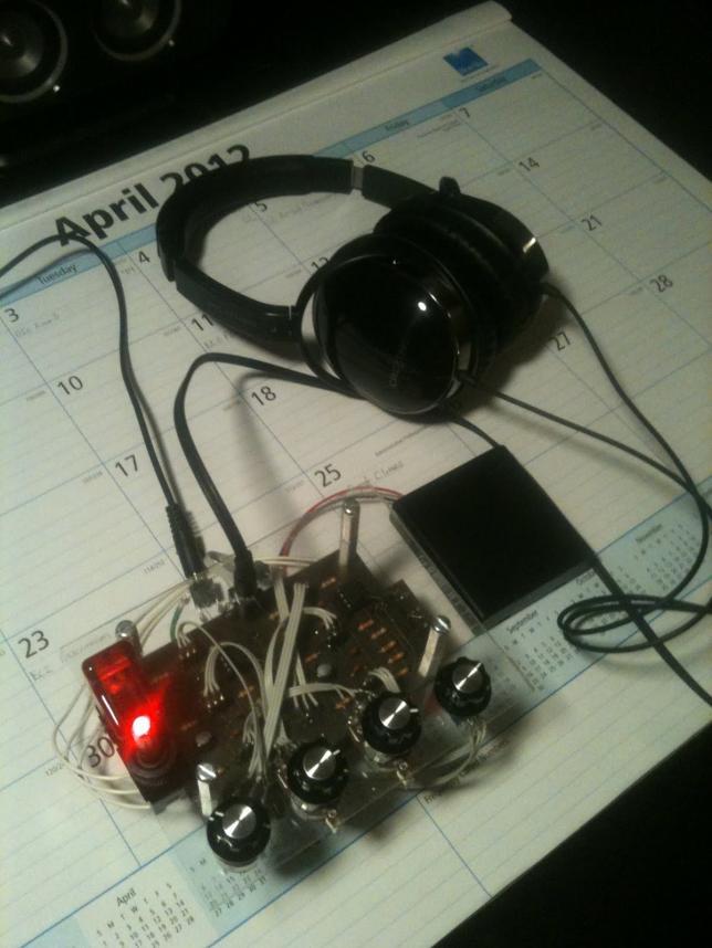
1 EEL 4924 Electrical Engineering Design (Senior Design) Final Design Report 25 April 2012 Team Baudiophile Wireless Headphones Team Members: Name: Stephen Brewer Name: Eli Chen Project Abstract Our project is a wireless headphone that utilizes a transmitter and receiver to wirelessly transmit audio signals to the user s headphones. Our system will have a transmitter unit on the audio source, and a portable, battery powered unit for the receiver where any 3.5 mm headphones may be plugged in. Wireless headphones will be useful for users who would like the freedom of moving around a room while listening to a TV or stationary mp3 player. 1
2 Table of Contents Project Features and Objectives...3 Cost Objective...4 Competing Product...5 Concept and Technology Selection...6 Flowcharts and Diagrams...7 Parts List...8 Separation of Work...9 Gannt Chart...10 Appendix A: Schematics...11 Appendix B: PCBs...14 Appendix C: Project Code...16 Appendix D: Equalizer Simulations
3 Project Features and Objectives The main objective for this project is to wirelessly and continuously transmit an audio signal to a pair of headphones. Our first objective is to establish a wireless link between our transmitter and receiver, and accurately send and receive an accurate digital data stream at at least 1.41 Mbps (uncompressed CD quality), without interference. We will use external audio A/D and D/A converters for the analog-digital conversion. Another design goal would be for the receiver to be small as well as low-power, using AA batteries. Estimated battery life of 200 hours Range of 40 yards LoS There will be several technical challenges. We would need our receiver unit to have an efficient low-power design for longer battery life and a better user experience. Another challenge would be in getting the microcontroller to process in the audio data outputted from a source and send the data in a compatible form to a transmitter at an acceptable data rate. The outcome is to have any headphones plugged into the receiver be able to clearly receive audio from the source of the transmitter, i.e. a ipod. The receiver will also include user input to change equalization and volume. 3

4 Cost Objective We re aiming to have the price of our wireless headphones be under $250. There are a few similar existing products available on the market that are rather expensive, so making the product with a lower price and better value is a goal that we have in mind. Unlike the existing products, which have everything built and packaged into a set of headphones, our product will be a packaged device in which the user can plug in any pair of preexisting headphones they own and start listening. Also, we are aiming to use a display for user input, where the user can change volume and equalizer settings. Similar products sold by Sony and Sennheiser currently cost between $120 and $300. 4

5 Competing Product, Sennheiser RS 170 Headphones, MSRP $
6 Concept and Technology Selection Most of the effort went into selecting the proper transceivers that would ensure accurate transmission of audio (stereo) data. In order for to do this, several factors need to be considered. The transceivers will need to be able to continuously transmit an audio stream to be received at a receiver end. The RF transceivers we are considering operate at 2.4GHz. In order to transmit uncompressed CD quality audio, 16 bits resolution at 44.1kHz sampling frequency is needed. This means that a 1.41Mbps rate is needed at a minimum for the specifications of the transceivers (not including overhead). Another factor is to have the transceiver consume as little power as possible, since the receiver will be used in a portable application. Also, to avoid overcomplication of the wireless portion of this project, the transceivers are purchased as a wireless module that has the transceiver and antenna on a PCB already, so that RF PCB design will not be necessary. Among our considerations were the Nordic nrf24l01+, nrf24z1 and various Zigbee transceivers. Nordic transceivers nrf24z1 were chosen, which operate at Mbps for LPCM audio in 2.4 GHz RF band. It also has a Quality of Service engine (QoS) that ensures audio quality, i.e. retransmitting lost packets. Other parts needed are ADC s and DAC s that can match the 44.1kHz sampling rate needed, 16 bit resolution, as well as having at least 2 channels to take in stereo input. Therefore, the WM8737 was chosen for the ADC, and the TLV320DAC23 was chosen for the DAC. The microcontroller chosen was an MSP430, which can control the transceivers and ADC/DAC. The digital portion functions off of 3.3V. Analog components will be needed to create an equalizer circuit. We want to be able to adjust the bass and treble independently for an optimized sound for the user. Cutoff frequencies for the 3 bands would be 100 Hz, 1kHz, and 10kHz. The analog portion functions off of 6V. A stereo headphone amplifier controls the volume. The headphone amplifier would need to be matched impedance-wise to a pair of headphones. There are 3.5mm headphone jacks both on the output of the receiver unit and the input of the transmitter unit. 6
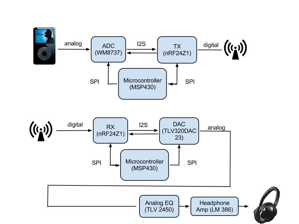
7 Flowcharts and Diagrams Block diagram 7

8 Parts List 2x Nordic nrf24z1 module 2x TI MSP430 1x WM8717 ADC 1x TLV320DAC23 DAC 2x TLV2450 2x LM386 Estimated build cost: ~$90 8
9 Separation of Work Eli Interface components together (ADC to transmitter, receiver to microcontroller to DAC) Establishing a consistent wireless link between the two tranceivers Microcontroller coding (communication with peripherals) Stephen Equalizer circuit stage Headphone Amplifier and output stage Packaging Both Voltage Regulator PCB design and soldering 9
10 Gantt Chart 10

11 Appendix A: Schematics Transmitter Schematic Receiver Schematic 11
12 EQ Schematic 12
13 Headphone Amplifier Schematic Voltage Regulator Schematic 13


14 Appendix B: PCBs Transmitter PCB Receiver PCB 14


15 Equalizer PCB Headphone Amplifier PCB Voltage Regulator PCB 15

16 Appendix C: Project Code Flowchart Transmitter: 16
17 Receiver main.c (for tx) #include "main.h" unsigned char State; char slaveoutbuf[slavebufsize]; to Z1 slave char slaveinbuf[slavebufsize]; from Z1 slave to MCU // Global data buffer from MCU // Global data buffer void main(void) volatile unsigned int i; init_timer(); init_port(); init_spi(); nrf24z1_slavedisable(); wm8737_slaveenable(); wm8737_slavedisable(); //P1OUT = BIT6; //Reset slave _delay_cycles(d10ms); 17
18 wm8737_init(); _delay_cycles(d10ms); nrf24z1_slaveenable();//p1out &= ~BIT5; nrf24z1_slavedisable();//p1out = BIT5; // Out=0. Now with SPI signals initialized, // Out=1. reset slave delay_cycles(d200ms); // Wait for slave to initialize, 200ms nrf24z1_initrfchregisters(); //Set up address, AFH, and Frequency Hopping Table Init_ATXRegs(); //TX Initialization Init_ARXRegs(); //RX Initialization nrf24z1_write(rxmod, RXRFEN); // Enable RF on RX nrf24z1_write(txmod, MCLK12288 INTFI2S TXRFEN); //Enable RF on TX nrf24z1_forcerelink(); while(1) if(state == POWER_ON_RESET) //nrf24z1_initslaveinterface(); // Delay 200ms delay_cycles(d200ms); State = INIT_ATX; else if(state == INIT_ATX) //Configure to establish link with RX Init_ATXRegs(); Init_ARXRegs(); nrf24z1_initrfchregisters(); nrf24z1_forcerelink(); State = ESTABLISH_LINK; else if(state == ESTABLISH_LINK) //LED_STATUS = BLINK_LED1; //LED_STATUS = LED_OFF; if(nrf24z1_haslink()) // Send control data to the ARX through control channel nrf24z1_toggletxcstate(); while(nrf24z1_read(txcstate) == 0x01) Blink_LED1(); nrf24z1_togglerxcstate(); while(nrf24z1_read(rxcstate) == 0x01) 18
19 Blink_LED1(); nrf24z1_togglelnkcstate(); while(nrf24z1_read(lnkcstate) == 0x01) Blink_LED1(); State = LINK_ACTIVE; else State = ESTABLISH_LINK; else if(state == LINK_ACTIVE) LED_STATUS = LED2; //StatusLED2_State = LED_BLINK; if(!nrf24z1_haslink()) State = ESTABLISH_LINK; nrf24z1_haslink(); Main.c(for rx) #include "main.h" void main(void) volatile unsigned int i; //unsigned test; init_timer(); //Stop WDT, 8MHz init_port(); // Set up port pins init_spi(); //Initialize SPI, run at 1MHz nrf24z1_slavedisable(); //make sure Z1 turned off so SPI bus used only by TLV tlv320_slaveenable(); tlv320_slavedisable(); //P1OUT = BIT6; //Reset slave _delay_cycles(d10ms); 19
20 tlv320_init(); //Initialize TLV _delay_cycles(d10ms); nrf24z1_slaveenable();//p1out &= ~BIT5; initialized, nrf24z1_slavedisable();//p1out = BIT5; // Out=0. Now with SPI signals // Out=1. reset slave delay_cycles(d200ms); // Wait for slave to initialize, 200ms nrf24z1_initrfchregisters(); //Set up address, AFH (adaptive frequency hopping), and Frequency Hopping Table Init_ATXRegs(); //TX Initialization Init_ARXRegs(); //RX Initialization nrf24z1_write(rxmod, RXRFEN); // Enable RF on RX nrf24z1_write(txmod, MCLK12288 INTFI2S TXRFEN); //Enable RF on TX nrf24z1_forcerelink(); //force a re-link while(1) nrf24z1.c #include "msp430g2553.h" #include "nrf24z1.h" void nrf24z1_forcerelink(void) // Force relink unsigned char reg = nrf24z1_read(lnkmod); nrf24z1_write(lnkmod, reg FORCE_CONF); void nrf24z1_setaddress(unsigned char a0, unsigned char a1, unsigned char a2, unsigned char a3, unsigned char a4) nrf24z1_write(addr0, a0); nrf24z1_write(addr1, a1); nrf24z1_write(addr2, a2); nrf24z1_write(addr3, a3); nrf24z1_write(addr4, a4); void Init_ATXRegs(void) // Enable RF, MCLK = MHz, I2S, enable DD input // nrf24z1_write(txmod, MCLK12288 INTFI2S TXRFEN DDEN); // Normal I2S master, 1 clock before data with 16bits 20
21 nrf24z1_write(i2scnf_in, I2SMASTER); // Set audio rate to 48k (scale of 1) nrf24z1_write(txsta, TXRATE_USER TXRATE_48 SCALE_ONE); // Digital audio 16-bit PCM nrf24z1_write(txfmt, PCM16); // Full TX power nrf24z1_write(txpwr, N0DBM); // High transmit latency nrf24z1_write(txlat, LAT_HIGH); // No reset nrf24z1_write(txreso, NORESO); // No sleep timer nrf24z1_write(txlti, 0x00); nrf24z1_write(txwti, 0x00); //Development purposes, set to master since no ADC //nrf24z1_write(i2scnf_in, I2SMASTER); void Init_ARXRegs(void) // Normal I2S master nrf24z1_write(i2scnf_out, 0x00); // Full power nrf24z1_write(rxpwr, N0DBM); // No master interface on ARX nrf24z1_write(rxdcmd, ARX_NO_INTF); // No reset nrf24z1_write(rxreso, NORESO); // No sleep timer nrf24z1_write(rxlti, 0x00); nrf24z1_write(rxwti, 0x00); // ARX with Serial slave interface nrf24z1_write(rxsta, (0x00 <<6)); // Enable RF on ARX // nrf24z1_write(rxmod, RXRFEN); void nrf24z1_initrfchregisters(void) // Set address nrf24z1_setaddress(0x85, 0x34, 0xA2, 0x38, 0x92); // Setup AFH 21
22 nrf24z1_write(nbch, 16); nrf24z1_write(nach, 26); nrf24z1_write(nlch, 26); nrf24z1_write(lnketh, 255); nrf24z1_write(lnkwth, 255); // Setup Frequency Hopping table: nrf24z1_write(ch0, 0x06); nrf24z1_write(ch1, 0x1C); nrf24z1_write(ch2, 0x34); nrf24z1_write(ch3, 0x4C); nrf24z1_write(ch4, 0x18); nrf24z1_write(ch5, 0x30); nrf24z1_write(ch6, 0x48); nrf24z1_write(ch7, 0x14); nrf24z1_write(ch8, 0x2C); nrf24z1_write(ch9, 0x44); nrf24z1_write(ch10, 0x10); nrf24z1_write(ch11, 0x28); nrf24z1_write(ch12, 0x40); nrf24z1_write(ch13, 0x0C); nrf24z1_write(ch14, 0x24); nrf24z1_write(ch15, 0x3C); nrf24z1_write(ch16, 0x08); nrf24z1_write(ch17, 0x20); nrf24z1_write(ch18, 0x38); nrf24z1_write(ch19, 0x04); nrf24z1_write(ch20, 0x1E); nrf24z1_write(ch21, 0x36); nrf24z1_write(ch22, 0x4E); nrf24z1_write(ch23, 0x1A); nrf24z1_write(ch24, 0x32); nrf24z1_write(ch25, 0x4A); nrf24z1_write(ch26, 0x16); nrf24z1_write(ch27, 0x2E); nrf24z1_write(ch28, 0x46); nrf24z1_write(ch29, 0x12); nrf24z1_write(ch30, 0x2A); nrf24z1_write(ch31, 0x42); nrf24z1_write(ch32, 0x0E); nrf24z1_write(ch33, 0x26); nrf24z1_write(ch34, 0x3E); nrf24z1_write(ch35, 0x0A); nrf24z1_write(ch36, 0x22); nrf24z1_write(ch37, 0x3A); void nrf24z1_write(unsigned char addr, unsigned char data) nrf24z1_slaveenable(); _delay_cycles(d500); // 500us delay send_byte(addr&0x7f); _delay_cycles(d500); 22
23 send_byte(data); _delay_cycles(d500); nrf24z1_slavedisable(); _delay_cycles(d500); unsigned char nrf24z1_read(unsigned char addr) unsigned char value; nrf24z1_slaveenable(); _delay_cycles(d500); // 500us delay send_byte(addr 0x80); _delay_cycles(d500); // 500us delay value = send_byte(0x00); _delay_cycles(d500); // 500us delay nrf24z1_slavedisable(); _delay_cycles(d500); // 500us delay return value; unsigned char nrf24z1_haslink(void) char cnt = 4; while(cnt--!= 0) // Check for link multiple times to prevent false-positive // Nordic uses this method in their examples if((unsigned char)(nrf24z1_read(lnksta) & 0x01)!= 0x01) return 0; _delay_cycles(d500); // 500us delay return 1; TLV320.c #include "TLV320.h" void tlv320_write(uint8_t addr, uint16_t data) tlv320_slaveenable(); send_byte(((addr&0x7f)<<1) ((data & 0x100)? 0x01:0x00) ); send_byte((uint8_t)data); _delay_cycles(d10); tlv320_slavedisable(); 23
24 void tlv320_init(void) tlv320_write(tlv320_reset, TLV320_RESET_TRIGGER); /* tlv320_write(tlv320_left_input, TLV320_LRS_UPDATE_DISABLE TLV320_L_IN_MUTE); tlv320_write(tlv320_right_input, TLV320_RLS_UPDATE_DISABLE TLV320_R_IN_MUTE); //leave at default values LRS disabled, LIM muted */ //Power down tlv320_write(tlv320_power_down, TLV320_POWER_ON TLV320_CLOCK_OFF //ON TLV320_OSC_OFF //ON TLV320_OUTPUTS_ON TLV320_DAC_ON TLV320_LINE_INPUT_OFF); //Set sampling rate tlv320_write(tlv320_ana_audio_path, TLV320_DAC_SEL_ON TLV320_BYPASS_DISABLED); tlv320_write(tlv320_dig_audio_path, TLV320_DAC_MUTE_DISABLED //TLV320_DEEMP_DISABLED); TLV320_DEEMP_48KHZ); tlv320_write(tlv320_sample_rate, TLV320_CLKOUT_DIV1 TLV320_CLKIN_DIV1 //TLV320_SAMPLING_RATE_44KHZ TLV320_SAMPLING_RATE_48KHZ TLV320_BOSR_256FS TLV320_CLK_MODE_NORMAL); //with MCLK = MHz, 48KHZ, 0000b, BOSR = 0, CLKIN=0 FILTER TYPE 1 //I2S master tlv320_write(tlv320_audio_format, TLV320_MS_SLAVE TLV320_LR_SWAP_DISABLED TLV320_LR_PHASE_LRCIN_LOW TLV320_INPUT_WORD_32BIT TLV320_DATA_FORMAT_I2S); tlv320_write(tlv320_dig_intf, TLV320_INTERFACE_ACTIVE); //Headphone tlv320_write(tlv320_left_hp_vol, TLV320_LRS_HP_UPDATE_DISABLE TLV320_L_ZERO_CROSS_OFF 0x60); //TLV320_L_HP_VOL_0dB); tlv320_write(tlv320_right_hp_vol, TLV320_RLS_HP_UPDATE_ENABLE TLV320_R_ZERO_CROSS_OFF 0x60); //TLV320_R_HP_VOL_0dB); 24
25 TxMSP.c #include "MSP430G2553.h" #include "TxMSP.h" void init_timer() WDTCTL = WDTPW + WDTHOLD; // Stop watchdog timer if (CALBC1_16MHZ ==0xFF CALDCO_16MHZ == 0xFF) while(1); // If calibration constants erased // do not load, trap CPU!! BCSCTL1 = CALBC1_8MHZ; // Set DCO to 8MHz, use MCLK DCOCTL = CALDCO_8MHZ; void init_spi() UCA0CTL1 = UCSWRST; UCA0CTL0 = UCCKPH + UCMSB + UCMST + UCSYNC; // 3-pin, 8-bit SPI master, CPOL = 0, CPHA = 0/UCCKPH = 1 UCA0CTL1 = UCSSEL_2; // SMCLK UCA0BR0 = 0x08; // /8. Clock prescaler setting of the Baud rate generator. UCA0BR1 = 0; // The 16-bit value of (UCAxBR0 + UCAxBR1 256) forms the prescaler value. UCA0MCTL = 0; // No modulation UCA0CTL1 &= ~UCSWRST; // **Initialize USCI state machine** //IE2 = UCA0RXIE; // Enable USCI0 RX interrupt void init_port() P1OUT = 0x00; P1DIR = BIT0 + BIT5 + BIT6; P1SEL = BIT1 + BIT2 + BIT4; P1SEL2 = BIT1 + BIT2 + BIT4; // P1 setup for LED & reset output // LED1 + RST(SSN) + LED2 //Select pins for USI SPI //Send and receive a single byte through the SPI interface unsigned char send_byte(unsigned char txword) unsigned char in; UCA0TXBUF = txword; //send byte to transmit buffer // _delay_cycles(10); while (!(IFG2 & UCA0TXIFG)); // USCI_A0 TX buffer ready? Loop until SPI transmit done // _delay_cycles(10); in = UCA0RXBUF; //byte received in buffer stored in variable _delay_cycles(d500); //500us return in; //return byte received // Run the shift registers through MCU master SPI port to Z1 slave SPI port // DOC: Interrupts must be off during this function! void mcu_spicycle(char startadr, char endadr) 25
26 extern char slaveinbuf[]; slave to MCU extern char slaveoutbuf[]; to Z1 slave int n=0; // Global data buffer from Z1 // Global data buffer from MCU if (endadr - startadr < SLAVEBUFSIZE) // Assume that SPI interface can do autoinc access spi_start(); // Turn on active low chip select send_byte(startadr); // Send the start address with command bit while (startadr++ <= endadr) slaveinbuf[n] = send_byte(slaveoutbuf[n++]); // Shift register action spi_end(); // Turn off active low chip select unsigned char SPI_TransmitByte(unsigned char byte) unsigned char in; UCA0TXBUF = byte; while (!(IFG2 & UCA0TXIFG)); in = UCA0RXBUF; // delay_cycles(50); return in; // USCI_A0 TX buffer ready? WM8737.c #include "wm8737.h" void wm8737_write(uint8_t addr, uint16_t data) wm8737_slaveenable(); send_byte(((addr&0x7f)<<1) ((data & 0x100)? 0x01:0x00) ); send_byte((uint8_t)data); _delay_cycles(d10); wm8737_slavedisable(); void wm8737_init(void) wm8737_write(wm8737_reset,0); wm8737_write(wm8737_audio_format, WM8737_AUDIO_FORMAT_FORMAT_I2S WM8737_AUDIO_FORMAT_WL_32_BITS WM8737_AUDIO_FORMAT_LRP_I2S_POL_NOT_INVERTED WM8737_AUDIO_FORMAT_MS_SLAVE WM8737_AUDIO_FORMAT_SDODIS_ENABLE); wm8737_write(wm8737_left_pga, //0xFF WM8737_LEFT_PGA_LINVOL_0_DB WM8737_LEFT_PGA_LVU_LATCH); 26
27 wm8737_write(wm8737_right_pga, //0xFF WM8737_RIGHT_PGA_RINVOL_0_DB WM8737_RIGHT_PGA_RVU_LATCH); wm8737_write(wm8737_audio_path_l, WM8737_AUDIO_PATH_L_LINSEL_LINPUT1 WM8737_AUDIO_PATH_L_LMICBOOST_13_DB WM8737_AUDIO_PATH_L_LMBE_DISABLE WM8737_AUDIO_PATH_L_LMZC_IMMEDIATELY WM8737_AUDIO_PATH_L_LPZC_IMMEDIATELY WM8737_AUDIO_PATH_L_LZCTO_256_DIV_FS); wm8737_write(wm8737_audio_path_r, WM8737_AUDIO_PATH_R_RINSEL_RINPUT1 WM8737_AUDIO_PATH_R_RMICBOOST_13_DB WM8737_AUDIO_PATH_R_RMBE_DISABLE WM8737_AUDIO_PATH_R_RMZC_IMMEDIATELY WM8737_AUDIO_PATH_R_RPZC_IMMEDIATELY WM8737_AUDIO_PATH_R_RZCTO_256_DIV_FS); wm8737_write(wm8737_power_mgmt, WM8737_POWER_MGMT_VMID_ON WM8737_POWER_MGMT_VREF_ON WM8737_POWER_MGMT_AI_ON WM8737_POWER_MGMT_PGL_ON WM8737_POWER_MGMT_PGR_ON WM8737_POWER_MGMT_ADL_ON WM8737_POWER_MGMT_ADR_ON WM8737_POWER_MGMT_MICBIAS_OFF); wm8737_write(wm8737_alc1, WM8737_ALC1_ALCSEL_STEREO WM8737_ALC1_MAXGAIN_POS_30_DB WM8737_ALC1_NEG_18_DB); wm8737_write(wm8737_alc2, WM8737_ALC2_HLD_0_MS WM8737_ALC2_ALCZCE_DISABLE); wm8737_write(wm8737_alc3, WM8737_ALC3_ATK_8_MS WM8737_ALC3_DCY_33_MS); /*wm8737_write(wm8737_noise_gate, WM8737_NOISE_GATE_NGAT_ENABLE WM8737_NOISE_GATE_NGTH_NEG_60_DB);*/ 27

28 Appendix D: LT SPICE Simulations Equalizer Circuit Equalizer- High Pass Filter at Full Gain 28

29 Equalizer- High Pass Filter at Full Attenuation Equalizer- Band Pass Filter at Full Gain 29
30 Equalizer- Band Pass Filter at Full Attenuation Equalizer- Low Pass Filter at Full Gain 30
31 Equalizer- Low Pass Filter at Full Attenuation Equalizer- All Filters in middle setting 31
32 Headphone Amplifier Circuit and Simulation 32
Interfacing CMA3000-D01 to an MSP430 ultra low-power microcontroller
 Interfacing CMA3000-D01 to an MSP430 ultra low-power microcontroller 1 INTRODUCTION The objective of this document is to show how to set up SPI/I2C communication between VTI Technologies CMA3000-D01 digital
Interfacing CMR3000-D01 to an MSP430 ultra low-power microcontroller
 Interfacing CMR3000-D01 to an MSP430 ultra low-power microcontroller 1 INTRODUCTION The objective of this document is to show how to set up SPI/I2C communication between VTI Technologies CMR3000-D01 digital
ECE2049: Embedded Computing in Engineering Design C Term Spring 2018
 ECE2049: Embedded Computing in Engineering Design C Term Spring 2018 Lecture #19: Using SPI The LCD Screen and DAC Reading for Today: User's Manual Ch 35, Davies 101.5, DAC datasheet Reading for Next Class:
CPE 323: MSP430 Serial Communication
 CPE 323: MSP430 Serial Communication Aleksandar Milenkovic Electrical and Computer Engineering The University of Alabama in Huntsville milenka@ece.uah.edu http://www.ece.uah.edu/~milenka Outline Introduction
CPE 323 Introduction to Embedded Computer Systems: MSP430 System Architecture An Overview
 CPE 323 Introduction to Embedded Computer Systems: MSP430 System Architecture An Overview Aleksandar Milenkovic Electrical and Computer Engineering The University of Alabama in Huntsville milenka@ece.uah.edu
Timers and Clocks CS4101 嵌入式系統概論. Prof. Chung-Ta King. Department of Computer Science National Tsing Hua University, Taiwan
 CS4101 嵌入式系統概論 Timers and Clocks Prof. Chung-Ta King Department of Computer Science, Taiwan Materials from MSP430 Microcontroller Basics, John H. Davies, Newnes, 2008 Recall the Container Thermometer Container
University of Texas at El Paso Electrical and Computer Engineering Department. EE 3176 Laboratory for Microprocessors I.
 University of Texas at El Paso Electrical and Computer Engineering Department EE 3176 Laboratory for Microprocessors I Fall 2016 LAB 08 UART Communication Goals: Learn about UART Communication and the
2.996/6.971 Biomedical Devices Design Laboratory Lecture 6: Microprocessors II
 2.996/6.971 Biomedical Devices Design Laboratory Lecture 6: Microprocessors II Instructor: Dr. Hong Ma Oct. 1, 2007 Structure of MSP430 Program 1. Declarations 2. main() 1. Watch-dog timer servicing 2.
CPE/EE 323 Introduction to Embedded Computer Systems Homework V
 CPE/EE 323 Introduction to Embedded Computer Systems Homework V 1(15) 2(15) 3(25) 4(25) 5(20) Total Problem #1 (15 points) Power, Low power systems A sensor platform features a microcontroller, a sensor,
임베디드시스템기초 (# ) #11. Serial Communications 한림대학교전자공학과이선우
 #11. Serial Communications 한림대학교전자공학과이선우") 임베디드시스템기초 (#514115 ) #11. Serial Communications 한림대학교전자공학과이선우 Contents General Serial communications Asynchronous serial communications (UART) 2 Parallel vs. Serial 패러럴 ( 병렬 ) 데이터통신 복수의신호선을이용 ( 대개 8/16/32bit)
임베디드시스템기초 (#514115 ) #11. Serial Communications 한림대학교전자공학과이선우 Contents General Serial communications Asynchronous serial communications (UART) 2 Parallel vs. Serial 패러럴 ( 병렬 ) 데이터통신 복수의신호선을이용 ( 대개 8/16/32bit)
4 Degrees of Freedom MEMS Sensor Improvements
 4 Degrees of Freedom MEMS Sensor Improvements Design Document Name: Xin Zhou Yue Zhang Team Dec12-09 Ang Lv Nicholas Everett Jenn Grubb Advisor: Degang Chen Client: Bee Line Company Bob Last Updated: Dec
CPE 325: Embedded Systems Laboratory Laboratory #11 Tutorial Analog-to-Digital Converter and Digital-to-Analog Converter
 CPE 325: Embedded Systems Laboratory Laboratory #11 Tutorial Analog-to-Digital Converter and Digital-to-Analog Converter Aleksandar Milenković Email: milenka@uah.edu Web: http://www.ece.uah.edu/~milenka
MSP430. More on MSP430
 MSP430 More on MSP430 CodeComposer TI recently launched Code Composer Essentials v3. This IDE s latest version (version 3) supports all available MSP430 devices. The new features of CCE v3 include: - Free
ECE2049: Embedded Computing in Engineering Design C Term Spring 2018 Lecture #20: Using SPI The DAC
 ECE2049: Embedded Computing in Engineering Design C Term Spring 2018 Lecture #20: Using SPI The DAC Reading for Today: Users Guide Ch 35, MCP4921, data sheet, on-line articles Reading for Next Class: Users
Design and development of embedded systems for the Internet of Things (IoT) Fabio Angeletti Fabrizio Gattuso
 Fabio Angeletti Fabrizio Gattuso") Design and development of embedded systems for the Internet of Things (IoT) Fabio Angeletti Fabrizio Gattuso Microcontroller It is essentially a small computer on a chip Like any computer, it has memory,
Design and development of embedded systems for the Internet of Things (IoT) Fabio Angeletti Fabrizio Gattuso Microcontroller It is essentially a small computer on a chip Like any computer, it has memory,
Embedded Systems. 3. Hardware Software Interface. Lothar Thiele. Computer Engineering and Networks Laboratory
 Embedded Systems 3. Hardware Software Interface Lothar Thiele Computer Engineering and Networks Laboratory Do you Remember? 3 2 3 3 High Level Physical View 3 4 High Level Physical View 3 5 What you will
Copyright 2015 by Stephen A. Zajac & Gregory M. Wierzba. All rights reserved..spring 2015.
 Copyright 2015 by Stephen A. Zajac & Gregory M. Wierzba. All rights reserved..spring 2015. Copyright 2015 by Stephen A. Zajac & Gregory M. Wierzba. All rights reserved..spring 2015. Copyright 2015 by Stephen
GWK5Mx 2.4GHz Wireless Audio Module
 GWK5Mx 2.4GHz Wireless Audio Module 1. General Description GWK5Mx is the module version of Gigawit GWK5 family wireless digital audio products. GWK5MO is 0dBm and GWK5MP is 18dBm, it can be easily integrate
// Conditions for 9600/4=2400 Baud SW UART, SMCLK = 1MHz #define Bitime_5 0x05*4 // ~ 0.5 bit length + small adjustment #define Bitime 13*4//0x0D
 /****************************************************************************** * * * 1. Device starts up in LPM3 + blinking LED to indicate device is alive * + Upon first button press, device transitions
MSP430F149 P3.4/UTXD0 P3.5/URXD0 P1.5 P1.6 P1.7 MSP430F149 P1.0 P5.4 P5.3 P5.2 P5.1. Figure B-1. BSL Replicator Block Diagram
 Appendix B Appendix B MSP430 BSL Replicator Author: Greg Morton, MSP430 Applications B.1 BSL Replicator Overview The BSL Replicator application, executing on a host MSP430F149 device, uses the BSL protocol
IV B.Tech. I Sem (R13) ECE : Embedded Systems : UNIT -4 1 UNIT 4
 ECE : Embedded Systems : UNIT -4 1 UNIT 4") IV B.Tech. I Sem (R13) ECE : Embedded Systems : UNIT -4 1 UNIT 4 4.1. Serial data communication basics ----------- 1 4.2. UART ------------------------------------------------ 4 4.3. Serial Peripheral
IV B.Tech. I Sem (R13) ECE : Embedded Systems : UNIT -4 1 UNIT 4 4.1. Serial data communication basics ----------- 1 4.2. UART ------------------------------------------------ 4 4.3. Serial Peripheral
Network Embedded Systems Sensor Networks Fall Hardware. Marcus Chang,
 Network Embedded Systems Sensor Networks Fall 2013 Hardware Marcus Chang, mchang@cs.jhu.edu 1 Embedded Systems Designed to do one or a few dedicated and/or specific functions Embedded as part of a complete
Name: Clint Furrer Project Number: TI003 Project Description: Safety Walking Lights. Description:
 Description: This project addresses the concern and problem of pedestrians walking with automotive traffic. I walk to and from a bus stop every morning and evening for work. There is usually low light
WiFi Shield. User Guide
 WiFi Shield User Guide November, 2012 LinkSprite Technologies, Inc www.linksprite.com Doc Title WiFi Shield User Guide Number Version 2760279 V1.3 Version Date Description Author V1.0 2012/01/26 First
DEVBOARD3 DATASHEET. 10Mbits Ethernet & SD card Development Board PIC18F67J60 MICROCHIP
 DEVBOARD3 DATASHEET 10Mbits Ethernet & SD card PIC18F67J60 MICROCHIP Version 1.0 - March 2009 DEVBOARD3 Version 1.0 March 2009 Page 1 of 7 The DEVBOARD3 is a proto-typing board used to quickly and easily
VLSI AppNote: VSx053 Simple DSP Board
 : VSx053 Simple DSP Board Description This document describes the VS1053 / VS8053 Simple DPS Board and the VSx053 Simple DSP Host Board. Schematics, layouts and pinouts of both cards are included. The
Hands-On: Implementing an RF link with MSP430 and CC1100
 Hands-On: Implementing an RF link with MSP430 and CC1100 Keith Quiring MSP430 Applications Engineer Texas Instruments 2006 Texas Instruments Inc, Slide 1 Overview Introduction Target Hardware Library File
ECE Microcontrollers. Serial Peripheral Interface (SPI) & NRF24 Radio
 & NRF24 Radio") ECE 381 - Microcontrollers Serial Peripheral Interface (SPI) & NRF24 Radio Lab 9 Summary We will develop a wireless temperature sensor Once a second, sample LM34CZ voltage Convert to floating point with
ECE 381 - Microcontrollers Serial Peripheral Interface (SPI) & NRF24 Radio Lab 9 Summary We will develop a wireless temperature sensor Once a second, sample LM34CZ voltage Convert to floating point with
Getting Started with the MSP430 LaunchPad
 Getting Started with the MSP430 LaunchPad Student Guide and Lab Manual Revision 2.01 February 2012 Technical Training Organization Important Notice Important Notice Texas Instruments and its subsidiaries
Infineon C167CR microcontroller, 256 kb external. RAM and 256 kb external (Flash) EEPROM. - Small single-board computer (SBC) with an
 EEPROM. - Small single-board computer (SBC) with an") Microcontroller Basics MP2-1 week lecture topics 2 Microcontroller basics - Clock generation, PLL - Address space, addressing modes - Central Processing Unit (CPU) - General Purpose Input/Output (GPIO)
Microcontroller Basics MP2-1 week lecture topics 2 Microcontroller basics - Clock generation, PLL - Address space, addressing modes - Central Processing Unit (CPU) - General Purpose Input/Output (GPIO)
Serial Peripheral Interface Bus SPI
 Serial Peripheral Interface Bus SPI SPI Bus Developed by Motorola in the mid 1980 s Full-duplex, master-slave serial bus suited to data streaming applications for embedded systems Existing peripheral busses
Lab 1: I/O, timers, interrupts on the ez430-rf2500
 Lab 1: I/O, timers, interrupts on the ez430-rf2500 UC Berkeley - EE 290Q Thomas Watteyne January 25, 2010 1 The ez430-rf2500 and its Components 1.1 Crash Course on the MSP430f2274 The heart of this platform
Why embedded systems?
 MSP430 Intro Why embedded systems? Big bang-for-the-buck by adding some intelligence to systems. Embedded Systems are ubiquitous. Embedded Systems more common as prices drop, and power decreases. Which
RF4431 wireless transceiver module
 RF4431 wireless transceiver module 1. Description RF4431 adopts Silicon Labs Si4431 RF chip, which is a highly integrated wireless ISM band transceiver chip. Extremely high receive sensitivity (-121 dbm)
 Features 2.4 GHz Carrier Frequency RS232 UART interface with variable baud rate Input supply voltage: 5V to 12V 255 possible Channels frequencies (0 to 255) Programmable Device Address (255 per channel)
University of Texas at El Paso Electrical and Computer Engineering Department. EE 3176 Laboratory for Microprocessors I.
 University of Texas at El Paso Electrical and Computer Engineering Department EE 3176 Laboratory for Microprocessors I Fall 2016 LAB 04 Timer Interrupts Goals: Learn about Timer Interrupts. Learn how to
Digital Circuits Part 2 - Communication
 Introductory Medical Device Prototyping Digital Circuits Part 2 - Communication, http://saliterman.umn.edu/ Department of Biomedical Engineering, University of Minnesota Topics Microcontrollers Memory
Audio Controller i. Audio Controller
 i Audio Controller ii Contents 1 Introduction 1 2 Controller interface 1 2.1 Port Descriptions................................................... 1 2.2 Interface description.................................................
User Manual of NRF24L01 Breakout Board
 User Manual of NRF24L01 Breakout Board LinkSprite Technologies, Inc December 2010 1 / 9 1. Introduction 1. 2.4GHz ISM frequency band 2. Max data rate 2Mbps, GFSK modulation, robust anti-interference, especially
Add-on box for old stereo systems. Team #40: Tong Zhao, Chutian Shao, Ziyang Liu ECE 445 Project Proposal - Spring 2017 TA: Jose Sanchez Vicarte
 Add-on box for old stereo systems Team #40: Tong Zhao, Chutian Shao, Ziyang Liu ECE 445 Project Proposal - Spring 2017 TA: Jose Sanchez Vicarte 1 Introduction 1.1 Objective While online music stores and
Texas Instruments Mixed Signal Processor Tutorial Abstract
 Texas Instruments Mixed Signal Processor Tutorial Abstract This tutorial goes through the process of writing a program that uses buttons to manipulate LEDs. One LED will be hard connected to the output
EEL4914 Senior Final Design Report Beatbox Sensei
 Team Mic Jones EEL4914 Senior Final Design Report Beatbox Sensei Spring 2008 Submitted April 21, 2008 The project is inspired by a hip hop art called beatboxing. Beatboxing primarily involves the art of
ZigBee Compliant Platform 2.4G RF Low Power Transceiver Module for IEEE Standard. DATA SHEET Version B
 ZMD400-A01 ZigBee Compliant Platform 2.4G RF Low Power Transceiver Module for IEEE 802.15.4 Standard DATA SHEET Version B Quan International Co., Ltd., ZMD400 Features Fully compliant 802.15.4 Standard
AVR XMEGA Product Line Introduction AVR XMEGA TM. Product Introduction.
 AVR XMEGA TM Product Introduction 32-bit AVR UC3 AVR Flash Microcontrollers The highest performance AVR in the world 8/16-bit AVR XMEGA Peripheral Performance 8-bit megaavr The world s most successful
@databasescaling Wednesday, 18 th April 2013
 andyjpb@ashurst.eu.org @databasescaling Wednesday, 18 th April 2013 OSHUG #24 1 / 56 Writing C For Constrained Systems a@jpb.li @databasescaling Wednesday, 18 th April 2013 OSHUG #24 2 / 56 Writing C For
MeshConnect. Voice over
 MeshConnect Voice over 802.15.4 CEL Profile Founded in 1959 Headquaters: Silicone Valley, California 120 Employees Employee-Owned Extensive Engineering Facilities Product Development Centers Global Footprint
Final Report 26 April 2012
 EEL 4924 Electrical Engineering Design (Senior Design) Final Report 26 April 2012 Project Title: Keyboard Jockey Team Members: Name: Jeffrey Kaufman Name: Jacob Meacham Project Abstract Our project is
ECGR 4101/5101, Fall 2016: Lab 1 First Embedded Systems Project Learning Objectives:
 ECGR 4101/5101, Fall 2016: Lab 1 First Embedded Systems Project Learning Objectives: This lab will introduce basic embedded systems programming concepts by familiarizing the user with an embedded programming
GWBMA0x Bluetooth Audio module
 GWBMA0x Bluetooth Audio module Data sheet version 0.9 draft GWBMA0X DATASHEET 0.9 GIGAWIT 1 Introduction GWBMA1X is a high performance Bluetooth audio module, It provides various type of wireless audio
ECE2049: Embedded Computing in Engineering Design C Term Spring 2019 Lecture #22: MSP430F5529 Operating Mode & the WDT
 ECE2049: Embedded Computing in Engineering Design C Term Spring 2019 Lecture #22: MSP430F5529 Operating Mode & the WDT Reading for Today: User's Guide 1.4, Ch 16 Reading for Next Class: Review all since
What is an Interrupt?
 MSP430 Interrupts What is an Interrupt? Reaction to something in I/O (human, comm link) Usually asynchronous to processor activities interrupt handler or interrupt service routine (ISR) invoked to take
Wireless Audio Processor with Tri-Band Support and Embedded Multi-Channel USB 2.0 Audio Controller
 DARR83 Wireless Audio Processor with Tri-Band Support and Embedded Multi-Channel USB 2.0 Audio Controller PRODUCT FEATURES Data Brief Highlights Single, dual and tri-band (2.4/5.2/5.8 GHz) 22 Mbps wireless
Arduino Uno R3 INTRODUCTION
 Arduino Uno R3 INTRODUCTION Arduino is used for building different types of electronic circuits easily using of both a physical programmable circuit board usually microcontroller and piece of code running
AIM: To create a project for implement a wireless communication protocol on an embedded system- ZigBee.
 AIM: To create a project for implement a wireless communication protocol on an embedded system- ZigBee. Introduction ZigBee is one of the Advanced Wireless Technology and CC2430 is the first single-chip
Introduction to Microcontroller Apps for Amateur Radio Projects Using the HamStack Platform.
 Introduction to Microcontroller Apps for Amateur Radio Projects Using the HamStack Platform www.sierraradio.net www.hamstack.com Topics Introduction Hardware options Software development HamStack project
CM5000 DATASHEET v0.1
 CM5000 DATASHEET - 2 - http://www.advanticsys.com/cm5000.html v0.1 Table of Contents 1. INTRODUCTION... 5 2. HARDWARE CHARACTERISTICS... 6 2.1 CM5000 DIAGRAMS... 6 2.2 MICROCONTROLLER DESCRIPTION - TI
Wireless Audio Module WMA-9600 WMA-9601 WMA-9602
 Document Version: 2.50 Document No: 2009-06-785D Copyright reserve by RPING GROUP LIMITED Wireless Audio Module WMA-9600 WMA-9601 WMA-9602 General Description... 2 WMA-9600 (Receiver Module)... 3 Pin definition
PIC-I/O Multifunction I/O Controller
 J R KERR AUTOMATION ENGINEERING PIC-I/O Multifunction I/O Controller The PIC-I/O multifunction I/O controller is compatible with the PIC-SERVO and PIC-STEP motor control modules and provides the following
CN310 Microprocessor Systems Design
 CN310 Microprocessor Systems Design Microcontroller Nawin Somyat Department of Electrical and Computer Engineering Thammasat University Outline Course Contents 1 Introduction 2 Simple Computer 3 Microprocessor
CHAPTER 1 - World of microcontrollers
 CHAPTER 1 - World of microcontrollers One Time Programmable ROM (OTP ROM) One time programmable ROM enables you to download a program into it, but, as its name states, one time only. If an error is detected
Serial Peripheral Interface (SPI)
") Serial Peripheral Interface (SPI) MSP432 SPI eusci = enhanced Universal Serial Communications Interface 2 tj MSP432 SPI ARM (AMBA Compliant) 7/8 bit transmission Master/Slave LSB/MSB first Separate RX/TX
Serial Peripheral Interface (SPI) MSP432 SPI eusci = enhanced Universal Serial Communications Interface 2 tj MSP432 SPI ARM (AMBA Compliant) 7/8 bit transmission Master/Slave LSB/MSB first Separate RX/TX
Using peripherals on the MSP430 (if time)
") Today's Plan: Announcements Review Activities 1&2 Programming in C Using peripherals on the MSP430 (if time) Activity 3 Announcements: Midterm coming on Feb 9. Will need to write simple programs in C and/or
Today's Plan: Announcements Review Activities 1&2 Programming in C Using peripherals on the MSP430 (if time) Activity 3 Announcements: Midterm coming on Feb 9. Will need to write simple programs in C and/or
Freescale and the Freescale logo are trademarks of Freescale Semiconductor, Inc. All other product or service names are the property of their
 S08 Highlighted Features Why Do I Need a Slave LIN Interface Controller (SLIC)? Design Challenges Slave synchronization Slave synchronizing to LIN messaging requires a cost versus resource trade-off. Your
Stereo applications using the OutCast System
 OUTCAST-S #1 Using the OutCast with the (ipod connected to the dock). ipod OutCast Wireless Speaker The OutCast wireless speaker plays both audio channels (Right and Left). It can control the ipod navigation
Fall. Accelerometer RGB LED control Vishal Shah Rebel Sequeira Pratiksha Patil Pranali Dhuru Chris Blackden. George Mason University
 Fall 13 Accelerometer RGB LED control Vishal Shah Rebel Sequeira Pratiksha Patil Pranali Dhuru Chris Blackden George Mason University Introduction The ECE 511 course gave us the opportunity to team up
Design of a Simple 3-Lead ECG Acquisition System Based on MSP430F149
 2011 International Conference on Computer and Automation Engineering (ICCAE 2011) IPCSIT vol. 44 (2012) (2012) IACSIT Press, Singapore DOI: 10.7763/IPCSIT.2012.V44.15 Design of a Simple 3-Lead ECG Acquisition
File: /media/j/texas/my msp430/g3tr/g3tr.c Pagina 1 di 5
 File: /media/j/texas/my msp430/g3tr/g3tr.c Pagina 1 di 5 /+ filename: g3tr.c G3TR means: Giuseppe Talarico Transistor Type Recognizer This version is for launchpad MSP430 Just only two 10K resistors and
BLE MODULE SPECIFICATIONS
 WIRELESS-TAG BLE MODULE SPECIFICATIONS nrf51-01/02/dk Bluetooth Low Energy (BLE) module of nrf51-01/02 is the next generation BLE module released by SEMITRION electronics. The modules use nrf51822 from
Homework 9: Software Design Considerations
 Homework 9: Software Design Considerations Team Code Name: Mind Readers Group No. 2 Team Member Completing This Homework: Richard Schuman E-mail Address of Team Member: _rschuman_ @ purdue.edu Evaluation:
UART TO SPI SPECIFICATION
 UART TO SPI SPECIFICATION Author: Dinesh Annayya dinesha@opencores.org Table of Contents Preface... 3 Scope... 3 Revision History... 3 Abbreviations... 3 Introduction... 3 Architecture... 4 Baud-rate generator
Project Title: Design and Implementation of IPTV System Project Supervisor: Dr. Khaled Fouad Elsayed
 Project Title: Design and Implementation of IPTV System Project Supervisor: Dr. Khaled Fouad Elsayed What's IPTV? In brief IPTV is a method of distributing television content over IP that enables a more
XMEGA Series Of AVR Processor. Presented by: Manisha Biyani ( ) Shashank Bolia (
 Shashank Bolia (") XMEGA Series Of AVR Processor Presented by: Manisha Biyani (200601217) Shashank Bolia (200601200 Existing Microcontrollers Problems with 8/16 bit microcontrollers: Old and inefficient architecture. Most
XMEGA Series Of AVR Processor Presented by: Manisha Biyani (200601217) Shashank Bolia (200601200 Existing Microcontrollers Problems with 8/16 bit microcontrollers: Old and inefficient architecture. Most
Serial Peripheral Interface (SPI) Last updated 8/7/18
 Last updated 8/7/18") Serial Peripheral Interface (SPI) Last updated 8/7/18 MSP432 SPI eusci = enhanced Universal Serial Communications Interface 2 tj MSP432 SPI ARM (AMBA Compliant) 7/8 bit transmission Master/Slave LSB/MSB
Serial Peripheral Interface (SPI) Last updated 8/7/18 MSP432 SPI eusci = enhanced Universal Serial Communications Interface 2 tj MSP432 SPI ARM (AMBA Compliant) 7/8 bit transmission Master/Slave LSB/MSB
PL1167. Low Power High Performance Single Chip 2.4GHz Transceiver. Product Description: Key Features: Applications: Pin Configuration:
 Low Power High Performance Single Chip 2.4GHz Transceiver Product Description: is a piece of true low power high performance single chip 2.4GHz transceiver, which is designed for operation in the world
EE445L Fall 2010 Final Version A Page 1 of 10
 EE445L Fall 2010 Final Version A Page 1 of 10 Jonathan W. Valvano First: Last: This is the closed book section. You must put your answers in the boxes on this answer page. When you are done, you turn in
MSP430 Microcontroller Basics
 MSP430 Microcontroller Basics John H. Davies AMSTERDAM BOSTON HEIDELBERG LONDON NEW YORK OXFORD PARIS SAN DIEGO SAN FRANCISCO SINGAPORE SYDNEY TOKYO Newnes is an imprint of Elsevier N WPIGS Contents Preface
Product Specification
 Product Specification Features Amp ed RF, Inc. Description 15mm x 27mm The added class 1 power, +18dBm, of the BT-11, gives this module one of the best ranges in the industry. It s completely pin compatible
CPE 325: Embedded Systems Laboratory Laboratory #7 Tutorial MSP430 Timers, Watchdog Timer, Timers A and B
 CPE 325: Embedded Systems Laboratory Laboratory #7 Tutorial MSP430 Timers, Watchdog Timer, Timers A and B Aleksandar Milenković Email: milenka@uah.edu Web: http://www.ece.uah.edu/~milenka Objective This
Product Specification
 Product Specification 15mm x 27mm Description One of the most capable Bluetooth modules available, the BT-21 Bluetooth OEM Module is designed for maximum flexibility. The BT-21 module includes 14 general
nblue TM BR-MUSB-LE4.0-S2A (CC2540)
") Page 1 of 5 Copyright 2002-2014 BlueRadios, Inc. Bluetooth 4.0 Low Energy Single Mode Class 1 SoC USB Serial Dongle nblue TM BR-MUSB-LE4.0-S2A (CC2540) AT HOME. AT WORK. ON THE ROAD. USING BLUETOOTH LOW
Page 1 of 5 Copyright 2002-2014 BlueRadios, Inc. Bluetooth 4.0 Low Energy Single Mode Class 1 SoC USB Serial Dongle nblue TM BR-MUSB-LE4.0-S2A (CC2540) AT HOME. AT WORK. ON THE ROAD. USING BLUETOOTH LOW
Microcontrollers and Interfacing week 10 exercises
 1 SERIAL PERIPHERAL INTERFACE (SPI) HARDWARE Microcontrollers and Interfacing week 10 exercises 1 Serial Peripheral Interface (SPI) hardware Complex devices (persistent memory and flash memory cards, D/A
RF4432 wireless transceiver module
 RF4432 wireless transceiver module 1. Description RF4432 adopts Silicon Lab Si4432 RF chip, which is a highly integrated wireless ISM band transceiver chip. Extremely high receive sensitivity (-121 dbm)
ECE2049 Homework #2 The MSP430 Architecture & Basic Digital IO (DUE Friday 9/8/17 at 4 pm in class)
") ECE2049 Homework #2 The MSP430 Architecture & Basic Digital IO (DUE Friday 9/8/17 at 4 pm in class) Your homework should be neat and professional looking. You will loose points if your HW is not properly
ECE2049 Homework #2 The MSP430 Architecture & Basic Digital IO (DUE Friday 9/8/17 at 4 pm in class) Your homework should be neat and professional looking. You will loose points if your HW is not properly
Stereo applications using the OutCast Jr. System
 OUTCAST JR-S #1 Using the OutCast Jr. with the (ipod connected to the dock). ipod OutCast Jr. Wireless Speaker The OutCast Jr. Wireless speaker plays both audio channels (Right and Left). It can control
Two Wire Interface (TWI) also commonly called I2C
 also commonly called I2C") (TWI) also commonly called I2C MSP432 I2C 2 tj MSP432 I2C ARM (AMBA Compliant) 8 bit transmission word 7/10 bit addressing Multi-master/slave modes 4 slave addresses 4 eusci-b modules 3 tj Overview 8 bit
(TWI) also commonly called I2C MSP432 I2C 2 tj MSP432 I2C ARM (AMBA Compliant) 8 bit transmission word 7/10 bit addressing Multi-master/slave modes 4 slave addresses 4 eusci-b modules 3 tj Overview 8 bit
AKG K912 Cordless Stereo 900MHz Headphone System
 AKG K912 Cordless Stereo 900MHz Headphone System INTRODUCTION This 900Mhz compact stereo headphone takes advantage of the very latest wireless transmission technology so that you can listen to music or
There are a few places where you typically encounter S/PDIF signals.
 1. Introduction Much existing digital audio equipment features digital interfaces. The nrf24z1 AudioStreamer features a digital audio link. There should be no need to do AD and DA conversions where digital
ECE 480 Team 5 Introduction to MAVRK module
 ECE 480 Team 5 Introduction to MAVRK module Team Members Jordan Bennett Kyle Schultz Min Jae Lee Kevin Yeh Definition of MAVRK Component of MAVRK starter Kit Component of umavrk Module design procedure
BT2540 Bluetooth 4.0 BLE (CC2540) Module Users Manual
 Module Users Manual") BT2540 Bluetooth 4.0 BLE (CC2540) Module Users Manual Revision 1.0 Online download: This manual: /images/manual/bluetooth/bt2540manual.pdf Software: http:///images/manual/bluetooth/cdrom-bt2540.rar 2012.08.31.
BT2540 Bluetooth 4.0 BLE (CC2540) Module Users Manual Revision 1.0 Online download: This manual: /images/manual/bluetooth/bt2540manual.pdf Software: http:///images/manual/bluetooth/cdrom-bt2540.rar 2012.08.31.
An SPI Temperature Sensor Interface with the Z8 Encore! SPI Bus
 Application Note An SPI Temperature Sensor Interface with the Z8 Encore! SPI Bus AN012703-0608 Abstract This Application Note provides an overview of Zilog s Z8 Encore! Serial Peripheral Interface (SPI)
EE445L Fall 2012 Quiz 2B Page 1 of 6
 EE445L Fall 2012 Quiz 2B Page 1 of 6 Jonathan W. Valvano First: Last: November 16, 2012, 10:00-10:50am. Open book, open notes, calculator (no laptops, phones, devices with screens larger than a TI-89 calculator,
UNIT IV SERIAL COMMUNICATIONS
 UNIT IV SERIAL COMMUNICATIONS Serial channels are the main form of communications used in digital systems nowadays. Diverse forms of serial communication formats and protocols can be found in applications
AppNote-US2400-EVB Low Power 2.4GHz Transceiver
 US2400-EVB for IEEE 802.15.4 Standard Revision History Hardware Revision Date Description of Changes V01 / V02 Sep. 2011 Initial release V03 Dec 2011 Addition 4.1 Evaluation Board Variants and 5.3 Connector
BT 31 Data Sheet. Amp ed RF Technology Inc.
 BT 31 Data Sheet Amp ed RF Technology Inc. Product Specification BT31 Features Bluetooth features FCC&Bluetooth licensed radio Bluetooth v3.0 Class 1 radio Range up to 100m LOS 1.5Mbps data throughput
Wireless Sensor Networks (WSN)
") Wireless Sensor Networks (WSN) Operating Systems M. Schölzel Operating System Tasks Traditional OS Controlling and protecting access to resources (memory, I/O, computing resources) managing their allocation
Wireless Sensor Networks (WSN) Operating Systems M. Schölzel Operating System Tasks Traditional OS Controlling and protecting access to resources (memory, I/O, computing resources) managing their allocation
AN HI-3200 Avionics Data Management Engine Evaluation Board Software Guide
 August 12, 2011 AN - 166 HI-3200 Avionics Data Management Engine Evaluation Board Software Guide Introduction This application note provides more detail on the HI-3200 demo software provided in the Holt
MOD-ZIGBEE-PIR sensor development board USER S MANUAL All boards produced by Olimex LTD are ROHS compliant
 sensor development board USER S MANUAL All boards produced by Olimex LTD are ROHS compliant Revision B, Januray 2013 Designed by OLIMEX Ltd, 2011 Disclaimer: 2012 Olimex Ltd. Olimex, logo and combinations
BT-22 Product Specification
 BT-22 Product Specification Features Amp ed RF, Inc. Description 10.4 mm x 13.5 mm Our micro-sized Bluetooth module is the smallest form factor available providing a complete RF platform. The BT-22 is
Agriculture Wireless Temperature and Humidity Sensor Network Based on ZigBee Technology
 Agriculture Wireless Temperature and Humidity Sensor Network Based on ZigBee Technology Xi Wang 1 and Hui Gao 2 1 Heilongjiang Bayi Agricultural Reclamation University, Daqing 163319, China 2 Lanzhou Jiaotong
ECE2049: Embedded Computing in Engineering Design C Term Spring 2018 Lecture #15: More ADC Examples
 ECE2049: Embedded Computing in Engineering Design C Term Spring 2018 Lecture #15: More ADC Examples Reading for Today: TI example code Reading for Next Class: Users Guide 6.2, Davies Ch 6.6-6.9 HW #4 (on