MSP430. More on MSP430
|
|
|
- Andrea Caldwell
- 6 years ago
- Views:
Transcription
1 MSP430 More on MSP430
2 CodeComposer TI recently launched Code Composer Essentials v3. This IDE s latest version (version 3) supports all available MSP430 devices. The new features of CCE v3 include: - Free 16 kb code-limited version; - Supports the large memory model (Place data >64k); - Enhanced Compatibility with IAR C-code: - #pragma (ISR declarations), most intrinsics. - GDB Debugger replaced by TI proprietary debugger that allows faster single stepping; - Hardware Multiplier libraries (16-bit and 32-bit multiplies); - CCE v2 project support (auto convert); - Breakpoints: - Extended Emulation Module (EEM) support via unified breakpoint manager; - Using of EEM (predefined Use Cases); - Unlimited Breakpoints

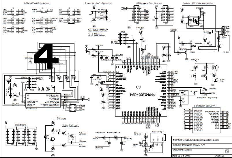
3 MSP-EXP430FG4618 The MSP430FG4618/F2013 experimenter s board is based on the Texas Instruments ultra-low power MSP430 family of microcontrollers [1, 2]. Residing on this board are the MSP430FG4618 [3] and the MSP430F2013 [4] microcontrollers.
4 An MSP430 Flash Emulation Tool (MSP-FET430UIF) is required to download code and debug the MSP430FG4618 and MSP430F2013. Two separate JTAG headers are available, supporting independent debug environments. MSP430FG4618 uses the standard 4-wire JTAG connection while the MSP430F2013 uses the Spy-Bi-wire (2-wire) JTAG interface allowing all port pins to be used during debug.
5 Wireless communication is possible through the expansion header which is compatible with all Chipcon Wireless Evaluation Modules from Texas Instruments. Interface to a 4-mux LCD, UART connection, microphone, audio output jack, buzzer, and single touch capacitive touch pad enable the development of a variety of applications. Communication between the two on-board microcontrollers is also possible. In addition, all pins of the MSP430FG4618 are made available either via headers or interfaces for easy debugging.
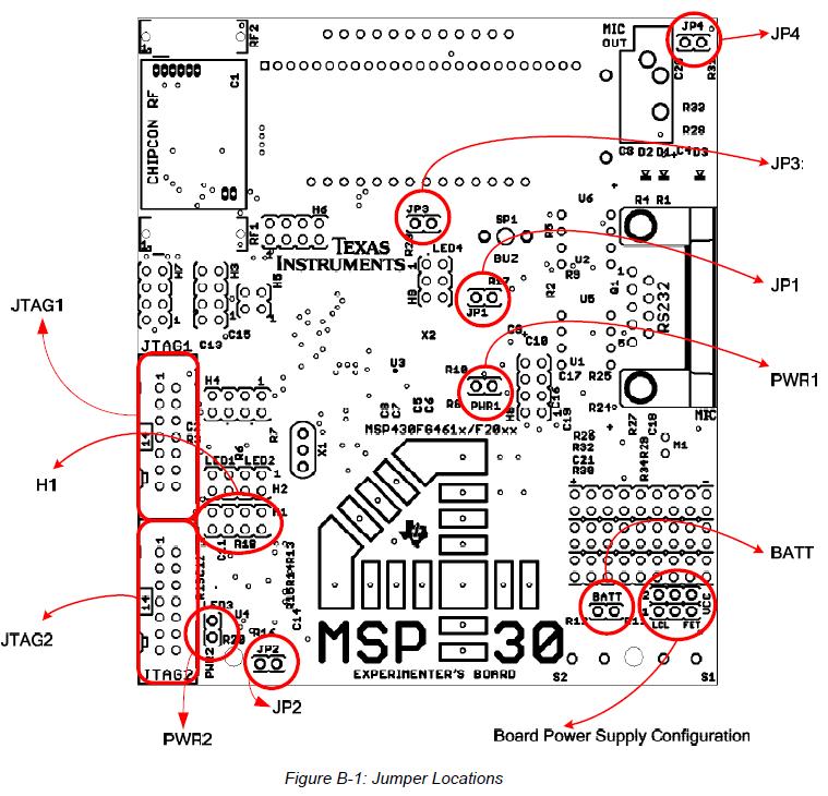
6 Power may be provided locally from two on-board AAA batteries, externally from a Flash emulation tool (FET), or an external supply. The power source is selected by configuring jumpers VCC_1, VCC_2, and BATT. PWR1 and PWR2 will supply power to each MSP430 independently. The battery jumper BATT is used to select the on-board batteries to power the system, independent of the FET connections. The user must ensure that this voltage meets the requirement for proper functionality of the MSP430.
7 The power selection jumpers VCC_1 and VCC_2 select the power connections between the board and each FET interface. These jumpers are two rows of 3-pin headers, one for each MSP430 on-board. VCC_1, the bottom row, is for the MSP430FG4618 and, VCC_2 on the top row, is for the MSP430F2013. A jumper placed on the rightmost 2-pins (FET) selects the JTAG FET as the power source. A jumper placed on the leftmost 2-pins (LCL) would enable local power (either from the batteries or an external supply) to be applied to each FET for proper logic threshold level matching during program/debug.
8 Headers PWR1 and PWR2 have been provided to enable power to the individual MSP430s. A jumper placed on PWR1 provides power to the MSP430FG4618 and a jumper placed on PWR2 provides power to the MSP430F2013. Individual device current consumption can be measured via each of these jumpers. Once the required power selections have been made the experimenter s board is ready to be used. Both the MSP430FG4618 and MSP430F2013 are factory programmed. After power up, the MSP430FG4618 executes an ultra-low power real-time clock displayed on the LCD
9 Some of these interfaces have the option of being inactive when not in use to conserve power. This is made possible by MSP430 port pin configurations and/or hardware jumpers on-board. 4-Mux LCD Display The integrated SoftBaugh SBLCDA4 LCD display supports 4-MUX operation and interfaces to the LCD driver peripheral of the MSP430FG4618. More information on the LCD can be obtained from the manufacturer s datasheet. Momentary-On Push Buttons Two external push buttons, S1 and S2, are connected to the interrupt capable MSP430FG4618 digital I/O port, P1. Light Emitting Diodes (LEDs) The experimenter board has a total of four LEDs, three connected to the MSP430FG4618 and one connected to the MSP430F2013. The LEDs are primarily used for display purposes. Two of the LEDs can be disconnected using jumpers to reduce the overall power consumption of the board. Buzzer A buzzer is connected to a digital I/O port of the MSP430FG4618. It is driven via a port pin of the MSP430. The buzzer can be completely disconnected by using jumper JP1. Single-Touch Sensing Interface A capacitive touch sensing interface in the shape of a 4 is provided onboard. This touchpad is connected to the digital I/O ports of the MSP430F2013. A total of 16 individual segments form the touchpad, and activity is monitored by the MSP430F2013. The resulting data is communicated to the MSP430FG4618 via the MSP430 intercommunication connections provided on-board.
10 Communication Peripherals Chipcon Wireless Evaluation Module Interface Interface to the wireless world is accomplished via the Wireless Evaluation Module header supporting the CCxxxxEMK boards from TI. The transceiver modules are connected to the USART of the MSP430FG4618 configured in SPI mode. Libraries [6] that interface the MSP430 to these transceivers are available at The CC2420EMK supports the /Zigbee standard. The CC1100EMK may be configured to work at an RF carrier frequency of up to 868 MHz and the CC2500EMK/CC2420EMK at an RF carrier frequency of 2.4 GHz. RS-232 For a serial interface to a PC, the MSP430FG4618 supports the standard RS pin interface via its USCI peripheral configured in UART mode. Standard baud rates for transmission and reception can be configured using in software I2C/SPI The MSP430FG4618 and the MSP430F2013 have support for I2C and SPI protocols using the USCI and the USI peripherals. This protocol is used for interprocessor communication The link can be disconnected in hardware allowing these peripherals to be used for other communication purposes.
11 Analog Signal Chain The experimenter s board is capable of forming a complete analog signal chain using the MSP430FG4618. This board can be used for numerous audio applications and is capable of recording and playback of audio signals without the use of additional external components.
12 Microphone The microphone is connected to the MSP430FG4618 and may be used for various applications. The microphone is enabled/disabled via a port pin connected to the MSP430FG4618. An active first order high-pass filter (HPF) with a cut-off frequency set at approximately 340Hz follows the microphone to eliminate extremely low input frequencies. An optional 2nd order Sallen-Key active lowpass filter (LPF) with a cut-off frequency set to approximately 4 khz removes the highfrequency noise on the analog output of the 12-bit DAC.
13 Analog Output Analog output can be brought out of the board via a mono 3.5mm jack connected to the integrated Op-Amp OA2. The input to this amplifier can be internally connected to the DAC12 output of the MSP430FG4618. Several attenuation options are provided internally and in hardware using jumper JP4.
14 System Clocks The experimenter s board has various system clock options that support low and high frequencies. Each MSP430 has integrated clock sources as well as support for external connections. MSP430F2013 Clock Sources The MSP430F2013 uses the internal VLO operating at ~12kHz for an ultra-low power standby wake up time base. The integrated DCO is internally programmable at frequencies up to 16MHz for high speed CPU and system clocking. MSP430FG4618 Clock Sources A standard kHz watch crystal is populated at footprint X2 and sources source ACLK of the MSP430FG4618 for low frequency, ultra-low power standby operation and RTC functionality. The integrated FLL+ clock module provides a programmable internal high frequency clock source for the CPU and other peripherals on-chip. In addition to the FLL+, an external high frequency crystal or resonator up to 8MHz can be added via footprint X1.
15 Procedure By analysis of the schematics, we need to determine which I/O port pin is connected to the LED on the board: - Consult the MSP430FG4618/F2013 Experimenter s Board User's Guide slau213a.pdf - LED1 is connected to Port Consult the ez430-f2013 Development Tool User's Guide slau176b.pdf - LED1 is connected to Port Consult the ez430-rf2500 Development Tool User's Guide slau227c.pdf - LED is connected to Port 1.0
16
17
18
19 Include the standard register and bit definitions for the TI MSP430 microcontroller device (example for the SP430FG18/MSP430F2013 Experimenter's board): #include <msp430xg46x.h> Define the main routine: void main (void){ The watchdog timer must be prevented from generating a PUC. Write 0x5A to the eight MSBs of the Watchdog timer control register, WDTCTL: WDTCTL = WDTHOLD WDTPW; Port control registers: - Set the LED port pin as an output; P2DIR: Port 2.2 is set as an output: P2DIR = 0x04; // to force the pin setting. It is uses an OR operation ( ) with P2DIR and 0x04
20 Use an infinite loop to modify the state of the port; Use a software delay loop to generate the pause interval. (a long software delay loop is used here for simplicity - in real applications, a timer would be used) - Because no clock is defined, the device will use the khz watch crystal. In order for a rate of one blinking LED state transition each second, the software delay loop should count to approximately {30000/32768 = +/- 1 sec}; volatile unsigned int i; i while(1) { //Infinite loop i=30000; //Delay do (i-- --); while (i!=0); // Port control registers inside the loop: // P2OUT: To switch the port state between low and // high state during program execution: P2OUT ^= 0x04; } } // It uses an XOR operation ( ^ ) between P2OUT and 0x04:
21 Toggle the LED state by pressing the push button Button S1 is connected to Port 1.0; Ports control registers: - Set push button pin port as an input - P1DIR: Port 1.0 is set as an input: P1DIR &= ~0x01 // to force the pin setting to 0. It is uses an AND operation ( & ) between P1DIR and 0xFE - Enable interrupts to this pin port; - P1IE: Enable interrupt to port 1.0: P1IE = 0x01; // Interrupt Enable in P1.0 - PIIES: Call the port interrupt on a high-to-low transition: P1IES = 0x01; // P1.0 Interrupt flag high-to-low transition - Configure the watchdog timer to prevent a PUC during the program execution; WDTCTL = WDTPW WDTHOLD; //Stop Watchdog Timer - Enable Global Interrupts and configure low power mode 3; _BIS_SR (LPM3_bits + GIE); //Low Power Mode with interrupts enabled - Create a interrupt service routine, that includes: - Toggle LED1 pin port; - Delay for button debounce; - Clear interrupt flag.
22 #pragma vector=port1_vector interrupt void Port_1 (void) { volatile unsigned int i; P2OUT ^= 0x04; // Toggle Port P2.2 i=1500; // Delay, button debounce do (i--); while (i!=0); while (! (P1IN & 0x01)); // Wait for the release of the button i=1500; // Delay, button debounce do (i--); while (i!=0); P1IFG & = ~0x01; // Clean P1.0 Interrupt Flag }
23 Homework2 Write a code to work with MSP430 Enable/disable LED blinking by push button press by: Detect of the button is pressed: Include a control flow program variable that detects if the LED is blinking or not, when the button is pressed: Define a variable that indicates whether the LED is blinking; Set the program flow depending on the state of the variable.
24 Timers Introduction Correct system timing is a fundamental requirement for the proper operation of a real-time application. The timing definition can dictate how the data information processed during the execution of the application program. The clock implementations vary between devices in the MSP430 family. Each device provides different clock sources, controls and uses. The MSP430 4xx family has two general-purpose 16-bit or 8-bit counters and event timers, named Timer_A, Timer_B, and a Basic Timer. The timers may receive an internal or external clock. Timer_A and Timer_B also include multiple independent capture and compare blocks, with interrupt capabilities.
25 Example This example implements a memory clock using the features provided by Timer1. The clock is updated once every second by the Basic Timer1 interrupt service routine (ISR). This procedure also performs switching of LED1. In order to evaluate the execution time of the routine, LED2 is kept active during the execution of the ISR. When the ISR has completed, the device goes into low power mode, until the new interrupt wakes it up.
26 Example This application sets Basic Timer1 to generate an interrupt once every second. The interrupt service routine generated by this peripheral is required to update the clock stored in memory. Moreover, it must refresh the content of the clock displayed on the LCD. Thus, the system resources used by this application are: - Basic Timer1; - I/O ports; - LCD; - Interrupts; - Low power modes.
27 Software application organization The first task is to disable the Watchdog Timer. It should be stated that this feature, when used correctly, makes the application more robust. The resources needed for the LCD are all configured. The memory clock consists of setting three global variables: hour, min, and sec, all of the type unsigned char, used to store the hours, minutes and seconds values elapsed respectively since the beginning of the execution of the application. These variables are initialized with zero values. The LCD is refreshed at startup to show the initial clock value. LED1 is used as an indicator of Basic Timer1 ISR execution. The execution time can be determined through it. In addition, LED2 state switches whenever the Basic Timer1 ISR is executed. The Basic Timer1 is set to generate an interrupt once every second. The routine main() ends with the interrupts global activation and puts the device in low power mode, awaiting the next interrupt. Basic Timer1 ISR begins by activating LED2, indicating the beginning of the routine execution and then switches the state of LED1. The counters are updated in cascade and their contents updated on the LCD, through routines LCD_sec(), LCD_min() and LCD_hour(). The routine ends with switching the state of the clock separation points. Finally, LED2 is turned off.
28 Watchdog Timer The Watchdog Timer is disabled with the objective of reducing energy consumption, but giving up the protection afforded by it. This peripheral is configured by the WDTCTL register. Its access is protected by a password. The value to disable it: WDTCTL = WDTPW WDTHOLD; // Stop WDT
29 FLL+ configuration khz crystal is applied to the oscillator LFXT1. Since it is possible to select the internal capacitors using software, the value to write to the FLL_CTL0 configuration register to select the 8 pf capacitors is: FLL_CTL0 = XCAP18PF; // Set load cap for 32k xtal Taking into consideration the change mentioned earlier to the FLL+ module, what are the frequencies of each of the clock signals? ACLK = ; MCLK = ; SMCLK = ;
30 LED ports configuration LED1 and LED2 are connected to ports P2.2 and P2.1 respectively. How should they be configured so that just the bits related to these ports have digital output functions? P2DIR = 0x06; // P2.2 and P2.1 as output How should the P2OUT register be configured so that the application starts with LED1 on and LED2 off? P2OUT = 0x04; // LED1 on and LED2 off
31 Basic Timer1 configuration Basic Timer1 should generate an interrupt once every second. It uses two counters in series, so that the input of the BTCNT2 counter is the output of the BTCNT1 counter divided by 256. The BTCNT1 counter input is the ACLK with a khz frequency. If the selected output of the BTCNT2 counter is divided by 128, what is the time period associated with the Basic Timer1 interrupt? BTCTL = BTDIV BT_fCLK2_DIV128; // (ACLK/256)/128 IE2 = BTIE; // Enable Basic Timer1 interrupt
32 //********************************************************* // BasicTimer1 Interrupt Service Routine //********************************************************* #pragma vector=basictimer_vector interrupt void basic_timer_isr(void) { P2OUT =0x02; // LED1 turn on P2OUT ^=0x04;// LED2 toogle sec++; // increment seconds LCD_sec(); // refresh seconds field in LCD if (sec == 60) // one minute { sec = 0; // reset seconds counter min++; // increment minutes LCD_min(); // refresh minutes field in LCD if (min == 60) // one hour was pass { min = 0; // reset minutes counter hour++; // increment hours LCD_min(); // refresh hours field in LCD if (hour == 24)// one day was pass { hour = 0; // reset hours counter } } } if (sec & 0x01) // toogle clock dots { P3_DOT_ON; P5_DOT_ON; } else { P3_DOT_OFF; P5_DOT_OFF; } P2OUT &=~0x02; // LED1 turn off }
33 Using the Low Power Modes The MSP430 was designed with the low power modes in mind from its beginnings. In lower power mode, the processor can achieve current in the microamps while still monitoring its inputs. While the 226 board cannot take advantage of this ability because of the other higher power components on the board, the principles of utilizing the MSP power modes are described in detail in the second chapter of the MSP User's Guide. The modes vary the degree to which the processor is aware of its surroundings and the clocks that the processor keeps running. The processor lowers power consumption partly by shutting off external and internal oscillators.
34 There are four low power modes in addition to regular operating mode on the MSP430: Active Mode is the fully powered mode when the processor executes code and all clocks and peripherals are active. The chip consumes about 340 µa with 1 MHz clock at 3.3V in this mode. Low Power Mode 1 (LPM1) disables the CPU and MCLK while leaving the ACLK and SMCLK enabled. This allows timers, peripherals, and analog systems to continue operation while dropping current consumption to about 70 µa with 1MHz clock at 3.3V. Because the timers and other internal interrupt systems still operate, the processor will be able to wake itself. Low Power Mode 2 (LPM2) disables the CPU, MCLK, and the DCO are disabled but the SMCLK and ACLK are active. The DC is disabled if the DCO is not used for MCLK or SMCLK in active mode. Internal interrupts can still operate. Current consumption drops to about 17 µa. Low Power Mode 3 (LPM3) disables the CPU, MCLK, SMCLK, and DCO. The DC and ACLK remain active. This allows some peripherals and internal interrupts to continue. Current consumption drops to about 2 µa. Low Power Mode 4 (LPM4) Current consumption drops to about.1 µa, but all clocks and the CPU are disabled. This prevents any of the on-chip modules from operating, and only off-chip interrupts can wake the device.
35 To enter a low power mode the status register in the CPU must be set to indicate the desired mode. Specifically the bits SCG1, SCG0, OSCOFF, and CPUOFF. The User's Guide details the specific bits needed. Also provided in the chapter is some example code on changing power modes. To exit low power mode, an interrupt is needed. In the interrupt, the previous status register state can be altered so that exiting the interrupt will leave the processor awake. The User's Guide explains in detail the specifics of entering and leaving low power mode.
36 LCD message display The Experimenter s board uses a LCD, which does not have its own controller. The operation is controlled by MSP430FG4618. it is possible to define the values to write to each of the memory registers to turn on the desired segments, or to set several of them, as is the case with numbers. configure the Ports P5.2, P5.3, P5.4 to special function COM1, COM2 and COM3, respectively
CPE 323 Introduction to Embedded Computer Systems: MSP430 System Architecture An Overview
 CPE 323 Introduction to Embedded Computer Systems: MSP430 System Architecture An Overview Aleksandar Milenkovic Electrical and Computer Engineering The University of Alabama in Huntsville milenka@ece.uah.edu
6. General purpose Input/Output
 Chapter 6 6. General purpose Input/Output This chapter starts with a description of one of the simplest integrated peripherals of the MSP430 the General Purpose 8-bit Input Output (GPIO). The Input/Output
Lab 1: I/O, timers, interrupts on the ez430-rf2500
 Lab 1: I/O, timers, interrupts on the ez430-rf2500 UC Berkeley - EE 290Q Thomas Watteyne January 25, 2010 1 The ez430-rf2500 and its Components 1.1 Crash Course on the MSP430f2274 The heart of this platform
ECE2049: Embedded Computing in Engineering Design C Term Spring 2019 Lecture #22: MSP430F5529 Operating Mode & the WDT
 ECE2049: Embedded Computing in Engineering Design C Term Spring 2019 Lecture #22: MSP430F5529 Operating Mode & the WDT Reading for Today: User's Guide 1.4, Ch 16 Reading for Next Class: Review all since
Create and Add the Source File
 IAR Kickstart Procedure Create and Add the Source File 8. Create the Source File From the IAR Embedded Workbench menu bar, select File New File. In the untitled editor window that appears, type the following
IV B.Tech. I Sem (R13) ECE : Embedded Systems : UNIT -2 1 UNIT 2
 ECE : Embedded Systems : UNIT -2 1 UNIT 2") IV B.Tech. I Sem (R13) ECE : Embedded Systems : UNIT -2 1 UNIT 2 1. Block diagram of MSP430x5xx series micro-controller --------------------- 1 2. CPU architecture of MSP430x5xx ------------------------------------------------
IV B.Tech. I Sem (R13) ECE : Embedded Systems : UNIT -2 1 UNIT 2 1. Block diagram of MSP430x5xx series micro-controller --------------------- 1 2. CPU architecture of MSP430x5xx ------------------------------------------------
CPE 325: Embedded Systems Laboratory Laboratory #7 Tutorial MSP430 Timers, Watchdog Timer, Timers A and B
 CPE 325: Embedded Systems Laboratory Laboratory #7 Tutorial MSP430 Timers, Watchdog Timer, Timers A and B Aleksandar Milenković Email: milenka@uah.edu Web: http://www.ece.uah.edu/~milenka Objective This
嵌入式微處理機 Embedded Microprocessors
 嵌入式微處理機 Embedded Microprocessors Text Book: TI's Teaching ROMs References: MSP 430 family data sheets and user's guides http://www.ti.com/ww/eu/university/r oms.html Info Time:Mon. 6, 7, 8 (EE 501) Evaluation:
Texas Instruments Mixed Signal Processor Tutorial Abstract
 Texas Instruments Mixed Signal Processor Tutorial Abstract This tutorial goes through the process of writing a program that uses buttons to manipulate LEDs. One LED will be hard connected to the output
CPE 323: MSP430 Timers
 CPE 323: MSP430 Timers Aleksandar Milenkovic Electrical and Computer Engineering The University of Alabama in Huntsville milenka@ece.uah.edu http://www.ece.uah.edu/~milenka Outline Watchdog Timer TimerA
Lecture 5: MSP430 Interrupt
 ECE342 Intro. to Embedded Systems Lecture 5: MSP430 Interrupt Ying Tang Electrical and Computer Engineering Rowan University 1 How A Computer React to Inputs? Polling: the processor regularly looks at
Lab 4 Interrupts ReadMeFirst
 Lab 4 Interrupts ReadMeFirst Lab Folder Content 1) ReadMeFirst 2) Interrupt Vector Table 3) Pin out Summary Objectives Understand how interrupts work Learn to program Interrupt Service Routines in C Language
5xx Active & Low Power Mode Operation
 5xx Active & Low Power Mode Operation 38 Lab 2: ULP Operation Lab Goals Learn ULP Best Practices Learn & understand how to configure two key modules of the 5xx to achieve ultra-low power operation. Power
Getting Started with the Texas Instruments ez430
 1 of 6 03.01.2009 01:33 HOME Running Your Code>> Getting Started with the Texas Instruments ez430 Working with the Workbench Software Step 1: Each program needs an associated project. The project includes
Intro. MEB/ Texas Instruments Inc, Slide 1
 Intro MEB/0404 2004 Texas Instruments Inc, Slide 1 MSP430 Agenda Core Architecture Integrated Peripherals Device Roadmap Ideal Applications Development Tools MEB/0404 2004 Texas Instruments Inc, Slide
University of Texas at El Paso Electrical and Computer Engineering Department. EE 3176 Laboratory for Microprocessors I.
 University of Texas at El Paso Electrical and Computer Engineering Department EE 3176 Laboratory for Microprocessors I Fall 2016 LAB 03 Low Power Mode and Port Interrupts Goals: Bonus: Pre Lab Questions:
ECE2049: Embedded Computing in Engineering Design C Term Spring Lecture #11: More Clocks and Timers
 ECE2049: Embedded Computing in Engineering Design C Term Spring 2018 Lecture #11: More Clocks and Timers Reading for Today: Davie's Ch 8.3-8.4, 8.9-8.10, User's Guide Ch. 17 Reading for Next Class: User's
CPE/EE 323 Introduction to Embedded Computer Systems Homework V
 CPE/EE 323 Introduction to Embedded Computer Systems Homework V 1(15) 2(15) 3(25) 4(25) 5(20) Total Problem #1 (15 points) Power, Low power systems A sensor platform features a microcontroller, a sensor,
Interfacing CMA3000-D01 to an MSP430 ultra low-power microcontroller
 Interfacing CMA3000-D01 to an MSP430 ultra low-power microcontroller 1 INTRODUCTION The objective of this document is to show how to set up SPI/I2C communication between VTI Technologies CMA3000-D01 digital
University of Texas at El Paso Electrical and Computer Engineering Department. EE 3176 Laboratory for Microprocessors I.
 University of Texas at El Paso Electrical and Computer Engineering Department EE 3176 Laboratory for Microprocessors I Fall 2016 LAB 04 Timer Interrupts Goals: Learn about Timer Interrupts. Learn how to
2.996/6.971 Biomedical Devices Design Laboratory Lecture 6: Microprocessors II
 2.996/6.971 Biomedical Devices Design Laboratory Lecture 6: Microprocessors II Instructor: Dr. Hong Ma Oct. 1, 2007 Structure of MSP430 Program 1. Declarations 2. main() 1. Watch-dog timer servicing 2.
Lab 4: Interrupt. CS4101 Introduction to Embedded Systems. Prof. Chung-Ta King. Department of Computer Science National Tsing Hua University, Taiwan
 CS4101 Introduction to Embedded Systems Lab 4: Interrupt Prof. Chung-Ta King Department of Computer Science, Taiwan Introduction In this lab, we will learn interrupts of MSP430 Handling interrupts in MSP430
MSP430FG4618/F2013 Experimenter s Board. User's Guide SLAU213A
 MSP0FG/F0 Experimenter s Board U s e r ' s G u i d e User's Guide October 00 SLAUA Mixed Signal Products EVM TERMS AND CONDITIONS Texas Instruments (TI) provides the enclosed Evaluation Module and related
Alex Milenkovich 1. CPE/EE 421 Microcomputers: The MSP430 Introduction. Outline
 Outline CPE/EE 421 Microcomputers: The MSP430 Introduction Instructor: Dr Aleksandar Milenkovic Lecture Notes MSP430: An Introduction The MSP430 family Technology Roadmap Typical Applications The MSP430
063[[[0LFURFRQWUROOHUV /RZ3RZHU0RGHV &3($GYDQFHG0LFURFRPSXWHU7HFKQLTXHV 'U(PLO-RYDQRY /RZ3RZHU. Power: A First-Class Architectural Design Constraint
 063[[[0LFURFRQWUROOHUV /RZ3RZHU0RGHV &3($GYDQFHG0LFURFRPSXWHU7HFKQLTXHV 'U(PLO-RYDQRY MSP430 low power concepts 1 /RZ3RZHU Power: A First-Class Architectural Design Constraint Trevor Mudge, IEEE Computer,
Interrupts, Low Power Modes
 Interrupts, Low Power Modes Registers Status Register Interrupts (Chapter 6 in text) A computer has 2 basic ways to react to inputs: 1) polling: The processor regularly looks at the input and reacts as
Timers and Clocks CS4101 嵌入式系統概論. Prof. Chung-Ta King. Department of Computer Science National Tsing Hua University, Taiwan
 CS4101 嵌入式系統概論 Timers and Clocks Prof. Chung-Ta King Department of Computer Science, Taiwan Materials from MSP430 Microcontroller Basics, John H. Davies, Newnes, 2008 Recall the Container Thermometer Container
ECE PRACTICE EXAM #2 Clocks, Timers, and Digital I/O
 ECE2049 -- PRACTICE EXAM #2 Clocks, Timers, and Digital I/O Study HW3, Class Notes, Davies Ch 2.6, 5.8, 8, 9.2-3, 9.7, MSP43F5529 User's Guide Ch 5, 17, 28 Work all problems with your note sheet first
Designing for Ultra-Low Power with MSP430
 Designing for Ultra-Low Power with MSP430 Christian Hernitscheck MSP430 FAE Europe Texas Instruments 2006 Texas Instruments Inc, Slide 1 Agenda Introduction to Ultra-Low Power Looking for Ultra-Low Power
Team 3. By: Miriel Garcia. Microcontrollers/ TI MSP430F5438A. ECE 480 senior Design. Application Note 4/3/15
 Microcontrollers/ TI MSP430F5438A ECE 480 senior Design Team 3 Application Note By: Miriel Garcia 4/3/15 Abstract Microcontrollers are key components on today s modern world. These devices have the ability
Interfacing CMR3000-D01 to an MSP430 ultra low-power microcontroller
 Interfacing CMR3000-D01 to an MSP430 ultra low-power microcontroller 1 INTRODUCTION The objective of this document is to show how to set up SPI/I2C communication between VTI Technologies CMR3000-D01 digital
Network Embedded Systems Sensor Networks Fall Hardware. Marcus Chang,
 Network Embedded Systems Sensor Networks Fall 2013 Hardware Marcus Chang, mchang@cs.jhu.edu 1 Embedded Systems Designed to do one or a few dedicated and/or specific functions Embedded as part of a complete
Chapter 1 MSP430 Microcontroller Family
 Chapter 1 1-1 Introduction 1.1 Introduction The MSP430 is a 16-bit microcontroller that has a number of special features not commonly available with other microcontrollers: Complete system on-a-chip includes
Application Report. 1 Hardware Description. John Fahrenbruch... MSP430 Applications
 Application Report SLAA309 June 2006 Low-Power Tilt Sensor Using the MSP430F2012 John Fahrenbruch... MSP430 Applications ABSTRACT The MSP430 family of low-power microcontrollers are ideal for low-power
What is an Interrupt?
 MSP430 Interrupts What is an Interrupt? Reaction to something in I/O (human, comm link) Usually asynchronous to processor activities interrupt handler or interrupt service routine (ISR) invoked to take
Hacettepe University
 MSP430 Teaching Materials Week 5 FUNDAMENTALS OF INTERFACING AND TIMERS for MSP430 Hacettepe University Elements in Basic MCU Interface Power Source Feeds CPU and peripherals Clock Oscillators System synchronization
// Conditions for 9600/4=2400 Baud SW UART, SMCLK = 1MHz #define Bitime_5 0x05*4 // ~ 0.5 bit length + small adjustment #define Bitime 13*4//0x0D
 /****************************************************************************** * * * 1. Device starts up in LPM3 + blinking LED to indicate device is alive * + Upon first button press, device transitions
Copyright 2015 by Stephen A. Zajac & Gregory M. Wierzba. All rights reserved..spring 2015.
 Copyright 2015 by Stephen A. Zajac & Gregory M. Wierzba. All rights reserved..spring 2015. Copyright 2015 by Stephen A. Zajac & Gregory M. Wierzba. All rights reserved..spring 2015. Copyright 2015 by Stephen
Wireless Sensor Networks (WSN)
") Wireless Sensor Networks (WSN) Operating Systems M. Schölzel Operating System Tasks Traditional OS Controlling and protecting access to resources (memory, I/O, computing resources) managing their allocation
Wireless Sensor Networks (WSN) Operating Systems M. Schölzel Operating System Tasks Traditional OS Controlling and protecting access to resources (memory, I/O, computing resources) managing their allocation
CPE/EE 421 Microcomputers
 CPE/EE 421 Microcomputers Instructor: Dr Aleksandar Milenkovic Lecture Note S13 *Material used is in part developed by Dr. D. Raskovic and Dr. E. Jovanov CPE/EE 421/521 Microcomputers 1 MSP430 Documentation
Analog Peripherals. Introduction. Objectives
 Analog Peripherals Introduction In this section we ll take a look at the MSP430 analog peripherals. It s not possible in this limited amount of time to give you a complete overview of the possible analog
AVR XMEGA Product Line Introduction AVR XMEGA TM. Product Introduction.
 AVR XMEGA TM Product Introduction 32-bit AVR UC3 AVR Flash Microcontrollers The highest performance AVR in the world 8/16-bit AVR XMEGA Peripheral Performance 8-bit megaavr The world s most successful
8051 Microcontroller
 8051 Microcontroller The 8051, Motorola and PIC families are the 3 leading sellers in the microcontroller market. The 8051 microcontroller was originally developed by Intel in the late 1970 s. Today many
FAE Summit Interfacing the ADS8361 to the MSP430F449 Low Power Micro Controller
 FAE Summit February 2004 FAE Summit 2004 - Interfacing the ADS8361 to the MSP430F449 Low Power Micro Controller Tom Hendrick High Performance Analog - Data Acquisition Products Group LAB OBJECTIVES This
Embedded Technosolutions
 MSP430 Tutorial Very Important Low Power Processor For Embedded Systems Applications Introduction Although there are many resources dedicated to teaching microcontrollers and the MSP430 in particular,
University of Texas at El Paso Electrical and Computer Engineering Department. EE 3176 Laboratory for Microprocessors I.
 University of Texas at El Paso Electrical and Computer Engineering Department EE 3176 Laboratory for Microprocessors I Fall 2016 LAB 08 UART Communication Goals: Learn about UART Communication and the
2006 Mixed Signal Products SLAU049F
 User s Guide 2006 Mixed Signal Products SLAU049F Related Documentation From Texas Instruments Preface About This Manual This manual discusses modules and peripherals of the MSP430x1xx family of devices.
Hands-On: Implementing an RF link with MSP430 and CC1100
 Hands-On: Implementing an RF link with MSP430 and CC1100 Keith Quiring MSP430 Applications Engineer Texas Instruments 2006 Texas Instruments Inc, Slide 1 Overview Introduction Target Hardware Library File
2002 Mixed Signal Products SLAU056B
 User s Guide 22 Mixed Signal Products SLAU56B IMPORTANT NOTICE Texas Instruments Incorporated and its subsidiaries (TI) reserve the right to make corrections, modifications, enhancements, improvements,
RF Networking With MSP430 & the ez430-rf2500 Session 2 Miguel Morales, MSP430 Applications 6/5/2008 1
 RF Networking With MSP430 & the ez430-rf2500 Session 2 Miguel Morales, MSP430 Applications 6/5/2008 1 Agenda Recap of Session 1 Hardware description Session 2 Lab Overview Lab 2.1 Tilt & Ambient Noise
MICROPROCESSOR BASED SYSTEM DESIGN
 MICROPROCESSOR BASED SYSTEM DESIGN Lecture 5 Xmega 128 B1: Architecture MUHAMMAD AMIR YOUSAF VON NEUMAN ARCHITECTURE CPU Memory Execution unit ALU Registers Both data and instructions at the same system
MSP430xxxx Microcontrollers Low Power Modes
 MSP430xxxx Microcontrollers Low Power Modes Modes à basse consommation 1 Power is a priority architectural design constraint Why worry about power? Battery life in portable and mobile platforms Power consumption
Block diagram of processor (Harvard)
") Block diagram of processor (Harvard) Register transfer view of Harvard architecture Separate busses for instruction memory and data memory Example: PIC 16 load path OP REG AC 16 16 store path rd wr data
Block diagram of processor (Harvard) Register transfer view of Harvard architecture Separate busses for instruction memory and data memory Example: PIC 16 load path OP REG AC 16 16 store path rd wr data
Embedded Systems. 3. Hardware Software Interface. Lothar Thiele. Computer Engineering and Networks Laboratory
 Embedded Systems 3. Hardware Software Interface Lothar Thiele Computer Engineering and Networks Laboratory Do you Remember? 3 2 3 3 High Level Physical View 3 4 High Level Physical View 3 5 What you will
CPE 323 Introduction to Embedded Computer Systems: ADC12 and DAC12. Instructor: Dr Aleksandar Milenkovic Lecture Notes
 CPE 323 Introduction to Embedded Computer Systems: ADC12 and DAC12 Instructor: Dr Aleksandar Milenkovic Lecture Notes Outline MSP430: System Architecture ADC12 Module DAC12 Module CPE 323 2 ADC12 Introduction
AIM: To create a project for implement a wireless communication protocol on an embedded system- ZigBee.
 AIM: To create a project for implement a wireless communication protocol on an embedded system- ZigBee. Introduction ZigBee is one of the Advanced Wireless Technology and CC2430 is the first single-chip
Hacettepe University
 MSP430 Teaching Materials Week 5 FUNDAMENTALS OF INTERFACING AND TIMERS for MSP430 Hacettepe University Elements in Basic MCU Interface Power Source Feeds CPU and peripherals Clock Oscillators System synchronization
AVR XMEGA TM. A New Reference for 8/16-bit Microcontrollers. Ingar Fredriksen AVR Product Marketing Director
 AVR XMEGA TM A New Reference for 8/16-bit Microcontrollers Ingar Fredriksen AVR Product Marketing Director Kristian Saether AVR Product Marketing Manager Atmel AVR Success Through Innovation First Flash
Alex Milenkovich 1. CPE/EE 421 Microcomputers. Course Administration. Review: Outline. Getting Started with EasyWeb2. Review: MSP bit RISC
 CPE/EE 421 Microcomputers Instructor: Dr Aleksandar Milenkovic Lecture Note S12 Course Administration Instructor: URL: TA: Labs: Test I: Text: Review: Today: Aleksandar Milenkovic milenka@ece.uah.edu www.ece.uah.edu/~milenka
Hello, and welcome to this presentation of the STM32L4 power controller. The STM32L4 s power management functions and all power modes will also be
 Hello, and welcome to this presentation of the STM32L4 power controller. The STM32L4 s power management functions and all power modes will also be covered in this presentation. 1 Please note that this
MSP430FG4618 Programming Reference Revision 3
 MSP430FG4618/F2013 Experimenter Board MSP430FG4618 Programming Reference Revision 3 George Mason University 1. CPU Registers The CPU incorporates sixteen 20-bit registers. R0, R1, R2 and R3 have dedicated
Hacettepe University
 www.msp430.ubi.pt MSP430 Teaching Materials Introductory Overview Week2 Hacettepe University Outline Microcontrollers Versus Microprocessors Central Processing Unit System Buses Memory Organization I/O
The industrial technology is rapidly moving towards ARM based solutions. Keeping this in mind, we are providing a Embedded ARM Training Suite.
 EMBEDDED ARM TRAINING SUITE ARM SUITE INCLUDES ARM 7 TRAINER KIT COMPILER AND DEBUGGER THROUGH JTAG INTERFACE PROJECT DEVELOPMENT SOLUTION FOR ARM 7 e-linux LAB FOR ARM 9 TRAINING PROGRAM INTRODUCTION
 Distributed by: www.jameco.com 1-800-831-4242 The content and copyrights of the attached material are the property of its owner. MSP430F11x2/12x2 Device Erratasheet Current Version Devices MSP430F1122
Understanding the new '5xx Integrated Power Management Module (PMM) Stefan Schauer
 Stefan Schauer") Understanding the new '5xx Integrated Power Management Module (PMM) Stefan Schauer 6/5/2008 1 Agenda Introduction into the PMM System Technical Data, specified Values Software controlled PMM configuration
Understanding the new '5xx Integrated Power Management Module (PMM) Stefan Schauer 6/5/2008 1 Agenda Introduction into the PMM System Technical Data, specified Values Software controlled PMM configuration
CPE 325: Embedded Systems Laboratory Laboratory #11 Tutorial Analog-to-Digital Converter and Digital-to-Analog Converter
 CPE 325: Embedded Systems Laboratory Laboratory #11 Tutorial Analog-to-Digital Converter and Digital-to-Analog Converter Aleksandar Milenković Email: milenka@uah.edu Web: http://www.ece.uah.edu/~milenka
Getting Started with the MSP430 LaunchPad
 Getting Started with the MSP430 LaunchPad Student Guide and Lab Manual Revision 2.01 February 2012 Technical Training Organization Important Notice Important Notice Texas Instruments and its subsidiaries
Programming in the MAXQ environment
 AVAILABLE The in-circuit debugging and program-loading features of the MAXQ2000 microcontroller combine with IAR s Embedded Workbench development environment to provide C or assembly-level application
Timer Module Timer A. ReadMeFirst
 Timer Module Timer A ReadMeFirst Lab Folder Content 1) ReadMeFirst 2) TimerModule Lecture material 3) PinOutSummary 4) InterruptsVectorTable 5) Source code for screencast Interrupt Review Overview A Timer
CPE/EE 421 Microcomputers
 CPE/EE 421 Microcomputers Instructor: Dr Aleksandar Milenkovic Lecture Note S11 MSP430 Documentation MSP430 home page (TI) www.ti.com/msp430 User s manual http://www.ece.uah.edu/~milenka/cpe421-05s/manuals/slau049c.pdf
Why embedded systems?
 MSP430 Intro Why embedded systems? Big bang-for-the-buck by adding some intelligence to systems. Embedded Systems are ubiquitous. Embedded Systems more common as prices drop, and power decreases. Which
2006 Mixed Signal Products SLAU049F
 User s Guide 2006 Mixed Signal Products SLAU049F IMPORTANT NOTICE Texas Instruments Incorporated and its subsidiaries (TI) reserve the right to make corrections, modifications, enhancements, improvements,
Quick Start Guide for the Turbo upsd DK3300-ELCD Development Kit- RIDE
 Contents: Circuit Board upsd DK3300-ELCD Development Board with a upsd3334d-40u6 MCU with Enhanced Graphic LCD RLINK-ST, a USB-based JTAG adapter from Raisonance for debugging with Raisonance Integrate
ZigBee Compliant Platform 2.4G RF Low Power Transceiver Module for IEEE Standard. DATA SHEET Version B
 ZMD400-A01 ZigBee Compliant Platform 2.4G RF Low Power Transceiver Module for IEEE 802.15.4 Standard DATA SHEET Version B Quan International Co., Ltd., ZMD400 Features Fully compliant 802.15.4 Standard
MSP430 Microcontroller Basics
 MSP430 Microcontroller Basics John H. Davies AMSTERDAM BOSTON HEIDELBERG LONDON NEW YORK OXFORD PARIS SAN DIEGO SAN FRANCISCO SINGAPORE SYDNEY TOKYO Newnes is an imprint of Elsevier N WPIGS Contents Preface
Getting Started with the MSP430 LaunchPad
 Getting Started with the MSP430 LaunchPad Student Guide and Lab Manual Revision 1.0 October 2010 Technical Training Organization Important Notice Important Notice Texas Instruments and its subsidiaries
CEIBO FE-5111 Development System
 CEIBO FE-5111 Development System Development System for Atmel W&M T89C5111 Microcontrollers FEATURES Emulates Atmel W&M T89C5111 4K Code Memory Real-Time Emulation and Trace Frequency up to 33MHz/5V ISP
The 16-bit timer/counter register, TAR, increments or decrements (depending on mode of operation) with each rising edge of the clock signal.
 with each rising edge of the clock signal.") Timer & Real Time Clock (RTC), PWM control, timing generation and measurements. Analog interfacing and data acquisition: ADC and Comparator in MSP430, data transfer using DMA. Case Study: MSP430 based
Timer & Real Time Clock (RTC), PWM control, timing generation and measurements. Analog interfacing and data acquisition: ADC and Comparator in MSP430, data transfer using DMA. Case Study: MSP430 based
8-bit Microcontroller. Application Note. AVR134: Real-Time Clock (RTC) using the Asynchronous Timer. Features. Theory of Operation.
 using the Asynchronous Timer. Features. Theory of Operation.") AVR134: Real-Time Clock (RTC) using the Asynchronous Timer Features Real-Time Clock with Very Low Power Consumption (4µA @ 3.3V) Very Low Cost Solution Adjustable Prescaler to Adjust Precision Counts Time,
AVR134: Real-Time Clock (RTC) using the Asynchronous Timer Features Real-Time Clock with Very Low Power Consumption (4µA @ 3.3V) Very Low Cost Solution Adjustable Prescaler to Adjust Precision Counts Time,
MSP430 Interrupts. Change value of internal variable (count) Read a data value (sensor, receive) Write a data value (actuator, send)
 Read a data value (sensor, receive) Write a data value (actuator, send)") MSP430 Interrupts What is an Interrupt? Reaction to something in I/O (human, comm link) Usually asynchronous to processor activities interrupt handler or interrupt service routine (ISR) invoked to take
MSP430 Interrupts What is an Interrupt? Reaction to something in I/O (human, comm link) Usually asynchronous to processor activities interrupt handler or interrupt service routine (ISR) invoked to take
Introduction to Microcontroller Apps for Amateur Radio Projects Using the HamStack Platform.
 Introduction to Microcontroller Apps for Amateur Radio Projects Using the HamStack Platform www.sierraradio.net www.hamstack.com Topics Introduction Hardware options Software development HamStack project
ECGR 4101/5101, Fall 2016: Lab 1 First Embedded Systems Project Learning Objectives:
 ECGR 4101/5101, Fall 2016: Lab 1 First Embedded Systems Project Learning Objectives: This lab will introduce basic embedded systems programming concepts by familiarizing the user with an embedded programming
WHICH MICRO? What does MCU needs to do in my system? What are the tasks? Dr. Adriana Becker-Gomez
 1 WHICH MICRO? What does MCU needs to do in my system? What are the tasks? Dr. Adriana Becker-Gomez Email: axbeec@rit.edu Office: 9-3477 2 Specs System design: High level definition (functional specs)
ECE2049 Homework #2 The MSP430 Architecture & Basic Digital IO (DUE Friday 9/8/17 at 4 pm in class)
") ECE2049 Homework #2 The MSP430 Architecture & Basic Digital IO (DUE Friday 9/8/17 at 4 pm in class) Your homework should be neat and professional looking. You will loose points if your HW is not properly
ECE2049 Homework #2 The MSP430 Architecture & Basic Digital IO (DUE Friday 9/8/17 at 4 pm in class) Your homework should be neat and professional looking. You will loose points if your HW is not properly
Lecture test next week
 Lecture test next week Write a short program in Assembler doing. You will be given the print outs of all the assembler programs from the manual You can bring any notes you want Today: Announcements General
MSP430 Interface to LMP91000 Code Library
 MSP430 Interface to LMP91000 Code Library 1.0 Abstract The MSP430 is an ideal microcontroller solution for low-cost, low-power precision sensor applications because it consumes very little power. The LMP91000
Name: Clint Furrer Project Number: TI003 Project Description: Safety Walking Lights. Description:
 Description: This project addresses the concern and problem of pedestrians walking with automotive traffic. I walk to and from a bus stop every morning and evening for work. There is usually low light
Clock and Fuses. Prof. Prabhat Ranjan Dhirubhai Ambani Institute of Information and Communication Technology, Gandhinagar
 Clock and Fuses Prof. Prabhat Ranjan Dhirubhai Ambani Institute of Information and Communication Technology, Gandhinagar Reference WHY YOU NEED A CLOCK SOURCE - COLIN O FLYNN avrfreaks.net http://en.wikibooks.org/wiki/atmel_avr
Mega128-DEVelopment Board Progressive Resources LLC 4105 Vincennes Road Indianapolis, IN (317) (317) FAX
 (317) FAX") Mega128-DEVelopment Board Progressive Resources LLC 4105 Vincennes Road Indianapolis, IN 46268 (317) 471-1577 (317) 471-1580 FAX http://www.prllc.com GENERAL The Mega128-Development board is designed for
Mega128-DEVelopment Board Progressive Resources LLC 4105 Vincennes Road Indianapolis, IN 46268 (317) 471-1577 (317) 471-1580 FAX http://www.prllc.com GENERAL The Mega128-Development board is designed for
Hibernation Module. Introduction. Agenda
 Hibernation Module Introduction In this chapter we ll take a look at the hibernation module and the low power modes of the M4F. The lab will show you how to place the device in sleep mode and you ll measure
MSP430 Interface to LMP91000 Code Library
 Application Note 2230 Vishy Viswanathan July 13, 2012 MSP430 Interface to LMP91000 Code 1.0 Abstract The MSP430 is an ideal microcontroller solution for low-cost, low-power precision sensor applications
BLE MODULE SPECIFICATIONS
 WIRELESS-TAG BLE MODULE SPECIFICATIONS nrf51-01/02/dk Bluetooth Low Energy (BLE) module of nrf51-01/02 is the next generation BLE module released by SEMITRION electronics. The modules use nrf51822 from
CPE 323: MSP430 Serial Communication
 CPE 323: MSP430 Serial Communication Aleksandar Milenkovic Electrical and Computer Engineering The University of Alabama in Huntsville milenka@ece.uah.edu http://www.ece.uah.edu/~milenka Outline Introduction
ARDUINO MEGA INTRODUCTION
 ARDUINO MEGA INTRODUCTION The Arduino MEGA 2560 is designed for projects that require more I/O llines, more sketch memory and more RAM. With 54 digital I/O pins, 16 analog inputs so it is suitable for
I/O Devices & Debugging. Jin-Soo Kim Computer Systems Laboratory Sungkyunkwan University
 I/O Devices & Debugging Jin-Soo Kim (jinsookim@skku.edu) Computer Systems Laboratory Sungkyunkwan University http://csl.skku.edu I/O Devices Jasmine Block Diagram ICE3028: Embedded Systems Design (Spring
Spartan-II Demo Board User s Guide
 Spartan-II Demo Board User s Guide Version.2 May 200 Overview The Spartan-II Demo Board is a low cost evaluation platform for testing and verifying designs based on the Xilinx Spartan-II family of FPGA
@databasescaling Wednesday, 18 th April 2013
 andyjpb@ashurst.eu.org @databasescaling Wednesday, 18 th April 2013 OSHUG #24 1 / 56 Writing C For Constrained Systems a@jpb.li @databasescaling Wednesday, 18 th April 2013 OSHUG #24 2 / 56 Writing C For
Introduction to the Texas Instruments ez430. By: Naren Anand
 Introduction to the Texas Instruments ez430 By: Naren Anand Introduction to the Texas Instruments ez430 By: Naren Anand Online: C O N N E X I O N S Rice University,
MSP430 Ultra-Low-Power Microcontrollers
 MSP430 Ultra-Low-Power Microcontrollers 2008 2 MSP430 Microcontrollers Key Features Ultra-low-power architecture and flexible clock system extends battery life: 0.1-µA RAM retention
Microcontroller Basics
 Microcontroller Basics Gabe Cohn CSE 599U February 6, 2012 www.gabeacohn.com/teaching/micro Outline Overview of Embedded Systems What is a Microcontroller? Microcontroller Features Common Microcontrollers