4 Degrees of Freedom MEMS Sensor Improvements
|
|
|
- Kristian Gardner
- 5 years ago
- Views:
Transcription
1 4 Degrees of Freedom MEMS Sensor Improvements Design Document Name: Xin Zhou Yue Zhang Team Dec12-09 Ang Lv Nicholas Everett Jenn Grubb Advisor: Degang Chen Client: Bee Line Company Bob Last Updated: Dec 1 st 2012
2 Contents Contents... 1 Problem Statement... 4 Project Objectives... 4 System Block Diagram... 5 Voltage Regulator... 6 Inclinometer... 7 Gyro: Angular Rate Sensors... 8 Micro-Processor... 9 System Description Operating environment User interface description Functional Requirements Non-Functional Requirements Expected Deliverables Work Plan Work Breakdown Costs Project Schedule Risks
3 Detailed Design Microcontroller Inclinometer Gyro Interconnects Schematic Design Microcontroller and JTAG Gyro Schematic Design Inclinometers Schematic Design Regulators Schematic Design Testing Points on Schematic Layout Design Gyro Footprint Information Inclinometer Footprint Information Regulator Footprint Information Overview of Layout Final Product Test Plan Connectivity Test Ground level test
4 Regulators Voltage Test SPI Connection Test & Rough Board Function Test Appendix
5 Problem Statement The Beeline Company in Bettendorf produces equipment for performing wheel alignments on larger commercial vehicles. Currently, they bring the vehicle into a large bay and prepare to perform the alignment of the wheels. They use two different circuit boards connected to a computer to perform the alignment. The first circuit board contains a microprocessor (to process the information from the accelerometer and the gyro) and a 3-axis accelerometer (to ensure no movement is occurring). The second circuit contains a 1-axis gyro that can measure the angle of the wheel being aligned and is connected to the first board. The client has found that the circuit boards currently have a high failure rate. Many times during the alignment, the circuit board will stop responding or provide data that is out of the tolerance that is necessary. This requires the technicians to reinitialize the boards and begin the alignment again. Project Objectives Beeline has requested for the team to design a new circuit board for their alignment process to replace their current circuit boards. The team has the option of either placing all components on one circuit board or maintaining their current setup by using two circuit boards. The circuits need to be able to measure degrees of accuracy from an accelerometer or inclinometer and 0.1 degree or better for at least 2 minutes from the gyro. 4
6 System Block Diagram: Figure 1 System Block Diagram 5
7 Voltage Regulator Figure 2 Voltage Regulator The voltage regulator is designed for portable and wireless applications with demanding performance and space requirements. The voltage regulator is stable with a small 1uF ±30% ceramic or high-quality tantalum output capacitor. It is optimized for battery powered systems to deliver ultra-low noise, extremely low dropout voltage and low quiescent current. Key Specifications: 2.5 to 6.0V input range 150mA guaranteed output 50dB PSRR at VIN = VOUT + 0.2V 1.5μA quiescent current when shut down Fast Turn-On time: 200 μs 100mV maximum dropout with 150mA load 30μVrms output noise over 10Hz to 100kHz 40 to +125 C junction temperature range for operation 2.5V, 2.6V, 2.7V, 2.8V, 2.85V, 2.9V, 3.0V, 3.1V, 3.2V, 3.3V, 4.7V, 4.8V and 5.0V outputs standard There are two regulators currently used on the circuit board. One is 3.2V, and the other one is 4.7V. 6
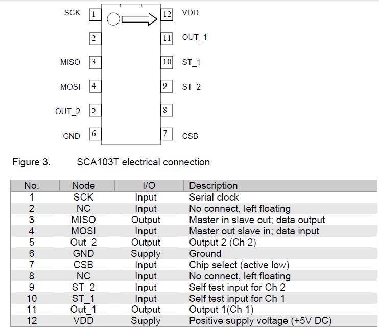
8 Inclinometer The Inclinometer consists of two different sensing devices, one that measures angular changes about the X-axis and another for the Y-axis. The two signals are then used to calculate an angular displacement in one direction. Therefore, for our circuit, we will have to use two of these devices placed orthogonal to each other. Figure 3 Inclinometer Functional Diagram We will be using the SCA103t inclinometer from VTI technologies. The SCA103T Series is a 3D-MEMSbased single axis inclinometer family that uses the differential measurement principle. The high calibration accuracy combines extremely low temperature dependency, high resolution and low noise together with a robust sensing element design, to make the SCA103T an ideal choice for high accuracy leveling instruments. The VTI inclinometers are insensitive to vibration due to having over damped sensing elements plus they can withstand mechanical shocks of g. 7
9 Gyro: Angular Rate Sensors Gyros measure angular velocity, how fast something is spinning about an axis. Unlike inclinometers, gyros are not affected by gravity, so they make a great complement to each other. The angular velocity is in units of rotations per minute, or degrees per second. They can also tell you the amount of angular displacement from a specified position. We will be using the L3G4200D gyroscope from ST Microelectronics. Figure 4 Gyro Block Diagram 8
10 Micro-Processor A microprocessor incorporates the functions of a computer s central processing unit on a single integrated circuit. The microprocessor which is in this system collects analog data from data bus transceiver, and then it converts the analog data into digital signals for analyzing. It also receives 3 axis analog data from the accelerometer, and then converts from analog to digital. The microprocessor also controls some LEDs which represent different warnings. 9
11 System Description Operating environment The boards could possibly be used in a Thermotron oven that heats up the air from about 40 degrees Fahrenheit to around 100 degree Fahrenheit. Therefore, the components on the boards need to be able to withstand the temperature swing and still operate normally. User interface description Beeline interfaces with their current sensor boards with connections to the microprocessor through a JTAG port to an Olimex USB programmer. The two separate boards also interface with each other using a Board to Board RA header connection. Functional Requirements Inclinometers must be able to measure roll and pitch axis within degrees accuracy. Gyro needs to be able to measure a single axis (yaw) and have an accuracy of at least 0.1 degrees for at least 2 minutes. Circuit needs to have low power consumption since batteries will be used to power them. Circuit board must be able to function properly in a temperature range of degrees Fahrenheit. Circuit Board containing microprocessor must be able to connect to other equipment via SPI connection. 10
12 Non-Functional Requirements Circuit boards should be 1.6 inches by 1.15 inches in dimension. Circuits should be testable via test equipment supplied by Beeline Company. Expected Deliverables The final expected product will be a complete circuit board system capable of running on lithium ion batteries. The board will contain a microprocessor, an accelerometer sensor and a gyro sensor. It will connect to Beeline s current programming setup with JTAG connections. There will either be one complete board with both accelerometer and gyro sensors or two separate boards capable of connecting together. 11
13 Work Plan Work Breakdown The following are tasks that the team needs to accomplish over the two semesters to ensure a successful finished product. Project Definition Component Selection Circuit Design Initial Design Testing Finalized Design Board Design Board Fabrication Product Testing and Validation Final Documentation 12
14 Costs Material costs for the project have not yet been determined and will depend on the component selection. The client has requested that the total costs for new parts be less than $150. The following is a preliminary cost estimate. Item Notes Cost Microprocessor $3.50 Inclinometer Two are required $41.10 *2 = $82.20 Gyro $7.90 PCB Components PCB Fabrication Surface mount components, input/output jacks, battery enclosure, etc. Unknown as of 04/17/12 $40 (Estimated. Unknown as of 04/17/12) Enclosure Unknown as of 04/17/12 Total $
15 Project Schedule Project Definition Component Selection Initial Circuit Design Testing Final Circuit Design Board Design Board Fabrication Completed Remaining Product Testing Final Documentaion Risks The major risk that we will face is the possibility of destroying any of the sensors or the microprocessor as they would be expensive to replace. The team can take precautionary measures by thoroughly analyzing and simulating a circuit before starting any testing procedures. This will help by reducing the risk of the circuit failing and damaging any of the components. 14
16 Detailed Design Microcontroller We will be using the same microcontroller as the current board setup in order to reduce cost for our client. The microcontroller is a MSP430F247 from Texas Instruments, which has low power modes that benefit battery-operated devices such as ours. It features a 16-bit RISC CPU, 16-bit registers, 48 I/O pins, and has not been a cause of problems for our client with the current design. Inclinometer The board will use two inclinometers positioned in perpendicular angles to measure the amount that the device tilts. Once the board no longer detects a change in angle, it will output a reading. The device we chose to use was a SCA103T series MEMS single axis inclinometer that has high resolution and low noise which contributes to its high accuracy. The device has a 12 bit data output, a current consumption of 5mA and a supply voltage range of V. The noise for this inclinometer is around /, or 6.96, making this an acceptable component for our client s specifications. The device will communicate with the microcontroller via SPI communication procedures. 15
17 Gyro The gyro we will be using is the L3G4200D from STMicroelectronics. The L3G4200D is a low-power three-axis angular rate sensor able to provide unprecedented stability of zero rate level and sensitivity over temperature and time. It includes a sensing element and an IC interface capable of providing the measured angular rate through a digital interface (SPI). It is an ultra-stable three axis digital output gyroscope that has three selectable ranges (250/500/2000 /s) which has a 16 bit data output. Some other features are that it is very stable over a wide temperature and time range, has a low power consumption of 6.1 ma during operation, and a wide supply voltage range. We will only be using the yaw axis of the gyro to satisfy the client s requirements and this may save on power consumption since the other two axes will not be in use. Interconnects The board to board connections will be made by using a board to board header. This will allow the gyro board to interface with the microprocessor on the other circuit board. The microprocessor board will receive its power via a Molex connector. All other data with be transferred via SPI between components. 16
18 Schematic Design Microcontroller and JTAG Figure 5, MSP430 and JTAG Schematic view By following the description that given in MSP430 data sheet, it is decided to use two groups of capacitors to stabilize the voltage. Use a JTAG to build up interface between microcontroller and the computer, so that the microcontroller can be programmed. There are two groups of SPI, one is connecting to the main board, and the other on group are controlling two inclinometers and a gyro, program PIN SSEL0, SSEL1, SSEL2, so that we can choose which component that we are going to send or receive data. SCL0 is used to be clock signal, and MISO is called master input slave output which is used to receive data from sensors. MOSI is called master output slave input, which is used to send control signals to the sensors. 17
19 Gyro Schematic Design Figure 6 Gyro Shcematic View Power supply decoupling capacitors (100 nf ceramic or polyester +10 μf) should be placed as near as possible to the device (common design practice). If Vdd and Vdd_IO are not connected together, power supply decoupling capacitors (100 nf and 10 μf between Vdd and common ground, 100 nf between Figure 7 Gyro (Vdd Connection) Vdd_IO and common ground) should be placed as near as possible to the device (common design practice). The L3G4200D IC includes a PLL (phase locked loop) circuit to 18
20 synchronize driving and sensing interfaces. Capacitors and resistors must be added at the PLLFILT pin (as shown in Figure 8 PLL of gyro As using a group of capacitors to stabilize the gyro Vdd, then use a PLL circuit to drive and sense interfaces. Then used SPI connection MOSI0 and MISO0 to control it, use SCK0 to clock it, and SSEL0 to select gyro when we want its data send off to microcontroller. Inclinometers Schematic Design Figure 9 Two Inclinometers 19

21 Figure 10 Inclinometer Connection Example As the example found from data sheet above, the inclinometer need a Vdd power which is about 5V, and then need connect a 100n capacitor to it. It also needs one SPI control since we only need its digital data. MOSI0 and MISO0 used as SPI, SCK0 used as clock, and SSEL1 and SSEL2 to select two inclinometers when we want its data send off to microcontroller. Regulators Schematic Design Figure 11 Two Regulators 20
22 The decision of the values of the regulators are made due to the power requirement of gyro and inclinometers. The gyro need typical Vdd of 3V and inclinometer need 5V, so we use 3V and 5V regulators. As left figure 12 shown, it requires 3 capacitors, two of them are 1 uf, and another one with star is called optional noise capacitor, which can be 1 uf too. Figure 12 Regulator Connection Testing Points on Schematic Figure 13 Testing Points Schematic View Since all of our components send off digital signal, we do not need to have a lot of testing points for our schematic design. For users more convenient, we still add five testing PINs to make sure everything is working fine on the sensor board. There are two voltage needed to be checked since they are produced by regulators, and then it will be the SPI connections, in order to check if it has a good SPI connection. 21
23 22
24 Layout Design For the layout part, some components that we have to create our own library of footprint since it is not possible to find one online. There is no worry to build the layout of microcontroller, because most of the software have the library layout for TI s MSP430. We do need to build our own footprint of gyro, inclinometers and regulators. Gyro Footprint Information 23
25 Inclinometer Footprint Information Figure 14 Footprint of Inclinometer size in (mm) Regulator Footprint Information Figure 15 Regulator Footprintin inches or (mm) 24

26 Overview of Layout Figure 16 Layout Overview There are total 2 layers for this sensor board, and every component is fit on the top board. 25

27 Final Product Figure 17 Manufactured Sensor Board 26
28 Test Plan Testing list: 1. Connections test 2. Ground level test 3. Regulators voltage test 4. SPI connection test & Rough function test 1)Connectivity Test The purpose of this test is to ensure that all the connections are correct on the circuit board prior to connecting any components or applying power. Required Items: Ohmmeter x 1 Connection leads x 2 People Required: Technician x 2 Instructions: This test will require two people (person A and person B). Person A will read a connection that should be checked while person B will use the ohmmeter to verify the connection. If a connection is made, the ohmmeter should indicate that by being very close to 0 ohms. If it is open, the ohmmeter will not be close to 0. All of the connections below should be near 0 ohms when checked. In the event one of the connections is not near 0 ohms, Person B should check to see whether either or both of those pins are connecting to any other connection. Example of Bad Connection: If Microcontroller pin 5 to Gyro pin 1 is reading 5M ohms, then person B should check Microcontroller pin 5 to every other pin on the board to ensure that it is not wired to the incorrect place. Person B should also do the same for Gyro pin 1. If any connections from either of those pins are found, consult the schematic to verify whether that connection should be there. If there is a connection made that should not be there, the board may be inoperable and should not have any components placed on the board. The entire team should also be notified if a bad connection is found. Other Information: Below are the pin outs of the microcontroller, gyro, and inclinometers. After a connection is verified, a check mark should be placed next to it by person A. Always consult the schematic if needed. 27
29 28
30 29
31 List of Connections to be Verified Microcontroller pins 1 to 3V in 8 to Micro pin 1 28 to J2 pin 3 29 to J2 pin 2 30 to J2 pin 6 31 to J2 pin 4 32 to U4 (Inclin 2) pin 7 44 to U3 (Inclin1) pin 7 45 to U3 (Inclin1) pin 4 45 to U4 (Inclin 2) pin 4 45 to U2 (Gyro) pin 3 46 to U3 (Inclin1) pin 3 46 to U4 (Inclin2) pin 3 46 to U2 (Gyro) pin 4 47 to U3 (Inclin1) pin 1 47 to U4 (Inclin2) pin1 47 to U2 (Gyro) pin 2 48 to U2 (Gyro) pin 5 53 to Ground 53 to JTAG pin 1 53 to JTAG pin 8 54 to JTAG pin 2 55 to JTAG pin 3 56 to JTAG pin 4 57 to JTAG pin 5 62 to Ground 63 to Ground 64 to L1 (Inductor) Checked Good Checked Bad 30
32 Gyro Pins 14 to C9 (Capacitor) 14 to C10 (Capacitor) 8 to Ground 9 to Ground 10 to Ground 11 to Ground 12 to Ground 13 to Ground 1 to 3V in 15 to Gyro pin 1 16 to Gyro pin 1 1 to C7 1 to C8 Checked Good Checked Bad Inclinometer 1 pins 6 to Ground 12 to C5 12 to 5V in Checked Good Checked Bad Inclinometer 2 pins 6 to Ground 12 to C6 12 to 5V in Checked Good Checked Bad U5 pins 1 to J2 pin 7 3 to U5 pin 1 2 to C14 2 to C15 2 to C16 4 to C15 5 to C16 5 to 3V in Checked Good Checked Bad 31
33 U6 pins 1 to U6 pin 3 1 to J2 Pin 7 1 to C11 2 to Ground 2 to C14 2 to C15 2 to C16 4 to C15 5 to C16 5 to 3V in Checked Good Checked Bad Other Pins C1 to Ground C1 to 3V in C2 to Ground C2 to 3V in C3 to Ground C3 to L1 C4 to Ground C4 to L1 C9 to R1 C10 to Ground R1 to Ground C5 to Ground C6 to Ground C7 to Ground C8 to Ground C14 to J2 pin 7 C11 to J2 pin 7 L1 to 3V in JTAG pin 6 to 3V in JTAG pin 7 to J2 pin 5 Checked Good Checked Bad 32
34 2) Ground level test Check all of the PINs of every component which are grounded, make sure that all the GND PINs are really close or equals 0 while giving a voltage supply. Required Items: 1. Power Supply 2. Banana to Alligator x 2 3. Connection leads x 2 4. DMM (Digit Multimeter) People Required: Technician x 2 Instructions: Step 1, Person A control power supply, and adjust the voltage to 5V, then use one banana to Alligator connect to PIN VDD at Board Header, and then use the other one connect to G0. PIN G0 to G13 are shown in picture below. Step 2, Person A turns on power supply. Person B use two connection leads connect to DMM to measure DC voltage, and then connect the leads to the PCB at desired PINs from G1 to G13. At the same time person A read from DMM, and check if values are equal to 0, and use pen to check on verification sheet. If failure and non-zero values show up, we have to recheck the connection between power supply and board header, check if G0 equals to 0. Then again measure the failed ground PIN. If it still fails, we have to solder and fix it. 33
35 Ground Level Verification Sheet Measure the voltage between G1 ~ G13 and G0, G0 and COM of power supply. PIN name Voltage value Verify G0 ~ COM G1 G2 G3 G4 G5 G6 G7 G8 G9 G10 G11 G12 G13 34
36 3) Regulators Voltage Test Assume to get voltage 5V from main board, and it is battery based. We need to supply a 5V of voltage to see if we can get a constant voltage output from regulators. Required Items: 1. Power Supply 2. Banana to Alligator x 2 3. Connection leads x 2 4. DMM (Digit Multimeter) People Required: Technician x 2 Instructions: Step 1, Person A control power supply, and adjust the voltage to 5V, then use one banana to Alligator connect to PIN VDD at Board Header, and then use the other one connect to G0. PIN G0 to G13 are shown in picture below. Step 2, Person A turn on power supply. Person B use connection leads the same as in part 2), but except measure the R1 and R2 on board, at the same time, Person A record voltage value while person B measure the voltage of two regulators, and we also need measure the voltage which were sent out to gyro and inclinometers. 35
37 Voltage Regulators Verification Sheet Measure the voltage from PINs to GND, and record in the sheet below. PIN name GND V_desired (V) V_measured (V) R1 G11 +3 Verify R2 G12 +5 A1 G7 +5 A2 G9 +5 Gy G5 +3 Gy G4 +3 M G1 +3 M G2 +3 M G3 +3 J G13 +3 Reference: R: Regulators A: Inclinometers Gy: Gyro M: Microcontroller J: JTAG G: Ground 36
38 4) SPI Connection Test & Rough Board Function Test This test is to verify if we have a good connection of SPI, Required Items: 1. Power Supply 2. Banana to Alligator x 2 3. JTAG Cable to PC 4. Oscilloscope BNC Connector People Required: Technician x 2 Instructions: Step 1, Person A control power supply, and adjust the voltage to 5V, then use one banana to Alligator connect to PIN VDD at Board Header, and then use the other one connect to G0. PIN G0 to G13 are shown in picture below. Person B sets up computer, and connect JTAG cable to PC, get program ready. Person A set up oscilloscope. Step 2, Person A turn on power supply, and observe signals. Person B use BNC connector to connect between circuit board and oscilloscope. First connect to MOSI and MISO, person A control PC and program. Person B and observe signals, and take picture of it. Step 3, Person A keep control PC and program, Person B change BNC connector to SEL and CLK PINs, observe signals on oscilloscope. Step 4, Move around circuit board and then observe if signals at MISO are changed. Connection Specification: S*: Select C: Clock Pin: SPI receiving data 37

39 Pout: SPI send command PIN connection S0 to G3 Verify S1 to G3 S2 to G3 C to G3 Pin to G3 Pout to G3 Take Pictures just in case if we need to analyze it again in the future. 38

40 Use software to modulate SPI signals, and plot outputs of MISO0, MOSI0, SSEL0. Modulate signals sending out from microprocessor to inclinometers and gyro, connect MOSI0 to Terminal 1 of Oscilloscope, and observe the input signals on Terminal 1. Connect MISO0 to Terminal 2 to observe signals which are coming from inclinometers and gyro. Compare the signals observed from scope and modulation plots to ensure they are correct according to datasheets. Figure 18, Example As clock is set to be at frequency T, the signals should be the same in each selected period T, since the sensor is set at flat plane and not moving. 39
41 Appendix Code: /* * main.c */ #include <msp430x24x.h> #include <math.h> #define pi #define uint unsigned int //// #define uchar unsigned char //// #define CTRL_REG1 0x20 // #define CTRL_REG2 0x21 // #define CTRL_REG4 0x23 #define REFERENCE 0x25 #define out_temp 0x26 #define STATUS_REG 0x27 #define OUT_X_L 0x28 #define OUT_X_H 0x29 #define OUT_Y_L 0x2A #define OUT_Y_H 0x2B #define OUT_Z_L 0x2C #define OUT_Z_H 0x2D #define reset_cs P5DIR&=~BIT4; //assign P5^4 = 0; #define set_cs P5DIR =BIT4; //assign P5^4 = 1; #define reset_clk P5DIR&=~BIT3; //P5^3 = 0; #define set_clk P5DIR =BIT3; //P5^3 = 1; #define reset_sdi P5DIR&=~BIT2; //P5^2 = 0; #define set_sdi P5DIR =BIT2; //P5^2 = 1; #define reset_sdo P5DIR&=~BIT1; //P5^1 = 0; #define set_sdo P5DIR =BIT1; //P5^1 = 1; typedef unsigned char BYTE; unsigned char incl_one_outdata; ///< SPI master to slave(inclinometer 1) data unsigned int incl_one_x_data = 0; ///< SPI slave(inclinometer 1) to master data unsigned int incl_one_y_data = 0; unsigned char incl_two_outdata; ///< SPI master to slave(inclinometer 2) data unsigned int incl_two_x_data = 0; ///< SPI slave(inclinometer 2) to master data unsigned int incl_two_y_data = 0; unsigned char incl_read_x = 0x10; // < SPI command to read X data unsigned char incl_read_y = 0x11; ///< SPI command to read Y data volatile unsigned int gyro_outdata; ///< SPI master to slave(gyro) data unsigned int gyro_indata; ///< SPI slave(gyro) to master data volatile unsigned int gyro_offset = 0; //holds the value for the offset 40
42 of the gyro unsigned int tempdata; int diff_1 = 0; inclinometer 1 int diff_2 = 0; inclinometer 2 //volatile double angle_1; of inclinometer 1 //volatile double angle_2; of inclinometer 2 volatile double angle; //holds difference value for //holds difference value for //holds value for the angle //holds value for the angle volatile union int ang_1[4]; float angle_1; val_to_send_1; volatile union int ang_2[4]; float angle_2; val_to_send_2; //initialize input and output pins *********not needed******** //delay void delay (int n) int i =0; for (i = 0; i<n; i++) // _nop_(); ///one clock cycle? //initialize master clock to 8MHz void initclk(void) int i = 0; WDTCTL = WDTPW + WDTHOLD; timer // Stop watch dog if (CALBC1_8MHZ == 0xFF CALDCO_8MHZ == 0xFF) // Clock to 8Mhz while(1); calibration constants erased do not load, trap CPU!! // If BCSCTL1 = CALBC1_8MHZ; to 8MHz DCOCTL = CALDCO_8MHZ; 8MHz for(i=16800;i>0;i--); stabilize. // Set Basic Clock // Set DCO to // Wait for DCO to 41
43 //initialize SPI bus as 3 wire master to gyro/inclinometer1/inclinometer2 void initspi(void) //SPI to gyro and inclinometers P3DIR = 0x10; // set p3.4 to output for inclinometer 2 select P3OUT = 0x10; // set slave reset high - p3.4 P5DIR = 0x11; // set P5.0,4 to output for inclinometer 1 select and gyro select P5OUT = 0x11; // Set slave reset high - P5.0,4 P5SEL = 0x0E; // P5.1,2,3 USCI_B1 option select UCB1CTL0 = UCCKPH + UCMST + UCSYNC + UCMSB; // 3-pin, 8-bit SPI master MSB First UCB1CTL1 = UCSSEL_2 + UCSWRST; // SMCLK for BRCLK UCB1BR0 = 0x10; // SPICLK = SMCLK / 16 = 0.5MHz Spi Clock ---- Max allowed for Inclinometers UCB1BR1 = 0; UCB1CTL1 &= ~UCSWRST; // SPI enable delay(50); //set all unused pins to output and output low to avoid interference void init_unused_pins() P1DIR = 0xFF; P1OUT = 0x00; P2DIR = 0xFF; P2OUT = 0x00; P3DIR = 0xE0; P3OUT = 0x1F; P4DIR = 0xFF; P4OUT = 0x00; P5DIR = 0xE0; P5OUT = 0x1F; P6DIR = 0XFF; P6OUT = 0X00; //! initializes SPI bus as 3 wire slave to ARM void initarmspi(void) //Spi to ARM P3DIR =0x01; select P3SEL = 0x0E; option select UCB0CTL0 = UCSYNC + UCMSB; MSB First UCB0CTL1 &= ~UCSWRST; UC0IE = UCB0RXIE; // Set P3.0 to input for SPI slave // P3.1,2,3 SPI USCI_B0 // 3-pin, 8-bit SPI slave // SPI enable // Enable USCI RX interrupt //Gyro write 42
44 void GyroWrite (uchar address, uchar write) uchar i; set_cs; delay(50); reset_cs; //pull down the CS signal delay(30); address = address & 0x3f; for (i=0; i<8; i++) if ((address&0x80) == 0x80) set_sdi; else reset_sdi; delay(20); reset_clk; delay(20); set_clk; delay(20); address = address <<1; for (i=0; i<8; i++) if ((write & 0x80) == 0x80) set_sdi; else reset_sdi; delay(20); reset_clk; delay(20); set_clk; delay(20); //read address bit by bit //write address bit by bit write = write <<1; delay(40); set_cs; //Gyro Read uint GyroRead (uchar address) uchar i; uint ReadData; set_cs; delay(50); reset_cs; 43
45 set_clk; delay(20); address = address & 0x3f; address = address 0xc0; for (i = 0;i<8;i++) if ((address&0x80) == 0x80) set_sdi; else reset_sdi; delay(20); reset_clk; delay(20); set_clk; delay(20); address = address <<1; //P5^1 = 0; ReadData = 0; for (i=0;i<16;i++) reset_sdi; delay(20); reset_clk; delay(20); set_clk; delay(20); if (P5DIR 0x02 == 0x02) ReadData = 0x0001; else ReadData &= 0xfffe; if (i<15) ReadData = (ReadData <<1)& 0xfffe; delay(20); //#define reset_sdo P5DIR&=~BIT1; delay(50); set_cs; return ReadData; //initialize gyro void GyroInit(void) GyroWrite(CTRL_REG1, 0x8f); //sets ODR to 400 Hz and BW to 00 for cutoff of 20 44
46 //initialize inclinometer 1 *******not needed******** //initialize inclinometer 2 *******not needed******** //get gyro data uint GyroDataZ(void) uint dataz; dataz = GyroRead(OUT_Z_L); return dataz; //get inclinometer 1 data float getincl_one_data() int i = 0; angle = 0; //read in the X data P5OUT &= ~0x01; for(i = 0; i < 5; i++); clk while (!(IFG2 & UCB1TXIFG)); UCB1TXBUF = incl_read_x; // Spi Select low // delay between select and SPI // USCI_B1 TX buffer ready? while (!(IFG2 & UCB1RXIFG)); // USCI_B1 RX buffer ready? incl_one_x_data = UCB1RXBUF; // Receive first 8 bits incl_one_x_data = incl_one_x_data << 8; //shift first 8 to make room for next 8 while (!(IFG2 & UCB1RXIFG)); tempdata = UCB1RXBUF; incl_one_x_data = incl_one_x_data tempdata; incl_one_x_data = incl_one_x_data >> 5; need 11 bits P5OUT = 0x01; // USCI_B1 RX buffer ready? // receive next 8 bits //combine 16 bits together //toss out lowest 5 since only // Spi Select high select clk for(i = 0; i < 5; i++); //read in the Y data P5OUT &= ~0x01; for(i = 0; i < 5; i++); // delay between deselect and // Spi Select low // delay between select and SPI 45
47 /* for(i = 0; i < 19; i++) incl_one_y_data = incl_one_y_data << 1; for next one while (!(IFG2 & UCB1TXIFG)); UCB1TXBUF = incl_read_y; while (!(IFG2 & UCB1RXIFG)); incl_one_y_data = UCB1RXBUF; //shift first bit to make room // USCI_B1 TX buffer ready? // USCI_B1 RX buffer ready? // Receive bit incl_read_y = incl_read_y >> 1; position */ while (!(IFG2 & UCB1TXIFG)); UCB1TXBUF = incl_read_y; //shift next bit to be sent into // USCI_B1 TX buffer ready? while (!(IFG2 & UCB1RXIFG)); // USCI_B1 RX buffer ready? incl_one_y_data = UCB1RXBUF; // Receive first 8 bits incl_one_y_data = incl_one_y_data << 8; //shift first 8 to make room for next 8 while (!(IFG2 & UCB1RXIFG)); tempdata = UCB1RXBUF; incl_one_y_data = incl_one_y_data tempdata; incl_one_y_data = incl_one_y_data >> 5; need 11 bits // USCI_B1 RX buffer ready? // receive next 8 bits //combine 16 bits together //toss out lowest 5 since only P5OUT = 0x01; // Spi Select high //calculate angle diff_1 = incl_one_x_data - incl_one_y_data; and Y values angle = asin(((double)diff_1)/6554) *180/pi; for inclinometer //find difference between X //calculate angle return (float)angle; //get inclinometer 2 data float getincl_two_data() int i = 0; angle = 0; //read in the X data P3OUT &= ~0x10; for(i = 0; i < 5; i++); clk *******not yet completed******* // Spi Select low // delay between select and SPI while (!(IFG2 & UCB1TXIFG)); UCB1TXBUF = incl_read_x; // USCI_B1 TX buffer ready? while (!(IFG2 & UCB1RXIFG)); // USCI_B1 RX buffer ready? incl_two_x_data = UCB1RXBUF; // Receive first 8 bits incl_two_x_data = incl_two_x_data << 8; //shift first 8 to make room for next 8 46
48 while (!(IFG2 & UCB1RXIFG)); // USCI_B1 RX buffer ready? tempdata = UCB1RXBUF; // receive next 8 bits incl_two_x_data = incl_two_x_data tempdata; //combine 16 bits together incl_two_x_data = incl_two_x_data >> 5; //toss out lowest 5 since only need 11 bits select clk P3OUT = 0x10; for(i = 0; i < 5; i++); //read in the Y data P3OUT &= ~0x10; for(i = 0; i < 5; i++); // Spi Select high // delay between deselect and // Spi Select low // delay between select and SPI while (!(IFG2 & UCB1TXIFG)); UCB1TXBUF = incl_read_y; // USCI_B1 TX buffer ready? while (!(IFG2 & UCB1RXIFG)); // USCI_B1 RX buffer ready? incl_two_y_data = UCB1RXBUF; incl_two_y_data = incl_two_y_data << 8; //shift first 8 to make room for next 8 while (!(IFG2 & UCB1RXIFG)); // USCI_B1 RX buffer ready? tempdata = UCB1RXBUF; // receive next 8 bits incl_two_y_data = incl_two_y_data tempdata; //combine 16 bits together incl_two_y_data = incl_two_y_data >> 5; //toss out lowest 5 since only need 11 bits P3OUT = 0x10; // Spi Select high //calculate angle diff_2 = incl_two_x_data - incl_two_y_data; difference between X and Y values angle = asin(((double)diff_2)/6554) *180/pi; for inclinometer //find //calculate angle return (float)angle; //send data to ARM *******not yet completed******* void send_data() int i = 0; //send out angle 1 for(i = 0; i < 4; i++) 47
49 while (!(IFG1 & UCB0TXIFG)); // USCI_B0 TX buffer ready? UCB0TXBUF = val_to_send_1.ang_1[i]; //send upper portion of angle 1 and shift up accordingly /* while (!(IFG1 & UCB0TXIFG)); // USCI_B0 TX buffer ready? UCB0TXBUF = angle_1; //send upper portion of angle 1 and shift up accordingly angle_1 = angle_1 << 8; while (!(IFG1 & UCB0TXIFG)); // USCI_B0 TX buffer ready? UCB0TXBUF = angle_1; //send upper portion of angle 1 and shift up accordingly angle_1 = angle_1 << 8; while (!(IFG1 & UCB0TXIFG)); // USCI_B0 TX buffer ready? UCB0TXBUF = angle_1; //send upper portion of angle 1 and shift up accordingly angle_1 = angle_1 << 8; while (!(IFG1 & UCB0TXIFG)); // USCI_B0 TX buffer ready? UCB0TXBUF = angle_1; //send upper portion of angle 1 and shift up accordingly angle_1 = angle_1 << 8; */ //send out angle 2 for (i = 0; i < 4; i++) while (!(IFG1 & UCB0TXIFG)); UCB0TXBUF = val_to_send_2.ang_2[i]; of angle 1 and shift up accordingly // USCI_B0 TX buffer ready? //send upper portion //send out gyro data for (i = 0; i < 2; i++) while (!(IFG1 & UCB0TXIFG)); UCB0TXBUF = gyro_outdata << (8*i); gyro data and shift up accordingly // USCI_B0 TX buffer ready? //send upper portion of //Calculate the offset of the gyro when it is first turned on unsigned int calc_offset() unsigned int temp = 0; int i; for (i = 0; i < 50; i++) temp += GyroDataZ(); temp = temp / 50; return temp; //averages the gyro data to get a more reliable reading unsigned int avg_gyro() unsigned int temp = 0; 48
50 int i; for (i = 0; i < 25; i++) temp += GyroDataZ(); temp = temp / 25; return temp; void main() int i = 0; unsigned int temp2 = 0; initclk(); initspi(); initarmspi(); GyroInit(); gyro_offset = calc_offset(); for(i = 0; i<50;i++); while(1) val_to_send_1.angle_1 = getincl_one_data(); val_to_send_2.angle_2 = getincl_two_data(); //need loop to average gyro readings //then gyro angle = gyro angle + h ( for 400 Hz) * R (Raw data in LSB's from gyro after corrected for offset and threshold) * Scale Factor for axis (only needed for super high accuracy) temp2 = avg_gyro(); gyro_outdata = gyro_outdata * (temp2 - gyro_offset); send_data(); 49
Interfacing CMA3000-D01 to an MSP430 ultra low-power microcontroller
 Interfacing CMA3000-D01 to an MSP430 ultra low-power microcontroller 1 INTRODUCTION The objective of this document is to show how to set up SPI/I2C communication between VTI Technologies CMA3000-D01 digital
Interfacing CMR3000-D01 to an MSP430 ultra low-power microcontroller
 Interfacing CMR3000-D01 to an MSP430 ultra low-power microcontroller 1 INTRODUCTION The objective of this document is to show how to set up SPI/I2C communication between VTI Technologies CMR3000-D01 digital
ECE2049: Embedded Computing in Engineering Design C Term Spring 2018
 ECE2049: Embedded Computing in Engineering Design C Term Spring 2018 Lecture #19: Using SPI The LCD Screen and DAC Reading for Today: User's Manual Ch 35, Davies 101.5, DAC datasheet Reading for Next Class:
EEL 4924 Electrical Engineering Design (Senior Design) Team Baudiophile. Wireless Headphones
 Team Baudiophile. Wireless Headphones") EEL 4924 Electrical Engineering Design (Senior Design) Final Design Report 25 April 2012 Team Baudiophile Wireless Headphones Team Members: Name: Stephen Brewer Name: Eli Chen Project Abstract Our project
EEL 4924 Electrical Engineering Design (Senior Design) Final Design Report 25 April 2012 Team Baudiophile Wireless Headphones Team Members: Name: Stephen Brewer Name: Eli Chen Project Abstract Our project
Name: Clint Furrer Project Number: TI003 Project Description: Safety Walking Lights. Description:
 Description: This project addresses the concern and problem of pedestrians walking with automotive traffic. I walk to and from a bus stop every morning and evening for work. There is usually low light
Table of Contents 1 Typical Applications General Description Block Diagram Pinout System Connections Typical A
 Data Sheet: Product Preview Rev 0.3, 3/2014 Xtrinsic 3-Axis Digital Angular Rate Gyroscope is a small, low-power, yaw, pitch, and roll angular rate gyroscope. The full-scale range is adjustable from ±250
Gyroscope Module 3-Axis L3G4200D (#27911)
") Web Site: www.parallax.com Forums: forums.parallax.com Sales: sales@parallax.com Technical: support@parallax.com Office: (916) 624-8333 Fax: (916) 624-8003 Sales: (888) 512-1024 Tech Support: (888) 997-8267
Web Site: www.parallax.com Forums: forums.parallax.com Sales: sales@parallax.com Technical: support@parallax.com Office: (916) 624-8333 Fax: (916) 624-8003 Sales: (888) 512-1024 Tech Support: (888) 997-8267
AN 038. Getting Started with the KXTJ2. Introduction
 Getting Started with the KXTJ2 Introduction This application note will help developers quickly implement proof-of-concept designs using the KXTJ2 tri-axis accelerometer. Please refer to the KXTJ2 data
SP-7 AHRS. Firmware upgrade instructions. Installation and calibration
 SP-7 AHRS Firmware upgrade instructions Installation and calibration General This document describes the firmware upgrade procedure and new functionality of the SP-7 Firmware release. The firmware upgrade
OEM-ORP ORP. Reads mV mV. Range. 1 reading every 420ms. Response time. Any type & brand. Supported probes. Single point.
 V 2.3 Revised /23/18 OEM-ORP Embedded ORP Circuit Reads Range Response time ORP -19.9mV 19.9mV 1 reading every 420ms Supported probes Calibration Temp compensation Data protocol Default I 2 C address Operating
Manual iaq-engine Indoor Air Quality sensor
 Manual iaq-engine, Version 2.0 May 2011 (all data subject to change without notice) Manual iaq-engine Indoor Air Quality sensor Digital and analog I/O SMD type package Product summary iaq-engine is used
A0021. Overview. Features. Ordering Information. HSS Touch Signature IC 6 Input - I 2 C. Part Number Format: A X Y Z
 VSS NC NC VDD SDA SENSOR 2 SENSOR 1 ADD1 HSS Touch Signature IC 6 Input - I 2 C A0021 Overview The patented AlSentis A0021 Touch IC is a complete 1 6 input touch sensing solution. It includes all signal
A0061. Overview. Features. Ordering Information. HSS Touch Signature IC 15 Input - I 2 C. Part Number Format: A X Y Z
 Sensor5 ADD2 ADD1 SCL SDA Sensor6 Sensor7 Sensor1 Sensor0 Reset NC NC Sensor14 Sensor13 HSS Touch Signature IC 15 Input - I 2 C A0061 Overview The patented AlSentis A0061 Touch IC is a complete 1 15 input
Timers and Clocks CS4101 嵌入式系統概論. Prof. Chung-Ta King. Department of Computer Science National Tsing Hua University, Taiwan
 CS4101 嵌入式系統概論 Timers and Clocks Prof. Chung-Ta King Department of Computer Science, Taiwan Materials from MSP430 Microcontroller Basics, John H. Davies, Newnes, 2008 Recall the Container Thermometer Container
AN055. Replacing KX023, KX123, KX124 with KXG07. Introduction
 Replacing KX023, KX123, KX124 with KXG07 Introduction The purpose of this application note is to illustrate how the Kionix KXG07 accelerometergyroscope can replace an existing Kionix KX023, KX123, or KX124
PAT9125EL: Optical Tracking Miniature Chip
 PAT9125EL: General Description The PAT9125EL is PixArt Imaging s low power optical tracking miniature chip using PixArt s LASER-based optical navigation technology enabling digital surface tracking. It
ASM330LHH. Automotive 6-axis inertial module: 3D accelerometer and 3D gyroscope. Data brief. Features. Applications. Description
 Data brief Automotive 6-axis inertial module: 3D accelerometer and 3D gyroscope Features LGA-14L Typ: (2.5 x 3.0 x 0.83 mm³) AEC-Q100 qualified Extended temperature range from -40 to +105 C Embedded compensation
Technical Manual Rev1.1
 Technical Manual Rev1.1 CruizCore R1070P Digital Gyroscope 2015. 06 Copyright Microinfinity Co., Ltd. http://www.minfinity.com Contact Info. EMAIL: support@minfinity.com TEL: +82 31 546 7408 FAX: +82 31
KXCJK AN 039. Getting Started with the KXCJK. Introduction
 Getting Started with the KXCJK Introduction This application note will help developers quickly implement proof-of-concept designs using the KXCJK tri-axis accelerometer. Please refer to the KXCJK data
Note: Examples discussed in this application note pertain to State Program 2.
 SDA ADD R AN 029 Getting Started with the KXCNL Introduction This application note will help developers quickly implement proof-of-concept designs using the KXCNL tri-axis accelerometer. Please refer to
SCA620-EF1V1B SINGLE AXIS ACCELEROMETER WITH ANALOG INTERFACE
 Datasheet SCA620-EF1V1B SINGLE AXIS ACCELEROMETER WITH ANALOG INTERFACE The SCA620 accelerometer consists of a silicon bulk micro machined sensing element chip and a signal conditioning ASIC. The chips
± 2g Tri-axis Accelerometer Specifications
 Product Description The is a Tri-axis, silicon micromachined accelerometer with a full-scale output range of +/-2g (19.6 m/s/s). The sense element is fabricated using Kionix s proprietary plasma micromachining
Parallax LSM9DS1 9-axis IMU Module (#28065)
") Web Site: www.parallax.com Forums: forums.parallax.com Sales: sales@parallax.com Technical:support@parallax.com Office: (916) 624-8333 Fax: (916) 624-8003 Sales: (888) 512-1024 Tech Support: (888) 997-8267
Web Site: www.parallax.com Forums: forums.parallax.com Sales: sales@parallax.com Technical:support@parallax.com Office: (916) 624-8333 Fax: (916) 624-8003 Sales: (888) 512-1024 Tech Support: (888) 997-8267
PAN502x Capacitive Touch Controller Datasheet
 PAN502x Capacitive Touch Controller sheet PAN502x-A-A, Rev 1.0 Panchip Microelectronics www.panchip.com Copyright@2014, Panchip Microelectronics, CO., LTD. All right reserved. 1 / 16 Table of Contents
Signal conditioning and filtering. Temperature Sensor. 1 SCK 3 MISO 4 MOSI 7 CSB Sensing element 2. Signal conditioning and filtering
 Data Sheet SCA1000-N1000070 2-AXIS HIGH PERFORMANCE ANALOG ACCELEROMETER Features Measurement range ±4g Measurement bandwidth 115 Hz Low noise ratiometric analog voltage outputs Excellent bias stability
XEN1210 Magnetic Sensor
 Features Single axis magnetic measurement One chip solution 15nT resolution Unmatched low offset (Sub-µT) and gain precision Wide magnetic field range (±63mT) No magnetic hysteresis Measurement rate up
Fully Integrated Thermal Accelerometer MXC6225XU
 Powerful Sensing Solutions for a Better Life Fully Integrated Thermal Accelerometer MXC6225XU Document Version 1.0 page 1 Features General Description Fully Integrated Thermal Accelerometer X/Y Axis, 8
2011 FIRST Robotics Competition Sensor Manual
 2011 FIRST Robotics Competition Sensor Manual The 2011 FIRST Robotics Competition (FRC) sensors are outlined in this document. It is being provided as a courtesy, and therefore does not supersede any information
IMU Axis Gyro Evaluation Board Application Note
 IMU-3000 3-Axis Gyro Evaluation Board Application Note A printed copy of this document is NOT UNDER REVISION CONTROL unless it is dated and stamped in red ink as, REVISION CONTROLLED COPY. InvenSense,
HZX N03 Bluetooth 4.0 Low Energy Module Datasheet
 HZX-51822-16N03 Bluetooth 4.0 Low Energy Module Datasheet SHEN ZHEN HUAZHIXIN TECHNOLOGY LTD 2017.7 NAME : Bluetooth 4.0 Low Energy Module MODEL NO. : HZX-51822-16N03 VERSION : V1.0 1.Revision History
NuSpeech Family N5132 High Sound Quality Voice Synthesizer Technical Reference Manual
 NuSpeech Family N5132 High Sound Quality Voice Synthesizer Technical Reference Manual The information described in this document is the exclusive intellectual property of Nuvoton Technology Corporation
Application Report. 1 Hardware Description. John Fahrenbruch... MSP430 Applications
 Application Report SLAA309 June 2006 Low-Power Tilt Sensor Using the MSP430F2012 John Fahrenbruch... MSP430 Applications ABSTRACT The MSP430 family of low-power microcontrollers are ideal for low-power
ILI2511. ILI2511 Single Chip Capacitive Touch Sensor Controller. Specification ILI TECHNOLOGY CORP. Version: V1.4. Date: 2018/7/5
 Single Chip Capacitive Touch Sensor Controller Specification Version: V1.4 Date: 2018/7/5 ILI TECHNOLOGY CORP. 8F., No.1, Taiyuan 2 nd St., Zhubei City, Hsinchu County 302, Taiwan (R.O.C.) Tel.886-3-5600099;
Arduino Uno R3 INTRODUCTION
 Arduino Uno R3 INTRODUCTION Arduino is used for building different types of electronic circuits easily using of both a physical programmable circuit board usually microcontroller and piece of code running
Arduino Uno. Arduino Uno R3 Front. Arduino Uno R2 Front
 Arduino Uno Arduino Uno R3 Front Arduino Uno R2 Front Arduino Uno SMD Arduino Uno R3 Back Arduino Uno Front Arduino Uno Back Overview The Arduino Uno is a microcontroller board based on the ATmega328 (datasheet).
Propeller Project Board USB (#32810)
") Web Site: www.parallax.com Forums: forums.parallax.com Sales: sales@parallax.com Technical: support@parallax.com Office: (916) 624-8333 Fax: (916) 624-8003 Sales: (888) 512-1024 Tech Support: (888) 997-8267
Web Site: www.parallax.com Forums: forums.parallax.com Sales: sales@parallax.com Technical: support@parallax.com Office: (916) 624-8333 Fax: (916) 624-8003 Sales: (888) 512-1024 Tech Support: (888) 997-8267
CW2013. Low-Cost 1s Fuel Gauge IC with Low-SOC Alert. General Description. Features. Applications. Order Information
 CW2013 Low-Cost 1s Fuel Gauge IC with Low-SOC Alert Features System Side used Fuel Gauging 3% Maximum Total SOC Measurement Error 14 bit Delta Sigma ADC for Temperature and Cell Voltage Measurement Precision
Network Embedded Systems Sensor Networks Fall Hardware. Marcus Chang,
 Network Embedded Systems Sensor Networks Fall 2013 Hardware Marcus Chang, mchang@cs.jhu.edu 1 Embedded Systems Designed to do one or a few dedicated and/or specific functions Embedded as part of a complete
EPT-200TMP-TS-U2 TMP102 Temperature Sensor Docking Board Data Sheet
 EPT-2TMP-TS-U2 TMP12 Temperature Sensor Docking Board Data Sheet This docking board is based on the TMP12 Temperature Sensor chip from Texas Instruments. It can measure the ambient temperature between
Pedometer 3 Click. PID: MIKROE 3259 Weight: 24 g
 Pedometer 3 Click PID: MIKROE 3259 Weight: 24 g The Pedometer 3 click is a tri-axis acceleration sensing Click board utilizing the KX126-1063. An advanced three-axis acceleration sensor, the KX126-1063
ARDUINO MICRO WITHOUT HEADERS Code: A000093
 ARDUINO MICRO WITHOUT HEADERS Code: A000093 Arduino Micro is the smallest board of the family, easy to integrate it in everyday objects to make them interactive. The Micro is based on the ATmega32U4 microcontroller
Serial communications with SPI
 Serial communications with SPI DRAFT VERSION - This is part of a course slide set, currently under development at: http://mbed.org/cookbook/course-notes We welcome your feedback in the comments section
MPU-6000/MPU Axis Evaluation Board User Guide
 MPU-6000/MPU-6050 9-Axis Evaluation Board User Guide InvenSense, Inc., 1197 Borregas Ave., Sunnyvale, Ca 94089, USA 1 AN-MPU-6000EVB-00 Table of Contents 1. REVISION HISTORY... 3 2. PURPOSE... 4 2.1 USAGE...
Copyright 2015 by Stephen A. Zajac & Gregory M. Wierzba. All rights reserved..spring 2015.
 Copyright 2015 by Stephen A. Zajac & Gregory M. Wierzba. All rights reserved..spring 2015. Copyright 2015 by Stephen A. Zajac & Gregory M. Wierzba. All rights reserved..spring 2015. Copyright 2015 by Stephen
CSE 466 Exam 1 Winter, 2010
 This take-home exam has 100 points and is due at the beginning of class on Friday, Feb. 13. (!!!) Please submit printed output if possible. Otherwise, write legibly. Both the Word document and the PDF
DATASHEET SQ-SI-360DA-VMP SOLID-STATE MEMS INCLINOMETER ±70 º DUAL AXIS, 360 º SINGLE AXIS, SERIAL AND ANALOG OUTPUT FUNCTIONAL DIAGRAMS
 Output Voltage (volts) DATASHEET FUNCTIONAL DIAGRAMS -HMP -VMP FUNCTION ± 70 º dual axis angle measurement 360 º single axis angle measurement UART serial output and analog output APPLICATIONS Platform
RFID A1 Module User Manual V1.183
 RFID A1 Module User Manual V1.183 Table of Contents 1 Introduction... 4 1.1 Device Overview... 4 1.2 Pinout... 5 1.3 Application... 6 2 Electrical Characteristics... 7 2.1 Test Conditions... 7 2.2 Absolute
Amarjeet Singh. January 30, 2012
 Amarjeet Singh January 30, 2012 Website updated - https://sites.google.com/a/iiitd.ac.in/emsys2012/ Lecture slides, audio from last class Assignment-2 How many of you have already finished it? Final deadline
Compass Module 3-Axis HMC5883L (#29133)
") Web Site: www.parallax.com Forums: forums.parallax.com Sales: sales@parallax.com Technical: support@parallax.com Office: (916) 6248333 Fax: (916) 6248003 Sales: (888) 5121024 Tech Support: (888) 9978267
Web Site: www.parallax.com Forums: forums.parallax.com Sales: sales@parallax.com Technical: support@parallax.com Office: (916) 6248333 Fax: (916) 6248003 Sales: (888) 5121024 Tech Support: (888) 9978267
Part Number: PCB-STM32-F4B1 (unpopulated PCB with Discovery module sockets, no other parts) STM32-F4B1 (assembled board, not presently available)
 STM32-F4B1 (assembled board, not presently available)") PCB-STM32-F4B1 Development baseboard for the STMicro Discovery-F4 module (STMicro part# STM32F4DISCOVERY) PCB Rev 1.00 shown. PCB Rev 1.20 has on-board RS232 drivers. Part Number: PCB-STM32-F4B1 (unpopulated
PCB-STM32-F4B1 Development baseboard for the STMicro Discovery-F4 module (STMicro part# STM32F4DISCOVERY) PCB Rev 1.00 shown. PCB Rev 1.20 has on-board RS232 drivers. Part Number: PCB-STM32-F4B1 (unpopulated
EVAL-INAMP-62RZ/82RZ/82RMZ
 Evaluation Boards for the AD620 Series and and the AD8220 Series Instrumentation Amplifiers EVAL-INAMP-62RZ/82RZ/82RMZ FEATURES 3 generic, easy-to-use PC boards Support several related in-amp products
Prototyping Module Datasheet
 Prototyping Module Datasheet Part Numbers: MPROTO100 rev 002 Zenseio LLC Updated: September 2016 Table of Contents Table of Contents Functional description PROTOTYPING MODULE OVERVIEW FEATURES BLOCK DIAGRAM
JeeNode V2. A small *duino-ish MPU board with a wireless RF module. Jean-Claude Wippler jeelab.equi4.com March 2009
 JeeNode V2 A small *duino-ish MPU board with a wireless RF module Overview Jean-Claude Wippler jeelab.equi4.com March 2009 The JeeNode is a small micro-controller board which can be used for a variety
MDP200 Series. Differential Pressure Sensor FEATURES APPLICATIONS DESCRIPTION
 Differential Pressure Sensor MDP200 Series FEATURES Pressure range up to ±500Pa with high accuracy of ±3.0% m.v. Pressure based on thermal micro-flow measurement Outstanding hysteresis and repeatability
Altimeter / Barometer Module SMD500 ultra low power, low voltage
 Altimeter / Barometer Module SMD500 ultra low power, low voltage 1. General Description The SMD500 marks a new generation of high precision digital pressure sensors for consumer applications. Its ultra
Product Family Specification
 Doc.Nr. 8260800.06 Product Family Specification Absolute pressure sensor SCP1000-D01 SCP1000-D11 Note: Reader is advised to notice that this Product Family Specification applies to SCP1000 version which
ECGR 4101/5101, Fall 2016: Lab 1 First Embedded Systems Project Learning Objectives:
 ECGR 4101/5101, Fall 2016: Lab 1 First Embedded Systems Project Learning Objectives: This lab will introduce basic embedded systems programming concepts by familiarizing the user with an embedded programming
ECE 480 Team 5 Introduction to MAVRK module
 ECE 480 Team 5 Introduction to MAVRK module Team Members Jordan Bennett Kyle Schultz Min Jae Lee Kevin Yeh Definition of MAVRK Component of MAVRK starter Kit Component of umavrk Module design procedure
Serial Peripheral Interface (SPI) Last updated 8/7/18
 Last updated 8/7/18") Serial Peripheral Interface (SPI) Last updated 8/7/18 MSP432 SPI eusci = enhanced Universal Serial Communications Interface 2 tj MSP432 SPI ARM (AMBA Compliant) 7/8 bit transmission Master/Slave LSB/MSB
Serial Peripheral Interface (SPI) Last updated 8/7/18 MSP432 SPI eusci = enhanced Universal Serial Communications Interface 2 tj MSP432 SPI ARM (AMBA Compliant) 7/8 bit transmission Master/Slave LSB/MSB
University of Texas at El Paso Electrical and Computer Engineering Department. EE 3176 Laboratory for Microprocessors I.
 University of Texas at El Paso Electrical and Computer Engineering Department EE 3176 Laboratory for Microprocessors I Fall 2016 LAB 08 UART Communication Goals: Learn about UART Communication and the
keyestudio Keyestudio MEGA 2560 R3 Board
 Keyestudio MEGA 2560 R3 Board Introduction: Keyestudio Mega 2560 R3 is a microcontroller board based on the ATMEGA2560-16AU, fully compatible with ARDUINO MEGA 2560 REV3. It has 54 digital input/output
ECV ecompass Series. Technical Brief. Rev A. Page 1 of 8. Making Sense out of Motion
 Technical Brief The ECV ecompass Series provides stable azimuth, pitch, and roll measurements in dynamic conditions. An enhanced version of our ECG Series, the ECV includes a full suite of precision, 3-axis,
ACU6. Technical Reference Manual. Specifications Interfacing Dimensions. Document topics. ANSARI Controller Unit Type 6 technical reference manual
 ACU6 Technical Reference Manual ANSARI Controller Unit Type 6 technical reference manual Document topics Specifications Interfacing Dimensions Document Version: 1.03 13. January 2013 By ANSARI GmbH Friedrich-Ebert-Damm
Freescale Semiconductor, I
 nc. /D Rev. 1, 11/2001 Power-On, Clock Selection, and Noise Reduction Techniques for the Freescale MC68HC908GP32 By Yan-Tai Ng Applications Engineering Microcontroller Division Hong Kong Introduction This
2 AA Cell to 3.3V USB On-The-Go Devices White LED Drivers Handheld Devices. The HM3200B is available in the 6-pin SOT23-6.
 Low Noise, Regulated Charge Pump DC/DC Converter Features Fixed 3.3V ± 4% Output VIN Range: 1.8V to 5V Output Current: 100mA Constant Frequency Operation at All Loads Low Noise Constant Frequency (1.2MHz)
Operating Instructions Evaluation Board for dbc Operation with RS232 or SPI Interface
 Operating Instructions Evaluation Board for dbc Operation with RS232 or SPI Interface Module type Interface Vb / Vout (max) dbc-120-3r RS232 1 [3.1 12.5]V / 120V dbc-220-3r RS232 1 [3.1 12.5]V / 220V dbc-380-5r
PCB-STM32-F3U. Development baseboard for the STMicro Discovery-F3 module (STMicro part# STM32F3DISCOVERY)
") PCB-STM32-F3U Development baseboard for the STMicro Discovery-F3 module (STMicro part# STM32F3DISCOVERY) Part Number: PCB-STM32-F3U (unpopulated PCB with Discovery module sockets, no other parts) STM32-F3U
PCB-STM32-F3U Development baseboard for the STMicro Discovery-F3 module (STMicro part# STM32F3DISCOVERY) Part Number: PCB-STM32-F3U (unpopulated PCB with Discovery module sockets, no other parts) STM32-F3U
IST8301C 3D Magnetometer Sensor. Datasheet
 IST8301C 3D Magnetometer Sensor Datasheet IST8301C Datasheet, Version 1.0 1 3-axis Digital Magnetic Sensor Features Single chip 3-axis magnetic sensor I2C slave, Fast mode up to 400kHz Small font factor:
NeoLoch. Inquisitor 4116 DRAM Blade Manual. Overview. Preliminary Release
 NeoLoch Inquisitor 4116 DRAM Blade Manual Overview The Inquisitor 4116 DRAM blade is designed to test 16 pin DRAM ICs. Current tests include 4116, 9016, D416, 4027 and 4096. The Inquisitor 4116 DRAM tester
RN-174. WiFly GSX Super Module. Features. Description. Applications. rn-174-ds v1.1 1/24/2011
 www.rovingnetworks.com rn-174-ds v1.1 1/24/2011 WiFly GSX Super Module Features Development board containing the RN-171 module, status LEDs, power regulator Supports chip antenna (-C), PCB Trace antenna
PAN3504 USB OPTICAL MOUSE SINGLE CHIP
 General Description USB OPTICAL MOUSE SINGLE CHIP The is a CMOS process optical mouse sensor single chip with USB interface that serves as a nonmechanical motion estimation engine for implementing a computer
Serial Peripheral Interface (SPI)
") Serial Peripheral Interface (SPI) MSP432 SPI eusci = enhanced Universal Serial Communications Interface 2 tj MSP432 SPI ARM (AMBA Compliant) 7/8 bit transmission Master/Slave LSB/MSB first Separate RX/TX
Serial Peripheral Interface (SPI) MSP432 SPI eusci = enhanced Universal Serial Communications Interface 2 tj MSP432 SPI ARM (AMBA Compliant) 7/8 bit transmission Master/Slave LSB/MSB first Separate RX/TX
ADC to I 2 C. Data Sheet. 10 Channel Analog to Digital Converter. with output via I 2 C
 Data Sheet 10 Channel Analog to Digital Converter with output via I 2 C Introduction Many microcontroller projects involve the use of sensors like Accelerometers, Gyroscopes, Temperature, Compass, Barometric,
DSP Filter System. Author: Nels Pearson Org Date: July 5, 2007 Rev Date: July 6, Doc Number: AIGO-009
 DSP Filter System Author: Nels Pearson Org Date: July 5, 2007 Rev Date: July 6, 2007 Doc Number: AIGO-009 2-13 Table of Contents Introduction...3 Overview...3 A2D Input Filter Board...4 Overview...4 Input
CyberAtom X-202 USER MANUAL. Copyrights Softexor 2015 All Rights Reserved.
 CyberAtom X-202 USER MANUAL Copyrights Softexor 2015 All Rights Reserved. X-202 Contents ii Contents About...5 Block Diagram... 5 Axes Conventions...5 System Startup... 6 Hardware Reset...6 LED indicator...
RB-Pol V, 300mA Step-Down Voltage Regulator D24V3F3
 RB-Pol-220 3.3V, 300mA Step-Down Voltage Regulator D24V3F3 The compact (0.4 0.5 ) D24V3F3 switching step-down (or buck) voltage regulator takes an input voltage between 4.3 V and 42 V and efficiently reduces
DATASHEET SQ-SI-360DA-VMP SOLID-STATE MEMS INCLINOMETER ±70 º DUAL AXIS, 360 º SINGLE AXIS, SERIAL AND ANALOG OUTPUT. -Az RANGE AND SCALE
 Gravity -Az -Ax +A θ φ -HMP -VMP DESCRIPTION The inclinometer module performs calibrated angle measurement with analog voltage and digital serial outputs. FUNCTION ± 70 º dual axis angle measurement 360
IMU06WP. What is the IMU06?
 IMU06 What is the IMU06? The IMU06 is a compact 6 degree of freedom inertial measurement unit. It provides 3 axis acceleration (maximum 10G) and angular velocities (maximum 300 degrees/s) on both CAN and
AppNote-US2400-EVB Low Power 2.4GHz Transceiver
 US2400-EVB for IEEE 802.15.4 Standard Revision History Hardware Revision Date Description of Changes V01 / V02 Sep. 2011 Initial release V03 Dec 2011 Addition 4.1 Evaluation Board Variants and 5.3 Connector
For more detailed information about this product please refer to the QT510 datasheet.
 E510 1 User Manual 2 E510 User Manual OVERVIEW This kit is designed for evaluation and development of QT510-based QWheel Rotary slider. It includes a fully assembled rotary slider evaluation board, user
Chapter 1 Introducing the OM-USB Functional block diagram... 5
 Table of Contents Preface About this User's Guide... 4 What you will learn from this user's guide... 4 Conventions in this user's guide... 4 Where to find more information... 4 Chapter 1 Introducing the
HX4002 HX1001. White LED Backlighting Li-Ion Battery Backup Supplies Local 3V to 5V Conversion Smart Card Readers PCMCIA Local 5V Supplies
 HX1001 Low Noise, Regulated Charge Pump DC/DC Converter Features Fixed 5V±4% Output VIN Range: 2.7V ~ 5V Output Current: up to 250mA (V IN =4.5V) Low Noise Constant Frequency Operation Shutdown Current:
Use of ISP1880 Accelero-Magnetometer, Temperature and Barometer Sensor
 Use of Accelero-Magnetometer, Temperature and Barometer Sensor Application Note AN181105 Introduction Scope This application note describes how to set up a Sensor demonstration with Sensors Board that
Specification E2 Interface
 Specification E2 Interface Version 4.1 Name Date Created: Robert Mayr. 15.04.2011 Checked: Haider A. 15.04.2011 Approved: Reason for change: Text corrections TABLE OF CONTENTS 1 INTRODUCTION... 3 1.1 Overview..................................................................................................................
Grove Lightning Detector 0219-MOD1016G-01
 Features and Benefits: The is an Arduino and Raspberry Pi Grove compatible breakout board with a full set of connectors. No external antennas required! It is designed for use in Low Power applications
MSP-RFLINK development board Users Manual
 MSP-RFLINK development board Users Manual All boards produced by Olimex are ROHS compliant Revision Initial, May 0 Copyright(c) 0, OLIMEX Ltd, All rights reserved Page INTRODUCTION: MSP-RFLINK is wireless.4
ARDUINO MEGA 2560 REV3 Code: A000067
 ARDUINO MEGA 2560 REV3 Code: A000067 The MEGA 2560 is designed for more complex projects. With 54 digital I/O pins, 16 analog inputs and a larger space for your sketch it is the recommended board for 3D
ILI2312. ILI2312 Single Chip Capacitive Touch Sensor Controller. Specification ILI TECHNOLOGY CORP. Version: V1.03.
 Single Chip Capacitive Touch Sensor Controller Specification Version: V1.03 Date: 2015/11/17 ILI TECHNOLOGY CORP. 8F, No.38, Taiyuan St., Jhubei City, Hsinchu County 302, Taiwan, R.O.C. Tel.886-3-5600099;
ST1633. Datasheet. Capacitive Touch Screen Controller. Version /11/17
 Capacitive Touch Screen Controller Datasheet Version 1.6 2015/11/17 Note: Sitronix Technology Corp. reserves the right to change the contents in this document without prior notice. This is not a final
2. Control Pin Functions and Applications
 IMARY CONTROL ( PIN) Module Enable / Disable. The module can be disabled by pulling the below 2.3 V with respect to the Input. This should be done with an open-collector transistor, relay, or optocoupler.
ARDUINO UNO REV3 Code: A000066
 ARDUINO UNO REV3 Code: A000066 The UNO is the best board to get started with electronics and coding. If this is your first experience tinkering with the platform, the UNO is the most robust board you can
MAG3110 Frequently Asked Questions
 Freescale Semiconductor Frequently Asked Questions Document Number: Rev 1, 05/2012 MAG3110 Frequently Asked Questions Applications Collateral for the MAG3110 to Aid Customer Questions Data Sheet, Fact
SKB360I Bluetooth 4.0 Low Energy Module Datasheet
 SKB360I Bluetooth 4.0 Low Energy Module Datasheet Name: Bluetooth 4.0 Low Energy Module Model No.: SKB360I Version: V1.01 Revision History: Revision Description Approved Date V1.01 Initial Release Hogan
ECE2049 Homework #2 The MSP430 Architecture & Basic Digital IO (DUE Friday 9/8/17 at 4 pm in class)
") ECE2049 Homework #2 The MSP430 Architecture & Basic Digital IO (DUE Friday 9/8/17 at 4 pm in class) Your homework should be neat and professional looking. You will loose points if your HW is not properly
ECE2049 Homework #2 The MSP430 Architecture & Basic Digital IO (DUE Friday 9/8/17 at 4 pm in class) Your homework should be neat and professional looking. You will loose points if your HW is not properly
NanoPower BPX. Datasheet High-capacity battery pack for nano-satellites
 NanoPower BPX Datasheet High-capacity battery pack for nano-satellites 1 Table of Contents 1 TABLE OF CONTENTS... 2 2 OVERVIEW... 3 2.1 HIGHLIGHTED FEATURES... 3 2.2 CUSTOMIZATION OPTIONS... 3 2.3 MEASUREMENTS...
ALPW-BLEM103 Datasheet 1.0 Bluetooth Low Energy HCI
 ALPW-BLEM103 Datasheet 1.0 Bluetooth Low Energy HCI FEATURES Ready-to-use Bluetooth Low Energy HCI module Ultra Small form factor 12mm x 12mm Ultra Low Power consumption EM Microelectronic Bluetooth Low
VLSI AppNote: VSx053 Simple DSP Board
 : VSx053 Simple DSP Board Description This document describes the VS1053 / VS8053 Simple DPS Board and the VSx053 Simple DSP Host Board. Schematics, layouts and pinouts of both cards are included. The
Accel 5 click. PID: MIKROE 3149 Weight: 24 g
 Accel 5 click PID: MIKROE 3149 Weight: 24 g Accel 5 click features an ultra-low power triaxial accelerometer sensor, labeled as the BMA400. This Click board allows linear motion and gravitational force
Pololu 12V Step-Up/Step-Down Voltage Regulator S10V2F12
 Pololu 12V Step-Up/Step-Down Voltage Regulator S10V2F12 Overview The Pololu step-up/step-down voltage regulator S10V2F12 is a switching regulator (also called a switched-mode power supply (SMPS) or DC-to-DC
2:1 MULTIPLEXER CHIP FOR PCI-EXPRESS ICS Features
 DATASHEET 2:1 MULTIPLEXER CHIP FOR PCI-EXPRESS ICS557-08 Description The ICS557-08 is a 2:1 multiplexer chip that allows the user to select one of the two HCSL (Host Clock Signal Level) input pairs and