Software Specification 2IX20
|
|
|
- Abel Terry
- 5 years ago
- Views:
Transcription
 Lecture 05: Interaction diagrams / Sequence")
1 Software Specification 2IX20 Julien Schmaltz (slides from A. Serebrenik) Lecture 05: Interaction diagrams / Sequence diagrams


2 This week sources Slides by Site by David Meredith, Aalborg University, DK Marie-Elise Kontro, Tampere University, FI Kirill Fakhroutdinov GE Healthcare, USA 2
3 Missing link» Use case diagram describes tasks that system must help actors to perform» Class diagram describes classes required to realise use cases and relationships between these classes» Interaction diagrams describe how objects interact to realise the use case scenarios» Interaction diagrams should be consistent with the corresponding class diagrams and use case diagrams / SET / W&I 26/02/15 3
4 UML diagram types Interactions: Chapter 17 of the UML standard. (Sequence diagrams in Chapter 17.8) 4
5 Interaction diagrams Sequence Diagram TODAY Communication Diagram Interaction Overview Diagram Timing Diagrams / SET / W&I 26/02/15 5
6 Sequence diagrams» The most common kind of Interaction Diagrams shows how actors and objects interact to realise a use case scenario focuses on the Message interchange between a number of Lifelines :A :B participants: actors, objects, etc. involved in the use case. time lifelines: represent the lifetime of a participant Notation object:class :Class = anobject:class ttp://i.stack.imgur.com/rqpvd.gif 6
 26/02/15 Synchronous means that the caller waits for the callee to complete.")
7 Sequence diagrams» The most common kind of Interaction Diagrams shows how actors and objects interact to realise a use case scenario focuses on the Message interchange between a number of Lifelines :A sends message msg2 to :B and waits for :B s response: synchronous communication / SET / W&I response, return (optional) 26/02/15 Synchronous means that the caller waits for the callee to complete. The response is optional. 7
8 Sequence diagrams» The most common kind of Interaction Diagrams shows how actors and objects interact to realise a use case scenario focuses on the Message interchange between a number of Lifelines msg1 :A :B msg2 Order of participants = order of the first participation in the interaction Most of the message sends on arrows from left to right response / SET / W&I 26/02/15 8
9 Sequence diagrams» The most common kind of Interaction Diagrams shows how actors and objects interact to realise a use case scenario focuses on the Message interchange between a number of Lifelines msg1 :A :B msg2 response Intuition: Messages are sent to objects of classes with the corresponding operations. Class A has method msg1 Class B has method msg2 Implicit rule: A message is sent before it is received. / SET / W&I 26/02/15 9
10 Sequence diagrams» The most common kind of Interaction Diagrams shows how actors and objects interact to realise a use case scenario focuses on the Message interchange between a number of Lifelines msg1 :A :B msg2 Semantics: defined by a pair of two sets of traces: A set of accepted/valid traces A set of rejected/invalid traces Trace = sequence (possibly infinite) of events. / SET / W&I response 26/02/15 Each message has for semantics the trace <sendevent,receiveevent> 10
11 Sequence diagrams :A :B msg1 activation msg2 When a message is received by an object, a new activation is started. Activation is also known as execution specification. / SET / W&I 26/02/15 11
12 Sequence diagrams» We can have multiple activations of the same object: Activation resulting from message to self is slightly offset from older activation :A :B msg1 msg msg2 / SET / W&I 26/02/15 12
13 Sequence diagrams If there is no concurrency, exactly one object is computing at any given instant (Imaginary) horizontal line can cross only one dark area :A :B msg1 msg msg2 13
14 Sequence diagrams If there is no concurrency, exactly one object is computing at any given instant (Imaginary) horizontal line can cross only one dark area Activations behave as a stack msg1 :A :B msg msg2 A1 Actor A2 A1 Actor B A1 Actor 14
15 Sequence diagrams If there is no concurrency, exactly one object is computing at any given instant (Imaginary) horizontal line can cross only one dark area Activations behave as a stack Only actors can send messages out of the blue Objects send messages only when they have been made active by receiving a message from another participant msg1 :A :B msg msg2 A1 Actor A2 A1 Actor B A1 Actor 15
16 What if we want concurrency? Some communication might be asynchronous :A :B msg1 msg msg2 Note the different arrow type than for synchronous communications 16
17 Question for you» Messages are partially ordered (before/after) Response to msg should be received before msg2 is sent. :A :B» Why isn t the order total? msg1 msg msg2 / SET / W&I 26/02/15 17
18 Question for you» Messages are partially ordered (before/after) Response to msg should be received before msg2 is sent. :A :B» Why isn t the order total? independent events on different lifelines are not comparable e.g., concurrent execution resulting from asynchronous messages msg1 msg msg2 / SET / W&I 26/02/15 18
19 Creating and destroying objects Prince Charming getname() :Girl n = getname(): Cinderella Label: assignment of return value to a variable; value returned shown after colon destroy() Object destruction: synchronous message to the object with an X-terminating lifeline new Princess(n) Creating a new object: asynchronous message directly to the head of the new participant :Princess / SET / W&I 26/02/15 19
20 Summary(1) amessage(aparameter) Synchronous message. Caller waits for callee to complete before resuming execution. Message return. Receiver resumes execution. asyncmsg(aparameter) Asynchronous message. Caller does not wait for callee to complete before resuming execution. 20
21 Summary(2) <<create>> msg(aparam) :::A Creation of an instance of class :A. <<destroy>> msg(aparam) Destruction of an instance of the lifeline object. 21
22 Combined fragments and operators» Combined fragments divide a sequence diagram into different areas with different behaviour» Each combined fragment has an operator, one or more operands, and zero or more guard condition» The operator determines how operands execute» Guard conditions determine whether their operands execute 22
23 Not treated in this course Not treated in this course
24 Alternatives This is an example of a combined fragment introduced by the operator alt (alternatives). Semantics: union of the traces of the operands added to the set of valid executions of the diagram. 24
25 Optional behaviour Prince Charming getname() :Girl This is an example of a combined fragment introduced by the operator Opt (option). Opt n = getname() [n = Cinderella] guard Semantics: equivalent to alt with one non-empty operand and one empty operand. destroy() new Princess(n) :Princess Continue with organizing the wedding 25
26 Alternative and optional behaviours opt: creates a single branch if (condition) then op1() alt: creates multiple branches if (condition1) then op2() else if (condition2) then op3() else op4() 26
27 Loop and break loop allows you to model iteration. When the break guard condition evaluates to true, the break operand executes, and the loop terminates, 27

28 Loop types 28

29 For each element/object example 29
30 Combined fragments: par, seq and strict Search Google, Bing and Ask in any order, possibly parallel. Search Google, Bing and Yahoo in the strict sequential order. Search Google possibly parallel with Bing and Yahoo, but search Bing before Yahoo.» seq: Different lifelines: parallel The same lifeline: sequential / SET / W&I 26/02/15 30
31 Parallel (par) semantics» Traces of all possible interleaving.» Ordering within an operand is preserved. 31

32 Par: shorthand» Co-region: par-combined fragment with one lifeline The two fragments are equivalent / SET / W&I 26/02/15 32

33 Weak sequencing (seq) semantics» Set of traces with the following properties: 1. Ordering within each operand is maintained 2. Interleaving between different lifelines of different operands 3. Ordering on the same lifeline is preserved. 33

34 Strict sequencing (strict) semantics» Strict ordering between operands at the first level.» At lower levels: no direct comparison. 34
35 Combining different combined fragments» Co-region» Option» Loop» Ref (interaction use) allows to use (or call) another interaction. / SET / W&I 26/02/
36 Interaction use In general, referencing should be done as DiagType DiagName [(ParType:ParName)] : [: RetValType]» In practice, types are frequently omitted Checkout no parameters, no return value Debit Account (accountnumber, amount) parameters, no return value Balance Lookup (accountnumber): Real parameters, return value / SET / W&I 26/02/15 36

37 Interaction use / SET / W&I 26/02/15 37

38 Alternative way to represent a return value Gate: a message with one end connected to the sequence diagram's frame and the other end to a lifeline. / SET / W&I 26/02/15 38
39 Question for you» How to model exception handling in sequence diagram?» NB: UML provides neither notation to model exception handling in sequence diagrams nor any reasoning why it is absent.» Still, what would be your solution? / SET / W&I 26/02/15 39
40 Question for you» How to model exception handling in sequence diagram?» NB: UML provides neither notation to model exception handling in sequence diagrams nor any reasoning why it is absent.» Still, what would be your solution? Combined fragments alt/break / SET / W&I 26/02/15 40

41 Negative / invalid behaviours The interaction operator neg describes combined fragment of traces that are defined to be negative (invalid). Negative traces are the traces which occur when the system has failed. All interaction fragments that are different from the negative are considered positive, meaning that they describe traces that are valid and should be possible. Should we receive back timeout message, it means the system has failed. 41
42 Neg: another example One cannot open the microwave door when it is cooking. Also notice the from 1 to time loop. / SET / W&I 26/02/
43 Not treated in this course Not treated in this course
44 State invariant Attribute t of Task should have value complete A transaction on SavingsAccount is permitted only if the balance remains positive. 44
45 Duration constraint / SET / W&I 26/02/15 45
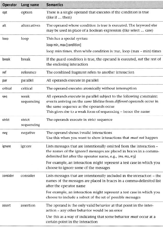
46 Summary of the syntax 46
47 Building sequence diagrams» Set the context» Identify participants that should interact to realize the use-case scenario / to respond to messages arriving at the interface. Place the initiator of the interaction on the left of the diagram Multiple objects of the same class: name each» Set the lifeline for each participant» Add messages by drawing arrows Order messages from left to right, top to bottom Show how they are passed from one object to another Include any parameters in parentheses Exclude obvious return values» Add activations to each participant s lifeline» Validate the sequence diagram / SET / W&I 26/02/15 47
![Validation» Recall: Interaction diagrams should be consistent with the corresponding class diagrams and use case diagrams» Rule: Objects in [sd] should be instances of classes in [cd]»](/docs-images/93/113542434/images/48-0.jpg "Rule: Name of the message [sd] should match an operation in the receiver s class [cd] ATM +withdrawcash(accountnumber, amount) http://www.ibm.com/developerworks/rational/library/3101.")
48 Validation» Recall: Interaction diagrams should be consistent with the corresponding class diagrams and use case diagrams» Rule: Objects in [sd] should be instances of classes in [cd]» Rule: Name of the message [sd] should match an operation in the receiver s class [cd] ATM +withdrawcash(accountnumber, amount) 48
49 Validation» Recall: Interaction diagrams should be consistent with the corresponding class diagrams and use case diagrams» Rule: Objects in [sd] should be instances of classes in [cd]» Rule: Name of the message [sd] should match an operation in the receiver s class [cd] The message is a getter! +name Girl 49
50 Validation» Recall: Interaction diagrams should be consistent with the corresponding class diagrams and use case diagrams» Rule: Objects in [sd] should be instances of classes in [cd]» Rule: Name of the message [sd] should match an operation in the receiver s class [cd]» Rule: If a message is sent from A to B [sd] then there should be an association from the class of A to the class of B [cd]» Rule: If use-case A generalizes use-case B [ucd] then the sequence diagram of A should be a subgraph of the sequence diagram of B [sd]. 50
51 Validation» Recall: Interaction diagrams should be consistent with the corresponding class diagrams and use case diagrams» Briand et al. mention 120 consistency rules TR_SCE pdf» Active research domain around 2005 Prototype implementations Inconsistency detection vs. inconsistency resolution 51
52 UML diagram types: so far / SET / W&I 26/02/15 52
The learning objectives of this chapter are the followings. At the end of this chapter, you shall
 Chapter 5 Sequence diagrams In the previous chapters, we have seen different diagrams. Use case diagrams describe tasks that a system is supposed to perform. It gives high-level information about how a
Object-Oriented Modeling. Sequence Diagram. Slides accompanying Version 1.0
 Object-Oriented Modeling Sequence Diagram Slides accompanying UML@Classroom Version 1.0 Business Informatics Group Institute of Software Technology and Interactive Systems Vienna University of Technology
Sequence Diagrams. Massimo Felici. Massimo Felici Sequence Diagrams c
 Sequence Diagrams Massimo Felici What are Sequence Diagrams? Sequence Diagrams are interaction diagrams that detail how operations are carried out Interaction diagrams model important runtime interactions
Object-Interaction Diagrams: Sequence Diagrams UML
 Object-Interaction Diagrams: Sequence Diagrams UML Communication and Time In communication diagrams, ordering of messages is achieved by labelling them with sequence numbers This does not make temporal
Unified Modeling Language
 Unified Modeling Language Software technology Szoftvertechnológia Dr. Balázs Simon BME, IIT Outline UML Diagrams: Sequence Diagram Communication Diagram Interaction Overview Diagram Dr. Balázs Simon, BME,
Object Interaction Sequence Diagrams
 Object Interaction Sequence Diagrams Based on Chapter 9 Bennett, McRobb and Farmer Object Oriented Systems Analysis and Design Using UML 4 th Edition, McGraw Hill, 2010 2010 Bennett, McRobb and Farmer
Introduction to Unified Modelling Language (UML)
") IMPORTANT NOTICE TO STUDENTS These slides are NOT to be used as a replacement for student notes. These slides are sometimes vague and incomplete on purpose to spark a class discussion Introduction to Unified
IMPORTANT NOTICE TO STUDENTS These slides are NOT to be used as a replacement for student notes. These slides are sometimes vague and incomplete on purpose to spark a class discussion Introduction to Unified
Interaction Modelling: Sequence Diagrams
 Interaction Modelling: Sequence Diagrams Fabrizio Maria Maggi Institute of Computer Science (these slides are derived from the book Object-oriented modeling and design with UML ) Interaction Modelling
What is a Class Diagram? A diagram that shows a set of classes, interfaces, and collaborations and their relationships
 Class Diagram What is a Class Diagram? A diagram that shows a set of classes, interfaces, and collaborations and their relationships Why do we need Class Diagram? Focus on the conceptual and specification
What is a Class Diagram? Class Diagram. Why do we need Class Diagram? Class - Notation. Class - Semantic 04/11/51
 What is a Class Diagram? Class Diagram A diagram that shows a set of classes, interfaces, and collaborations and their relationships Why do we need Class Diagram? Focus on the conceptual and specification
UML Behavioral Models
 UML Behavioral Models Dept. of Computer Science Baylor University Some slides adapted from materials in the following sources: UMLTutorial by Dr. R. France, Lecture slides by Dr. C. Constantinides Specifying
In this case, the behavior of a single scenario
 CPSC 491 UML Sequence s UML Sequence s One of many UML notations for modeling behavior A specific type of interaction diagram In this case, the behavior of a single scenario Usually a single call on an
Lecture 21 Detailed Design Dynamic Modeling with UML
 Lecture 21 Detailed Design Dynamic Modeling with UML Software Engineering ITCS 3155 Fall 2008 Dr. Jamie Payton Department of Computer Science University of North Carolina at Charlotte November 18, 2008
3: Modeling Behavior with UML Sequence Diagrams
 Outline UML Design Supplement 3: Modeling Behavior with UML Sequence Diagrams Introduction Basic notation Alternating paths Modularity Slide adapted from Eran Toch s lecture series Specification and Analysis
CS 370 REVIEW: UML Diagrams D R. M I C H A E L J. R E A L E F A L L
 CS 370 REVIEW: UML Diagrams D R. M I C H A E L J. R E A L E F A L L 2 0 1 5 Introduction UML Unified Modeling Language Very well recognized specification for modeling architectures, use cases, etc. UML
UML Sequence Diagrams
 UML Sequence Diagrams Prof. Dr. Eric Dubuis Berner Fachhochschule, @ Biel Course "UML and Design Patterns" of module "Software Engineering and Design", version October 2008 BFH/TI/Software Engineering
Object Oriented Methods with UML. Lecture -4
 Object Oriented Methods with UML Lecture -4 Topics Class diagram with sample code Interaction diagram Sequence Diagram Collaboration Diagram Class Diagram with sample code +name: char #email: char #CNumber:
CSE 403. UML Sequence Diagrams. Reading: UML Distilled Ch. 4, by M. Fowler
 CSE 403 UML Sequence Diagrams Reading: UML Distilled Ch. 4, by M. Fowler These lecture slides are copyright (C) Marty Stepp, 2007. They may not be rehosted, sold, or modified without expressed permission
Class diagrams. Modeling with UML Chapter 2, part 2. Class Diagrams: details. Class diagram for a simple watch
 Class diagrams Modeling with UML Chapter 2, part 2 CS 4354 Summer II 2015 Jill Seaman Used to describe the internal structure of the system. Also used to describe the application domain. They describe
Meltem Özturan
 Meltem Özturan www.mis.boun.edu.tr/ozturan/samd 1 2 Modeling System Requirements Object Oriented Approach to Requirements OOA considers an IS as a set of objects that work together to carry out the function.
KF5008 Program Design & Development. Lecture 3 Sequence Diagrams
 KF5008 Program Design & Development Lecture 3 Sequence Diagrams Learning Outcomes At the end of the lecture, you should be able to: Explain the content and purpose of a UML Sequence Diagram Describe the
Software Specification 2IX20
 Software Specification 2IX20 Julien Schmaltz (slides from A. Serebrenik) Lecture 06: (Behavioural diagrams) Activity diagrams and state machines Instructions - Status» Low interest in passive sessions
Chapter 2, Modeling with UML: UML 2 Hightlights
 Object-Oriented Software Engineering Using UML, Patterns, and Java Chapter 2, Modeling with UML: UML 2 Hightlights Outline for this class ü Overview of important changes in UML 2 Ø Deployment diagrams
Interactions A link message
 Interactions An interaction is a behavior that is composed of a set of messages exchanged among a set of objects within a context to accomplish a purpose. A message specifies the communication between
CSE 308. UML Sequence Diagrams. Reading / Reference.
 CSE 308 UML Sequence Diagrams Reading Reading / Reference www.ibm.com/developerworks/rational/library/3101.html Reference www.visual-paradigm.com/vpgallery/diagrams/sequence.html 2 1 Interaction Diagrams
Use Case Sequence Diagram. Slide 1
 Use Case Sequence Diagram Slide 1 Interaction Diagrams l Interaction diagrams model the behavior of use cases by describing the way groups of objects interact to complete the task of the use case. They
Unified Modeling Language (UML) Object Diagram and Interaction Diagrams
 Object Diagram and Interaction Diagrams") 1 / 17 Unified Modeling Language (UML) and Miaoqing Huang University of Arkansas Spring 2010 2 / 17 Outline 1 2 3 / 17 Outline 1 2 4 / 17 A snapshot of the objects in a system at a point in time Object:
1 / 17 Unified Modeling Language (UML) and Miaoqing Huang University of Arkansas Spring 2010 2 / 17 Outline 1 2 3 / 17 Outline 1 2 4 / 17 A snapshot of the objects in a system at a point in time Object:
INTRODUCTION TO UNIFIED MODELING MODEL (UML) & DFD. Slides by: Shree Jaswal
 & DFD. Slides by: Shree Jaswal") INTRODUCTION TO UNIFIED MODELING MODEL (UML) & DFD Slides by: Shree Jaswal What is UML? 2 It is a standard graphical language for modeling object oriented software. It was developed in mid 90 s by collaborative
INTRODUCTION TO UNIFIED MODELING MODEL (UML) & DFD Slides by: Shree Jaswal What is UML? 2 It is a standard graphical language for modeling object oriented software. It was developed in mid 90 s by collaborative
Modeling Dynamic Behavior
 Dr. Michael Eichberg Software Engineering Department of Computer Science Technische Universität Darmstadt Software Engineering Modeling Dynamic Behavior The following slides use material from: Craig Larman;
Specifying Precise Use Cases with Use Case Charts
 Specifying Precise Use Cases with Use Case Charts Jon Whittle Dept of Information & Software Engineering George Mason University 4400 University Drive Fairfax, VA 22030 jwhittle@ise.gmu.edu Abstract. Use
Time Exceptions in Sequence Diagrams
 in Sequence Diagrams Oddleif Halvorsen, Ragnhild Kobro Runde, Øystein Haugen 02-Oct-2006 MARTES 2006 at MoDELS 2006 1 Summary Introducing time exceptions improve the completeness of sequence diagram descriptions
Requirements Checking for Object-Oriented Software Design with different Unified Modelling Language (UML) notations
 notations") Requirements Checking for Object-Oriented Software Design with different Unified Modelling Language (UML) notations Use Case Notation, Sequence Diagrams, Regular Expressions and State Automata Bart Meyers
Requirements Checking for Object-Oriented Software Design with different Unified Modelling Language (UML) notations Use Case Notation, Sequence Diagrams, Regular Expressions and State Automata Bart Meyers
Sequence Diagram. r: Register s: Sale
 ACS-3913 1 Sequence Diagram A UML diagram used to show how objects interact. Example: r: Register s: Sale makepayment() makepayment() new() : Payment The above starts with a Register object, r, receiving
Sequence Diagram. A UML diagram used to show how objects interact. Example:
 Sequence Diagram A UML diagram used to show how objects interact. Example: r: Register s: Sale makepayment() makepayment() new() : Payment The above starts with a Register object, r, receiving a makepayment
Distributed Systems. Lec 11: Consistency Models. Slide acks: Jinyang Li, Robert Morris
 Distributed Systems Lec 11: Consistency Models Slide acks: Jinyang Li, Robert Morris (http://pdos.csail.mit.edu/6.824/notes/l06.txt, http://www.news.cs.nyu.edu/~jinyang/fa09/notes/ds-consistency.pdf) 1
Unit 5: Sequence Diagrams
 1 TTM4115 Design of Reactive Systems 1 Spring 2018 Frank lexander Kraemer, kraemer@ntnu.no Unit 5: Sequence Diagrams Why do we need sequence diagrams? State machines are suitable to show the behavior of
Reminder from last time
 Concurrent systems Lecture 5: Concurrency without shared data, composite operations and transactions, and serialisability DrRobert N. M. Watson 1 Reminder from last time Liveness properties Deadlock (requirements;
CS211 Lecture: Modeling Dynamic Behaviors of Systems; Interaction Diagrams in UML
 CS211 Lecture: Modeling Dynamic Behaviors of Systems; Interaction Diagrams in UML Objectives: 1. To introduce the notion of dynamic analysis 2. To show how to create and read Sequence Diagrams 3. To show
UML Fundamental. OutLine. NetFusion Tech. Co., Ltd. Jack Lee. Use-case diagram Class diagram Sequence diagram
 UML Fundamental NetFusion Tech. Co., Ltd. Jack Lee 2008/4/7 1 Use-case diagram Class diagram Sequence diagram OutLine Communication diagram State machine Activity diagram 2 1 What is UML? Unified Modeling
UNIT 3
 UNIT 3 Presentation Outline Sequence control with expressions Conditional Statements, Loops Exception Handling Subprogram definition and activation Simple and Recursive Subprogram Subprogram Environment
UML 2.0 UML 2.0. Scott Uk-Jin Lee. Division of Computer Science, College of Computing Hanyang University ERICA Campus
 UML 2.0 Division of Computer Science, College of Computing Hanyang University ERICA Campus Introduction to UML 2.0 UML Unified Modeling Language Visual language for specifying, constructing and documenting
A Logical Framework for Sequence Diagram with Combined Fragments
 A Logical Framework for Sequence Diagram with Combined Fragments Hui Shen, Mark Robinson and Jianwei Niu Department of Computer Science University of Texas at San Antonio One UTSA Circle, San Antonio,
Class diagrams. Modeling with UML Chapter 2, part 2. Class Diagrams: details. Class diagram for a simple watch
 Class diagrams Modeling with UML Chapter 2, part 2 CS 4354 Summer II 2014 Jill Seaman Used to describe the internal structure of the system. Also used to describe the application domain. They describe
Relationships between UML Sequence Diagrams and the Topological Functioning Model for Backward Transformation
 2014/16 Relationships between UML Sequence Diagrams and the Topological Functioning Model for Backward Transformation Viktoria Ovchinnikova 1, Erika Asnina 2, Vicente García-Díaz 3, 1 2 Riga Technical
UNIT-4 Behavioral Diagrams
 UNIT-4 Behavioral Diagrams P. P. Mahale Behavioral Diagrams Use Case Diagram high-level behaviors of the system, user goals, external entities: actors Sequence Diagram focus on time ordering of messages
Sequence Diagrams. Sequence Diagrams. Version Sequence Diagrams are. History. simple powerful readable used to describe interaction sequences
 Sequence Diagrams Version 020913 INF-UIT 2002 / Basic Sequence Diagrams / Slide 1 Sequence Diagrams Sequence Diagrams are simple powerful readable used to describe interaction sequences History Has been
Refining UML specifications. - the STAIRS method. Ragnhild Kobro Runde. Joint work with Ketil Stølen and Øystein Haugen. Ragnhild Kobro Runde
 Refining UML specifications - the STAIRS method Joint work with Ketil Stølen and Øystein Haugen SARDAS-seminar 21.05.2008 / Refining UML specifications / Slide 1 Outline Introduction to sequence diagrams.
UML Sequence Diagrams for Process Views
 UML Sequence Diagrams for Process Views With some material from MartyStepp lectures, Wi07. Outline UML class diagrams recap UML sequence diagrams UML wrapup More detail: http://dn.codegear.com/article/31863#sequence-diagrams
CS211 Lecture: Modeling Dynamic Behaviors of Systems; Interaction Diagrams and Statecharts Diagrams in UML
 CS211 Lecture: Modeling Dynamic Behaviors of Systems; Interaction Diagrams and Statecharts Diagrams in UML Objectives: 1. To introduce the notion of dynamic analysis 2. To show how to create and read Sequence
introduction to Programming in C Department of Computer Science and Engineering Lecture No. #40 Recursion Linear Recursion
 introduction to Programming in C Department of Computer Science and Engineering Lecture No. #40 Recursion Linear Recursion Today s video will talk about an important concept in computer science which is
Software Modeling & Analysis
 Software Modeling & Analysis OOPT (Object Oriented Process with Trace) Lecturer: JUNBEOM YOO jbyoo@konkuk.ac.kr What is OOPT? OOPT (Object Oriented Process with Trace) A software process based on RUP Revision
SEEM4570 System Design and Implementation Lecture 11 UML
 SEEM4570 System Design and Implementation Lecture 11 UML Introduction In the previous lecture, we talked about software development life cycle in a conceptual level E.g. we need to write documents, diagrams,
Process Modelling. Fault Tolerant Systems Research Group. Budapest University of Technology and Economics
 Process Modelling Budapest University of Technology and Economics Fault Tolerant Systems Research Group Budapest University of Technology and Economics Department of Measurement and Information Systems
UNIT I. 3. Write a short notes on process view of 4+1 architecture. 4. Why is object-oriented approach superior to procedural approach?
 Department: Information Technology Questions Bank Class: B.E. (I.T) Prof. Bhujbal Dnyaneshwar K. Subject: Object Oriented Modeling & Design dnyanesh.bhujbal11@gmail.com ------------------------------------------------------------------------------------------------------------
Today s Agenda UML. CompSci 280 S Introduction to Software Development. 1.Introduction UML Diagrams. Topics: Reading:
 CompSci 280 S2 2107 Introduction to Software Development Today s Agenda Topics: Introduction Activity Diagram Object interaction Sequence Diagram Reading: Booch G.,The Unified Modeling Language User Guide,
UNIT-IV BASIC BEHAVIORAL MODELING-I
 UNIT-IV BASIC BEHAVIORAL MODELING-I CONTENTS 1. Interactions Terms and Concepts Modeling Techniques 2. Interaction Diagrams Terms and Concepts Modeling Techniques Interactions: Terms and Concepts: An interaction
Distributed minimum spanning tree problem
 Distributed minimum spanning tree problem Juho-Kustaa Kangas 24th November 2012 Abstract Given a connected weighted undirected graph, the minimum spanning tree problem asks for a spanning subtree with
Chapter 10. Object-Oriented Analysis and Modeling Using the UML. McGraw-Hill/Irwin
 Chapter 10 Object-Oriented Analysis and Modeling Using the UML McGraw-Hill/Irwin Copyright 2007 by The McGraw-Hill Companies, Inc. All rights reserved. Objectives 10-2 Define object modeling and explain
Applying UML & Patterns (3 rd ed.) Chapter 15
 Chapter 15") Applying UML & Patterns (3 rd ed.) Chapter 15 UML INTERACTION DIAGRAMS This document may not be used or altered without the express permission of the author. Dr. Glenn L. Ray School of Information Sciences
Applying UML & Patterns (3 rd ed.) Chapter 15 UML INTERACTION DIAGRAMS This document may not be used or altered without the express permission of the author. Dr. Glenn L. Ray School of Information Sciences
Review of the C Programming Language
 Review of the C Programming Language Prof. James L. Frankel Harvard University Version of 11:55 AM 22-Apr-2018 Copyright 2018, 2016, 2015 James L. Frankel. All rights reserved. Reference Manual for the
Modeling Dynamic Behavior
 Dr. Michael Eichberg Software Engineering Department of Computer Science Technische Universität Darmstadt Software Engineering Modeling Dynamic Behavior The following slides use material from: Craig Larman;
6.001 Notes: Section 8.1
 6.001 Notes: Section 8.1 Slide 8.1.1 In this lecture we are going to introduce a new data type, specifically to deal with symbols. This may sound a bit odd, but if you step back, you may realize that everything
State Machine Diagrams
 State Machine Diagrams Introduction A state machine diagram, models the dynamic aspects of the system by showing the flow of control from state to state for a particular class. 2 Introduction Whereas an
UML part I. UML part I 1/41
 UML part I UML part I 1/41 UML part I 2/41 UML - Unified Modeling Language unified it can be shared among workers modeling it can be used for description of software model language it has defined structure
Ingegneria del Software Corso di Laurea in Informatica per il Management
 Ingegneria del Software Corso di Laurea in Informatica per il Management UML: State machine diagram Davide Rossi Dipartimento di Informatica Università di Bologna State machine A behavioral state machine
Use C ases Cases 7/09
 Use Cases 7/09 Groups of 3 Recorder/Timekeeper Participation checker Devil s Advocate Motivation One way to describe a system is to create a story, y, the interaction between a user and the system This
Object-Oriented Principles and Practice / C++
 Object-Oriented Principles and Practice / C++ Alice E. Fischer April 20, 2015 OOPP / C++ Lecture 3... 1/23 New Things in C++ Object vs. Pointer to Object Optional Parameters Enumerations Using an enum
CS4961 Parallel Programming. Lecture 4: Data and Task Parallelism 9/3/09. Administrative. Mary Hall September 3, Going over Homework 1
 CS4961 Parallel Programming Lecture 4: Data and Task Parallelism Administrative Homework 2 posted, due September 10 before class - Use the handin program on the CADE machines - Use the following command:
Lecture 17: (Architecture V)
") Lecture 17: (Architecture V) Software System Design and Implementation ITCS/ITIS 6112/8112 091 Fall 2008 Dr. Jamie Payton Department of Computer Science University of North Carolina at Charlotte Oct. 30,
Lecture 17: (Architecture V) Software System Design and Implementation ITCS/ITIS 6112/8112 091 Fall 2008 Dr. Jamie Payton Department of Computer Science University of North Carolina at Charlotte Oct. 30,
Software Engineering. Page 1. Objectives. Object-Behavioural Modelling. Analysis = Process + Models. Case Study: Event Identification
 Software Engineering Object-Oriented Analysis (State and Interaction Diagrams) James Gain (jgain@cs.uct.ac.za) http://people.cs.uct.ac.za/~jgain 1. Show the object-behaviour design process Objectives 2.
Lesson 11. W.C.Udwela Department of Mathematics & Computer Science
 Lesson 11 INTRODUCING UML W.C.Udwela Department of Mathematics & Computer Science Why we model? Central part of all the activities We build model to Communicate Visualize and control Better understand
Object Oriented Modeling
 Overview UML Unified Modeling Language What is Modeling? What is UML? A brief history of UML Understanding the basics of UML UML diagrams UML Modeling tools 2 Modeling Object Oriented Modeling Describing
What's New in UML 2.0
 What's New in UML 2.0 M.W.Richardson Lead Applications Engineer I-Logix UK mrichardson@ilogix.com What is UML? Unified Modeling Language Comprehensive full life-cycle 3 rd Generation modeling language
Draw a diagram of an empty circular queue and describe it to the reader.
 1020_1030_testquestions.text Wed Sep 10 10:40:46 2014 1 1983/84 COSC1020/30 Tests >>> The following was given to students. >>> Students can have a good idea of test questions by examining and trying the
System Sequence Diagrams. Based on Craig Larman, Chapter 10 and Anuradha Dharani s notes
 System Sequence Diagrams Based on Craig Larman, Chapter 10 and Anuradha Dharani s notes Dynamic behaviors Class diagrams represent static relationships. Why? What about modeling dynamic behavior? Interaction
Run-time Environments. Lecture 13. Prof. Alex Aiken Original Slides (Modified by Prof. Vijay Ganesh) Lecture 13
 Lecture 13") Run-time Environments Lecture 13 by Prof. Vijay Ganesh) Lecture 13 1 What have we covered so far? We have covered the front-end phases Lexical analysis (Lexer, regular expressions,...) Parsing (CFG, Top-down,
Run-time Environments Lecture 13 by Prof. Vijay Ganesh) Lecture 13 1 What have we covered so far? We have covered the front-end phases Lexical analysis (Lexer, regular expressions,...) Parsing (CFG, Top-down,
Object-Oriented Software Engineering Practical Software Development using UML and Java
 Object-Oriented Software Engineering Practical Software Development using UML and Java Chapter 5: Modelling with Classes Lecture 5 5.1 What is UML? The Unified Modelling Language is a standard graphical
SEEM4570 System Design and Implementation. Lecture 10 UML
 SEEM4570 System Design and Implementation Lecture 10 UML Introduction In the previous lecture, we talked about software development life cycle in a conceptual level E.g. we need to write documents, diagrams,
COMP 354: INTRODUCTION TO SOFTWARE ENGINEERING
 COMP 354: INTRODUCTION TO SOFTWARE ENGINEERING Introduction to UML d_sinnig@cs.concordia.ca Department for Computer Science and Software Engineering 28-May-14 Unified Modeling Language Structural Diagrams
6/20/2018 CS5386 SOFTWARE DESIGN & ARCHITECTURE LECTURE 5: ARCHITECTURAL VIEWS C&C STYLES. Outline for Today. Architecture views C&C Views
 1 CS5386 SOFTWARE DESIGN & ARCHITECTURE LECTURE 5: ARCHITECTURAL VIEWS C&C STYLES Outline for Today 2 Architecture views C&C Views 1 Components and Connectors (C&C) Styles 3 Elements Relations Properties
Introduction to Model Checking
 Introduction to Model Checking René Thiemann Institute of Computer Science University of Innsbruck WS 2007/2008 RT (ICS @ UIBK) week 4 1/23 Outline Promela - Syntax and Intuitive Meaning Promela - Formal
BASICS OF UML (PART-2)
") BASICS OF UML (PART-2) 1 USE CASE DIAGRAMS 2 USE CASE DIAGRAMS Use Case Model: a view of a system that emphasizes the behavior as it appears to outside users. A use case model partitions system functionality
BASICS OF UML (PART-2) 1 USE CASE DIAGRAMS 2 USE CASE DIAGRAMS Use Case Model: a view of a system that emphasizes the behavior as it appears to outside users. A use case model partitions system functionality
4/6/2011. Model Checking. Encoding test specifications. Model Checking. Encoding test specifications. Model Checking CS 4271
 Mel Checking LTL Property System Mel Mel Checking CS 4271 Mel Checking OR Abhik Roychoudhury http://www.comp.nus.edu.sg/~abhik Yes No, with Counter-example trace 2 Recap: Mel Checking for mel-based testing
Lecture 21 CIS 341: COMPILERS
 Lecture 21 CIS 341: COMPILERS Announcements HW6: Analysis & Optimizations Alias analysis, constant propagation, dead code elimination, register allocation Available Soon Due: Wednesday, April 25 th Zdancewic
Tool Support for Design Inspection: Automatic Generation of Questions
 Tool Support for Design Inspection: Automatic Generation of Questions Tim Heyer Department of Computer and Information Science, Linköping University, S-581 83 Linköping, Email: Tim.Heyer@ida.liu.se Contents
Computer Science for Engineers
 Computer Science for Engineers Lecture 5 Object Orientation part 3 Prof. Dr. Dr.-Ing. Jivka Ovtcharova Dipl. Wi.-Ing. Dan Gutu 27 th of November 2009 Aggregation and Composition (1) A special case of an
Software Design and Analysis for Engineers
 Software Design and Analysis for Engineers by Dr. Lesley Shannon Email: lshannon@ensc.sfu.ca Course Website: http://www.ensc.sfu.ca/~lshannon/courses/ensc251 Simon Fraser University Slide Set: 2 Date:
Enterprise Architect. User Guide Series. Testpoints. Author: Sparx Systems. Date: 30/06/2017. Version: 1.0 CREATED WITH
 Enterprise Architect User Guide Series Testpoints Author: Sparx Systems Date: 30/06/2017 Version: 1.0 CREATED WITH Table of Contents Testpoints 3 Test Domain Diagram 7 Test Cut 9 Test Set 10 Test Suite
CSE P 501 Exam 8/5/04
 Name There are 7 questions worth a total of 65 points. Please budget your time so you get to all of the questions. Keep your answers brief and to the point. You may refer to the following references: Course
Advanced Interaction
 8 Advanced nteraction Modeling The interaction model has several advanced features that can be helpful. You can skip this chapter on a first reading of the book. 8.1 Use Case Relationships ndependent use
Model-based Behavioural Fuzzing. Martin Schneider (Fraunhofer FOKUS)
") Model-based Behavioural Fuzzing Martin Schneider (Fraunhofer FOKUS) Outline Introduction to fuzzing Behavioural fuzzing of UML sequence diagrams Test case selection by augmenting the model Conclusions
Model-based Behavioural Fuzzing Martin Schneider (Fraunhofer FOKUS) Outline Introduction to fuzzing Behavioural fuzzing of UML sequence diagrams Test case selection by augmenting the model Conclusions
PROCESSES AND THREADS
 PROCESSES AND THREADS A process is a heavyweight flow that can execute concurrently with other processes. A thread is a lightweight flow that can execute concurrently with other threads within the same
Process Modelling. Fault Tolerant Systems Research Group. Budapest University of Technology and Economics
 Process Modelling Budapest University of Technology and Economics Fault Tolerant Systems Research Group Budapest University of Technology and Economics Department of Measurement and Information Systems
Model Based Software Timing Analysis Using Sequence Diagram for Commercial Applications
 IOSR Journal of Computer Engineering (IOSR-JCE) e-issn: 2278-0661,p-ISSN: 2278-8727, Volume 17, Issue 3, Ver. 1 (May Jun. 2015), PP 17-24 www.iosrjournals.org Model Based Software Timing Analysis Using
7. UML Sequence Diagrams Page 1 of 1
 7. UML Sequence Diagrams Page 1 of 1 Sequence Diagram in UML In the last article, we saw Activity diagrams, the notations to be used in Activity diagrams, their significance, and how to build an Activity
Notes on the Exam. Question 1. Today. Comp 104:Operating Systems Concepts 11/05/2015. Revision Lectures (separate questions and answers)
") Comp 104:Operating Systems Concepts Revision Lectures (separate questions and answers) Today Here are a sample of questions that could appear in the exam Please LET ME KNOW if there are particular subjects
Comp 104:Operating Systems Concepts Revision Lectures (separate questions and answers) Today Here are a sample of questions that could appear in the exam Please LET ME KNOW if there are particular subjects
Software Engineering using Formal Methods
 Software Engineering using Formal Methods Introduction to Promela Wolfgang Ahrendt 03 September 2015 SEFM: Promela /GU 150903 1 / 36 Towards Model Checking System Model Promela Program byte n = 0; active
COSC 3351 Software Design. An Introduction to UML (I)
") COSC 3351 Software Design An Introduction to UML (I) This lecture contains material from: http://wps.prenhall.com/esm_pfleeger_softengtp_2 http://sunset.usc.edu/classes/cs577a_2000/lectures/05/ec-05.ppt
COSC 3351 Software Design An Introduction to UML (I) This lecture contains material from: http://wps.prenhall.com/esm_pfleeger_softengtp_2 http://sunset.usc.edu/classes/cs577a_2000/lectures/05/ec-05.ppt
G Programming Languages - Fall 2012
 G22.2110-003 Programming Languages - Fall 2012 Lecture 4 Thomas Wies New York University Review Last week Control Structures Selection Loops Adding Invariants Outline Subprograms Calling Sequences Parameter
Semantics Preservation of Sequence
 Semantics Preservation of Sequence Diagram Aspects Jon Oldevik, Øystein Haugen Department of Informatics, University of Oslo, Norway SINTEF Information and Communication Technology, Norway jonold at ifi.uio.no