MP2000 Series Function Block Details
|
|
|
- Mark Carson
- 6 years ago
- Views:
Transcription
1 MP2000 Series Function Block Details Please click a Function Block to jump to the details. Motion Blocks AXISEND CAM CAM_RECV CAMOFFST CAMSCALE CHNG_DYN GEAR HOME LATCH LTHTRGT MOD_ENG MOVABS MOVADDTV MOVINC MOVVEL SLAVEOFF STOP SVON TUNING Administrative Blocks AENC_RST ALRMRST DEF_POS RDAINIT1 RDAINIT2 RDERROR RDPARAM WRTPARAM I/O Blocks ASCIIIN ASCIIOUT PLS File: MP2000_IndividualFunctionDocument_RevC 1/168 Doc Number: EF.MCD /17/2005

2 Revision Level As part of best practices, it is advised to keep track of the revision level of each function block for the ease of technical support and maintenance. Each block has a revision number that is defined in the first rung of function code. This value must be altered if the block is modified. The number is broken into two parts as follows. Revision Number format: XXYY XX = Revision by Yaskawa engineering and registered YY - Revision by Non Yaskawa personnel and unregistered changes The revision number uses an A register to allow the value to be monitored. The revision level can be determined by looking at the last word from the base address including the base address, the revision can be seen. If it is necessary to replace a function block with a newer revision, simply import the newer function block over the existing version. Doing this may clear all of the I/O fields. If this occurs, simply re-enter the input and output data into the block, then save and verify the project. File: MP2000_IndividualFunctionDocument_RevC 2/168 Doc Number: EF.MCD /17/2005

3 AXIS END function Function block for MP2000 series <AXISEND> Function Block Summary This function block writes necessary values to the RDA at the end of the motion scan cycle. This block is essential if any of the Blocks in the set are to be used. Function Block Diagram <AXISEND> Function Block Operation Note NOTE: SVON and AXISEND blocks must be used together, all motion type blocks for a specific axis must be placed between the SVON and AXISEND blocks. This block must be used in the High Speed Scan drawings, and should be the last block executed after all other motion function blocks within the scan. This block writes values from RDA to specific axis control registers required for controlling motion. This block was created to reduce the overall volume of code in all other function blocks for multi axis. It handles circuit number and axis number within the circuit, and relates it to the logical axis number selected by the programmer from the RDAINIT blocks. Example: for axis #1, this block writes to OW8000 RUN mode, OW8003, the unit selection, OW8004 latch demand detection signal selection, OW8005 home position return, OW8008 motion command code, OW8009 motion command control flag, OL8010 speed reference, OL801C positioning command, OL802A latch zone lower limit of the interval setting, OL802C latch zone upper limit setting, OL8036 acceleration time, OL8038 deceleration time, (see RDA matrix for details) This block also writes to ERRORID1 and ERRORID2 One word is used as working registers for this function, starting at the address in Data01W. File: MP2000_IndividualFunctionDocument_RevC 3/168 Doc Number: EF.MCD /17/2005
4 <AXISEND> Input and Output Register Map Output Registers The following registers are used from the function block as an output. To check the execution of the function, they can be monitored by the MPE720 program. Output Type Description ERROR bit If an error occurs during block execution, this output bit turns ON, but will reset if error condition goes away. Input Registers The following registers are used to block the function as an input. It is necessary to select the option, define the parameter, and make these function if necessary by the user. Input Type Description Range and state AXIS Word Axis number related to the 1~16 block. <AXISEND> Block Fault Condition: The following table outlines several situations that may cause an error. The block error can be cleared by the ENABLE bit going low. Error bit of internal Cause Attention The axis number entered on the input is not an acceptable value axisinerr ZB Function blocks can only control 1 to 16 axes. Any value greater or smaller then this will cause an error. This does not set the RDA Error ID. <AXISEND> Working Registers This table outlines the data in the registers used by the function block. There is not usually any need for the user to access any of these bits directly. Register No TYPE Name Content AW00000 Working Revision Revision Level of the function block. File: MP2000_IndividualFunctionDocument_RevC 4/168 Doc Number: EF.MCD /17/2005

5 CAM function Function block for MP2000 series <CAM> Function Block Summary The Cam block is a state block, different from the PLCopen spec in order to take advantage of the power of the MP products. Master/Slave pair is a numeric input indicating the master/slave source data from the Modulus Engine, and for the Cam Offset, Slave Offset, and Cam Scale. This block will position the slave based on the position of the master and the cam table. To operate, this block must have a Modulus Engine function block associated with the master/slave pair defined, to provide modulated master data. Slave offset, Cam offset, and Cam Scale function blocks can be used to make this block more flexible. Function Block Diagram File: MP2000_IndividualFunctionDocument_RevC 5/168 Doc Number: EF.MCD /17/2005
6 <CAM> Function Block Operation Notes IMPORTANT NOTE: If the CamScale value in the RDA (ML56**8) is zero the slave will not move. Slave Offset, Cam Scale, Cam Offset, Mod Engine, and Change Dynamics function blocks may be useful when using this block. ENABLE: Rising edge of the ENABLE input initiates block operation, and several block input values will be read once. These inputs are: AXIS, MSTRSLAV, TBLTYPE, TBLADDRS. This event will also verify & set the accel & decel values in the servopack to zero, to guarantee tight response. Note that this only means that the MP controller will control the accel/decel rates as defined in the CAM Table Profile (and the servopack will not limit the accel/decel). ENABLE: If the ENABLE input goes off during operation, the block will stop operating and the axis will immediately hold on its last commanded position from the Cam table. Warning: This can cause a rapid deceleration, which may damage machine mechanisms! CAMIN: While ENABLE input is high, Rising edge of CAMIN input initiates camming operation, and ENGAGPOS input value is read. Slave will then wait to engage camming until the master reaches the engage position. STATE output will indicate the camming operation state. CAMOUT: While ENABLE input is high, Rising edge of CAMOUT input initiates cam stop operation, and DISENGAG input value is read. The slave axis will continue to cam until the disengage (DISENGAG) input position is reached by the master. Then the slave axis will hold on the position defined by the cam table referenced by the master disengage position. Speed: The maximum speed the slave axis can go is the Max speed, set in the RDA. If the master commands the slave to go faster then this speed, axis will travel at the max. speed, and will output and latch the ERROR output. Note that the slave will continue to cam. Master Data: Modulated master data (according to desired machine cycle), must come from the Mod Engine function block if CAMSCALE, CAMOFFST, or SLAVEOFF function blocks are used. See MOD_ENG function block. Scale: If the Cam Scale (ML56**8) value is 0 the slave will not move because this is a multiplier to the commanded position (1=0.01% ). See CAMSCALE function block. Master Offset: The Cam Offset from the RDA is used to shift the value of the master as it s position relates to the slave. See CAMOFFST function block. Slave Offset: The slave offset from the RDA is used to shift the slave as its position as it relates to the Cam table. See SLAVEOFF function block. File: MP2000_IndividualFunctionDocument_RevC 6/168 Doc Number: EF.MCD /17/2005
7 CAM Table: Cam table is expected to be in 32-bit long integer words. Hence, each CAM table master/slave pair entry will take up 4 16-bit regular words (two words for master, two words for slave). The first long word of every table contains the table size in points. Example of a cam table with 10 master/slave pairs consumes MW04000 thru MW04041 where ML04000=10, ML04002=first master position, ML04004=first slave position, ML04006=second master position, ML04038=tenth master position, ML04040=tenth slave position. The M register address range is Range of register: MW00000 to MW29999 (M-register limit is due to RDA) CW00000 to CW16382 (C-register limit is ) DW00000 to DW16382 (D-register limit is ) One-way vs Cyclic camming comment: If the first and last slave positions are identical then it is a cyclic cam, otherwise it is treated as a one-way cam, and the slave will be offset by the difference each end of profile is reached (this is to prevent it from jumping). Note that the master/slave pairs are separated by 50 words in the RDA (up to 10 pairs). Example: Master/Slave pair #1 starts at MW56000, Master/Slave pair #2 starts at MW56050, Master/Slave pair #3 starts at MW56100, etc Internal Operation1: This block uses Motion Command Code. When the master reaches the engage position, the output of the function generator (FGN) function is assumed to be the current position of the slave. Any error in these positions is placed into an offset to avoid motor jumping. The slave command position (position control mode) is updated each scan from the function generator (FGN) output multiplied by cam scale and shifted by the slave offset. The result is placed in OL**1C position command register for the slave axis Internal Operation2: Under normal operation, the camming block operates in Interpolation mode (OW**08=4). If a latch block is used to capture a latched position, the mode will be switched to Interpolation mode with latch (OW**08=6). After the latch occurs, the block is returned to standard Interpolation mode. This switching feature happens in the background without affecting intended slave camming motion Thirty-two words are used as working registers for this function, starting at the address in Data32W. File: MP2000_IndividualFunctionDocument_RevC 7/168 Doc Number: EF.MCD /17/2005
8 <CAM> Input and Output Register Map Output Registers The following registers are used as outputs from the function block. They can be monitored by the LadderWorks program to check the execution of the function. Output TYPE Content RUNNING Bit Bit goes on when slave is camming, and the slave is being controlled by the master (STATE = 2) ENDPROFI Bit Puts out a single scan high pulse every time it reaches the end of the cam profile in either direction. ERROR Bit This bit is latched ON when the EXECUTE input is high and an error occurred in the block. STATUS Word The State of the block 0 = Disengaged 1 = Waiting to engage 2 = Camming 4 = Disengaging File: MP2000_IndividualFunctionDocument_RevC 8/168 Doc Number: EF.MCD /17/2005
9 Input Registers The following registers are used as inputs to the function block. They select the options and define the parameters that the user needs to make the Home function work as necessary. Input Type Description Range and state ENABLE Bit Block enable Block cannot execute unless this is TRUE. CAMIN Bit Sets block to search for ENGAGE position in master. When reached axis begins camming CAMOUT Bit Sets block to search for DISENGAG position in master. When reached axis stops and holds. AXIS Word Axis number related to the block 1 to 16 M-S-PAIR Word Master Slave Pair as defined by the RDA TBLTYPE Word Defines what register type the cam table will be in. CAM table consists of 32-bit long integer words TBLADDRS Word Starting address number of the cam table. In case of D register table, this value is relative to the assigned data address at DATA31W. TBLADDRS+DATA31W = Actual Starting Address ENGAGPOS Long Master position in counts to start the slave camming DISENGAG Long Master position in counts to stop the slave camming DATA32W Address Address of the first working register. Rising Edge see operation notes TRUE Block enable FALSE Block disable RISING EDGE- initiates search for engage position and sets up for camming RISING EDGE- initiates search for disengage position and stops camming and holds when position is reached by master. 1 to 10 integer. This value is needed to match the value of the MOD-ENG function block. 1 = M registers 2 = C registers 3 = D registers 0~3276 If the end of the table is greater than 32767, the an error will be set. (The limit of M-reg is MW00000 to MW29999) 0 to the machine cycle value defined in the MOD-ENG block 0 to the machine cycle value defined in the MOD-ENG block Thirty-two words of register space are used by this function. File: MP2000_IndividualFunctionDocument_RevC 9/168 Doc Number: EF.MCD /17/2005
10 <CAM> Block Fault Condition The following table outlines several situations that may cause an error, and will turn on the blocks Error output bit. The block Error output will cleared if the EXECUTE bit goes low, but the Error ID (MW3**81 and MW3**82) will remain in the RDA. To reset the Error ID, use the Alarm Reset Function Block. Note that each axis has its own Error ID stored in its RDA axis section, offset by 200 for each axis. Example: Axis#1 stores to MW30181, Axis #20 stores to MW30381, etc (note that Master/Slave pair is irrelevant). Internal Fault bit msinrng AB ctinrng AB addrinrng AB msterr AB00001F Direr AB00001F CmndError AB00001E AxisInErr AB Cause Master/Slave pair input out of range Table type input is out of range. Final address of table is beyond the range of the register. Last value in Cam table is greater then machine cycle. Direction not allowed by SVON Another block took control of axis The axis number entered on the input is not an acceptable value Note Value on input must be from 1 to 10. If this bit goes low while execute is high an error will occur. This will also generate an error in the RDA at MB3**813 Value on input must be from 1 to 3. If this bit goes low while execute is high an error will occur. This will also generate an error in the RDA at MB3**813. Checks that final address of the table (Start address + size) does not exceed max register size (29999 for M, for D and C type registers). If this bit is low on the rising edge of execute an error will occur. This will also generate an error in the RDA at MB3**813. If the last master value in the cam table is greater then the machine cycle an error will occur. This will also generate an error in the RDA at MB3**81C. The direction commanded was not enabled by SVON function. This will also generate an error in the RDA at MB3**814. If another axis controlling block while this block is running. It will take control from this function. This does not set the RDA Error ID. The function blocks can only control 1 to 16 axis. Any value greater or smaller then this will cause an error. This does not set the RDA Error ID. File: MP2000_IndividualFunctionDocument_RevC 10/168 Doc Number: EF.MCD /17/2005
11 <CAM> Working Register This table outlines the data in the thirty-three registers used by the function block. There is not usually any need for the user to access any of these bits directly. Register No. Type Name Description AW00000 Bit 0 IN EXECUTE ENABLE input (XB000000) Bit 1 IN CamIn CAMIN input (XB000001) Bit 2 IN CamOut CAMOUT input (XB000002) Bit 3 Working mregister Indicates table is in M register. Bit 4 Working cregister Indicates table is in C register. Bit 5 Working dregister Indicates table is in D register. Bit 6 Working engaging On when waiting for master to reach engage position. Bit 7 OUT running Directly controls YB (RUNNING Output) Bit 8 OUT endoftrvl Directly controls YB (ENDPROFI Output) Bit 9 OUT Mistake Directly controls YB (ERROR Output) Bit A Working oneshota Reserved Bit B Working firstpass One shot coil for initializing axis when CAMIN input goes high. Bit C Working oneshotc Reserved Bit D IN runinit One shot coil for initializing axis when engage position is reached. Bit E IN oneshote Reserved Bit F Working oneshotf Reserved AW00001 Bit 0 Working msinrng Verifies Master/Slave input is in range. Bit 1 Working ctinrng Verifies Table Type input is in range. Bit 2 Working addrinrng Verifies that the entire Cam Table is in the register and did not go beyond the register limits. Bit 3 Working disengaging On when camming and CAMOUT input goes high. Bit 4 Working above_point Reserved Bit 5 Working d_abovepos Reserved Bit 6 Working oneway On when first and last value of cam table are not equal. Bit 7 Working exeinit One shot coil on for first pass of block being executed. Bit 8 Working disengaged One shot coil for when disengage position is reached and called for. Bit A Working mstrerr On if last master value in cam table is greater then master machine cycle. Bit B Working posout Reserved Bit C Working backwords Reserved Bit D Working negout Reserved File: MP2000_IndividualFunctionDocument_RevC 11/168 Doc Number: EF.MCD /17/2005
12 Bit E Working cmnderror One shot coil for when another block takes control from this block. Bit F Working direrr On if a direction is commanded that is not enabled by the SVON block. AW00002 Working mstr_slave MstrSlave [value of (XW00001) 1] AW00003 Working filter1 Temporary values used to filter bits. AW00004 OUT camstate Directly controls YW00001 (STATE Output). AW00005 Bit 0 Working axisinerr Goes high for one scan if Axis input is out of range. AL00006 Working yfirst First position of slave in Cam table. AL00008 Working ylast Last position of slave in Cam table. AL00010 Working xlast Last position of Master in Cam table. AL00012 Working lastaddress Final register address of Cam table. Working Tolerance value for engage and disengage AL00014 Window position. Divide XLAST by 120. IE this window is 0.8% of the machine cycle. AL00016 Working masterpos Value of Master after CAM shift. AL00018 Working engage_differe nce Distance from engage or disengage point. AL00020 Working base_slave_po s Reserved AL00022 Working fgnout Value returned from Cam table function generator AL00024 Working slave_pos_cm nd Reserved AL00026 Working deltay Difference between first and last slave position in table, used if it s a one-way cam to offset the slave AL00028 Working o pos_o Reserved AW00030 Working rdamult Value for address offset to locate proper RDA AW00031 Working Revision Revision Level of Block. File: MP2000_IndividualFunctionDocument_RevC 12/168 Doc Number: EF.MCD /17/2005

13 CAM RECOVERY function Function block for MP2000 series <CAM_RECV> Function Block Summary The Cam block is a state block, different from the PLCopen spec in order to take advantage of the power of the MP products. Master/Slave pair is a numeric input indicating the master/slave source data from the Modulus Engine, and for the Cam Offset, Slave Offset, and Cam Scale. This block will position the slave based on the position of the master and the cam table. To operate, this block must have a Modulus Engine function block associated with the master/slave pair defined, to provide modulated master data. Slave offset, Cam offset, and Cam Scale function blocks can be used to make this block more flexible. CAM_RECV function block has E-stop recovery capability in addition to the CAM Function Block. Function Block Diagram File: MP2000_IndividualFunctionDocument_RevC 13/168 Doc Number: EF.MCD /17/2005
14 <CAM_RECV> Function Block Operation Notes IMPORTANT NOTE: If the CamScale value in the RDA (ML56**8) is zero the slave will not move. Slave Offset, Cam Scale, Cam Offset, Mod Engine, and Change Dynamics function blocks may be useful when using this block. ENABLE: Rising edge of the ENABLE input initiates block operation, and several block input values will be read once. These inputs are: AXIS, MSTRSLAV, TBLTYPE, TBLADDRS. This event will also verify & set the accel & decel values in the servopack to zero, to guarantee tight response. Note that this only means that the MP controller will control the accel/decel rates as defined in the CAM Table Profile (and the servopack will not limit the accel/decel). ENABLE: If the ENABLE input goes off during operation, the block will stop operating and the axis will immediately hold on its last commanded position from the Cam table. Warning: This can cause a rapid deceleration, which may damage machine mechanisms! CAMIN: While ENABLE input is high, Rising edge of CAMIN input initiates camming operation, and ENGAGPOS input value is read. Slave will then wait to engage camming until the master reaches the engage position. STATE output will indicate the camming operation state. CAMOUT: While ENABLE input is high, Rising edge of CAMOUT input initiates cam stop operation, and DISENGAG input value is read. The slave axis will continue to cam until the disengage (DISENGAG) input position is reached by the master. Then the slave axis will hold on the position defined by the cam table referenced by the master disengage position. Speed: The maximum speed the slave axis can go is the Max speed, set in the RDA. If the master commands the slave to go faster then this speed, axis will travel at the max. speed, and will output and latch the ERROR output. Note that the slave will continue to cam. Master Data: Modulated master data (according to desired machine cycle), must come from the Mod Engine function block if CAMSCALE, CAMOFFST, or SLAVEOFF function blocks are used. See MOD_ENG function block. Scale: If the Cam Scale (ML56**8) value is 0 the slave will not move because this is a multiplier to the commanded position (1=0.01% ). See CAMSCALE function block. Master Offset: The Cam Offset from the RDA is used to shift the value of the master as it s position relates to the slave. See CAMOFFST function block. Slave Offset: The slave offset from the RDA is used to shift the slave as its position as it relates to the Cam table. See SLAVEOFF function block. File: MP2000_IndividualFunctionDocument_RevC 14/168 Doc Number: EF.MCD /17/2005
15 CAM Table: Cam table is expected to be in 32-bit long integer words. Hence, each CAM table master/slave pair entry will take up 4 16-bit regular words (two words for master, two words for slave). The first long word of every table contains the table size in points. Example of a cam table with 10 master/slave pairs consumes MW04000 thru MW04041 where ML04000=10, ML04002=first master position, ML04004=first slave position, ML04006=second master position, ML04038=tenth master position, ML04040=tenth slave position. The M register address range is Range of register: MW00000 to MW29999 (M-register limit is due to RDA) CW00000 to CW16382 (C-register limit is ) DW00000 to DW16382 (D-register limit is ) One-way vs Cyclic camming comment: If the first and last slave positions are identical then it is a cyclic cam, otherwise it is treated as a one-way cam, and the slave will be offset by the difference each end of profile is reached (this is to prevent it from jumping). Note that the master/slave pairs are separated by 50 words in the RDA (up to 10 pairs). Example: Master/Slave pair #1 starts at MW56000, Master/Slave pair #2 starts at MW56050, Master/Slave pair #3 starts at MW56100, etc Internal Operation1: This block uses Motion Command Code. When the master reaches the engage position, the output of the function generator (FGN) function is assumed to be the current position of the slave. Any error in these positions is placed into an offset to avoid motor jumping. The slave command position (position control mode) is updated each scan from the function generator (FGN) output multiplied by cam scale and shifted by the slave offset. The result is placed in OL**1C position command register for the slave axis Internal Operation2: Under normal operation, the camming block operates in Interpolation mode (OW**08=4). If a latch block is used to capture a latched position, the mode will be switched to Interpolation mode with latch (OW**08=6). After the latch occurs, the block is returned to standard Interpolation mode. This switching feature happens in the background without affecting intended slave camming motion Thirty-two words are used as working registers for this function, starting at the address in Data32W. E-Stop Condition: Control Power of both the Servo pack and the Controller are ON and Main power of the Servo Pack is OFF while CAM is engaged. E-Stop Recovery motion: The Slave axis moves to the designated position based on the current Master position at the speed set in the RECVSPD [counts/sec]. File: MP2000_IndividualFunctionDocument_RevC 15/168 Doc Number: EF.MCD /17/2005
16 <CAM_RECV> Input and Output Register Map Output Registers The following registers are used as outputs from the function block. They can be monitored by the LadderWorks program to check the execution of the function. Output TYPE Content RUNNING Bit Bit goes on when slave is camming, and the slave is being controlled by the master (STATE = 2) ENDPROFI Bit Puts out a single scan high pulse every time it reaches the end of the cam profile in either direction. ERROR Bit This bit is latched ON when the EXECUTE input is high and an error occurred in the block. ESTOPED Bit This bit is latched ON when E-Stop condition occurs while CAM is engaged. This bit will be OFF when ENABLE input is OFF or recovery motion is done. RECVRING Bit This bit is ON when the axis is in the recovery motion. STATUS Word The State of the block 0 = Disengaged 1 = Waiting to engage 2 = Camming 4 = Disengaging File: MP2000_IndividualFunctionDocument_RevC 16/168 Doc Number: EF.MCD /17/2005
17 Input Registers The following registers are used as inputs to the function block. They select the options and define the parameters that the user needs to make the Home function work as necessary. Input Type Description Range and state ENABLE Bit Block enable Block cannot execute unless this is TRUE. CAMIN Bit Sets block to search for ENGAGE position in master. When reached axis begins camming CAMOUT Bit Sets block to search for DISENGAG position in master. When reached axis stops and holds. RECOVRY Bit Start Recovery Motion when E- stop occurred. AXIS Word Axis number related to the block 1 to 16 M-S-PAIR Word Master Slave Pair as defined by the RDA TBLTYPE Word Defines what register type the cam table will be in. CAM table consists of 32-bit long integer words TBLADDRS Word Starting address number of the cam table. In case of D register table, this value is relative to the assigned data address at DATA31W. TBLADDRS+DATA31W = Actual Starting Address ENGAGPO S Long Master position in counts to start the slave camming DISENGAG Long Master position in counts to stop the slave camming DATA32W Addres s Address of the first working register. Rising Edge see operation notes TRUE Block enable FALSE Block disable RISING EDGE- initiates search for engage position and sets up for camming RISING EDGE- initiates search for disengage position and stops camming and holds when position is reached by master. RISING EDGE- initiates the recovery motion. 1 to 10 integer. This value is needed to match the value of the MOD-ENG function block. 1 = M registers 2 = C registers 3 = D registers 0~3276 If the end of the table is greater than 32767, the an error will be set. (The limit of M-reg is MW00000 to MW29999) 0 to the machine cycle value defined in the MOD-ENG block 0 to the machine cycle value defined in the MOD-ENG block Thirty-two words of register space are used by this function. File: MP2000_IndividualFunctionDocument_RevC 17/168 Doc Number: EF.MCD /17/2005
18 <CAM_RECV> Block Fault Condition The following table outlines several situations that may cause an error, and will turn on the blocks Error output bit. The block Error output will cleared if the EXECUTE bit goes low, but the Error ID (MW3**81 and MW3**82) will remain in the RDA. To reset the Error ID, use the Alarm Reset Function Block. Note that each axis has its own Error ID stored in its RDA axis section, offset by 200 for each axis. Example: Axis#1 stores to MW30181, Axis #20 stores to MW30381, etc (note that Master/Slave pair is irrelevant). Internal Cause Fault bit msinrng Master/Slave pair input AB out of range ctinrng AB addrinrng AB msterr AB00001A Direr AB00001F CmndError AB00001E AxisInErr AB Table type input is out of range. Final address of table is beyond the range of the register. Last value in Cam table is greater then machine cycle. Direction not allowed by SVON Another block took control of axis The axis number entered on the input is not an acceptable value Note Value on input must be from 1 to 10. If this bit goes low while execute is high an error will occur. This will also generate an error in the RDA at MB3**813 Value on input must be from 1 to 3. If this bit goes low while execute is high an error will occur. This will also generate an error in the RDA at MB3**813. Checks that final address of the table (Start address + size) does not exceed max register size (29999 for M, for D and C type registers). If this bit is low on the rising edge of execute an error will occur. This will also generate an error in the RDA at MB3**813. If the last master value in the cam table is greater then the machine cycle an error will occur. This will also generate an error in the RDA at MB3**81C. The direction commanded was not enabled by SVON function. This will also generate an error in the RDA at MB3**814. If another axis controlling block while this block is running. It will take control from this function. This does not set the RDA Error ID. The function blocks can only control 1 to 16 axis. Any value greater or smaller then this will cause an error. This does not set the RDA Error ID. File: MP2000_IndividualFunctionDocument_RevC 18/168 Doc Number: EF.MCD /17/2005
19 <CAM_RECV> Working Register This table outlines the data in the thirty-three registers used by the function block. There is not usually any need for the user to access any of these bits directly. Register No. Type Name Description AW00000 Bit 0 IN EXECUTE ENABLE input (XB000000) Bit 1 IN CamIn CAMIN input (XB000001) Bit 2 IN CamOut CAMOUT input (XB000002) Bit 3 Working mregister Indicates table is in M register. Bit 4 Working cregister Indicates table is in C register. Bit 5 Working dregister Indicates table is in D register. Bit 6 Working engaging On when waiting for master to reach engage position. Bit 7 OUT running Directly controls YB (RUNNING Output) Bit 8 OUT endoftrvl Directly controls YB (ENDPROFI Output) Bit 9 OUT Mistake Directly controls YB (ERROR Output) Bit A Working oneshota Reserved Bit B Working firstpass One shot coil for initializing axis when CAMIN input goes high. Bit C Working oneshotc Reserved Bit D IN runinit One shot coil for initializing axis when engage position is reached. Bit E IN oneshote Reserved Bit F Working oneshotf Reserved AW00001 Bit 0 Working msinrng Verifies Master/Slave input is in range. Bit 1 Working ctinrng Verifies Table Type input is in range. Bit 2 Working addrinrng Verifies that the entire Cam Table is in the register and did not go beyond the register limits. Bit 3 Working disengaging On when camming and CAMOUT input goes high. Bit 4 Working above_point Reserved Bit 5 Working d_abovepos Reserved Bit 6 Working oneway On when first and last value of cam table are not equal. Bit 7 Working exeinit One shot coil on for first pass of block being executed. Bit 8 Working disengaged One shot coil for when disengage position is reached and called for. Bit A Working mstrerr On if last master value in cam table is greater then master machine cycle. Bit B Working posout Reserved Bit C Working backwords Reserved Bit D Working negout Reserved File: MP2000_IndividualFunctionDocument_RevC 19/168 Doc Number: EF.MCD /17/2005
20 Bit E Working cmnderror One shot coil for when another block takes control from this block. Bit F Working direrr On if a direction is commanded that is not enabled by the SVON block. AW00002 Working mstr_slave MstrSlave [value of (XW00001) 1] AW00003 Working filter1 Temporary values used to filter bits. AW00004 OUT camstate Directly controls YW00001 (STATE Output). AW00005 Bit 0 Working axisinerr Goes high for one scan if Axis input is out of range. AL00006 Working yfirst First position of slave in Cam table. AL00008 Working ylast Last position of slave in Cam table. AL00010 Working xlast Last position of Master in Cam table. AL00012 Working lastaddress Final register address of Cam table. Working Tolerance value for engage and disengage AL00014 Window position. Divide XLAST by 120. IE this window is 0.8% of the machine cycle. AL00016 Working masterpos Value of Master after CAM shift. AL00018 Working engage_differe nce Distance from engage or disengage point. AL00020 Working base_slave_po s Reserved AL00022 Working fgnout Value returned from Cam table function generator AL00024 Working slave_pos_cm nd Reserved AL00026 Working deltay Difference between first and last slave position in table, used if it s a one-way cam to offset the slave AW00028 Bit 0 Working ESTOP_Latch Latch E-stop Condition Bit 1 Working RECV_MODE In Recovery Motion Bit 2 Working RECV_COMP Recovery Motion Complete Bit 3 Working Oneshot283 Reserved Bit 4 Working Oneshot284 Reserved Bit 5 Working RECV_SHOT Reset Error after Recovery motion is done AW00029 Working Timer Positioning Completion Timer for E-Stop recovery AW00030 Working rdamult Value for address offset to locate proper RDA AW00031 Working Revision Revision Level of Block. File: MP2000_IndividualFunctionDocument_RevC 20/168 Doc Number: EF.MCD /17/2005
21 CAM_RECV Time Chart Main Power SVON FB Enable(in) E- E-Stop Servo CAM_RECV Function Block ENABLE RECVRY Recovery ESTOPED(ou RECVRING(out STATE (out) Master starts Master Pos. Coas t Master advanced Slave Pos. Coas t Slave advance Recovery File: MP2000_IndividualFunctionDocument_RevC 21/168 Doc Number: EF.MCD /17/2005

22 CAM OFFSET function Block Function block for MP2000 series <CAMOFFST> Function Block Summary The Cam Offset (CAMOFFST) block is used to shift the value of the master (for synchronizing or dwell) while camming. The rising edge of the EXECUTE input bit will cause the OFFSET value to be added to the RDA offset at the rate determined by the DURATION input. DST-TIME input bit determines whether the shift duration is base upon distance the master travels or based on time in milliseconds. Function Block Diagram File: MP2000_IndividualFunctionDocument_RevC 22/168 Doc Number: EF.MCD /17/2005
23 <CAMOFFST> Function Block Operation Notes Rising edge of EXECUTE input initiates block operation, and all block input values are read once. To use the function block, the EXECUTE bit must be held ON. If the EXECUTE bit goes off during operation, the block will stop executing (will not complete the change), the offset up to that point will remain, and all outputs will be set to zero. The RUNNING output bit will be held high until the Offset is completed, EXECUTE goes low, or an Error occurs. The DST-TIME bit must be set to TRUE to use the master position change or FALSE for the time duration. Distance mode note: Be sure to set the duration in the same direction as the master movement. Example: If the block is in Distance mode and the master is moving in the negative direction, and the DURATION is set positive, it will subtract the relative offset and hence the resulting offset will not complete. As a result, the DONE output will not go on because the full move is not complete in the correct direction. The Block Running value will appear in the Master/Slave pair section of the RDA RDA(MW56**6). Issuing a STOP block on the slave axis will have no affect on the OFFSET block execution. Note that the master/slave pairs are separated by 50 words in the RDA (up to 10 pairs). Example: Master/Slave pair #1 starts at MW56000, Master/Slave pair #2 starts at MW56050, Master/Slave pair #3 starts at MW56100, etc. Twenty-three words are used as working registers for this function, starting at the address in Data23W. <CAMOFFST> Input and Output Register Map Output Registers The following registers are used as outputs from the function block. They can be monitored by the LadderWorks program to check the execution of the function. Output Type Description RUNNING Bit Goes high while offset value is being updated in RDA and there are no errors DONE Bit Goes high when offset change is complete in RDA ERROR Bit Latches high if any block errors occur File: MP2000_IndividualFunctionDocument_RevC 23/168 Doc Number: EF.MCD /17/2005
24 Input Registers The following registers are used as inputs to the function block. They select the options and define the parameters that the user needs to make the function work as necessary. Input Type Description Range and state EXECUTE Bit Block enable Block cannot execute unless this is TRUE. Rising edge initiates block TRUE Block enable FALSE Block disable, set all outputs to zero and off DST-TIME Bit Selects master or time for offset duration M-S-PAIR Word Defines which Master-Slave pair is updated in RDA DURATION Long Depends on DST-TIME setting. Either time in msec or distance master must travel to complete change in offset. OFFSET Long Relative shift to be applied to the master. RDA will hold absolute offset value level (The RDA offset is ML56**4) DATA23W Address Address of the first working register. TRUE Master position is used for duration FALSE Time is used for duration. 1 to 10 value. Any other value will cause the error output to go on to If in time mode no negative numbers are allowed to Twenty-three words of register space are used by this function. <CAMOFFST> Block Fault Condition The following table outlines several situations that may cause an error, and will turn on the blocks Error output bit. The block Error output will cleared if the EXECUTE bit goes low, but the Error ID (MW3**81and MW3**82) will remain in the RDA. To reset the Error ID, use the Alarm Reset Function Block. The following table outlines several situations that may cause an error. Internal Fault bit Cause Note MSTRSLV value out of range Inrng1 AB00000E Inrng1 must be high if execute is on or an error will occur. MSTRSLV must have a value from one to ten for this bit to be on. Sets RDA Error ID (MW30181) bit 3. File: MP2000_IndividualFunctionDocument_RevC 24/168 Doc Number: EF.MCD /17/2005
25 <CAMOFFST> Working Register This table outlines the data in the eight registers used by the function block. There is not usually any need for the user to access any of these bits directly. Register No TYPE Name Description AW00000 Bit 0 IN Execute EXECUTE input (XB000000) Bit 1 IN Distmode DST-TIME input (XB000001) Bit 3 Working Zerodiv If duration is set to zero for one scan change, this turns on for one scan (one-shot) Bit 6 Working High for one scan to initialize for master position shifting if first distshft_init pass is high and DISTMODE is high. To initialize for master position control of offset. Bit 7 OUT Rining Directly controls YB (RUNNING Output) Bit 8 OUT Done Directly controls YB (DONE Output) Bit 9 OUT Eeror Directly controls YB (ERROR Output) Bit A OUT OneshotA Tied to rising edge of EXECUTE input (AB000000) Bit B Working FirstPass High for first scan of EXECUTE being high Bit C Working OneshotC One shot coil for resetting outputs. Controlled by (AB00000A) Bit D Working timeshft_init High for one scan to initialize for time based shifting if first pass is high and DISTMODE is low. Bit E Working Inrng1 On if EXECUTE is on and MSTSLAVE (XW000001) value is in range AW00001 Working scans_per_s Number of scannings necessary to complete shift hift of base at time AW00002 Working istore Storage of I AW00003 Working mstrslv MSTSLAVE input (XW000001) -1 AL00004 Working maxshift_sc Maximum counts allowed to shift per scan on a an time based scan. AL00006 Working poslaulim Positive definite of maxshift_scan AL00008 Working neglaulim Negative value of maxshift_scan AL00010 Working Amount CAM Offset has changed during the total_shifted execution of the block. AL00012 Working Value to change the RDA (ML56**4) CAM offset shiftvalue for that scan. AL00014 Working Value of Master counter at start of block for startmaster position based move. AL00016 Working How much the master has moved since the masterdiff execution of the block. AL00018 Working Total amount needed to be shifted for the master desired_shift position mode. AL00020 Working timemod Reserved. AW00022 Working Revision Revision Level of the function block. File: MP2000_IndividualFunctionDocument_RevC 25/168 Doc Number: EF.MCD /17/2005
26 CAM SCALE function Function block for MP2000 series <CAMSCALE> Function Block Summary The Cam Scale CAMSCALE block is used to scale the value of the Cam table output during camming. The rising edge of the EXECUTE input bit will cause the OFFSET value to be added to the RDA offset at the rate determined by the DURATION input. DST-TIME input bit determines whether the shift duration is base upon distance the master travels or based on time in milliseconds.1 = 0.01% for scaling. Function Block Diagram <CAMSCALE> Function Block Operation Notes IMPORTANT NOTE: If the CamScale value in the RDA (ML56**8) is zero the slave will not move. Rising edge of EXECUTE input initiates block operation, and all block input values are read once. To use the function block, the EXECUTE bit must be held ON. If the EXECUTE bit goes off during operation, the block will stop executing (will not complete the change), the offset (or relative scale change) up to that point will remain, and all outputs will be set to zero. The RUNNING output bit will be held high until the Offset (or relative scale change) is completed, EXECUTE goes low, or an Error occurs. The DST-TIME bit must be set to TRUE to use the master position change or FALSE for the time duration. File: MP2000_IndividualFunctionDocument_RevC 26/168 Doc Number: EF.MCD /17/2005
27 Distance mode note: Be sure to set the duration in the same direction as the master movement. Example: If the block is in Distance mode and the master is moving in the negative direction, and the DURATION is set positive, it will subtract the relative offset and hence the resulting offset (or relative scale change) will not complete. Hence, because the master moves in the wrong direction, the cam scale change will not complete and the DONE output will not turn on. The SCALE input is an absolute value (RDA holds the absolute scale ML56**8). Note: is equal to a multiplier of 1 in the Cam block. The Block Running value will appear in the Master/Slave pair section of the RDA (MW56**6). Issuing a STOP block on the slave axis will have no affect on the OFFSET block execution. Note that the master/slave pairs are separated by 50 words in the RDA (up to 10 pairs). Example: Master/Slave pair #1 starts at MW56000, Master/Slave pair #2 starts at MW56050, Master/Slave pair #3 starts at MW56100, etc. Twenty-three words are used as working registers for this function, starting at the address in Data23W. <CAMSCALE> Input and Output Register Map Output Registers The following registers are used as outputs from the function block. They can be monitored by the LadderWorks program to check the execution of the function. Output Type Description RUNNING Bit Goes high while offset scale value is being updated in RDA and there are no errors DONE Bit Goes high when offset scale change is complete in RDA ERROR Bit Goes high if any block errors occur File: MP2000_IndividualFunctionDocument_RevC 27/168 Doc Number: EF.MCD /17/2005
28 Input Registers The following registers are used as inputs to the function block. They select the options and define the parameters that the user needs to make the function work as necessary. INPUT TYPE Content Range and state EXECUTE Bit Block enable Block cannot execute unless this is TRUE. DST-TIME Bit Selects master or time for offset duration M-S-PAIR Word Defines which Master-Slave pair is updated in RDA DURATION Long Depends on DST-TIME setting. Either time in msec or distance master must travel in counts to complete change in offset. SCALE Long Absolute scale to be applied to the slave. RDA will hold current scale level. (RDA offset is ML56**8) DATA23W Address Address of the first working register. Rising edge initiates block TRUE Block enable FALSE Block disable, set all outputs to zero and off TRUE Master position is used for duration FALSE Time is used for duration 1 to 10 value. Any other value will cause the error output to go on to If in time mode no negative numbers are allowed ~ Twenty-three words of register space are used by this function. <CAMSCALE> Block Fault Condition: The following tables might cause the error, and outline some situations. If the EXECUTE input bit is turned off, the value is cleared. Internal Fault Bit Cause Note inrng1 AB00000E MSTRSLV value out of range Inrng1 must be high if execute is on or an error will occur. MSTRSLV must have a value from one to ten for this bit to be on. Sets RDA Error ID (MW3**81) bit 3. File: MP2000_IndividualFunctionDocument_RevC 28/168 Doc Number: EF.MCD /17/2005
29 <CAMSCALE> Working Registers This table outlines the data in the eight registers used by the function block. There is not usually any need for the user to access any of these bits directly. Register No. Type Name Description AW00000 Bit 0 IN execute EXECUTE input (XB000000) Bit 1 IN distmode DST-TIME input (XB000001) Bit 3 Working zerodiv If duration is set to zero for one scan change, this turns on for one scan (one-shot) Bit 6 Working distshft_init High for one scan to initialize for master position shifting if first pass is high and DISTMODE is high. To initialize for master position control of offset. Bit 7 OUT running Directly controls YB (RUNNING Output) Bit 8 OUT complete Directly controls YB (DONE Output) Bit 9 OUT error Directly controls YB (ERROR Output) Bit A Working oneshota Reserved Bit B Working firstpass High for first scan of EXECUTE being high Bit D Working timeshft_init High for one scan to initialize for time based shifting if first pass is high and DISTMODE is low. Bit E Working inrng1 On if Execute is on and MSTSLAVE (XW000001) value is in range AW00001 Working scans_per_shif t AW00002 Working istore Pass through value for i. Number of scans needed to complete a time based shift. AW00003 Working mstrslv MSTSLAVE input (XW000001) 1. AL00004 Working maxshift_scan Maximum counts allowed to scale per scan on a time based scan. AL00006 Working poslaulim Positive value of maxshift_scan AL00008 Working neglaulim Negative value of maxshift_scan AL00010 Working total_shifted AL00012 Working shiftvalue AL00014 Working startmaster AL00016 Working RelativeCha nge Amount Scale Offset has changed during the execution of the block. Relative value to change the RDA (ML03**8) cam scale for that scan. Value of Master counter at start of block for position based move. Difference between set scale value and current scale value in RDA. AL00018 Working Total amount needed to be scaled for the master desired_shift position mode. AL00020 Working timemod Reserved. AW00022 Working Revision Revision Level of the function block. File: MP2000_IndividualFunctionDocument_RevC 29/168 Doc Number: EF.MCD /17/2005

30 CHANGE DYNAMICS function Function block for MP2000 series <CHNGDYN> Function Block Summary This function block sets acceleration, deceleration, S-Curve and the speed. Each parameter is set in the first execution scan. Function Block Diagram <CHNGDYN> Function Block Operation Notes Rising edge of EXECUTE input initiates block operation, and all block input values are read once. To use the function block, the EXECUTE bit must be held ON. If the EXECUTE bit goes off during operation, the block will finish move but all outputs will be set to zero. The RUNNING output bit will be held high parameter change is completed, EXECUTE goes low or an Error occurs. If any of the inputs (absolute value) are greater then the Maximum value in the RDA an Error will occur. When parameter setting is completed, the DONE output is turned on. Each value (SPEED, ACCEL, DECEL, and SCURVE) is also set to the corresponding RDA. S-Curve value is for the running average filter. S-curve outputs literally S" reference on acceleration and the deceleration. File: MP2000_IndividualFunctionDocument_RevC 30/168 Doc Number: EF.MCD /17/2005
31 Five words are used as working registers for this function, starting at the address in Data05W. <CHNGDYN> Input and Output Register Map Output Registers The following registers are used as outputs from the function block. They can be monitored by the LadderWorks program to check the execution of the function. OUTPUT TYPE DESCRIPTION RUNNING BIT THE FUNCTION BLOCK EXECUTES (*O) IN. DONE BIT THERE ARE NEITHER EXECUTION COMPLETION (ALL THE VALUES ARE SET) NOR ERROR GENERATION. ERROR BIT ERROR GENERATION (THE INPUT VALUE IS OUTSIDE A SET RANGE) Input Registers Input Type Description Range and state EXECUTE Bit Block enable see block operation notes. Rising edge initiates block TRUE continue executing FALSE see block operation notes 1~16 AXIS Word Axis number related to the block. TIME Word Timer setting 1~32767[sec] SCURVE Long S-Curve value to store in RDA and controller ACCEL Long Acceleration value to store in RDA and controller. DECEL Long Deceleration value to store in RDA and controller. SPEED Long Velocity value to store in RDA and controller. DATA05W Address Address of the first working register. Zero to Max value is limited to max value in RDA (ML3**34). Value is stored in milliseconds Zero to Max value is limited to max value in RDA (ML3**22). Value is stored in counts/sec 2 Zero to Max value is limited to max value in RDA (ML3**28). Value is stored in counts/sec 2 Max absolute value is limited to max value in RDA (ML3**28). Value is stored in counts/sec. Five words of register space are used by this function. File: MP2000_IndividualFunctionDocument_RevC 31/168 Doc Number: EF.MCD /17/2005
32 <CHNGDYN> Block Fault Condition The following table outlines several situations that may cause an error, and will turn on the blocks Error output bit. The block Error output will cleared if the EXECUTE bit goes low, but the Error ID (MW3**81 and MW3**82) will remain in the RDA. To reset the Error ID, use the Alarm Reset Function Block. Note that each axis has its own Error ID stored in its RDA axis section, offset by 200 for each axis. Example: Axis#1 stores to MW30181, Axis #2 stores to MW30381, etc. JerkOut AB AccelOut AB DecelOut AB VelOut AB axisinerr AB Internal Fault Bit Cause Note S-curve value is not within acceptable range. Acceleration value is not within acceptable range. Deceleration value is not within acceptable range Speed value is not within acceptable range. The axis number entered on the input is not an acceptable value Bit must be on or error will occur. Sets RDA Error ID (MW3**81) bit 3 on if error state exists. Bit must be on or error will occur. Sets RDA Error ID (MW3**81) bit 3 on if error state exists. Bit must be on or error will occur. Sets RDA Error ID (MW3**81) bit 3 on if error state exists. Bit must be on or error will occur. Sets RDA Error ID (MW3**81) bit 3 on if error state exists. The function block can only control 1 to 16 axis. Any value greater or smaller then this will cause an error. This does not set the RDA Error ID. <CHNGDYN> Working Register This table outlines the data of six registers used in the function block. The user is, and there is not a necessity and either is usually no what directly accessed any of these bits. Register No TYPE Name Content AW00000 AW00001 Bit 0 IN execute Execute input (XB000000) Bit 1 Working jerkout Verifies that the SCURVE input (XW00001) is in range. Bit 2 Working accelout Verifies that the ACCEL input (XW00002) is in range. Bit 3 Working decelout Verifies that the DECEL input (XW00003) is in range. Bit 4 Working velout Verifies that the SPEED input (XW00004) is in range. Bit 5 Working axisinerr Goes high for one scan if Axis input is out of range. Bit 7 OUT Running Directly controls YB (Running Output) Bit 8 OUT done Directly controls YB (Complete Output) Bit 9 OUT Mistake Directly controls YB (BlkFault Output) Bit A Working osexecute Reserved Bit B Working firstpass One shot coil for initializing block on the rising edge of the Execute bit. File: MP2000_IndividualFunctionDocument_RevC 32/168 Doc Number: EF.MCD /17/2005
33 Bit 0 Working holdcntrl Goes High and remains high until block is complete or timer times out. Bit 1 Working Reserved Reserved Bit 2 Working Reserved Reserved Bit 3 Working Reserved Reserved Bit 4 Working Reserved Reserved Bit 5 Working Reserved Reserved Bit 6 Working Reserved Reserved Bit 7 Working Time-out Goes high when timer (TIME) runs out. Bit 8 Working clrcomnd Reserved Bit F Working oneshotf Reserved AW00002 Working Counter Counter register for time out timer. AW00003 Working rdamult Value for address offset to locate proper RDA AW00004 Working Revision Revision level of block. File: MP2000_IndividualFunctionDocument_RevC 33/168 Doc Number: EF.MCD /17/2005

34 GEAR function Function block for MP2000 series <GEAR> Function Block Summary The Gear block is used to slave the given axis to any defined real or virtual master pulse data. There are two gearing modes of operation, Rigid Gearing and Non-Rigid Gearing. In either mode, when the slave is successfully following the master position at the geared ratio (speed match event), the tracking output will turn on. Other features of slave stop or slave continue at current speed, are also available when disengaging gearing. Refer to the attached timing chart for details. Rigid gearing will phase lock the slave, following position to a specified ratio of the master position data, at the exact moment of the gear engage signal. If the master pulse is already moving, the slave will accelerate at a rate set by the RDA, and over-speed to catch up to the master position phase. The over-speed is limited to the maximum velocity set in the RDA. Non-Rigid gearing will cause the slave to follow the speed of the master. If the master pulse is already moving, the slave will accelerate at a rate set by RDA, but will lag in position equal to the area under the acceleration curve (it will remain phase locked after speed is matched and in tracking mode). Function Block Diagram File: MP2000_IndividualFunctionDocument_RevC 34/168 Doc Number: EF.MCD /17/2005
35 <GEAR> Function Block Operation Notes Slave Offset and Change Dynamics function blocks may be useful when using this block. Rising edge of EXECUTE input initiates block operation, and several block input values are read once. These inputs are: RIGID, AXIS, MSTR-SLV. This event will also verify & set the ACCEL & DECEL values in the servopack to zero. Note that this only means that the MP controller will control the ACCEL/DECEL rates as set in the RDA (acceleration time (ML3**46) and deceleration time (ML3**48)) and the servopack will not limit the accel/decel. IMPORTANT NOTE: Gearing sets Acceleration and Deceleration in the servopack to 0 ms. (acceleration time (ML3**46) (OL**36), (Pn80B), and deceleration time (ML3**48) (OL**38) (Pn80E)). In Gearing the Accel/Decel rates are controlled inside the Gearing block. After the Gearing Block is used and its motion has stopped (motion command IW**08=0), before initiating any other motion blocks, a Change Dynamics block must be used to restore the Accel and Decel values in the servopack. This will restore the expected operation of the other motion blocks. The following inputs are always read when EXECUTE bit is high: GEARIN, GEAROUT, RATIO-N, RATIO-D, RAW-DATA. To use the function block, the EXECUTE bit must be held ON. If the EXECUTE bit goes OFF while axis is gearing, the block will set the axis in speed mode (Motion command 7(constant speed sending)) at the speed it was going at that moment, but all outputs will be set to zero. If the GEAROUT bit goes high while the execute bit is high, and the block is gearing, then the axis will decelerate to a stop, at the set deceleration in the RDA. The Slave offset value in the RDA is set to zero when the gearing block is engaged. If the RIGID input is set high, the slave axis will be set in a phase lock mode at GEARIN timing. The slave will over-speed (limited to max speed of slave) to catch up in position if necessary, when the slave axis matches the (master phase position)*(gear ratio), and (master speed)*(gear ratio), the tracking bit will turn on. See graph below. If the RIGID input is set low, the slave axis will only speed match. The slave axis will ramp up to speed, when the slave axis matches speed of the master, the tracking bit will turn on. The GEARING output bit will be held high as long as the EXECUTE input is held high and the GEAROUT bit stays low, and no other block takes control. The maximum speed the slave axis can operate at is limited by the RDA Maximum speed setting for that axis. If the master pulse input commands the slave to go faster then this speed, the axis will travel at the max. speed, set the ERROR output to high, and set the TRACKING output to low. The error bit will return to off state when commanded speed becomes less than max velocity setting. An error bit will be registered in the RDA. Note that this condition does not occur during acceleration over-speed for rigid gearing. File: MP2000_IndividualFunctionDocument_RevC 35/168 Doc Number: EF.MCD /17/2005
36 Thirty-five words are used as working registers for this function, starting at the address in Data35W. <GEAR> Input and Output Register Map Output Registers The following registers are used as outputs from the function block. They can be monitored by the LadderWorks program to check the execution of the function. Output Type Description GEARING Bit This bit is ON when gearing is active in the slave axis TRACKING Bit This bit is ON when the slave is following the commanded phase and speed (multiplied by gear ratio) of the Master ERROR Bit Latches high if any error occurs in block (see table below) or on the servo axis (see IL**04). This is Reset if EXECUTE bit goes low. Input Registers The following registers are used as inputs to the function block. They select the options and define the parameters that the user needs to make the Gear function work as necessary. Gear ratio = (RATIO-N/RATIO-D) Example: for slave to follow at half the speed of the master, set RATIO-N=1 and RATIO-D=2. File: MP2000_IndividualFunctionDocument_RevC 36/168 Doc Number: EF.MCD /17/2005
37 Input Type Description Range and State EXECUTE Bit Block enable Block cannot execute unless this is TRUE. FALSE clears all outputs to zero or FALSE. Rising edge initiates block TRUE Block enable FALSE Block disable, see block GEARIN Bit Sets the axis in gearing mode with the specified gear ratio. GEAROUT Bit Takes the axis out of gearing mode and stops the axis with the set deceleration value from the RDA RIGID Bit Determines weather the block will gear with phase lock or strictly speed matching. operation note for additional info Always read when EXECUTE=high RISING EDGE- If the execute bit is high this will set the axis to be in gearing mode. Always read when EXECUTE=high RISING EDGE- If the execute bit is high this will set the axis to be in gearing mode. Read only on EXECUTE rise edge TRUE Rigid enable FALSE Non-Rigid AXIS Word Axis number related to the block. Read only on EXECUTE rise edge M-S-PAIR Word Master Slave Pair as defined by the RDA 1 to 16 Read only on EXECUTE rise edge 1 to 10 integer. This value is needed to match the value of the Slave offset function block. RATIO-N Word Numerator value of gear ratio * Always read when EXECUTE=high to integer. RATIO-D Word Denominator value of gear ratio * Always read when EXECUTE=high to excluding zero. A zero will cause an error RAW-DATA Long Pulse counter of master Always read when EXECUTE=high The (change in this value * RATIO-N) / RATIO-D will be the commanded change in the Slave. DATA35W Addres s Address of the first working register. Thirty-five words of register space are used by this function. File: MP2000_IndividualFunctionDocument_RevC 37/168 Doc Number: EF.MCD /17/2005
38 <GEAR> Block Error Conditions: The following table outlines several situations that may cause an error, and will turn on the blocks Error output bit. The block Error output will cleared if the EXECUTE bit goes low. Internal error bit Cause Attention IF the commanded change is faster then the axis is allowed to go nottracking AB inrng1 AB inrng2 AB direrror AB00000C cmnderr AB00000E axisinerr AB Master/Slave pair input out of range Ratio-D input is set to zero Direction not allowed by SVON Another block took control of axis. The axis number entered on the input is not an acceptable value The max. speed set by the RDA can not be exceeded. This is the only error that will allow the axis to continue moving in this blocks control. This will also generate an error in the RDA at MB3**819. Value on input must be between 1 and 10. If this bit goes low while execute is high an error will occur. This will also generate an error in the RDA at MB3**813. Cannot have a zero in the denominator If this bit goes low while execute is high an error will occur. This will also generate an error in the RDA at MB3**813. The direction commanded was not enabled by SVON function. This will also generate an error in the RDA at MB3**814. If another axis controlling block is executed it will take control from this function. This does not set the RDA Error ID. The function blocks can only control 1 to 16 axes. Any value greater or smaller then this will cause an error. This does not set the RDA Error ID. File: MP2000_IndividualFunctionDocument_RevC 38/168 Doc Number: EF.MCD /17/2005
39 <GEAR> Working Registers This table outlines the data in the thirty-four registers used by the Gear function block. There is not usually any need for the user to access any of these registers directly. Register No TYPE Name Content AW00000 Bit 0 IN execute EXECUTE input (XB000000) Bit 1 IN gearin GEARIN input (XB000001) Bit 2 IN gearout GEAROUT input (XB000002) Bit 3 Working nottracking nottracking bit goes high when commanded speed exceeds max. allowed Bit 4 Working inrng1 Goes high while EXECUTE input is high and master/slave MSTR-SLV value is in range Bit 5 Working inrng2 Goes high while EXECUTE input is high and RATIO-D value is in range Bit 6 Working match High when previous scanned command counts equal counts moved by slave. Bit 7 OUT gearing Directly controls YB (RUNNING Output) Bit 8 Working oneshot8 Reserved. Bit 9 OUT error Directly controls YB (ERROR Output) Bit A Working oneshota Rising edge of GEARIN (AB000001) Bit B Working firstpass On for single scan to initiate gearing if all conditions are met. Sets OW**20=4 Bit C Working direrror Indicates BSVON has not enabled axis to run in that direction Bit E Working cmnderr One shot Goes high when another block takes control away Bit F Working inrtrack On if commanded move is within speed limits AL00004 Working Master_Difer Change in Master counts over one scan. AL00006 Working ModVal Reserved. AL00010 Working oldoffset Value of offset from RDA at last scan AL00012 Working delta_offset Change in offset (AL0010) since last scan AL00014 Working LastScan Value of RAW-DATA (XL00004) at last scan AL00016 Working Prev_Move Move commanded last scan AL00022 Working slv_oldpos Store Target position (IL**10) AL00024 Working Max_Chnge Maximum count change per scan based on Max speed limit in RDA AL00026 Working Max_limit Positive max. count per scan allowed. AL00028 Working Min_Limit Negative max. count per scan allowed. AW00030 Bit 0 Working stopping Goes high while in stopping mode (OW**08 = 7) Bit 1 Working stopped Goes high for one scan once axis has stopped moving (set OW**08 = 0) Bit 2 Working speedset Goes high for falling edge of EXECUTE (set OW**08 = 7) and (set OL**10 = current speed). Bit 3 Working onepass Goes High on rising edge of Execute for one scan Bit 4 Working axisinerr Axis number out of range File: MP2000_IndividualFunctionDocument_RevC 39/168 Doc Number: EF.MCD /17/2005
40 Bit 5 Working RDA_Error Reserved Bit 6 IN atstop RIGID input (XB000003) Bit 8 Working speed_ok High when speed is matched to master Bit A Working oneshot30a Reserved Bit B Working oneshot30b Reserved Bit C Working oneshot30c Reserved Bit D Working oneswhot30d Reserved Bit F Working oneshot30f Reserved AW00033 Working rdamult Value for address offset to locate proper RDA AW00034 Working Revision Revision level of block. File: MP2000_IndividualFunctionDocument_RevC 40/168 Doc Number: EF.MCD /17/2005
41 <GEAR> Timing chart RIGID=ON * Note that the commanded leads the master for PLC scan compensation. This is to insure that the slave actual position is precisely synchronized to master pulse reference. File: MP2000_IndividualFunctionDocument_RevC 41/168
42 <GEAR> Timing chart RIGID=OFF File: MP2000_IndividualFunctionDocument_RevC 42/168
, over travel (POT, NOT) input signals and C phase pulses of the motor or ZERO signal.")
43 HOME function Function block for MP2000 series <HOME> Function Block Summary The HOME function is used to home the axis. Home is a position marked by a home switch input(dec), over travel (POT, NOT) input signals and C phase pulses of the motor or ZERO signal. There are 13 kinds of methods of the home position return (Refer to the chapter of "Home position return method" for details). Only the incremental encoder is supported to this block. Function Block Diagram File: MP2000_IndividualFunctionDocument_RevC 43/168
44 <HOME> Function Block Operation Notes This is not valid for Absolute Encoder application, only for Incremental encoder. Rising edge of EXECUTE input initiates block operation, and all block input values are read once. To use the function block, the EXECUTE bit must be held ON. If the Execute bit goes off during operation, all outputs will be set to zero and axis will remain in whatever state it was in when the Execute bit went low. The RUNNING output bit will be held high until homing is completed or an Error occurs. The motor will move at TRVSPD (speed of the rapid feed) to find the falling edge of the home switch input (DEC signal, the input to CN1 connector/dec) when the TYPE input (home position return method) is 0" (DEC+C phase pulse). The rotation direction is selected by the REVERSE input. The searching motion decelerates to APRSPD (approach speed) when the falling edge of the DEC signal is detected, and decelerates to CRPSPD (creep speed) with the rising edge of the C phase pulse. OFFSET distance (final distance) is advanced from C phase pulse and the position is set to the OFFSET value. When the home process is completed, the DONE bit will turn ON and the RUNNING bit will turn OFF. If the time limit defined by TIMELIM expires before the homing process is completed, a block Error is generated. Eleven words are used as working registers for this function, starting at the address in Data11W. File: MP2000_IndividualFunctionDocument_RevC 44/168
45 <HOME> Input and Output Register Map Output Registers The following registers are used as outputs from the function block. They can be monitored by the LadderWorks program to check the execution of the function. Output Type Description RUNNING Bit High while block has control and move is in progress. DONE Bit Turns on when Homing process is completed ERROR Bit Latches high if any error occurs in block (see table below) or on the servo axis (see IL**04). Input Registers The following registers are used as inputs to the function block. They select the options and define the parameters that the user needs to make the Home function work as necessary. Input Type Description Range and State EXECUTE Bit Block enable Block cannot execute unless this is TRUE. Rising edge initiates block TRUE Block enable FALSE Block disable, set all outputs to zero and off REVERSE Bit Determines direction of homing. TRUE Seek in reverse FALSE Seek in forward INPUT Bit INPUT signal for Homing type that uses it. Only homing type 18 and 19 use the INPUT signal. AXIS Word Axis number related to the block 1~16 TIME Word Maximum time to complete the homing, if timeout then ERROR. Time in seconds. Range: 0 to integers TRAVSPD Long Traverse speed of servo while 0 to maximum speed (ML3**12) searching for the home switch. In counts per second. APRSPD Long Approach speed reference 0 to maximum speed (ML3**12) unit/sec CRPSPD Long Creep rate reference unit/sec 0 to maximum speed (ML3**12) Offset Long Final moving distance. And the position will be this value. Position in encoder counts. Range 2 31 to 2 30 integers DATA11W Address Address of the first working register. Eleven words of register space are used by this function. File: MP2000_IndividualFunctionDocument_RevC 45/168
46 <HOME> Block Fault Conditions: The following table outlines several situations that may cause an error, and will turn on the blocks Error output bit. The block Error output will cleared if the EXECUTE bit goes low, but the Error ID (MW3**81) will remain in the RDA. To reset the Error ID, use the Alarm Reset Function Block. Note that each axis has its own Error ID stored in its RDA axis section, offset by 200 for each axis. Example: Axis#1 stores to MW30181, Axis #2 stores to MW30281, etc. Internal error bit Cause Attention The axis number entered on the input is not an acceptable value axisinerr AB cmnderr AB errstop AB OTAlarm AB00000C VEL_ERROR AB00000D TimeOver AB00000F Another block took control of the axis. Motion commanded and servo is disabled Over travel Alarm Either the speed of rapid feed, approach speed or creep speed is not acceptable value. Time Limit reached The function blocks can only control 1 to 16 axes. Any value greater or smaller then this will cause an error. This does not set the RDA Error ID. If the block looses control of the axis while running an error will occur. This does not set the RDA Error ID. If block is running and the servo is disabled the error bit will be set. Sets RDA Error ID (MW3**81) bit B on if error state exists. An over travel bit went low and REVONOT was FALSE. No home switch was found. Sets RDA Error ID (MW3**81) bit 0 on if error state exists. Turns on when the set value is not acceptable. Sets RDA Error ID (MW3**81) bit 3 on if error state exist. The total time defined by the TIMELIM input word was exceeded. Sets RDA Error ID (MW3**81) bit 2 on if error state exists. File: MP2000_IndividualFunctionDocument_RevC 46/168
47 <HOME> Homing Type (1) Homing Type Option The following table shows thirteen Homing Type. Please select the best one for the machine. TYPE Name Method Note 0 DEC1+C phase pulsed system Three step deceleration method with deceleration limit switch and C phase DEC1 signal: DEC signal of the servo amplifier. pulse. 1 ZERO signaling system Homing method with ZERO signal. ZERO signal: EXT1 signal of the servo amplifier. 2 DEC 1+ZERO signaling system Three step deceleration method with deceleration limit switch and ZERO signal 3 C phase pulsed system Homing method with C phase pulse 11 C phase pulse Method only with C phase pulse 12 POT & C phase pulse Method with positive OT signal and C phase pulse DEC1 signal: DEC signal of the servo amplifier. ZERO signal: EXT1 signal of the servo amplifier. POT: POT signal of the servo amplifier. 13 POT Method only with positive OT signal POT: POT signal of the servo amplifier. This method is not applicable if repeatability is required. 14 HOME LS&C phase pulse Method with HOME signal and C phase pulse HOME: EXT1 signal of the servo amplifier. 15 HOME LS Method only with HOME signal HOME: EXT1 signal of the servo amplifier. 16 NOT&C phase pulse Method with reverse OT signal and C phase pulse NOT: NOT signal of the servo amplifier. 17 NOT Method only with reverse OT signal NOT: NOT signal of the servo amplifier. This method is not applicable if repeatability is required. 18 INPUT & C phase pulse Method with INPUT signal and C phase INPUT: INPUT signal pulse 19 INPUT Method only with INPUT signal INPUT: INPUT signal This method is not applicable if repeatability is required. File: MP2000_IndividualFunctionDocument_RevC 47/168
48 (2) Homing operation and parameters The motion after the function is executed and parameters to be set at the execution of the function are shown below. (a) DEC1+C phase pulse system The movement starts at the speed of the homing, speed of the rapid feed, in the direction specified by the REVERSE input. When the rising edge of the DEC1 signal is detected, the speed is decelerated to the approach speed. The speed is decelerated to the creep speed when the first C phase pulse is detected after the DEC1 signal is passed and positioning is performed. The machine coordinate system is established with the position to be the HOME. Distance from C phase pulse is set in the OFSET. If OT signal is detected while in Homing process, it becomes OT alarm. Input Name Set Content EXECUTE Execution Block enable REVERSE Direction selection The direction of the homing. 0: Seek in forward 1: Seek in reverse INPUT INPUT signal Not used AXIS Axis setting Axis number related to the block. 1~16 TYPE Home position 0: "DEC+C phase pulse" The method is selected. return method TIME Timer limit setting Maximum time to complete the Homing, if timeout then Error TRAVSPD Speed of rapid feed Traverse speed in count/second. 0-Max speed (ML3**12) APRSPD Approach speed Approach speed in count/second. 0-Max speed (ML3**12) CRPSPD Creep rate Creep speed in count/second. 0-Max speed (ML3**12) OFFSET Offset value Final moving distance. And the position will be this value. If the value is positive, the final moving is in the same direction of homing. If it is negative the final moving will be in the opposite of homing File: MP2000_IndividualFunctionDocument_RevC 48/168
49 (b) ZERO signal method The movement starts at the approach speed in the direction specified by the parameter. Speed is decelerated to the creep speed at the rising edge of the ZERO signal and finishes positioning. The machine coordinate system is established with the position to be the HOME. The amount of the movement from the ZERO signal is set in the final travel distance of homing. When the OT signal is detected while in homing process, it becomes OT alarm. Input Name Set content EXECUTE Execution Block enable REVERSE Direction selection The direction of the homing. 0: Seek in forward 1: Seek in reverse INPUT INPUT input Not used AXIS Axis setting Axis number related to the block. 1~16 TYPE TIME TRAVSPD Home position return method Timer limit setting Speed of rapid feed 1: "ZERO signal" method is selected. Maximum time to complete the Homing, if timeout then Error Not used APRSPD Approach speed Approach speed in count/second. 0-Max speed (ML3**12) CRPSPD Creep rate Creep speed in count/second. 0-Max speed (ML3**12) OFFSET Offset value Final moving distance. And the position will be this value. If the value is positive, the final moving is in the same direction of homing. If it is negative the final moving will be in the opposite of homing File: MP2000_IndividualFunctionDocument_RevC 49/168
50 (c) DEC 1+ZERO signal method The movement starts at the speed of the homing in the direction specified by the parameter. When the rising edge of the DEC1 signal is detected, speed is decelerated to the approach speed. Speed is decelerated to the creep speed at the rising edge of the ZERO signal after DEC1 is passed at the approach speed, and final positioning is performed. The machine coordinate system is established with the position to be the HOME. The amount of the movement from the ZERO signal is set in the final travel distance of homing. When the OT signal is detected while in homing process, it becomes OT alarm. Input Name Set content EXECUTE Execution Block enable REVERSE Direction selection The direction of the homing. 0: Seek in forward 1: Seek in reverse INPUT INPUT input Not used AXIS Axis setting Axis number related to the block. 1~16 TYPE Home position 2: "DEC+ZERO signal" method is selected. return method TIME Timer limit setting Maximum time to complete the Homing, if timeout then Error TRAVSPD Speed of rapid feed Traverse speed in count/second. 0-Max speed (ML3**12) APRSPD Approach speed Approach speed in count/second. 0-Max speed (ML3**12) CRPSPD Creep rate Creep speed in count/second. 0-Max speed (ML3**12) OFFSET Offset value Final moving distance. And the position will be this value. If the value is positive, the final moving is in the same direction of homing. If it is negative the final moving will be in the opposite of homing File: MP2000_IndividualFunctionDocument_RevC 50/168
51 (d) C phase pulse method The movement starts at the approach speed in the direction specified by the parameter. Speed is decelerated to the creep speed at the rising edge of C phase pulse, and final positioning is performed. The machine coordinate system is established with the position to be the HOME. The amount of the movement from C phase pulse is set in the final travel distance of homing. When the OT signal is detected while in homing process, it becomes OT alarm. Input Name Set content EXECUTE Execution Block enable REVERSE Direction selection The direction of the homing. 0: Seek in forward 1: Seek in reverse INPUT INPUT input Not used AXIS Axis setting Axis number related to the block. 1~16 TYPE TIME TRAVSPD Home position return method Timer limit setting Speed of rapid feed 3: "C phase pulsed system" is selected. Maximum time to complete the Homing, if timeout then Error Not used APRSPD Approach speed Approach speed in count/second. 0-Max speed (ML3**12) CRPSPD Creep rate Creep speed in count/second. 0-Max speed (ML3**12) OFFSET Offset value Final moving distance. And the position will be this value. If the value is positive, the final moving is in the same direction of homing. If it is negative the final moving will be in the opposite of homing 8 File: MP2000_IndividualFunctionDocument_RevC 51/168
52 (e) C phase pulse method The movement starts at the creep speed in the direction specified by the parameter, and final positioning is performed at the rising edge of C phase pulse with the positioning speed. The machine coordinate system is established with the position to be the HOME. The amount of the movement from C phase pulse is set in the final travel distance of homing. The positioning speed is set in the rapid feed speed. OT signal does not cause an alarm when the is detected while moving at the creep rate, but reverses the direction. And homing process looks for C phase pulse. If OT signal is detected at the positioning speed, it becomes OT alarm. File: MP2000_IndividualFunctionDocument_RevC 52/168
53 Input Name Set content EXECUTE Execution Block enable REVERSE Direction selection The direction of the homing. 0: Seek in forward 1: Seek in reverse INPUT INPUT input Not used AXIS Axis setting Axis number related to the block. 1~16 TYPE Home position 11: "C phase pulse" is selected. return method TIME Timer limit setting Maximum time to complete the Homing, if timeout then Error TRAVSPD Speed of rapid feed Traverse speed in count/second. 0-Max speed (ML3**12) APRSPD Approach Not used speed CRPSPD Creep rate Creep speed in count/second. 0-Max speed (ML3**12) OFFSET Offset value Final moving distance. And the position will be this value. If the value is positive, the final moving is in the same direction of homing. If it is negative the final moving will be in the opposite of homing File: MP2000_IndividualFunctionDocument_RevC 53/168
54 (f) POT & C phase pulse method The movement starts at the approach speed, and moves to the stroke limit in a positive direction. The movement is reversed when POT signal is detected at the creep speed. POT signal is passed in reversed direction and C pulse is detected, the final positioning is performed. The machine coordinate system is established with the position to be the HOME. The amount of the movement from C phase pulse is set in the final travel distance of homing. Positioning speed is set in the rapid feed speed. When the OT signal is detected while moving at the positioning speed, it becomes OT alarm. Note: The stop method when the OT signal is detected follows the user constant setting of the servo amplifier. Input Name Set content EXECUTE Execution Block enable REVERSE Direction selection The direction of the homing. 0: Seek in forward 1: Seek in reverse INPUT INPUT input Not used AXIS Axis setting Axis number related to the block. 1~16 TYPE Home position 12: "POT&C phase pulse" is selected return method TIME Timer limit setting Maximum time to complete the Homing, if timeout then Error TRAVSPD Speed of rapid feed Traverse speed in count/second. 0-Max speed (ML3**12) APRSPD Approach speed Approach speed in count/second. 0-Max speed (ML3**12) CRPSPD Creep rate Creep speed in count/second. 0-Max speed (ML3**12) OFFSET Offset value Final moving distance. And the position will be this value. If the value is positive, the final moving is in the same direction of homing. If it is negative the final moving will be in the opposite of homing File: MP2000_IndividualFunctionDocument_RevC 54/168
55 (g) POT The movement starts at the approach speed, and moves to the stroke limit in a positive direction. The movement reverses when the POT signal is detected. While in reverse motion at positioning speed and POT is cleared the final positioning is performed. The machine coordinate system is established with the position to be the HOME. The amount of the movement from the change detection point of the POT signal status is set in the final travel distance of homing and the positioning speed is set in the rapid feed speed. When the OT signal is detected while moving at the positioning speed, it becomes OT alarm. Detection of the OT signal status change is done by the software. Therefore, positioning accuracy can not be guaranteed because of high-speed scan time and positioning speed. Please do not use this method if repeatability is required for the home position. File: MP2000_IndividualFunctionDocument_RevC 55/168
56 Input Name Set content EXECUTE Execution Block enable REVERSE Direction selection The direction of the homing. 0: Seek in forward 1: Seek in reverse INPUT INPUT input Not used AXIS Axis setting Axis number related to the block. 1~16 TYPE TIME TRAVSPD Home position return method Timer limit setting Speed of rapid feed 13: POT" is set. Maximum time to complete the Homing, if timeout then Error. Traverse speed in count/second. 0-Max speed (ML3**12) APRSPD Approach speed Approach speed in count/second. 0-Max speed (ML3**12) CRPSPD Creep rate Not used. OFFSET Offset value Final moving distance. And the position will be this value. If the value is positive, the final moving is in the same direction of homing. If it is negative the final moving will be in the opposite of homing File: MP2000_IndividualFunctionDocument_RevC 56/168
57 (h) HOME LS & C phase pulse method The movement starts at the approach speed in the direction specified by the parameter. Speed is changed to the creep speed at the rising edge of the HOME signal. The final positioning is performed at the positioning speed after the first C phase pulse is detected after the falling edge of the HOME signal. The machine coordinate system is established with the position to be the HOME. The amount of the movement from C phase pulse is set in the final travel distance of homing. Positioning speed is set in the rapid feed speed. OT detection at the approach speed does not become an alarm, but the movement reverses, and looks for the HOME signal. If the OT signal is detected while moving at the positioning speed, it becomes OT alarm. File: MP2000_IndividualFunctionDocument_RevC 57/168
58 Input Name Set content EXECUTE Execution Block enable REVERSE Direction selection The direction of the homing. 0: Seek in forward 1: Seek in reverse INPUT INPUT input Not used AXIS Axis setting Axis number related to the block. 1~16 TYPE TIME TRAVSPD Home position return method Timer limit setting Speed of rapid feed 14: "HOME LS&C phase pulse" is selected. Maximum time to complete the Homing, if timeout then Error Traverse speed in count/second. 0-Max speed (ML3**12) Moving direction follow the sign of the OFFSET. APRSPD Approach speed Approach speed in count/second. 0-Max speed (ML3**12) CRPSPD Creep rate Creep speed in count/second. 0-Max speed (ML3**12) OFFSET Offset value Final moving distance. And the position will be this value. If the value is positive, the final moving is in the same direction of homing. If it is negative the final moving will be in the opposite of homing File: MP2000_IndividualFunctionDocument_RevC 58/168
59 (i) HOME LS The movement starts at the creep speed in the direction specified by the parameter. At the rising edge of the HOME signal, the final positioning is performed at the positioning speed. The machine coordinate system is established with the position to be the HOME. The amount of the movement from the rising edge of the HOME signal is set in the final travel distance for homing and the positioning speed is set in setting the rapid feed speed. OT signal at the creep speed does not cause alarm but the movement is reversed and looks for the HOME signal. If OT signal is detected while moving at the positioning speed, it becomes OT alarm. File: MP2000_IndividualFunctionDocument_RevC 59/168
60 Input Name Set content EXECUTE Execution Block enable REVERSE Direction selection The direction of the homing. 0: Seek in forward 1: Seek in reverse INPUT INPUT input Not used AXIS Axis setting Axis number related to the block. 1~16 TYPE TIME TRAVSPD Home position return method Timer limit setting Speed of rapid feed 15: HOME LS" is selected. Maximum time to complete the Homing, if timeout then Error Traverse speed in count/second. 0-Max speed (ML3**12) Moving direction follow the sign of the OFFSET. APRSPD Approach speed Not used CRPSPD Creep rate Creep speed in count/second. 0-Max speed (ML3**12) OFFSET Offset value Final moving distance. And the position will be this value. If the value is positive, the final moving is in the same direction of homing. If it is negative the final moving will be in the opposite of homing File: MP2000_IndividualFunctionDocument_RevC 60/168
61 (j) NOT & C phase pulse method The movement starts at the approach speed, and moves to the stroke limit in a negative direction. When the NOT signal is detected, the movement is reversed and the speed is changed to the creep speed. When C phase pulse is detected in reversing after the NOT signal is passed the final positioning is performed. The machine coordinate system is established with the position to be the HOME. The amount of the movement from C phase pulse is set in the final travel distance for homing and the positioning speed is set in the rapid feed speed. When the OT signal is detected while moving at the positioning speed, it becomes OT alarm. Input Name Set content EXECUTE Execution Block enable REVERSE Direction selection The direction of the homing. 0: Seek in forward 1: Seek in reverse INPUT INPUT input Not used AXIS Axis setting Axis number related to the block. 1~16 TYPE TIME TRAVSPD Home position return method Timer limit setting Speed of rapid feed 16: "NOT&C phase pulse" is selected. Maximum time to complete the Homing, if timeout then Error Traverse speed in count/second. 0-Max speed (ML3**12) Moving direction follow the sign of the OFFSET. APRSPD Approach speed Not used CRPSPD Creep rate Creep speed in count/second. 0-Max speed (ML3**12) The movement direction is in positive. OFFSET Offset value Final moving distance. And the position will be this value. If the value is positive, the final moving is in the same direction of homing. If it is negative the final moving will be in the opposite of homing File: MP2000_IndividualFunctionDocument_RevC 61/168
62 (k) NOT The movement starts at the approach speed, and moves to the stroke limit in a negative direction. When the NOT signal is detected the movement reverses, at the positioning speed. The final positioning is performed when NOT signal is cleared in reversing. The machine coordinate system is established with the position to be the HOME. The amount of the movement from the change detection point of the NOT signal status is set in the final travel distance of homing and the positioning speed is set in the rapid feed speed. When the OT signal is detected while moving at the positioning speed, it becomes OT alarm. It was changeable in the OT signal status by the software processing. Therefore, (*S) sets (*O) a high-speed scanning. Detection of the OT signal status change is done by the software. Therefore, positioning accuracy can not be guaranteed because of high-speed scan time and positioning speed. Please do not use this method if repeatability is required for the home position. Input Name Set content EXECUTE Execution Block enable REVERSE Direction selection The direction of the homing. 0: Seek in forward 1: Seek in reverse INPUT INPUT input Not used AXIS Axis setting Axis number related to the block. 1~16 TYPE TIME TRAVSPD Home position return method Timer limit setting Speed of rapid feed 17: NOT" is selected. Maximum time to complete the Homing, if timeout then Error Traverse speed in count/second. 0-Max speed (ML3**12) Moving direction follow the sign of the OFFSET. Approach speed in count/second. 0-Max speed (ML3**12) APRSPD Approach speed CRPSPD Creep rate Not used OFFSET Offset value Final moving distance. And the position will be this value. If the value is positive, the final moving is in the same direction of homing. If it is negative the final moving will be in the opposite of homing File: MP2000_IndividualFunctionDocument_RevC 62/168
63 (l) INPUT & C phase pulse The movement starts at the approach speed in the direction specified by the parameter. Speed changes into the creep speed if the rising edge of the INPUT signal is detected. When the first C phase pulse after the INPUT signal falling edge is detected, the final positioning is performed at the positioning speed. The machine coordinate system is established with the position to be the HOME. The amount of the movement from C phase pulse detection point is set in the final travel distance for homing and the positioning speed is set in the rapid feed speed. If OT signal is detected while moving at the approach speed, it does not become an alarm, but the movement is reversed, and looks for the INPUT signal. When the OT signal is detected while moving at the positioning speed, it becomes OT alarm. It is necessary to turn on the INPUT signal by the ladder program. File: MP2000_IndividualFunctionDocument_RevC 63/168
64 Input Name Set content EXECUTE Execution Block enable REVERSE Direction selection The direction of the homing. 0: Seek in forward 1: Seek in reverse INPUT INPUT signal Allocation of INPUT signal Function block sets to OBxx05B. AXIS Axis setting Axis number related to the block. 1~16 TYPE TIME TRAVSPD Home position return method Timer limit setting Speed of rapid feed 18: "INPUT&C phase pulse" is selected. Maximum time to complete the Homing, if timeout then Error Traverse speed in count/second. 0-Max speed (ML3**12) Moving direction follow the sign of the OFFSET. APRSPD Approach speed Approach speed in count/second. 0-Max speed (ML3**12) CRPSPD Creep rate Creep speed in count/second. 0-Max speed (ML3**12) OFFSET Offset value Final moving distance. And the position will be this value. If the value is positive, the final moving is in the same direction of homing. If it is negative the final moving will be in the opposite of homing 8 File: MP2000_IndividualFunctionDocument_RevC 64/168
65 (m) INPUT The movement starts at the creep speed in the direction of the sign of the creep speed. The final positioning is performed at the rising edge of the INPUT signal at the positioning speed. The machine coordinate system is established with the position to be the HOME. The amount of the movement from the rising edge of the INPUT signal is set in the final travel distance of homing and the positioning speed is set in the rapid feed speed. OT signal while moving at the creep speed does not cause alarm but the movement is reversed, and looks for the INPUT signal. If OT signal is detected while moving at the positioning speed, it becomes OT alarm. The INPUT signal is set to OBxx05B. A temporary home position can be set for the trial run since no actual sensor wiring is necessary. Detection of the rising of the INPUT signal is processed by the software. Therefore, home position can be different by the high-speed scanning setting and the positioning speed. Please do not use this method if repeatability is necessary for the home position. INPUT signal must be controlled in the ladder program. File: MP2000_IndividualFunctionDocument_RevC 65/168
66 Input Name Set content EXECUTE Execution Block enable REVERSE Direction selection The direction of the homing. 0: Seek in forward 1: Seek in reverse INPUT INPUT input Allocation of INPUT signal Function block sets to OBxx05B. AXIS Axis setting Axis number related to the block. 1~16 TYPE TIME TRAVSPD Home position return method Timer limit setting Speed of rapid feed 19: INPUT" is selected. Maximum time to complete the Homing, if timeout then Error Traverse speed in count/second. 0-Max speed (ML3**12) Moving direction follow the sign of the OFFSET. APRSPD Approach speed Not used CRPSPD Creep rate Creep speed in count/second. 0-Max speed (ML3**12) OFFSET Offset value Final moving distance. And the position will be this value. If the value is positive, the final moving is in the same direction of homing. If it is negative the final moving will be in the opposite of homing File: MP2000_IndividualFunctionDocument_RevC 66/168
67 <HOME> Working Registers This table outlines the data in the ten registers used by the Home function block. There is not usually any need for the user to access any of these bits directly. Register No TYPE Name Content AW00000 Bit 0 IN ECECUTE EXECUTE input (XB000000) Bit 1 IN REVERSE REVERSE input (XB000001) Bit 2 IN INPUT INPUT signal (XB000002) Bit 3 IN Reservation Reserved Bit 4 IN firstpass Single shot input of ENABLE input to initialize axis and block Bit 5 Working inrngaxis Goes high for one scan if Axis input is in range. Bit 6 Working inrngaxis Goes high If the RDA register is not set appropriately. Bit 7 Working cmnderr Another block controlled the axis. Bit 8 Working ErrSTOP Servo not enabled when motion is commanded Bit 9 OUT Blkfault Directly controls YB (ERROR Output) Bit C Working OTalarm Overtravel alarm Bit D Working Vel_Err Either Rapid feed speed, Approach speed or Creep speed is out of range. Bit F Working TimeOver Time expired will set ERROR output AW00001 Bit 1 OUT RUNNING Directly controls YB (RUNNING Output) Bit 2 OUT COMPLETE Directly controls YB (DONE Output) AW00002 Working Reserved Reserved AW00003 Working Reserved Reserved AW00004 Working Timer Timer for limiting home time before ERROR. Tied to TIMELIM input (XW00003). AL00005 Working Reserved Reserved AW00007 Working Reserved Reserved AW00008 Working Reserved Reserved AW00009 Working rdamult Value for address offset to locate proper RDA AW00010 Working Revision Revision Level of the function block. File: MP2000_IndividualFunctionDocument_RevC 67/168
68 LATCH function Function block for MP2000 series <LATCH> Function Block Summary The LATCH function block enables the high speed latch for a motor axis encoder. This block should be used any time the high-speed latch is required except when the Latch Target (Index Move) block is used. Function Block Diagram <LATCH> Function Block Operation notes Rising edge of EXECUTE input initiates block operation, and the following block input values are read once: AXIS. To use the function block, the EXECUTE bit must be held ON. During this, the STATE bit is constantly monitored (STATE indicates latch request from user). The RUNNING output bit will be held high until a latch is received, EXECUTE goes low, or an Error occurs. The block will continue to monitor the axis for errors as long as the EXECUTE input stays True. If it is EXECUTE=High, and STATE=High, the controller arms latch detection, and wait for the signal specified in the LTSEL be ON. DONE output bit becomes High when latch detection is completed. Latched data of the machine coordinate system is stored to IL**18. Latch speed is 30microsec or less. Latch detection signal is /EXT1" if LTSEL=1 and SGDS-***12A (with M) servo amplifier parameter is default. Input of latch sensor connected with SGDS 1CN connector pin10 can be monitored at IB**2E6 The latch detection signal is selected by setting LTSEL. 0= C phase pulse, 1=/ EXT1, 2=/ EXT2 and 3=/ EXT3 Five words are used as working registers for this function, starting at the address in Data05W. File: MP2000_IndividualFunctionDocument_RevC 68/168
69 <LATCH> Input and Output Register Map Output Registers The following registers are used as outputs from the function block. They can be monitored by the LadderWorks program to check the execution of the function. Output Type Description RUNNING Bit This bit is ON when the function block is executing DONE Bit This bit is latched ON when the Latch has been detected (IB**0C2=ON). ERROR Bit Goes high when the error occurs in execution. Goes low when the error condition is released. Input Registers The following registers are used as inputs to the function block. They select the options and define the parameters that the user needs to make the function work as INPUT TYPE Content Range of setting and state EXECUTE Bit Block enable Block cannot execute unless this is TRUE STATE Bit Latch Enable or disable request from user AXIS Word Axis number related to the block LTSEL Word Latch detection signal selection DATA05W Address Address of the first working register. necessary. TRUE Block enable FALSE Block disable TRUE Latch enabled FALSE Latch disabled 1~16 0: C phase pulse signal 1: /EXT1 (servo amplifier DI) 2: /EXT2 (servo amplifier DI) 3: /EXT3 (servo amplifier DI) Five words of register space are used by this function. File: MP2000_IndividualFunctionDocument_RevC 69/168
70 <LATCH> Block Fault Conditions: The following table outlines several situations that may cause an error, and will turn on the blocks Error output bit. The block Error output will cleared if the EXECUTE bit goes low. Internal error bit Cause Note LTSEL input is not an acceptable value ID(MW3**81) bit3. input_ok AB00000E outrngaxis AB00000F The axis number entered on the input is not an acceptable value LTSEL input range is 0 through 3 integer. This error turns ON RDA Error The function blocks can only control 1 to 16 axes. Any value greater or smaller then this will cause an error. This does not set the RDA Error ID File: MP2000_IndividualFunctionDocument_RevC 70/168
71 <LATCH> Working Registers This table outlines the data in the four registers used by the function block. There is not usually any need for the user to access any of these bits directly. Register No TYPE Name Content AW00000 Bit 0 IN execute EXECUTE input (XB000000) Bit 1 IN state STATE input (XB000001) Bit 4 Working inrngaxis Goes high for one scan if Axis input is in range. Bit 6 Working closepass Function internal processing for execution next time. Bit 7 OUT running Directly controls YB (RUNNING Output) Bit 8 OUT done Directly controls YB (DONE Output) Bit 9 OUT error Directly controls YB (ERROR Output) Bit A Working oneshota Reserved. Bit B Working firstpass One shot coil for initiating Latch and block Bit C Working oneshotc Reserved. Bit E Working input_ok Goes high for one scan if LTSEL input is in range. Bit F Working outrngaxis Goes high for one scan if Axis input is out of range. AW00003 Working rdamult Value for address offset to locate proper RDA AW00004 Working Revision Revision Level of the function block. File: MP2000_IndividualFunctionDocument_RevC 71/168
, if a latch is received within the window during the index (window is defined between DISTSTRT and DISTEND), the final target")
72 LATCH TO TARGET function Function block for MP2000 series <LTHTRGT> Function Block Summary The Latch Target (LTHTRGT) block is used to detect a latch on an index move. The axis will be instructed to move a default distance (DFLTDIST), if a latch is received within the window during the index (window is defined between DISTSTRT and DISTEND), the final target position is changed to latch position plus a distance beyond (final target position = Latched position + DISTBYND), and the axis is commanded to move to this new position without interruption. See external timing diagram below for a graphical representation. Function Block Diagram File: MP2000_IndividualFunctionDocument_RevC 72/168
73 <LTHTRGT> Function Block Operation Notes Rising edge of EXECUTE input initiates block operation, and the following block input values are read once: AXIS, DISTSTRT, DISTEND, DFLTDIST, and DISTBYND. To use the function block, the EXECUTE bit must be held ON. If the EXECUTE bit goes off during operation, the block will finish move but all outputs will be set to zero. DISTBYND is only read at the Latch Event. The RUNNING output bit will be held high until: move is completed, EXECUTE goes low, or an Error occurs. LATCHED output will turn on if a latch was received within the window during the move (IB**0C2=ON). DONE bit turns on when the move is completed. (IW**08=0 running completion of operation). If the EXECUTE input bit goes off during operation, all outputs will go to zero and the axis will travel to the default distance unless the latch was detected prior to the bit going low. In that case the axis will go the distance beyond the Latch position. Latch is only active between the latch start and latch end window, defined by DISTSTRT and DISTEND inputs. If the latch occurs inside the window the axis will travel the DISTBYND input value beyond the latched position. If a latch occurs outside the window, it will be ignored because the latch is disabled (the motion command changes back). In this case, the axis will go the default distance DFLTDIST. If the Latch occurs during the deceleration part of the default distance curve (and it is within the defined window), the axis will accelerate at the defined rate to set speed to achieve the final distance move. All distance inputs are relative to the start position except the DISTBYND input. It is relative to the latch position. The Distance beyond value should be sufficient a distance for the axis to come to a stop with the set deceleration value or the axis will have to back up to the point desired. The latch detection signal is selected by LTSEL input. 0= C phase pulse, 1=/ EXT1, 2=/ EXT2 and 3=/ EXT3 Eleven words are used as working registers for this function, starting at the address in Data11W. File: MP2000_IndividualFunctionDocument_RevC 73/168
74 <LTHTRGT> Input and Output Register Map Output Registers The following registers are used as outputs from the function block. They can be monitored by the LadderWorks program to check the execution of the function Output Type Description RUNNING Bit High while block has control and move is in progress. DONE Bit Goes high when move is completed and remains high until execute is turned off or another block takes control. (IW**08=0 running completion of operation). LATCHED Bit Goes high if the latch was detected within the specified window (IB**0C2=ON). ERROR Bit Goes high if any error occurs in block or on the axis. Goes low if the error condition is released. DISTGONE Long Current Distance in counts axis has traveled in this move. File: MP2000_IndividualFunctionDocument_RevC 74/168
75 Input Registers The following registers are used as inputs to the function block. They select the options and define the parameters that the user needs to make the function work as necessary. INPUT TYPE Content Range and state EXECUTE Bit Block enable Block cannot execute unless this is TRUE AXIS Word Axis number related to the block DISTSTRT Long Sets the beginning of the latch activation window. Defined as distance in counts from the start position of the axis. Latch is armed between DISTSTRT and DISTEND. DISTEND Long Sets the end of the latch activation window. Defined as distance in counts from the start position of the axis. Latch is armed between DISTSTRT and DISTEND. DFLTDIST Long Default distance to travel in counts from the start position of the axis. This is the relative distance the axis will travel if a latch is not detected DISTBYND Long Distance to travel in counts from the Latch position. This is the additional relative distance the axis will travel (from the latch detection position) if a latch is detected. LTSEL Word Latch detection signal selection DATA11W Address Address of the first working register. Rising edge initiates block TRUE Block enable FALSE Block disable, set all outputs to zero and off 1~ ~ ~ ~ ~ : C phase pulse signal 1: /EXT1 (servo amplifier DI) 2: /EXT2 (servo amplifier DI) 3: /EXT3 (servo amplifier DI) Eleven words of register space are used by this function. File: MP2000_IndividualFunctionDocument_RevC 75/168
76 <LTHTRGT> Block error condition: The following table outlines several situations that may cause an error, and will turn on the blocks Error output bit. The block Error output will cleared if the EXECUTE bit goes low. errstop AB Internal error bit Cause Attention Motion commanded and servo is disabled. commanderr AB00000E direrror AB00000F axisinerr AB Another block took control of the axis. The direction commanded to travel is disabled from the SVON block. The axis number entered on the input is not an acceptable value If block is running and the servo is disabled the error bit will be set. Sets RDA Error ID (MW3**81) bit B on if error state exists. If the block looses control of the axis while running an error will occur. This does not set the RDA Error ID. The SVON block must be used and have the direction commanded enabled. Sets RDA Error ID (MW3**81) bit 4 on if error state exists. The SVB multiaxis blocks can only control 1 to 16 axes. Any value greater or smaller then this will cause an error. This does not set the RDA Error ID.. <LTHTRGT> Working Registers This table outlines the data in the twelve registers used by the function block. There is not usually any need for the user to access any of these bits directly. Register No TYPE Name Content AW00000 Bit 0 IN execute EXECUTE input (XB000000) Bit 3 Working latched Goes high for one scan, if a latch occurs inside the latch activation window (one-shot) Bit 4 Working oneshot Reserved. Bit 5 Working errstop Goes high if servo faults out while running. Bit 6 OUT Latched Directly controls YB (LATCHED Output) Bit 7 OUT running Directly controls YB (RUNNING Output) Bit 8 OUT complete Directly controls YB (DONE Output) Bit 9 OUT error Directly controls YB (ERROR Output) Bit A Working oneshota Reserved Bit B Working firstpass One shot coil for initiating axis and block. Bit C Working oneshotc Reserved. Bit E Working commanderr Rising Edge indicates another block took control. Bit F Working direrror Indicates direction commanded is not enabled. AL00002 Working startpos Value of axis position at start of move. AL00004 Working distgone Directly controls YL (DISTGONE Output) AW00009 Working rdamult Value for address offset to locate proper RDA AW00010 Working Revision Revision Level of the function block. File: MP2000_IndividualFunctionDocument_RevC 76/168
77 <LTHTRGT> Timing chart File: MP2000_IndividualFunctionDocument_RevC 77/168
. The machine cycle is the highest value the output can go before it returns to zero.")
78 MODULUS ENGINE function Function block for MP2000 series <MOD_ENG> Function Block Summary The MOD-ENG block is used to modulate any counter (true encoder or virtual counter) into a saw tooth shape pattern with a cycle equivalent to the machine cycle desired (see diagram below). The machine cycle is the highest value the output can go before it returns to zero. This block stores its data in the RDA based on its Master/Slave value. This block is required for the Cam function block to work. Function Block Diagram <MOD_ENG> Function Block Operation Notes This block should be used with CAM function block. To use the function block, the ENABLE bit must be held ON. The block will begin to execute (output the modulated RAWDATA input) on a rising edge from the EXECUTE bit. If the ENABLE bit goes off during operation, the Raw data as well as the modulated data will stop being sent to the RDA and all outputs will go to zero. The RESET bit sets the modulated data to zero. Note that the master/slave pairs are separated by 50 words in the RDA(up to 10 pairs). Example: Master/Slave pair #1 starts at MW56000, Master/Slave pair #2 starts at MW56050, Master/Slave pair #3 starts at MW56100, etc Fourteen words are used as working registers for this function, starting at the address in Data14W. File: MP2000_IndividualFunctionDocument_RevC 78/168
79 <MOD_ENG> Input and Output Register Map Output Registers The following registers are used as outputs from the function block. They can be monitored by the LadderWorks program to check the execution of the function. Output Type Description RUNNING Bit This bit is ON when the function block is executing. ENDPRFL Bit End of cycle marker pulse. When the full length of the machine cycle has been reached from either direction this bit flickers goes on (one-shot). ERROR Bit If an error occurs during block execution, this output latches ON. MODDATA Long This is the modulated master output. The value of the modulated data is also stored in the RDA. File: MP2000_IndividualFunctionDocument_RevC 79/168
80 Input register The following registers are used as inputs to the function block. They select the options and define the parameters that the user needs to make the function work as necessary. Input Type Description Range of state ENABLE Bit Block enable Block cannot execute unless this is TRUE EXECUTE Bit Starts the Modulus engine, modulates the master counter input. RESET Bit Sets the Modulated data to zero, also active when EXECUTE is on. M-S-PAIR Word Defines which Master-Slave pair is updated in RDA MCHNCYC L Long Highest value in modulated data RAWDATA Long Input to be modulated (feed virtual counter or encoder here) DATA14W Address Address of the first working register. Rising edge initiates block TRUE Block enable FALSE Block disable, set all outputs to zero and off Rising edge starts block modulation TRUE modulation active FALSE holds the modulated data TRUE Mod Data = 0 FALSE Modulus engine free to run 1 to 10 value. Any other value will cause the error output to go on. 1~ ~ Fourteen words of register space are used by this function. File: MP2000_IndividualFunctionDocument_RevC 80/168
81 <MOD_ENG> Block error condition: The following table outlines several situations that may cause an error, and will turn on the blocks Error output bit. The block Error output will cleared if the EXECUTE bit goes low. inok AB00000D msselect AB00000E Fault bit Cause Note Machine Cycle input is out of range M-S-PAIR input value out of range inok must be high if enable is on or an error will occur. MCHNCYCL must be in range for this bit to be on. Sets RDA Error ID (MW30181) bit 3. msselect must be high if enable is on or an error will occur. M-S-PAIR must have a value from one to ten for this bit to be on. Sets RDA Error ID (MW30181) bit 3. <MOD_ENG> Working Registers This table outlines the data in the eight registers used by the function block. There is not usually any need for the user to access any of these bits directly. Register No TYPE Name Content AW00000 Bit 0 IN enable ENABEL input (XB000000) Bit 1 IN reset RESET input (XB000002) Bit 2 IN posout Reserved Bit 3 IN negout Reserved Bit 4 OUT endoftravl Directly controls YB (ENDPRFL Output) Bit 7 OUT running Directly controls YB (RUNNING Output) Bit 9 OUT error Directly controls YB (ERROR Output) Bit A Working oneshota Reserved Bit B Working firstpass Rising edge of EXECUTE (XB000001) Bit D Working inok Verifies that the MCHNCYCL input (XW00002) is in range. Bit E Working msselect Verifies that the M-S-PAIR input (XW00001) is in range. AW00001 Working store_i Reserved AW00002 Working pairvalue M-S-PAIR input (XW00001) - 1. AL00003 Working o modpos_o Reserved AL00005 Working pos Modulated data being stored AL00007 Working lscratch Reserved. AL00009 Working offset Reserved AL00011 Working moddata Modulated data as read back from the RDA. AW00013 Working Revision Revision Level of the function block. File: MP2000_IndividualFunctionDocument_RevC 81/168
82 <MOD_ENG> Timing chart File: MP2000_IndividualFunctionDocument_RevC 82/168
83 MOVE ABSOLUTE function Function block for MP2000 series <MOVEABS> Function Block Summary This function block commands a controlled motion at a specified absolute position. The parameters are used at the time the motion is started. To modify any parameter it is necessary to put the correct SET of values in and to trigger again the motion. Function Block Diagram <MOVEABS> Function Block Operation Notes MOVABS must be in H drawing, and is executed after SVON and CHANGE DYNAMICS function. Rising edge of EXECUTE input initiates block operation, and all block input values are read once. The RUNNING output bit maintains the operation in execution like High. The output bit becomes Low by the positioning completed, EXECUTE=Low or Error. The RUNNING output bit will be held high until move is completed (IB**0C1=ON), EXECUTE goes low, or an Error occurs. If another block takes control of the axis while the block is running a command error will occur. The ERROR output will go on, but the RDA will not indicate an error. The S-curve, Acceleration, Deceleration and the Speed will be set based on the values in the RDA, set by Change Dynamics Block. Seventeen words are used as working registers for this function, starting at the address in Data17W. File: MP2000_IndividualFunctionDocument_RevC 83/168
84 <MOVEABS> Input and Output Register Map Output Registers The following registers are used as outputs from the function block. They can be monitored by the LadderWorks program to check the execution of the function. OUTPUT TYPE Content RUNNING Bit High while block has control and move is in progress. DONE Bit Indicates Move Complete(IB**0C1=ON). When the servo has reached target position within In-position window(target position ± positioning completed width), this output bit turns ON. ERROR Bit Latches high if any error occurs in block (see table below) or on the servo axis (see IL**04). This is Reset if EXECUTE bit goes low. DISTGONE Long Distance in counts axis has traveled in this move, while this block has control. Input Registers The following registers are used as inputs to the function block. They select the options and define the parameters that the user needs to make the function work as necessary Input Type Description Range and state EXECUTE Bit Block enable Block cannot execute unless this is TRUE Rising edge initiates block TRUE Block enable FALSE Block disable, set all outputs to zero and off AXIS Word Axis number related to the block 1~16 DIRECTIO Word Direction to travel 1 = Positive direction 2 = Negative direction *3 = Continue in current direction *4 = shortest path *: Only can be used if axis is in rotary mode. POSITION Long Absolute position in counts for to axis to go to. DATA17W Address Address of the first working register. [0 to for rotary axis] Seventeen words of register space are used by this function. File: MP2000_IndividualFunctionDocument_RevC 84/168
85 <MOVEABS> Block error condition: The following table outlines several situations that may cause an error, and will turn on the blocks Error output bit. The block Error output will cleared if the EXECUTE bit goes low. inrng AB errstop AB axisinerr AB00014A Internal error bit Cause Attention Direction input set out of range commanderr AB00000E direrror AB00000F Servo Error while in motion The axis number entered on the input is not an acceptable value Another block took control of the axis. The direction commanded to travel is disabled from the SVON. The internal register is reverse logic, it must be ON to indicate the direction input is within valid range. Sets RDA Error ID (MW3**81) bit 3 on if error state exists. If the error occurs in the servo while the function is operating, this relay becomes on. Bit B of RDA Error ID(MW3**81) is turned on. The function blocks can only control 1 to 16 axis. Any value greater or smaller then this will cause an error. This does not set the RDA Error ID. If the block looses control of the axis while running an error will occur. This does not set the RDA Error ID. The SVON block must be used and have the direction commanded enabled. Sets RDA Error ID (MW3**81) bit 4 on if error state exists. <MOVEABS> Working Register This table outlines the data in the eighteen registers used by the function block. There is not usually any need for the user to access any of these bits directly. Register No TYPE Name Content AW00000 Bit 0 IN execute Enable input (XB000000) Bit 1 IN shortest Shortest direction mode is selected Bit 2 Working posdir Positive direction mode is selected Bit 3 Working movback If shortest path is selected and reverse direction is shortest Bit 4 Working movfor If shortest path is selected and positive direction is shortest Bit 5 Working inrng The input of DIRECTIO and POSITION is outside ranges. Bit 6 Working negdir Negative direction mode is selected Bit 7 OUT running Directly controls YB (Running Output) Bit 8 OUT complete Directly controls YB (Done Output) Bit 9 OUT error Directly controls YB (Error Output) Bit A Working oneshota Reserved. Bit B Working firstpass One shot coil for initiating axis Bit C Working correntdir Current direction mode is selected Bit D Working movingneg If in current direction mode and axis is currently going in negative direction. Bit E Working commanderr Rising Edge indicates another block took control. Bit F Working direrror Indicates direction commanded is not enabled. File: MP2000_IndividualFunctionDocument_RevC 85/168
86 AW00001 <bit> 0 Working oneshot10 Reserved AL00002 Working startpos Commanded position of axis at execution of block. AL00004 Working distgone AL00006 Working movpos Commanded Position Distance traveled by axis under the control of this block AL00008 Working encoder_start Fed back position at start. AL00010 Working mchalf ½ machine cycle AL00012 Working negmchalf Negative ½ machine cycle AW00014 Bit 0 Working posjump Reserved Bit 1 Working negjump Reserved Bit 2 Working oneshot2 Reserved Bit 3 Working errstop Goes high if servo faults out while running. Bit 4 Working oneshot4 Reserved Bit 5 Working comp_oneshot Rising pulse of Positioning complete Bit 6 Working poswrap Reserved Bit 7 Working negwrap Reserved Bit 8 Working oneshot148 Reserved Bit 9 Working inrngaxis Goes high for one scan if Axis input is in range. Bit A Working axisinerr Latches high if Axis input is out of range. Bit B Working onepass One shot coil for initializing axis data Bit C Working oneshot14c Reserved Bit D Working run Run Command. Bit E Working pos_comp Confirmation of positioning completed. Bit F Working closepass Internal use for the next time execution. AW00015 Working rdamult Value for address offset to locate proper RDA AW00016 Working Revision Revision Level of the function block. File: MP2000_IndividualFunctionDocument_RevC 86/168
.")
87 MOVE ADDITIVE function Function block for MP2000 series <MOVADDTV> Function Block Summary This function block adds the set distance to the currently designated target position on the fly of discontinuous motion (MOVABS, MOVINC etc.). Function Block Diagram <MOVADDTV> Function Block operation Notes This block must be in H drawing, and adds the set distance to the currently designated target position on the fly of discontinuous motion (MOVABS, MOVINC etc.). Rising edge of EXECUTE input initiates block operation and input data of AXIS and DISTANCE are read. The EXECUTE input must be held ON while in operation. The RUNNING output bit will be held high until: the positioning completed, EXECUTE=Low or Error. The DONE bit turns on when positioning is completed (IB**0C1=ON). When distributing target position is done and the current position is within the range of the positioning completed (Original target position + DISTANCE Position Feedback < ± Positioning complete width), the positioning completed bit becomes High. If another block takes control of the axis while the block is running, a command error will occur. The ERROR output will go on, but the RDA will not indicate an error. The S-curve, Acceleration, Deceleration, and the speed will be set based on the values in RDA, set by Change Dynamics Block. Eight words are used as working registers for this function, starting at the address in Data08W. File: MP2000_IndividualFunctionDocument_RevC 87/168
88 <MOVADDTV> Input and Output Register Map Output Registers The following registers are used as outputs from the function block. They can be monitored by the LadderWorks program to check the execution of the function. Output Type Description RUNNING Bit High while block has control and move is in progress. DONE Bit Indicates Move Complete. When the servo has reached target position within Inposition window, this output bit turns ON. (IB**0C1=ON). ERROR Bit Latches high if any error occurs in block (see table below) or on the servo axis (see IL**04). DISTGONE Long Distance in counts block has traveled in this move, while this block has control. Input Registers The following registers are used as inputs to the function block. They select the options and define the parameters that the user needs to make the Home function work as necessary. Input Type Description Range of state EXECUTE Bit Block enable Block cannot execute unless this is TRUE AXIS Word Axis number related to the block DISTANCE Long Additional distance to current target position. DATA08W Address Address of the first working register. Rising edge initiates TRUE Block enable FALSE Block disable, set all outputs to zero and off 1~ ~ Eight words of register space are used by this function. File: MP2000_IndividualFunctionDocument_RevC 88/168
89 <MOVADDTV> Block Fault Conditions: The following table outlines several situations that may cause an error, and will turn on the blocks Error output bit. The block Error output will cleared if the EXECUTE bit goes low. Internal error bit Cause Attention errstop Servo Error AB00000D axisinerr AB Commanderr AB00000E Direrror AB00000F The axis number entered on the input is not an acceptable value Another block took control of the axis.. The direction commanded to travel is disabled from the SVON block. If block is running and the servo faults the error bit will be set. Sets RDA Error ID (MW3**81) bit B on if error state exists the The function blocks can only control 1 to 16 axis. Any value greater or smaller then this will cause an error. This does not set the RDA Error ID. If the block looses control of the axis while running an error will occur. This does not set the RDA Error ID. The SVON block must be used and have the direction commanded enabled. Sets RDA Error ID (MW3**81) bit 4 on if error state exists. File: MP2000_IndividualFunctionDocument_RevC 89/168
90 <MOVADDTV> Working Registers This table outlines the data in the nine registers used by the function block. There is not usually any need for the user to access any of these bits directly. Register No TYPE Name Content AW00000 Bit 0 IN execute EXECUTE input (XB000000) Bit 1 IN onepass One shot on rising edge of EXECUTE input to set axis data. Bit 2 Working axisinerr Latches high if Axis input is out of range. Bit 3 Working oneshot3 Reserved Bit 4 Working inrngaxis Goes high for one scan if Axis input is in range. Bit 5 Working oneshot5 Reserved. Bit 6 Working completeset Rising pulse of Positioning complete. Bit 7 OUT running Directly controls YB (RUNNING Output) Bit 8 OUT complete Directly controls YB (DONE Output) Bit 9 OUT error Directly controls YB (EEROR Output) Bit A Working oneshota Reserved Bit B Working firstpass One shot on rising edge of EXECUTE input to initialize axis. Bit C Working oneshotc Reserved Bit D Working errstop Goes ON when servo error occurs while running. Bit E Working commanderr Rising Edge indicates another block took control Bit F Working direrror Indicates direction commanded is not enabled.. AW00001 Bit 0 Working oneshot10 Reserved Bit 1 Working closepath Function internal processing for execution next time. Bit 2 Working second_pass Reserved Bit 6 Working position_mode Confirmation of positioning mode. Bit 7 Working move_done Confirmation of positioning completed. Bit D Working oneshot1d Reserved AL00002 Working startpos Position of axis at start of move. AL00004 Working distgone Directly controls YL (DISTGONE Output) AW00006 Working rdamulti Value for address offset to locate proper RDA AW00007 Working revision Revision Level of the function block. File: MP2000_IndividualFunctionDocument_RevC 90/168
91 MOVE INCREMENTAL function Function block for MP2000 series <MOVINC> Function Block Summary This function block commands a controlled motion of a specified distance relative to the actual position at the time of the execution. Function Block Diagram <MOVINC> Function Block Operation Notes MOVINC must be in H drawing, and to be executed after execution of SVON and CHANGE DYNAMICS function. Rising edge of EXECUTE input initiates block operation, and all block input values are read. The RUNNING output bit will be held high until: move is completed, EXECUTE goes low, or an Error occurs DONE bit turns on when positioning is completed (IB**0C1=ON). When distributing target position and the current position is within the range of the positioning complete (target position ± positioning completed width), the positioning completed becomes High. If another block takes control of the axis while the block is running a command error will occur. The ERROR output will go on, but the RDA will not indicate an error. The S-curve, Acceleration, Deceleration and the Speed will be set based on the values in the RDA, set by Change Dynamics Block. Eight words are used as working registers for this function, starting at the address in Data08W. File: MP2000_IndividualFunctionDocument_RevC 91/168
92 <MOVINC> Input and Output Register Map Output Registers The following registers are used as outputs from the function block. They can be monitored by the LadderWorks program to check the execution of the function. Output Type Description RUNNING Bit High while block has control and move is in progress.. DONE Bit Indicates Move Complete. When the servo has reached target position within Inposition window ON (IB**0C1=ON), this output bit turns. ERROR Bit Latches high if any error occurs in block (see table below) or on the servo axis (see IL**04). DISTGONE Long Distance in counts block has traveled in this move, while this block has control. Input Registers The following registers are used as inputs to the function block. They select the options and define the parameters that the user needs to make the Home function work as necessary. Input Type Description Range and state EXECUTE Bit Block enable Block cannot execute unless this is TRUE. Rising edge initiates TRUE Block enable FALSE Block disable, set all outputs to zero and off AXIS Word Axis number related to the block. 1~16 DISTANCE Long Relative distance to travel in ~ counts to complete move. DATA08W Address Address of the first working register. Eight words of register space are used by this function. File: MP2000_IndividualFunctionDocument_RevC 92/168
93 <MOVINC> Block error condition: The following tables might cause the error, and outline some situations. If the EXECUTE input bit is turned off, the value is cleared. Internal error bit Cause Attention Motion commanded and servo is faulted errstop AB00000D axisinerr AB Commanderr AB00000E Direrror AB00000F The axis number entered on the input is not an acceptable value Another block took control of the axis The direction commanded to travel is disabled from the SVON block. If block is running and the servo is faulted the error bit will be set. Sets RDA Error ID (MW3**81) bit B on if error state exists. The function blocks can only control 1 to 16 axes. Any value greater or smaller then this will cause an error. This does not set the RDA Error ID. If the block looses control of the axis while running an error will occur. This does not set the RDA Error ID. The SVON block must be used and have the direction commanded enabled. Sets RDA Error ID (MW3**81) bit 4 on if error state exists. File: MP2000_IndividualFunctionDocument_RevC 93/168
94 <MOVINC> Working Register This table outlines the data of the register of eight that the function block use is done. The user is, and there is not a necessity and either is usually no what directly accessed any of these bits. Register No TYPE Name Content AW00000 Bit 0 IN execute EXECUTE input (XB000000) Bit 1 IN onepass One shot on rising edge of EXECUTE input to set axis data. Bit 2 Working axisinerr Latches high if Axis input is out of range. Bit 3 Working oneshot3 Reserved Bit 4 Working inrngaxis Goes high for one scan if Axis input is in range. Bit 5 Working oneshot5 Reserved Bit 6 Working completeset Reserved Bit 7 OUT running Directly controls YB (RUNNING Output) Bit 8 OUT complete Directly controls YB (DONE Output) Bit 9 OUT error Directly controls YB (EEROR Output) Bit A Working oneshota Reserved Bit B Working firstpass One shot on rising edge of EXECUTE input to initialize axis. Bit C Working oneshotc Reserved Bit D Working errstop Indicates axis faulted and is commanded to move. Bit E Working commanderr Rising Edge indicates another block took control. Bit F Working direrror Indicates direction commanded is not enabled. AW00001 Bit 0 Working oneshot10 Reserved Bit 1 Working closepath Internal use for the next execution. Bit 2 Working second_pass Reserved Bit 6 Working position_mode Confirmation of positioning mode. Bit 7 Working move_done Confirmation of positioning completed. Bit D Working oneshot1d Reserved AL00002 Working startpos Position of axis at start of move. AL00004 Working distgone Directly controls YL (DISTGONE Output) AW00006 Working rdamulti Value for address offset to locate proper RDA AW00007 Working revision Revision Level of the function block. File: MP2000_IndividualFunctionDocument_RevC 94/168
95 MOVE VELOCITY JOG function Function block for MP2000 series <MOVVEL> Function Block Summary This function block commands a never ending controlled motion at a specified velocity. Function Block Diagram <MOVVEL> Function Block Operation Notes MOVVEL must be in H drawing and to be executed after execution of SVON and CHANGE DYNAMICS function. Rising edge of EXECUTE input initiates block operation, and all block input values are read once If the EXECUTE bit goes low the outputs will be set to zero. The block will loose control of the axis and the axis will continue to move at the set speed originally specified by the block. Motion is stopped by executing STOP block. Seven words are used as working registers for this function, starting at the address in Data07W. File: MP2000_IndividualFunctionDocument_RevC 95/168
96 <MOVVEL> Input and Output Register Map Output Registers The following registers are used as outputs from the function block. They can be monitored by the LadderWorks program to check the execution of the function. Output Type Description RUNNING Bit High while block has control and move is in progress. ATVEL Bit This bit is ON when the Axis feedback speed is at +/- 1% of the set speed. ERROR Bit Latches high if any error occurs in block (see table below) or on the servo axis (see IL**04). Input Registers The following registers are used as inputs to the function block. They select the options and define the parameters that the user needs to make the function work as necessary. Input Type Description Range and state EXECUTE Bit Block enable Block cannot execute unless this is TRUE Rising edge initiates block TRUE Block enable FALSE Block disable, set all outputs to zero and off 1~16 AXIS Word Axis number related to the block DIRECTIO Word Direction to travel 1 = Positive direction 2 = Negative direction 3 = Continue in current direction. VELOCITY Long Speed in counts per second to travel. DATA07W Address Address of the first working register. 0 to Max. velocity (MW3**12) in RDA Seven words of register space are used by this function. File: MP2000_IndividualFunctionDocument_RevC 96/168
97 <MOVVEL> Block Fault Condition: The following table outlines several situations that may cause an error, and will turn on the blocks Error output bit. The block Error output will cleared if the EXECUTE bit goes low Internal error bit Cause Attention inerr AB inspeed AB00000C mover AB00000E errstop AB axisinerr AB commanderr AB direrror AB00000F DIRECTIO and VELOCITY input are out of range. VELOCITY input is out of range. Direction input is set to current direction and axis is not moving. Motion commanded and servo is faulted. The axis number entered on the input is not an acceptable value Another block took control of the axis The direction commanded to travel is disabled from the SVON block. Value must be in range or an error will occur. Sets RDA Error ID (MW3**81) bit 3 on if error state exists. Value must be in range or an error will occur. The axis has to be moving in a direction for this block to work in Continue in current direction mode. This does not set the RDA Error ID. If block is running and the servo is faulted the error bit will be set. Sets RDA Error ID (MW3**81) bit B on if error state exists. The function blocks can only control 1 to 16 axes. Any value greater or smaller then this will cause an error. This does not set the RDA Error ID. If the block looses control of the axis while running an error will occur. This does not set the RDA Error ID. The SVON block must be used and have the direction commanded enabled. Sets RDA Error ID (MW3**81) bit 4 on if error state exists. File: MP2000_IndividualFunctionDocument_RevC 97/168
98 <MOVVEL> Working Registers This table outlines the data in the eight registers used by the function block. There is not usually any need for the user to access any of these bits directly. Register No. Type Name Description AW00000 Bit 0 IN execute EXECUTE input (XB000000) Bit 1 Working positive Positive direction mode is selected Bit 2 Working negative Negative direction mode is selected Bit 3 Working inrng2 Verifies DIRECTIO input is in range. Bit 4 Working inerr Goes High if inrng2 does not go high when block is executed. Bit 5 Working currnet Current direction mode is selected Bit 6 Working movepos If current direction mode is selected and axis is moving in a positive direction. Bit 7 OUT running Directly controls YB (RUNNING Output) Bit 8 Reserve. Bit 9 OUT error Directly controls YB (ERROR Output) Bit A Working oneshota Reserved Bit B Working firstpass One shot coil for initializing axis. Goes High with rising edge of EXECUTE input. Bit C Working inspeed Velocity selected is out of range. Bit D Reserved Bit E Working moverr Latches on when current direction is called for and axis is not moving Bit F Working direrror SVON block did not allow this direction for the move AL00002 Working Speed set to RDA and controller. AW00004 Bit 0 Working oneshot10 Reserved Bit 1 Working commanderr Rising Edge indicates another block took control. Bit 2 Working errstop Goes high if servo faults out while running Bit 3 Working onepass One shot coil for initiating axis data Bit 4 Working inrngaxis Goes high for one scan if Axis input is in range. Bit 5 Working axisinerr Goes high for one scan if Axis input is out of range. Bit 6 Working oneshot46 Reserved. Bit 7 Working closepass Internal use for the next execution. Bit 8 Working atspd Directly controls YB000001(ATVEL Output) Bit A Working oneshot4a Reserved. Bit D Working oneshot4d Reserved. AW00005 Working rdamulti Value for address offset to locate proper RDA AW00006 Working revision Revision Level of the function block. File: MP2000_IndividualFunctionDocument_RevC 98/168

99 SLAVE OFFSET function Function block for MP2000 series <SLAVEOFF> Function Block Summary The Slave Offset (SLAVEOFF) block is used to shift the slave axis while gearing or camming. The rising edge of the EXECUTE input bit will cause the OFFSET value to be added to the RDA offset at the rate determined by the DURATION input. DST-TIME input bit determines whether the shift duration is base upon distance the master travels or based on time in milliseconds. Function Block Diagram File: MP2000_IndividualFunctionDocument_RevC 99/168
100 <SLAVEOFF> Function Block Operation Notes Rising edge of EXECUTE input initiates block operation, and all block input values are read once. To use the function block, the EXECUTE bit must be held ON. If the EXECUTE bit goes off during operation, the block will stop executing (will not complete the change), the offset up to that point will remain, and all outputs will be set to zero. The RUNNING output bit will be held high until the Offset move is completed, EXECUTE goes low, or an Error occurs. The DST-TIME bit must be set to TRUE to use the master position change or FALSE for the time duration. Distance mode note: Be sure to set the duration in the same direction as the master movement. Example: If the block is in Distance mode and the master is moving in the negative direction, and the DURATION is set positive, it will subtract the relative offset and hence the resulting offset will not complete. As a result, the DONE output will not go on because the full move is not complete in the correct direction. The value <'of block in execution (Block Running)> is indicated in master/slave pair part RDA(MW56**6). Issuing a STOP block on the slave axis will have no affect on the OFFSET block execution. Note that the master/slave pairs are separated by 50 words in the RDA (up to 10 pairs). Example: Master/Slave pair #1 starts at MW56000, Master/Slave pair #2 starts at MW56050, Master/Slave pair #3 starts at MW56100, etc. Twenty-three words are used as working registers for this function, starting at the address in Data23W. File: MP2000_IndividualFunctionDocument_RevC 100/168
101 <SLAVEOFF> Input and Output Register Map Output Registers The following registers are used as outputs from the function block. They can be monitored by the LadderWorks program to check the execution of the function. Output Type Description RUNNING Bit Goes high while offset value is being updated in RDA and there are no errors DONE Bit Goes high when offset change is complete in RDA ERROR Bit Goes high if any block errors occur Input Registers The following registers are used as inputs to the function block. They select the options and define the parameters that the user needs to make the Home function work as necessary. INPUT TYPE Content Range of setting and state EXECUTE Bit Block enable Block cannot execute unless this is TRUE. DST-TIME Bit Selects master position [count] or time [ms] for offset duration. M-S-PAIR Word Defines which Master-Slave pair is updated in RDA DURATION Long Depends on DST-TIME setting. Either time or distance master must travel to complete change in offset. OFFSET Long Total value offset in RDA will change. DATA23W Address Address of the first working register. Rising edge initiates block TRUE Block enable FALSE Block disable, set all outputs to zero and off TRUE Master position is used for duration FALSE Time is used for duration 1 to 10 value. Any other value will cause the error output to go on Distance: ~ [count] Time: [ms] ~ Twenty-three words of register space are used by this function. <SLAVEOFF> Block Fault Condition: The following table outlines several situations that may cause an error, and will turn on the blocks Error output bit. The block Error output will cleared if the EXECUTE bit goes low. inrng1 AB00000E Internal Fault Bit Cause Note MSTRSLV value out of range Inrng1 must be high if execute is on or an error will occur. MSTRSLV must have a value from one to ten for this bit to be on. Sets RDA Error ID (MW30181) bit 3. File: MP2000_IndividualFunctionDocument_RevC 101/168
102 <SLAVEOFF> Working Register This table outlines the data in the eight registers used by the Home function block. There is not usually any need for the user to access any of these bits directly. Register No TYPE Name Content AW00000 Bit 0 IN execute EXECUTE input (XB000000) Bit 1 IN distmode DST-TIME input (XB000001) Bit 3 Working zerodiv Bit 6 Working distshft_init If duration is set to zero for one scan change, this turns on for one scan (one-shot) High for one scan to initialize for master position shifting if first pass is high and DISTMODE is high. To initialize for master position control of offset. Bit 7 OUT running Directly controls YB (RUNNING Output) Bit 8 OUT complete Directly controls YB (DONE Output) Bit 9 OUT error Directly controls YB (ERROR Output) Bit A Working oneshota Resered Bit B Working firstpass High for first scan of execute being high Bit D Working timeshft_init One shot coil for resetting outputs. Controlled by (AB00000A) Bit E Working inrng1 High for one scan to initialize for time based shifting if first pass is high and DISTMODE is low. AW00001 Working scans_per_shif t AW00002 Working istore Pass through value for i. Number of scans needed to complete a time based shift. AW00003 Working mstrslv MSTSLAVE input (XW000001) 1. AL00004 Working maxshift_scan Maximum counts allowed to shift per scan on a time based scan. AL00006 Working poslaulim Positive value of maxshift_scan AL00008 Working neglaulim Negative value of maxshift_scan AL00010 Working total_shifted Amount Slave Offset has changed during the execution of the block. AL00012 Working shiftvalue Value to change the RDA (ML56**6) Slave offset for that scan. AL00014 Working startmaster Value of Master counter at start of block (AB0006=ON) for position based move. AL00018 Working Total amount needed to be shifted for the master desired_shift position mode. AL00020 Working timemod Reserved. AW00022 Working Revision Revision Level of the function block. File: MP2000_IndividualFunctionDocument_RevC 102/168

103 STOP function Function block for MP2000 series <STOP> Function Block Summary This function block commands a controlled motion stop and transfers the axis to the state Stopping. It aborts any ongoing function block execution. With the DONE output set, the state is transferred to the Stand Still. While the axis is in state Stopping, no other FB can perform any motion on the same axis. Function Block Diagram <STOP> Function Block Operation Notes Rising edge of EXECUTE input initiates block operation, and all block input values are read once. To use the function block, the EXECUTE bit must be held ON. If the EXECUTE bit goes off during operation, all outputs will go low but the block will still stop the axis and prevent any other motion block from executing until axis has stopped. The stop block will force the axis operation mode to Speed mode (OW**08=7) and decelerate to zero velocity at a rate defined by the RDA Set Deceleration value (ML3**24) No other motion blocks can take control while this block is under execution or EXECUTE input remains high. Nine words are used as working registers for this function, starting at the address in Data09W. File: MP2000_IndividualFunctionDocument_RevC 103/168
104 <STOP> Input and Output Register Map Output Registers Output Type Description RUNNING Bit High while block has control and move is in progress. DONE Bit Goes high when the axis comes to a full stop. IE. actual speed feedback in RDA is zero (ML3**16=0), and motion command mode feedback indicates zero (IW3**16=0) When the axis stops completely, ERROR Bit Latches high if any error occurs in block (see table below) or on the servo axis (see IL**02 and IL**04). This is Reset if EXECUTE bit goes low. Input Registers The following registers are used as inputs to the function block. They select the options and define the parameters that the user needs to make the function work as necessary. Input Type Description Range and state Execute Bit Block enable Rising edge executes block TRUE nothing else can take control of the axis FALSE & Block Done - Block disabled, all outputs set to zero AXIS Word Axis number related to the block. 1~16 DECEL Long Deceleration during stop in counts per second squared. 1 to Max. Deceleration in RDA, (ML3**28). DATA09W Address Address of the first working register. Nine words of register space are used by this function. <STOP> Block Fault Condition The following table outlines several situations that may cause an error, and will turn on the blocks Error output bit. The block Error output will cleared if the EXECUTE bit goes low, but the Error ID (MW3**81) will remain in the RDA. To reset the Error ID, use the Alarm Reset Function Block. Note that each axis has its own Error ID stored in its RDA axis section, offset by 200 for each axis. Example: Axis#1 stores to MW30181, Axis #2 stores to MW30281, etc. axisinerr AB00000F Internal error bit Cause Attention The axis number entered on the input is not an acceptable value The function blocks can only control 1 to 16 axis. Any value greater or smaller then this will cause an error. This does not set the RDA Error ID. File: MP2000_IndividualFunctionDocument_RevC 104/168
105 <STOP> Working Registers This table outlines the data in the seven registers used by the function block. There is not usually any need for the user to access any of these bits directly. Register No TYPE Name Content AW00000 Bit0 IN execute EXECUTE input (XB000000) Bit1 Working InRangeAxis The set Axis number is within 1 through 16. Bit2 OUT Running Directly controls YB (RUNNING Output) Bit3 OUT done. Directly controls YB (DONE Output) Bit4 IN Interruption If aborting from Discrete motion (RDA axis state MW3**49 was 4), this bit goes on Bit5 Working inrng The set deceleration rate is in normal range. Bit6 Working Oneshot06 Reserved Bit7 Working closepass One scan ON at Execute input transition On to Off. Bit8 Working Execute2 On while Execution is demanded. BitA Working oneshota Reserved BitB Working firstpass One shot coil to initialize axis and block. BitC Working oneshot Reserved BitF Working axisinerr Goes high if Axis input is out of range. AW00001 Working Filter Reserved Bit3 Out Complete On when Stoping is completed AF00002 Working speedmemo Speed Memory at Stopping starts[count/sec] AW00004 Working rdamult Value for address offset to locate proper RDA AL00006 IN DECEL Set Deceleration (XL0002) AW0008 Work revision File: MP2000_IndividualFunctionDocument_RevC 105/168
106 SERVO ENABLE POWER function Function block for MP2000 series <SVON> Function Block Summary This function block controls the power stage (on or off) of the axis as well as monitoring and updating the RDA with Actual Position, Actual Velocity, Actual acceleration, Actual deceleration and Actual S-curve. This block is essential if any of the Blocks that control motion to be used. This block also enables the user to limit the direction the axis can go.. Function Block Diagram <SVON> Function Block Operation Notes This block must be used in the High Speed Scan drawings, and should be the first block executed before any other motion function blocks. Interlock parameters used inside SVON block, the servo will not enable until all of the following conditions are clear: o SVCRDY (IB**000):Motion Controller SVB/SVA Module Run Ready. This is high when the run preparation for motion module have been completed. This is low when major fault occurred, axis set to not used, motion fixed parameter setting error or has changed, in asynchronous communication state and MPE720 are accessing the servo amplifier parameter and the motion parameter screen is opened by MPE720. o ALM (IB**2C0):Servo Axis alarm bit (high state indicates alarm occurred) o PON (IB**2C4):Servo amplifier main power ON. This is high when the main circuit power of the servo amplifier is on. o HS-1SEC (SB000018): H-Scan delay-on service register (off for one second after first H-Scan executes when control power is applied. After one second it is always on). Upon Rising edge of ENABLE, the following two events will occur. ENABLE input must remain high to maintain servo enable. File: MP2000_IndividualFunctionDocument_RevC 106/168
107 o Servo will enable only if axis is normal (SVCRDY=high, ALM=low, PON=high), and HS-1SEC=high. o The S-Curve filter type will be set to moving average. If the ENABLE input goes off during operation, the servo will be disabled but its position in the RDA will continue to update. Note that all outputs will be off or zero. If a servo fault occurs and the servo is enabled the ERROR output will go high. Positive and Negative direction operation enable inputs (POSENABL and NEGENABL) inputs are constantly monitored when the ENABLE input is ON, and sets the RDA (MB003**770 servo on, MB03**771 pos enable, MB3**772 neg enable). Each motion block will then monitor the RDA status bits to insure proper direction operation. All of the motion function blocks rely on data computed in this block (Actual Position, Actual Velocity, Actual acceleration, Actual deceleration, Actual S-curve, updates latched position, handles rotary mode positioning, monitors over-travel status). Data computed in this block is stored to the RDA. Input feedback from specific axis registers are read into the RDA from this function block. Example for axis #1 the following is read and written to RDA: o IW8000 run status (motion controller operation ready, servo enabling, system busy, servo ready) o IW800C position management status (position compete, latch complete, home complete). o IW802C network servo status (servo alarm, servo enabled, main power on, pos complete, latch complete, speed lim, etc) o IL8010 target position (CPOS) o IL8018 latch position (LPOS) o IL8016 motor actual feedback position (APOS) o IW8009 motion command status (command executing, holding, error, reset abs enc done). o IW8008 motion command code response o IL8004 alarm (servo err, POT, NOT, soft POT, soft NOT, excessive spd or following error or timeout, homing error, servo comm. err, servo missmatch) o IL8002 Warnings (parameter setting warning, following error warning, comm. warning, POT/NOT warnings, servo enable warning) o IW802D servo alarm code o IW802E servo DI monitor (CN1 input signal status level) o IL8020 speed reference o IL8040 feedback speed For more information on these registers, see MP2300/2200 Motion Module Users Manual SIEPC A, section (Motion Monitoring Parameter Details. File: MP2000_IndividualFunctionDocument_RevC 107/168
108 See below for a table of RDA values: Table: Axis #1 RDA values from SVON Axis Mapping Run Status-1 MW30200 IW Run Status Run Status-2 MW30201 IW800C - Position Status Servo Status MW30202 IW802C - Servo Status MW Target Position ML30204 IL Target Position Latched Position ML30206 IL Latched Position Actual Position ML30208 IL Acutal Position Command Status MW30210 IW Motion Command Status Command Response MW30211 IW Motion Command Response Alarms ML30212 IL Alarm Warning ML30214 IL Warning Servo Alarm Code MW30216 IW802D - Servo Alarm Code Servo DI Monitor MW30217 IW802E - Servo DI Monitor Speed Ref. Monitor ML30218 IL Speed Reference Monitor Feedback Speed ML30220 IL Feedback Speed Monitor If the servo is disabled while motion is in progress (OW**08<>0), the servo axis will generate an error (IB**2C0), and an error bit will be set in the RDA (MB3**81D). A SVON block fault will not occur until the next enable attempt. To correct this, clear the alarm using the alarm reset function block, BALRMRST. The AXISEND block MUST be used in conjunction with this function block. Forty-six words are used as working registers for this function, starting at the address in Data46W. File: MP2000_IndividualFunctionDocument_RevC 108/168
109 <SVON> Input and Output Register Map Output Registers The following registers are used as outputs from the function block. They can be monitored by the LadderWorks program to check the execution of the function. OUTPUT TYPE Content STATUS Bit This bit is ON when the servo is enabled (Axis normal, Servo is enabled, S-curve filter is set) ERROR Bit If an error occurs during block execution (see table below) or on the servo axis (see IL**04), this output bit turns ON, but will reset if error condition goes away. Input Registers The following registers are used as inputs to the function block. They select the options and define the parameters that the user needs to make the function work as necessary. INPUT TYPE Content Range of setting and state ENABLE Bit Servo enable This will control the servo enable POSENABL Bit Enable Axis in the positive direction. This input is always active. NEGENABL Bit Enable Axis in the negative direction. This input is always active. AXIS Word Axis number related to the block 1to 16 Rising Edge enables servo (see operation notes for conditions) TRUE Hold Servo enable FALSE Servo disable TRUE Axis can be commanded in the positive direction FALSE Axis can not be commanded in the positive direction TRUE Axis can be commanded in the negative direction FALSE Axis can not be commanded in the negative direction File: MP2000_IndividualFunctionDocument_RevC 109/168
110 <SVON> Block Fault Conditions: The following table outlines several situations that may cause an error. The block error can be cleared by the ENABLE bit going low. rdaerror AB axisinerr AB RDA_Error AB Internal error bit Cause Attention The RDA is not properly set up. Servo_Alarm/POWER_OFF IB**2C0/IB**2C4 The axis number entered on the input is not an acceptable value The module or axis number in the RDA is not acceptable Servo Alarm If Motor Rated Speed (MW3**73) or Encoder resolution (ML3**74) is not appropriately set up in the RDA, an error will occur. Sets bit A of RDA Error ID (MW3**81) if error state exists. The function blocks can only control 1 to 16 axis. Any value greater or smaller then this will cause an error. This does not set the RDA Error ID. RDA module number MW3**83 refers to the address of Module on the rack, and can be from 1 to 16. The axis number MW3**84 refers to the axis location on the module and can be from This typically would occur if an RDAINIT function block is not used for that axis. Servo amplifier fault occurred or main power lost. Sets RDA Error ID (MW3**81) bit 6 on if no motor power, and bit 7 if there is a servo alarm. <SVON> Working Register This table outlines the data in the forty-five registers used by the function block. There is not usually any need for the user to access any of these bits directly. Register No TYPE Name Content AW00000 Bit 0 IN Enable ENABLE input (XB000000) Bit 1 IN posenable POSENABL input (XB000001) Bit 2 IN negenable NEGENABL input (XB000002) Bit 3 IN Normal Servo has main power (IB**2C4), no servo alarm (IB**2C0), and motion controller is ready (IB**000) Bit 4 IN rdaerror Goes high if the RDA registers are not set properly Bit 5 Moving High when motion is commanded Bit 6 OUT rotary Goes high if RDA calls for Rotary mode Bit 7 OUT State Directly controls YB (STATUS Output). Must be normal (AB000003), Servo on must be true (IB**002), and filter set must be on (AB00002C). Bit 9 OUT Mistake Directly controls YB (ERROR Output) Bit A Working osenable Reserved Bit B Working firstpass One shot coil for initializing Axis and block on for the rising edge of enable input Bit C Working osdisable Reserved AW00001 Working Filter Rreserved. AW00002 File: MP2000_IndividualFunctionDocument_RevC 110/168
111 Bit 0 Working latchedfirst High when Latch is detected Bit 1 Working rdaspderr RDA error. Motor rated speed is set to zero Bit 2 Working rdareserr RDA error. Encoder resolution is set to zero Bit 3 Working inrngaxis Goes high for one scan if Axis input is in range. Bit 4 Working rdamodok Goes high for one scan if RDA Module value is in range. Bit 5 Working rdaaxisok Goes high for one scan if RDA Axis value is in range. Bit 6 Working rdaaxiserr Goes High if RDA module or axis number is not in range. Bit 7 Working delaypulse Goes high for one scan one second after first high scan. Bit 8 Working axisinerr Goes high for one scan if Axis input is out of range. Bit 9 Working offswtch Bit A Working oneshot38a Reserved Bit B Working Oneshot2b Reserved Goes high for one scan after execute bit goes low or the servo faults out. AL00003 Working poslast Axis position on last scan. AL00005 Working cntppulse Counts moved each scan. AL00007 Working scancomp Adjusted value due to scan time delay. AL00009 Working lscratch Reserved AL00011 Working oldtarget Commanded position Last scan (ILC**10) AL00013 Working targetchang e Change in target position between scans AL00015 Working oldchange Change in target position last scan AL00017 Working Speed Actual velocity stored to RDA ML3**16 in Counts per sec. AW00019 Working Reservation. Reserved AF00020 Working temp1 Reserved AF00022 Working scantime Scan time in milliseconds AL00024 Working o mpos_o Reserved AL00026 Working oldcomman d Commanded position previous scan AL00028 Working deltacomma nd Change from previous scan AL00030 Working o mpos_com manded Reserved AL00032 Working mposcomm anded Actual Set position stored in RDA ML3**08 AL00034 Working latchpos Latched position value converted for rotary mode and stored in RDA ML3**46 AL00036 Working velchange Change in velocity from the previous scan AL00038 Working oldvelocity Velocity at previous scan AL00040 Working accel Actual acceleration or deceleration stored to RDA AW00042 Working rdamult Value for address offset to locate proper RDA AW00043 Working axismult Value for address offset to locate proper Axis File: MP2000_IndividualFunctionDocument_RevC 111/168
112 AW00044 Working Timer Timer for error detection of servo on AW00045 Working Revision Revision Level of the function block. File: MP2000_IndividualFunctionDocument_RevC 112/168
113 TUNING function Function block for MP2000 series <TUNING> Function Block Summary This function block sets the speed feed forward, speed loop gain, position loop gain, speed loop integral time constant and the position loop integral time constant in the motion setup parameter and the servo amplifier user constant. Function Block Diagram <TUNING> Function Block Operation Notes This function can be executed while in motion by another function block. But it is possible that the motor occasionally does unexpected operation by changing the parameter. So it is recommended to execute this block while the motor is stopped. To use the function block, the EXECUTE bit must be high. If the EXECUTE bit goes low the outputs will be set to zero. If any of the input values are out of range, an error will occur. When the EXECUTE input becomes High, the speed feed forward, speed loop gain, position loop gain, speed loop integral time constant, and position loop integral time constant can be set in the motion set parameter and the servo amplifier user constant. RDA will be set after each value (FEEDFWD, SPDLOOP, POSLOOP) is set in the servo amplifier. File: MP2000_IndividualFunctionDocument_RevC 113/168
114 Six words are used as working registers for this function, starting at the address in Data06W. <TUNING>Input and Output Register Map Output Registers The following registers are used as outputs from the function block. They can be monitored by the LadderWorks program to check the execution of the function. Output Type Description RUNNING Bit This bit is ON when the function block is executing. DONE Bit This bit is ON when the function block is complete and there are no errors ERROR Bit This bit is ON when one of the values is out of range. However, if the error condition is cleared, this output is reset to OFF. Input Registers The following registers are used as inputs to the function block. They select the options and define the parameters that the user needs to make the function work as necessary. INPUT TYPE Content Range of setting and state EXECUTE Bit Block enable Block cannot execute unless this is TRUE. Rising edge initiates block TRUE Block enable FALSE Block disable, set all outputs to zero and off AXIS Word Axis number related to the 1~16 block FEEDFWD Word Speed Feed forward 0~100[%] Set parameter OWxx30 SPDLOOP Word Speed loop gain 1~2000[Hz] Set parameter OWxx2F POSLOOP Word Position loop gain 10~20000[0.1/s] Set parameter OWxx2E SPD-TI Word Speed loop integral time constant 15~32767[0.01ms] Set parameter OWxx34 POS-TI Word Position loop integral time constant 0~5000[ms] Set parameter OWxx32 DATA06W Address Address of the first working register. Six words of register space are used by this function. File: MP2000_IndividualFunctionDocument_RevC 114/168
115 <TUNING> Block Fault Condition: The following table outlines several situations that may cause an error, and will turn on the blocks Error output bit. The block Error output will cleared if the EXECUTE bit goes low. Internal Fault Bit Cause Note feedfwdout Feed forward value is not AB within acceptable range. spdloopout AB posloopout AB SPDTiout AB PosTiOut AB00001A axisinerr AB00014A RDA_Error AB Speed loop gain value is not within acceptable range. Position loop gain value is not within acceptable range. Speed loop integration time value is not within acceptable range. Position loop integration time value is not within acceptable range. The axis number entered on the input is not an acceptable value The module or axis number in the RDA is not acceptable. Goes high if the set value is in range. Sets bit3 of RDA Error ID(MW3**81) if error occurs. Goes high if the set value is in range. Sets bit3 of RDA Error ID(MW3**81) if error occurs Goes high if the set value is in range. Sets bit3 of RDA Error ID(MW3**81) if error occurs. Goes high if the set value is in range. Sets bit3 of RDA Error ID(MW3**81) if error occurs Goes high if the set value is in range. Sets bit3 of RDA Error ID(MW3**81) if error occurs The function blocks can only control 1 to 16 axis. Any value greater or smaller then this will cause an error. his does not set the RDA Error ID. Goes high if the Motor Rated Speed (MW3**73) or Encoder resolution (ML3**74) is not appropriately set up in RDA. Sets bit A of RDA Error ID(MW3**81) if error occurs.. File: MP2000_IndividualFunctionDocument_RevC 115/168
116 <TUNING> Working Registers This table outlines the data in the six registers used by the function block. There is not usually any need for the user to access any of these bits directly. Register No TYPE Name Content AW00000 Bit 0 IN execute EXECUTE input (XB000000) Bit 1 Working feedfwdout Goes high for one scan if FEEDFWD input is out of range. Bit 2 Working spdloopout Goes high for one scan if SPDLOOP input is out of range. Bit 3 Working posloopout Goes high for one scan if POSLOOP input is out of range. Bit 5 Working axisinerr Goes high for one scan if Axis input is out of range. Bit 6 Working RDA_Error Goes High if RDA module or axis number is not in range. Bit 7 OUT running Directly controls YB (RUNNING Output) Bit 9 OUT error Directly controls YB (ERROR Output) Bit A Working osexecute Reserved Bit B Working firstpass AW00001 One shot coil for initializing block on the rising edge of the EXECUTE input. Bit 9 Working SPDTiout Goes high for one scan if SPD-TI input is out of range. Bit A Working PosTiOut Goes high for one scan if POS-TI input is out of range. Bit C Working oneshot1c Reserved Bit D Working Done_latch Directly controls YB (DONE Output) AW00003 Working rdamult Value for address offset to locate proper RDA AW00004 Working axismult Value for address offset to locate proper Axis AW00005 Working revision Revision level of block. File: MP2000_IndividualFunctionDocument_RevC 116/168
 will clear a A.81 (Absolute backup loss) alarm.")
117 ABSOLUTE ENCODER RESET Function Block Function block for MP2000 Series SVB Module <AENC_RST> Function Block Summary This function block commands a clear of an Absolute encoder s muti-turn counter and (if required) will clear a A.81 (Absolute backup loss) alarm. Function Block Diagram <AENC_RST> Function Block Operation Notes This is valid for MP2x00 SVB module Rising edge of EXECUTE input initiates block operation, and all block input values are read. To use the function block, the EXECUTE input must be held ON at least until the DONE output bit turns ON or the ERROR output bit turns ON. The RUNNING output bit will be held high until: the entire operation is complete. This means the RUNNING output bit will turn OFF when DONE is ON, EXECUTE becomes low, or an ERROR occurs. DONE bit turns ON when the Absolute encoder position reset is complete. This happens when the MP2x00 controller confirms the ABS_RST (Motion Command Code #22) followed by an alarm reset. o For a SIGMA 2 Servopack (SGDH- E) with NS100 or NS115 option card, Servopack control power and MP2x00 power must be cycled. o For a Sigma 3 Mechatrolink II Servopack (SGDS- 1 A) no power cycle, on any device, is required. The function block operation can only happen with the Servo Off and after all motion has stopped. If another block has control of the axis or a move is not finished, and the EXECUTE was turned ON, the ERROR output will go ON. The when the ERROR output is on, the RDA will not indicate an error. File: MP2000_IndividualFunctionDocument_RevC 117/168
118 If EXECUTE has been turned ON, But the Absolute encoder rest operation does not complete within 5 seconds, ERROR output bit will turn ON. For the time between the EXECUTE ON and the ERROR output bit turns ON, the RUNNING output bit will be ON Five words are used as working registers for this function, starting at the address in Data05W <AENC_RST> Input and Output Register Map Output Registers The following registers are used as outputs from the function block. They can be monitored by the LadderWorks program to check the execution of the function. Output Type Description RUNNING Bit High while block has control and Absolute Encoder Reset Procedure is in process DONE Bit Indicates the Absolute Encoder Reset Procedure has completed successfully ERROR Bit Latches high if any error occurs in block. Input Registers The following registers are used as inputs to the function block. They select the options and Input Type Description Range and state EXECUTE Bit Block enable Block cannot execute unless this is TRUE. AXIS Word Axis number related to the block. DATA05W Addres s Address of the first working register. Rising edge initiates TRUE Block enable FALSE Block disable, set all outputs to zero and off 1 to 16 Five (5) words of register space are used by this function. File: MP2000_IndividualFunctionDocument_RevC 118/168
119 <AENC_RST> Block Fault Conditions: The following table outlines several situations that may cause an error, and will turn on the blocks Error output bit. The block Error output will cleared if the EXECUTE bit goes low, but the Error ID (MW***81) will remain in the RDA. To reset the Error ID, use the Alarm Reset Function Block. Note that each axis has its own Error ID stored in its RDA axis section, offset by 300 for each axis. Example: Axis#1 stores to MW30181, Axis #2 stores to MW30481, etc. Internal Fault Bit TimeOut_Error AB RDA_Range_Error AB CmdCode_Error AB Svon_Error AB Cause Absolute encoder rest operation does not complete within 5 seconds Axis number is out of range. Motion Command Code (MCC) was other than Zero (NOP) when EXECUTE transitioned from OFF -> ON. If was ON when EXECUTE transitioned from OFF -> ON. Note It is possible there is no absolute encoder. It is a Sigma I (SGD-xxxN or SGDB-xxxN) Mechatrolink I system, and the operation can not be done. The operation already occurred and can not happen a second time, with out a power cycle (Sigma II) or some motion (SigmaIII) This is determined by monitoring the Motion Command Code response register (IWxx08) for Zero. This side effect of this operation is loss of Mechatrolink II synchronization. Synchronization is restablished by the function block after it commands an Alarm Reset. If Servo was ON, it would be turned OFF as due to the loss of synchronization. It is better that the Servo is off before the operation begins. <AENC_RST> Working Registers This table outlines the data in the five registers used by the function block. There is not usually any need for the user to access any of these bits directly. Register No. Type Name Description AW00000 WORKING_REG0 Bit 0 IN EXECUTE_TRUE EXECUTE input (XB000000) Bit 1 IN EXECUTE_1stPASS One shot on rising edge of Execute input to set axis data. Bit 2 Working Operate Start operation Bit 3 Working EXECUTE_TRANS_OFF One shot on falling edge of Execute input to set axis data. Bit 4 Working InRDA_Range Goes high for one scan if AXIS input is in range. Bit 5 Working MCC_RESP_ABS_RST Goes High when Motion Command Code (MCC) Response Register (IWxx08) is equal to 22, ABS_RST operation has happened Bit 6 Working Send_ABS_RST_MCC Goes High when it is time to send MCC 22 ABS_RST Bit 7 Working MCC_RESPONCE_NOP Goes High when Motion Command Code (MCC) Response Register (IWxx08) is equal to 0, NOP (No Operation) is true File: MP2000_IndividualFunctionDocument_RevC 119/168
120 Bit 8 Working START_STEP2 Goes High at the start of Step 2. Step1 and Step2 operation are different if A81 alarm exist or not. Bit 9 Working OneShotAB09 Reserved Bit A Working Running Directly controls YB (RUNNING Output) Bit B Working Step2_Complete Goes High at the end of Step 2. Step1 and Step2 operation are different if A81 alarm exist or not. Bit C Working OneShotAB0C Reserved Bit D Working OneShotAB0D Reserved Bit E Working NWORK_SVPACK_ALM Goes ON if any Network Servopack alarms exist. Bit F Working ABS_ENCODER_A81 Goes ON if Network Servo alarm is an A.81 Absolute Encoder Backup Alarm. AW00001 WORKING_REG1 Bit 0 Working TimeOut_Error Goes high for second scan of Block only. Bit 1 Working OneShotAB11 Reserved Bit 2 Working RDA_Range_Error Goes ON If RDA is out of range Bit 3 Working ALARM_CLR_STEP3 Issue of step 3: and Alarm clear Bit 4 Working CmdCode_Error On first pass, MCC was other than Zero Bit 5 Working Svon_Error On first pass, Servo was ON (enabled) Bit 6 - Unused Bit 7 _ Unused Bit 8 OUT Op_Error Directly controls YB (ERROR Output) Bit 9 OneShotAB19 Reserved Bit A OUT Op_Done Directly controls YB (DONE Output) Bit B OneShotAB1B Reserved Bit C Working Op_DoneOneShot Operation Done Flag Bit D _ Unused Bit E Working Step1 Step one has started and in operation Bit F Working Step1_Complete Step one as completed AW00002 Working OFFSET_STORAGE Value for address offset to locate proper RDA AW00003 Working DRIVE_STAUS_LOCAL State of Network Servo Axis (bit by bit) from RDA 1 Bit 1 Working Svon_FB Axis Servo ON (enabled) AW00004 Working Revision Revision Level of the function block. 1 This register (AW00003)holds the entire bit by bit value of motion Monitor Parameter IWxx01. Only one bit is used in this function block: Servo ON (Enabled), bit 1. File: MP2000_IndividualFunctionDocument_RevC 120/168
121 <AENC_RST> Flow Chart START NO EXECUTE YES AXIS IN NOP? YES AXIS SERVO ON? YES NO START ERROR TIMER SET RUNNING OUTPUT AXIS A.81 ALARM? YES NO NO NO ISSUE ALARM RESET TIME OUT? NO ISSUE ABS_RST YES ALARM CLEAR OP CONF? NO TIME OUT? YES ABS_RST CONFIRMED? YES YES 1 YES NO AXIS A.81 ALARM? 1 YES NO ISSUE ALARM RESET TIME OUT? CLEAR RUNNING BIT ALARM CLEAR OP CONF? NO SET ERROR BIT SET DONE BIT END File: MP2000_IndividualFunctionDocument_RevC 121/168

122 ALARM RESET Function Block Function block for MP2000 series <ALRMRST> Function Block Summary The ALARMRST block is used to reset any servo alarm as well as RDA errors in MW3**81 and MW3**82. Not all errors can be cleared from the reset clock. Some errors will require cycling the power. Function block diagram <ALRMRST> Function block Operation Notes To use the function block, the EXECUTE input must see a rising edge. The reset bit (ACR) will go on as long as the EXECUTE input is on. Related Function Blocks: Errors that can be reset with this block can be detected by Read Error Function Block (RDERROR). Alarm Indication and Reset Registers Used: o ACR (OBxx00F): Alarm Clear, used to clear alarms in system o Warning (Ilxx02): Warning information on the axis displayed in the bit. o Alarm (Ilxx04): Alarm information on the axis displayed in the bit. o Servo driver alarm (IBxx2C0): Servo driver alarm o Servo alarm code (IWxx2D): Refer to the manual of the servo amplifier for details of the servo amplifier alarm code. o CPU error (SW00041): CPU Error Status System Register. This is not used for the detection purpose, but can be used to help the user determine more information about the alarm. This register indicates bitwise: Serious failure, Program memory error, User operation error, I/O error, and Transmission errors. Refer to Chapter 10 of the user's manual (Trouble shoot) for details. The servo alarm: This block will set ACR to initiate alarm clear. The ACR bit is reset request of the alarm to the controller. If the alarm is not cleared within 500msec, the block will error out and the ERROR output will turn on. If the alarm is cleared, the DONE output will be latched on. RDA alarms: : This block will set MW3xx81(ERRID1) and MW3xx82(ERRID2) both to zero. File: MP2000_IndividualFunctionDocument_RevC 122/168
123 This block will also set SW00041=0 (CPU error status system register). Note that this register is not used to trigger any alarms. It is only reset. Four words are used as working registers for this function, starting at the address in Data04W. <ALRMRST> Input and Output Register Map Output Registers The following registers are used from the function block as an output. To check the execution of the function, they can be monitored by the MPE720 program. Output Type Description DONE Bit This bit is ON when the function block is Complete in resetting axis. ERROR Bit Latches high if any block errors occur Input Registers The registers are used as inputs to the function block. Input Type Description Range and state Bit Block executes reset when rising edge occurs. As long as execute input is on, then OB**00F is on. EXECUTE AXIS Word Axis number related to the block DATA04W Addres Address of the first working s register. RISING EDGE Block executes TRUE OB**00F is on FALLING EDGE Reset input (OB**00F) gets set back to zero. 1~31 Four words of register space are used by this function. File: MP2000_IndividualFunctionDocument_RevC 123/168
124 <ALRMRST> Block Error Condition: The following table outlines several situations that may cause an error, and will turn on the blocks Error output bit. Internal Fault Bit Cause Note Axis specified by user is out of range axisout AB00000C Time-out AB00000D Alarm condition did not clear within default timeout (500msec). Valid range is 1 to 16. Will not write to RDA Alarm condition may still exist. Will not write to RDA. May need to cycle power on controller and servopacks to clear the error, set-up parameter may be out of range, or hardware failure may exist. <ALRMRST> Working Registers This table outlines the data in the four registers used by the Alarm Reset function block. There is not usually any need for the user to access any of these bits directly. Register No TYPE Name Description AW00000 Bit 0 IN EXECUTE EXECUTE input (XB000000) Bit 8 OUT DONE DONE output (YB000000) Bit 9 OUT ERROR ERROR output (YB000001) Bit A Working oneshota Rising edge Bit B Working firstpass Initialize block Bit C Working axisout Indicates axis input is out of range Bit D Working Time-out Indicates that the alarm did not reset within a specified (500msec default) timeout period. AW00001 Working Counter Timer for pausing post reset AW00002 Working rdamult Value for address offset to locate proper RDA AW00003 Working Revision Revision level for block File: MP2000_IndividualFunctionDocument_RevC 124/168

125 DEFINE POSITION Function Block Function Block for MP2000 Series <DEF_POS> Function Block Summary This function block adjusts the absolute position offset of the defined axis. It will also handle the position of a rotary load. Function Block Diagram <DEF_POS> Function Block Operation Notes This is valid for MP2x00 family of products. Rising edge of EXECUTE input initiates block operation, and all block input values are read. If the ABSENC input is FALSE The Offset register ill be cleared every power up, even if EXECUTE input is FALSE. To use the function block, the EXECUTE input must be held ON at least until the DONE output bit turns ON or the ERROR output bit turns ON. The RUNNING output bit will be held high until: the entire operation is complete. This means the RUNNING output bit will turn OFF when DONE is ON, EXECUTE becomes low, or an ERROR occurs. DONE bit turns ON when the new position is set. If another block has control of the axis or a move is not finished, and the EXECUTE was turned ON, the ERROR output will go ON. The when the ERROR output is on, the RDA will not indicate an error. If EXECUTE has been turned ON, The Axis is defined in the RDA as rotary, and the REQPOSIT is negative or larger than the RDA defined PERIOD, ERROR output bit will turn ON. If an Absolute encoder is present then ABSENC input must be ON. File: MP2000_IndividualFunctionDocument_RevC 125/168
126 Ten words are used as working registers for this function, starting at the address in Data10W <DEF_POS> Input and Output Register Map Output Registers The following registers are used as outputs from the function block. They can be monitored by the LadderWorks program to check the execution of the function. Output Type Description DONE Bit Indicates the Define Position Procedure has completed successfully RUNNING Bit Indicates the Define Position Procedure is in process. ERROR Bit Latches high if any error occurs in block. Input Registers The following registers are used as inputs to the function block. They select the options and set necessary parameters internally. Input Type Description Range and State EXECUTE Bit Block enable Block cannot execute unless this is TRUE. ABENC Bit For power up operational purposes the existence of Absolute Encoder on this axis needs to be known. AXIS Word Axis number related to the block. 1 to 16 REQPOSIT Long The Desired Position the Axis is to be set at. DATA10W Address Address of the first working register. Rising edge initiates TRUE Block enable FALSE Block disable, set all outputs to zero and off TRUE An absolute encoder is mounted on the servomotor for this axis. FALSE An incremental encoder is mounted on the servomotor for this axis. For linear axis, the value can be 2 31 to (2 31 1) For a Rotary Axis the value must be 0 to the PERIOD (ML***06) defined in the RDA Ten (10) words of register space are used by this function. File: MP2000_IndividualFunctionDocument_RevC 126/168
127 <DEF_POS> Block Fault Conditions: The following table outlines several situations that may cause an error, and will turn on the blocks Error output bit. The block Error output will cleared if the EXECUTE bit goes low, but the Error ID (MW***81) will remain in the RDA. To reset the Error ID, use the Alarm Reset Function Block. Note that each axis has its own Error ID stored in its RDA axis section, offset by 300 for each axis. Example: Axis#1 stores to MW30181, Axis #2 stores to MW30481, etc. Internal Fault Bit Cause Note Rotary_ReqPosOK AB IN_RDA_RANGE AB No_Alarms AB No_MCC_Requeste d AB No_MCC_InQue AB00000A No_OpInQue AB00000B IF this bit is OFF, when EXECUTE transitioned from OFF -> ON., an error will occur. REQPOSIT is outside range. IF this bit is OFF, when EXECUTE transitioned from OFF -> ON., an error will occur. Axis number is outside range. IF this bit is OFF, when EXECUTE transitioned from OFF -> ON, an error will occur. The axis was in an error or had an Alarm. IF this bit is OFF, when EXECUTE transitioned from OFF -> ON, an error will occur. Motion Command Code (MCC) in execution was other than Zero (NOP). If was OFF when EXECUTE transitioned from OFF -> ON,an error will occur. Motion Command Code (MCC) requested was other than Zero (NOP). If was OFF when EXECUTE transitioned from OFF -> ON,an error will occur. The Axis is BUSY, in HOLD, or aprevious motion command FAILED. See note above for the REQPOSIT input.) See above note for the AXIS input. This bit Monitors RDA MLxxx12 (ILxx04) This is determined by monitoring the Motion Command Code response register (IWxx08) for Zero. This is determined by monitoring the Motion Command Code request register (OWxx08) for Zero. This is determined by monitoring specific BITS in the Motion Command status register (IWxx09). The Bits are :0, 1, and 3 BUSY, HOLD, and FAILED respectively. File: MP2000_IndividualFunctionDocument_RevC 127/168
128 <DEF_POS> Working Registers This table outlines the data in the ten registers used by the function block. There is not usually any need for the user to access any of these bits directly. Register No. Type Name Description AW00000 Working_Register0 Bit 0 IN Execute EXECUTE input (XB000000) Bit 1 Working Rotary_ReqPosOK Bit 2 Working FirstFB_Scan One shot on rising edge of Execute input to set axis data. Bit 3 Working LastFBScan One shot on falling edge of Execute input to set axis data. Bit 4 Working Reserved Bit 5 Working Reserved Bit 6 IN AbsEnc_Present ABSENC input (XB000001) Bit 7 Working IN_RDA_RANGE Goes High when Motion Command Code (MCC) Response Register (IWxx08) is equal to 0, NOP (No Operation) is true Bit 8 Working No_Alarms Goes High when there are no Alarms Bit 9 Working No_MCC_Requested Goes High when Motion Command Code (MCC) Response Register (IWxx08) is equal to 0, NOP (No Operation) is true Bit A Working No_MCC_InQue Goes High when Motion Command Code (MCC) Request Register (OWxx08) is equal to 0, NOP (No Operation) is true Bit B Working No_OpInQue Goes High when the axis is NOT BUSY, NOT IN HOLD And NOT FAIED Bit C Working Allow_DefPosExe This bit is true if the conditions are correct to allow a define position operation. Bit D Working Exec_DefPos Goes High when the actual Define position operation happens. Bit E Working AxisIsRotary This is TRUE if the Axis is defined as Rotary in the RDA Bit F Working Set_OffsetToZero This bit is only true on power up If the ABSENC input is FALSE. AW00001 Working Working_Register1 Bit 0 OUT Op_Done DONE Output (YB000000) Bit 1 OUT OpError ERROR Output (YB000002) Bit 2 Working RotaryReqPos_InRange Result of Range Check on REPOSIT Input value. Only used if axis is rotary. Bit 3 OUT OpRunning RUNNING Output (YB000001) AW00002 Working rdamult Value for address offset to locate proper RDA AW00003 Working Working_Register3 Unused (For expansion) AL00004 IN Requested_Position The REQPOSIT input that the axis position will be set to. AW00006 Working Work_Register6 Unused (For expansion) AW00007 Working Working_Regester7 Unused (For expansion) AW00008 Working Working_Regester8 Unused (For expansion) AW00009 Working Revision Revision Level of the function block. File: MP2000_IndividualFunctionDocument_RevC 128/168
129 <DEF_POS> Flow Chart START FIRST HIGH SPEED SCAN NO EXECUTE YES IN RDA RANGE YES AXIS "BUSY" YES YES NO NO ABSOLUTE ENCODER YES 1 AXIS "HOLD" YES NO NO NO IN RDA RANGE NO SET ERROR OUTPUT AXIS "OP FAIL" YES NO YES NO AXIS ALARMS NO SET ABSOLUTE OFFSET TO ZERO NO YES NO MCC RESPONCE NO 1 YES IS "REQPOSIT" IN ROTARY RANGE YES AXIS ROTARY YES NO MCC REQUEST NO SET ERROR OUTPUT YES NO SET RUNNING OUTPUT SET RUNNING OUTPUT SET DONE OUTPUT 1 NEW REQUESTED POSITION == PRESENT REQUESTED POSITION - MODULARIZED POSITION ++ PRESENT LINEAR POSITION NEW OFFSET == REQESTED POSITION -- PRESENT TARGET POSITION ++ PRESENT OFFSET POSITION REST RUNNING OUTPUT END File: MP2000_IndividualFunctionDocument_RevC 129/168

130 RDA INITIALIZATION #1 Function Function block for MP2000 series <RDAINIT1> Function Block Summary The Reserved Data Area (RDA) Initialization function block (RDAINIT1) block is used to initialize the values in the RDA for a specific axis. Without the proper values in the RDA the some motion blocks may not work properly. The RDAINIT2 block must also be used to complete the initialization of all mandatory RDA values. Function Block Diagram <RDAINIT1> Function Block Operation Notes To use the function block, it must be placed in an A drawing. Both RDA init 1 and 2 blocks should be used together for each axis. RDA Init 1 block sets Linear or Rotary positioning mode, Maximum Speed/Accel/Decel/Jerk values, and the rotary position period. This drawing uses no drawing registers to run. File: MP2000_IndividualFunctionDocument_RevC 130/168
131 <RDAINIT1> Input and Output Register Map Output Registers The following registers are used as outputs from the function block. They can be monitored by the LadderWorks program to check the execution of the function. Output Type Description RUNNING Bit Goes high while block is updating RDA. Updating completes in one scan. Input Registers The following registers are used as inputs to the function block. They select the options and define the parameters that the user needs to make the function work as necessary. Input Type Description Range and state LINEAR Bit Defines if axis is in linear mode or rotary mode. TRUE axis is linear FALSE axis is rotary HARDOT Bit This determines if hard over travels should be alarmed and indicated in the RDA. This will result in SVON block writing to TRUE write OT alarm status to ErrorID1. FALSE don t write OT alarm status to ErrorID1. ErrorID1 (MW3**81) AXISRDA Word Axis number related to the block. 1~16 MAXSPEED Long Maximum speed the axis is allowed to travel (counts per second) 1 to The physical limitations of the motor and encoder resolution will make this MAXACCEL Long Maximum acceleration the axis is allowed to travel (in counts per second 2) MAXDECEL Long Maximum deceleration the axis is allowed to travel (in counts per second 2) MAXJERK Long More accurately defined as the S- Curve time in milliseconds. The greater the number the slower to ramp to the desired acceleration or deceleration. POSPRIOD Long For Rotary mode only. This is the largest value the axis position can reach before rolling over to zero. number smaller. 1 to The physical limitations of the motor and encoder resolution will make this number smaller. 1 to The physical limitations of the motor and encoder resolution will make this number smaller. 1 to The number may go down based on scan rate. The smoothest S-Curve allowed is 255 scans if the scan time is 2 millisec. Then the max time will be MAXJERK = 510 msec 1 to File: MP2000_IndividualFunctionDocument_RevC 131/168

132 RDA INITIALIZATION #2 function Function block for MP2000 series <RDAINIT2> Function Block Summary The Reserved Data Area (RDA) Initialization function block (RDAINIT2) block is used to initialize the values in the RDA for a specific axis. Without the proper values in the RDA the some motion blocks may not work properly. The RDAINIT1 block must also be used to complete the initialization of all mandatory RDA values. Function Block Diagram <RDAINIT2> Function Block Operation Notes To use the function block, it must be placed in an A drawing. Both RDA init 1 and 2 blocks should be used together for each axis. RDAINIT2 block sets the hardware module number, the axis number within the module, rated speed, and post-quad axis encoder resolution. This function uses no drawing registers to run. File: MP2000_IndividualFunctionDocument_RevC 132/168
133 <RDAINIT2> Input and Output Register Map Output Registers The following registers are used as outputs from the function block. They can be monitored by the LadderWorks program to check the execution of the function. Output TYPE Content RUNNING Bit Goes high while block is updating RDA, Updating completes in one scan. Input Registers The following registers are used as inputs to the function block. They select the options and define the parameters that the user needs to make the function work as necessary. Input Type Description Range and state AXISRDA Word Logical axis number related to 1 to 16 the block MODULE Word Module address given to 1 to 16 SVA-01 or SVB. This is same as Circuit Number defined in module configuration. This links to the AXISRDA which is used in all motion blocks. AXIS-NUM Word Axis number axis is plugged into on SVA-01 or SVB 1to 2 (SVA-01 module) 1 to 16 (SVB-01 module) module. This is same as Axis Number within the defined Circuit Number. This links to the AXISRDA which is used in all motion blocks. MTRSPD Word Rated speed of motor on axis 1 to on RPM. This is necessary for calculating accels and decals. RESOLUTN Long Resolution of motors encoder (post-quad). This is necessary to convert units for counts and revs. 1 to File: MP2000_IndividualFunctionDocument_RevC 133/168

134 READ SERVO ERROR function Function block for MP2000 series <RDERROR> Function Block Summary This function block displays servo alarm BIT and the servo alarm code in this function block regardless to other function blocks. BALRMRST function is used to reset the alarm. Some alarm need cycle power to clear it. Please refer to Chapter 10 of MP2200/MP2300 motion module user's manual SIJPC for the content of the alarm. Function block diagram <RDERROR> Function Block Operation Notes Related function blocks are: SVON and ALRMRST. Rising edge of EXECUTE input initiates block operation, and all block input values are read once. The block will continue to monitor the axis for errors as long as the EXECUTE input stays True. If the EXECUTE bit goes off during operation, all outputs will be set to zero. The AXIS-ERR output will go on if servo alarm (IB**2C0=ON) occurs. The ERROR-ID output data can be referenced by the servo alarm code, IW**2D. Further information regarding alarm can be viewed by examining bits in IL**04. Please see appendix for details This block will not report any alarms until 5 seconds after the first execution of the low scan. This gives the system time to stabilize. Four words are used as working registers for this function, starting at the address in Data04W File: MP2000_IndividualFunctionDocument_RevC 134/168
135 <RDERROR> Input and Output Register Map Output Registers The following registers are used as outputs from the function block. They can be monitored by the LadderWorks program to check the execution of the function. Output Type Description RUNNING Bit This bit is ON when the function block is executing. ERROR Bit If axis number is incorrect the ERROR output will go high. Also RDA Error ID (MW3**81) bit 3 is turned on. AXIS-ERR Bit If the servo alarm (IB**2C0=ON) error occurs while the block is in execution, this output is on. However, if the error condition is released, this output is also reset. ERROR-ID Word If an error occurs on the axis, this output will read the exact integer value in IW**2D error register. See appendix for alarm code meaning. Input Registers The following registers are used as inputs to the function block. They select the options and define the parameters that the user needs to make the function work as necessary. Input Type Description Range and state EXECUTE Bit Block enable Block cannot execute unless this is TRUE Block enable FALSE Block disable TRUE. AXIS Word Axis number related to the 1to16 block. DATA04W Address Address of the first working register. Four words of register space are used by this function. File: MP2000_IndividualFunctionDocument_RevC 135/168
136 <RDERROR> Axis Fault Condition: The following table outlines several situations that may cause an error. The block error can be cleared by the EXECUTE bit going low. IDerror AB fault AB00012 axisinerr AB00000F Internal error bit Cause Attention RDA ERROR Will go high if Error ID <> 0 (MW3**81) Servo Alarm The axis number entered on the input is not an acceptable value If Servo alarm condition exists. Sets RDA Error ID (MW3**81) bit 7 on if error state exists. The functions blocks can only control 1 to 16 axis. Any value greater or smaller then this will cause an error. This does not set the RDA Error ID. <RDERROR> Working Registers This table outlines the data in the five registers used by the function block. There is not usually any need for the user to access any of these bits directly. Register No. Type Name Description AW00000 Bit 0 IN execute EXECUTE input (XB000000) Bit 1 Working inrngaxis Goes high for one scan if Axis input is in range. Bit 3 Working IDerror Goes high if RDA Error ID (MW3**81) <> 0. Bit 7 OUT running Directly controls YB (RUNNING Output) Bit A Working oneshota Reserved Bit B Working firstpass One shot coil to initialize RDA of blocks execution Bit F Working axisinerr Goes high for one scan if Axis input is out of range. AW00001 Bit 2 OUT fault Directly controls YB000002(AXIS-ERR Output). AW00002 Working rdamult Value for address offset to locate proper RDA AW00003 Working Revision Revision Level of the function block. File: MP2000_IndividualFunctionDocument_RevC 136/168
137 <RDERROR> Appendix: File: MP2000_IndividualFunctionDocument_RevC 137/168
138 File: MP2000_IndividualFunctionDocument_RevC 138/168
139 File: MP2000_IndividualFunctionDocument_RevC 139/168
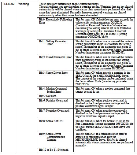
140 File: MP2000_IndividualFunctionDocument_RevC 140/168
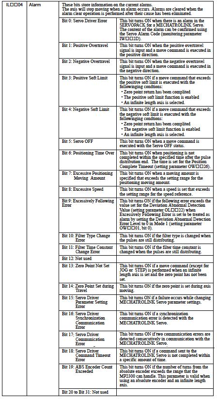
141 File: MP2000_IndividualFunctionDocument_RevC 141/168

142 READ RDA PARAMETER function Function block for MP2000 series <RDPARAM> Function Block Summary This function block reads the parameters of the RDA. The output is always a long even if the parameter is a word or a bit. For bits the value will be a 1 for true and a 0 for false. The parameter input value is the RDA number from the PLC Open Specification. Function Block Diagram <RDPARAM> Function Block Operation Notes To use the function block, the EXECUTE bit must be True, and AXIS and PARAMETER will be constantly read. The block will continue to monitor the RDA for Values as long as the EXECUTE input stays True. If the EXECUTE bit goes low the outputs will be set to zero. Even though the VALUE output is a long it will also represent the bits and words. Six words are used as working registers for this function, starting at the address in Data06W. File: MP2000_IndividualFunctionDocument_RevC 142/168
143 <RDPARAM> Input and Output Register Map Output Registers The following registers are used as outputs from the function block. They can be monitored by the LadderWorks program to check the execution of the function. Output Type Description DONE Bit This bit is ON when the function block has a valid value from the RDA. ERROR Bit If an error occurs during block execution, this output bit Latches ON If the error condition is cleared, this output is reset. VALUE Long The value from the RDA. For bit conditions 1 = TRUE 0 = FALSE Input Registers The following registers are used as inputs to the function block. They select the options and define the parameters that the user needs to make the function work as necessary. Input Type Description Range and state EXECUTE Bit Block enable Block cannot execute unless this is TRUE. Rising edge initiates block TRUE Block enable FALSE Block disable, set all outputs to zero and off AXIS Word Axis number related to the 1~16 PARAMET R block. Word RDA parameter number. The number is specified by the PLCOpen and Yaskawa specification. DATA06W Address Address of the first working register. Six words of register space are used by this function. File: MP2000_IndividualFunctionDocument_RevC 143/168
144 <RDPARAM> Block Fault Condition: The following table outlines several situations that may cause an error, and will turn on the blocks Error output bit. The block Error output will cleared if the EXECUTE bit goes low. axisinerr AB00014A error AB Fault Bit Cause Note The axis number entered on the input is not an acceptable value Parameter specified is not a valid RDA number The function blocks can only control 1 to 16 axes. Any value greater or smaller then this will cause an error. This does not set the RDA Error ID. The number specified must be either the Yaskawa specified RDA area or the PLCOpen specified area. This block can not monitor Master/Slave data. Sets RDA Error ID (MW3**81) bit 3 on if error state exists. <RDPARAM> Working Register This table outlines the data in the six registers used by the function block. There is not usually any need for the user to access any of these bits directly. Register No. Type Name Description AW00000 Working Reserved Reserved AW00001 Working Reserved Reserved AW00002 Working istore Reserved AW00003 Working ivalue Reserved AW00004 Working rdamult Value for address offset to locate proper RDA AW00005 Working Revision Revision Level of the function block. File: MP2000_IndividualFunctionDocument_RevC 144/168
145 <RDPARAM> Parameter List The following tables show the accessible parameters by RDPARAM. # 001-#999 are PLC Open specification and above # 1000 are Yasukawa specification. RDA# Data name Details 005 Movement Type 0: Rotary 1: Liner 006 Position Period Length of Period for rotational systems. [count] 007 Set Position Commanded position. [count] 008 Act Position Actual position. [count] 009 Max Velocity Maximum velocity. [count/sec] 010 Set Velocity Commanded velocity. [count/sec] 011 Act Velocity Actual Velocity of axes. [count/sec] 012 Set Acceleration Commanded acceleration. [count/sec 2 ] 013 Act Acceleration Actual acceleration. [count/sec 2 ] 014 Max Acceleration Maximum acceleration. [count/sec 2 ] 015 Set Deceleration Commanded deceleration. [count/sec 2 ] 016 Act Deceleration Actual deceleration. [count/sec 2 ] 017 Max Deceleration Maximum deceleration. [count/sec 2 ] 018 Set S-Curve Filter Commanded S-Curve Filter [ms] (S curve time) 019 Act S-Curve Filter Actual S-Curve Filter [ms] (S curve time) 020 Max S-Curve Filter Maximum S-Curve filter [ms] (S curve time) 021 Act Torque Actual Torque [0.01% of rated torque] 027 HW Limit Enable Enable / disable hardware end switch (to be used after 028 Capt Position Capture position [count] 029 Capture Occurred Capture signal occurred (reset with writing) 030 Ramp Shape Shape of Acc/Dec profile. 0 = Trapezoid; 1= S-Shape; rest supplier dependent 031 Axis State State of the Axis 0: reserved for power off situation 1:ErrorStopped Motion 2: Stopped Motion 3: Standstill 4: Discrete motion 5: Continuous motion File: MP2000_IndividualFunctionDocument_RevC 145/168
146 1000 Clear Pending Action 1001 Abort Stop axis discontinuous motion (RDA#031) 1002 Command Bit One Scan Pulse of Motion Block Execution 1003 Accelerating The motion is in acceleration Decelerating The motion is in deceleration Steady? 1006 Ext Pos. Captured Registration occurred 1033 Motor Rated Speed Rated speed of servo motor [rpm] 1034 Encoder Resolution Servo motor PG post-quad resolution value [pulse/rev] resolution ( d t ) 1035 Factor FF Feed Forward gain (1000=100%) bit0: Servo ON, bit1: Positive Enabled, bit2: Negative Enabled 1036 Enable Type 1037 Move State The last motion commanded; 0:Stop, 1:MOVVEL, 2:MOVINC, 3:MOVABS, 4:MOVADDTV, 5:HOME, 6:LTCHTGT, 7:GEAR, 8:CAM 1038 Block Running The last executed Function block Number STATUS Bit0:Running, Bit1:Error, bit2:interruption bit0: No Home Switch, bit1: Over travel, bit2: Time-out, bit3: Value to Great, bit4: Direction Not Allowed, bit5: Position error, bit6: No 1040 Error ID 1 Motor Power, bit7: Servo alarm bit8: Spare, bit9: Track Fail, bita: RDA error, bitb: Error stop, bitc: Table error, bitd: Servo off 1041 Error ID 2 Spare 1043 Ext Pos. Captured Registered position [count] 1044 Module number Module No 1045 Axis number Axis No File: MP2000_IndividualFunctionDocument_RevC 146/168
147 1060 CAM type OFF: Return, ON: One way 1061 Positive Cycle End 1062 Negative Cycle End 1092 CAM state On when CAM Master position, includes CAM-Shift, rolled over in positive direction. On when CAM Master position, includes CAM-Shift, rolled over in Negative direction. State of CAMing. bit0: Disengaged, bit1:waiting to Engage, bit2:caming is locked, bit3:waiting to disengage 1093 TABLE size Cam Table Size 1094 CAM shift Absolute CAM Shift amount [count] 1095 SLAVE offset Absolute Offset amount [count] 1096 CAM scale Absolute Acale amount [0.01%] 1097 Machine Cycle Machine Cycle [count] 1098 Data Counter Raw master data for master-slave pair [count] 1099 Mod Data Modulated master data for master/slave pair. [count] State of Gearing. bit0:disengaged, bit1:accelerating, 1105 GEAR state bit2:gearing is locked and synched, bit3:decelerating File: MP2000_IndividualFunctionDocument_RevC 147/168

148 WRITE RDA PARAMETER function Function block for MP2000 series <WRTPARAM> Function Block Summary This function block writes values to the RDA parameter. The value set is always a long even if the parameter calls to a bit. In case of bit information, ON=1 and OFF=0. The input value of PARAMETR is RDA number of the PLC Open specification. Function Block Diagram <WRTPARAM> Function Block operation Notes To use the function block, the EXECUTE bit must be True. The block will write the value to the parameter in the RDA only on the rising edge of the Execute input and if there is no errors reported in the block. If the EXECUTE bit goes low the outputs will be set to zero. To set a bit in the RDA, enter the value of a one in the VALUESET input and execute block. A zero in the VALUESET input will reset the bit. Even though this block may write to a parameter care must be taken that the parameter not be one that is controlled by another block. (ie. Actual position is written to by the SVON block. Any changes to this value will cause the value to be over written by the SVON block the very next scan. Six words are used as working registers for this function, starting at the address in Data06W. File: MP2000_IndividualFunctionDocument_RevC 148/168
149 <WRTPARAM> Input and Output Register Map Output Registers The following registers are used as outputs from the function block. They can be monitored by the LadderWorks program to check the execution of the function. Output Type Description DONE Bit When the value has been successfully stored and the execute input is high, this bit will go high ERROR Bit If an error occurs during block execution, this output bit Latches ON. Input Registers The following registers are used as inputs to the function block. They select the options and define the parameters that the user needs to make the function work as necessary. Input Type Description Range and state EXECUTE Bit Block enable Block cannot execute unless this is TRUE. Rising edge initiates block TRUE Block enable FALSE Block disable, set all outputs to zero and off AXIS Word Axis number related to the 1~16 PARAMET R VALUESE T block Word RDA parameter number It must be RDA number of the PLC Open or Yasukawa specification Long Value to be stored in the RDA DATA06W Address Address of the first working register. Since a long is used for all RDA parameters an Error will occur if the value is to great for the word or bit that is being set. For bit, ON=1 and OFF=0. Six words of register space are used by this function. File: MP2000_IndividualFunctionDocument_RevC 149/168
150 <WRTPARAM> Block Fault Condition: The following table outlines several situations that may cause an error. The block error can be cleared by the EXECUTE bit going low axisinerr AB00000F Notspec AB00000E valueout AB00000D Fault Bit Cause Note The axis number entered on the input is not an acceptable value Parameter specified is not a valid RDA number Value out of range for the RDA The function blocks can only control 1 to 16axis. Any value greater or smaller then this will cause an error. This does not set the RDA Error ID. The number specified must be either the Yaskawa specified RDA area or the PLCOpen specified area. This block can not monitor Master/Slave data. Sets RDA Error ID (MW3**81) bit 3 on if error state exists. Value must be within range of value being stored or error will occur. Sets RDA Error ID (MW3**81) bit 3 on if error state exists. <WRTPARAM> Working Registers This table outlines the data in the six registers used by the function block. There is not usually any need for the user to access any of these bits directly. Register No TYPE Name Content AW00000 Working Reserved Reserved AW00001 Working Reserved Reserved AW00002 Working istore Reserved AW00003 Working ivalue Reserved AW00004 Working rdamult Value for address offset to locate proper RDA AW00005 Working Revision Revision Level of the function block. File: MP2000_IndividualFunctionDocument_RevC 150/168
151 <WRTPARAM> Parameter list The following table shows the accessible parameters by RDPARAM. #001 through #999 are PLCOpen specification and above #1000 are supplier specific.. RDA# Data name Details 005 Movement Type 0: Rotor 1: Liner 006 Position Period Length of Period for rotational systems. [count] 007 Set Position Commanded position. [count] 008 Act Position Actual position. [count] 009 Max Velocity Maximum velocity. [count/sec] 010 Set Velocity Commanded velocity. [count/sec] 011 Act Velocity Actual Velocity of axes. [count/sec] 012 Set Acceleration Commanded acceleration. [count/sec 2 ] 013 Act Acceleration Actual acceleration. [count/sec 2 ] 014 Max Acceleration Maximum acceleration. [count/sec 2 ] 015 Set Deceleration Commanded deceleration. [count/sec 2 ] 016 Act Deceleration Actual deceleration. [count/sec 2 ] 017 Max Deceleration Maximum deceleration. [count/sec 2 ] 018 Set S-Curve Filter Commanded S-Curve Filter [ms] (S curve time) 019 Act S-Curve Filter Actual S-Curve Filter [ms] (S curve time) 020 Max S-Curve Filter Maximum S-Curve filter [ms] (S curve time) 021 Act Torque Actual Torque [0.01% of rated torque] 027 HW Limit Enable Enable / disable hardware end switch (to be used after 028 Capt Position Capture position [count] 029 Capture Occurred Capture signal occurred (reset with writing) 030 Ramp Shape Shape of Acc/Dec profile. 0 = Trapezoid; 1= S-Shape; rest supplier dependent 031 Axis State State of the Axis 0: reserved for power off situation 1:ErrorStopped Motion 2: Stopped Motion 3: Standstill 4: Discrete motion 5: Continuous motion File: MP2000_IndividualFunctionDocument_RevC 151/168
152 1000 Clear Pending Action 1001 Abort Stop axis discontinuous motion (RDA#031) 1002 Command Bit One Scan Pulse of Motion Block Execution 1003 Accelerating The motion is in acceleration Decelerating The motion is in deceleration Steady? 1006 Ext Pos. Captured Registration occurred 1033 Motor Rated Speed Rated speed of servo motor [rpm] 1034 Encoder Resolution Servo motor PG post-quad resolution value [pulse/rev] resolution 1035 Factor FF ( Feed dforward t ) gain (1000=100%) 1036 Enable Type bit0: Servo ON, bit1: Positive Enabled, bit2: Negative Enabled 1037 Move State The last motion commanded; 0:Stop, 1:MOVVEL, 2:MOVINC, 3:MOVABS, 4:MOVADDTV, 5:HOME, 6:LTCHTGT, 7:GEAR, 8:CAM 1038 Block Running The last executed Function block Number STATUS Bit0:Running, Bit1:Error, bit2:interruption bit0: No Home Switch, bit1: Over travel, bit2: Time-out, bit3: Value to Great, bit4: Direction Not Allowed, bit5: Position error, bit6: No Motor Power, bit7: Servo alarm bit8: Spare, bit9: Track Fail, bita: RDA 1040 Error ID 1 error, bitb: Error stop, bitc: Table error, bitd: Servo off 1041 Error ID 2 Spare 1043 Ext Pos. Captured Registered position [count] 1044 Module number Module No 1045 Axis number Axis No File: MP2000_IndividualFunctionDocument_RevC 152/168
153 1060 CAM type OFF: Return, ON: One way 1061 Positive Cycle End On when CAM Master position, includes CAM-Shift, rolled over in positive direction. On when CAM Master position, includes CAM-Shift, rolled over 1062 Negative Cycle End in Negative direction. State of CAMing. bit0: Disengaged, bit1:waiting to Engage, 1092 CAM state bit2:caming is locked, bit3:waiting to disengage 1093 TABLE size Cam Table Size 1094 CAM shift Absolute CAM Shift amount [count] 1095 SLAVE offset Absolute Offset amount [count] 1096 CAM scale Absolute Acale amount [0.01%] 1097 Machine Cycle Machine Cycle [count] 1098 Data Counter Raw master data for master-slave pair [count] 1099 Mod Data Modulated master data for master/slave pair. [count] State of Gearing. bit0:disengaged, bit1:accelerating, 1105 GEAR state bit2:gearing is locked and synched, bit3:decelerating File: MP2000_IndividualFunctionDocument_RevC 153/168
154 ASCII CHARACTER INPUT Function Block Function block for MP2000 series <ASCIIIN> Function Block Summary This function block receives a sequence of 7-bit or 8-bit ASCII characters of a specified size through the controllers serial port, RS232 or RS422/485 from a transmitter device. This sequence of characters is then stored in table format at an offset global MW register location. Function Block Diagram <ASCIIIN> Function Block Operation Notes To use the function block, the EXECUTE bit must be held ON. If the EXECUTE bit goes off during operation, the block will stop receiving data. On the rising edge of the EXECUTE input, the following two are executed. The EXECUTE input should be maintained ON while in operation. o The set value of START and SIZE are read. o The storage table is initialized by data H2020(Null). ERROR ID output has been added to better troubleshoot communication problems. A zero in the value means no errors or block disabled. Protocol settings must be configured in controller module setup and transmitter setup, and must match (baud rate, parity, stop bit, # data bits). This ASCIIin function block uses a MSG-RCV an embedded function. Since the transmission protocol is set to none (internal setting =3(no procedure 2)(The data of each byte is transferred according to a no procedure)), the Master/Slave setting in module configuration is not necessary. File: MP2000_IndividualFunctionDocument_RevC 154/168
155 This function expects the characters to be received from the source in a continuous stream (Note: if testing is performed by typing in one character at a time from a keyboard, the data reception MSG-RCV will time-out, and only the first character will be received, and the DONE signal will come on). Thirty words are used as working registers for this function, starting at the address in Data30W <ASCIIIN> Input and Output Register Map Output Registers The following registers are used as outputs from the function block. They can be monitored by the LadderWorks program to check the execution of the function. OUTPUT TYPE Content BUSY Bit High while block is receiving data and there are no errors. DONE Bit Goes high when receiving is completed and remains high until execute is turned off. ERROR Bit Goes high if any error occurs in block or on the axis ERROR-ID Word Displays the value of the error in block. NUMCHRIN Word Displays the number of characters received. Input Registers The following registers are used as inputs to the function block. They select the options and define the parameters that the user needs to make the function work as necessary. INPUT TYPE Content Range of State EXECUTE Block enable Block cannot execute unless this is TRUE. TRUE Block enable FALSE Block disable START Word Starting address to store ASCII set. This is fed directly into Param12 of MSG-RCV function. This is the address for an M- register type SIZE Word Maximum number of ASCII characters to be received. Start + Size is fed directly into Param13 of MSG-RCV function (unused M register area) and and higher have been reserved by the RDA parameter. 0~28767 CIR Word Which port is to transmitted from For 217IF-01 1=Port 1 (RS-232C) 2=Port 2 (RS-422/485) DATA30W Address Address of the first working register. Thirty words of register space are used by this function. File: MP2000_IndividualFunctionDocument_RevC 155/168
156 <ASCIIIN> Block Fault Conditions: The following table outlines several situations that may cause an error. The block error can be cleared by the EXECUTE bit going low. Internal Fault Bit Cause Note MSG-RCV has an error. rcverror AB00001F The MSG-RCV internal function has an error. Refer to ERROR-ID output for value. 81= Function code error 82= Address set error 83= Data size error 84= Line number setting error 85= Channel number error 86= Station Address error 88= Transmission unit error 89= Device selection error <ASCIIIN> Working Registers This table outlines the data in the Thirty registers used by the function block. There is not usually any need for the user to access any of these bits directly. The MSG-RCV type registers can be further understood by referencing the MSG-RCV function block in the on line help. Register No. Type Name Description AW00000 Bit 0 IN execute EXECUTE input (XB000000) Bit 7 OUT running Directly controls YB (RUNNING Output) Bit 8 OUT done Directly controls YB (COMPLETE Output) Bit 9 OUT error Directly controls YB (ERROR Output) Bit A Working oneshota Reserved Bit B Working firstpass One shot on rising edge of EXECUTE input to initialize axis. AW00001 MSG-RCV Reserved Reserved AW00002 MSG-RCV Reserved Reserved AW00003 MSG-RCV slave Called station # (Param2) AW00004 MSG-RCV Reserved Reserved AW00005 MSG-RCV Reserved Reserved AW00006 MSG-RCV startadd Data address (Param05) AW00007 MSG-RCV size Data size (Param06) AW00008 MSG-RCV called_cpu Called CPU# (Param7) AW00009 MSG-RCV Reserved Reserved File: MP2000_IndividualFunctionDocument_RevC 156/168
157 AW00010 MSG-RCV Reserved Reserved AW00011 MSG-RCV Reserved Reserved AW00012 MSG-RCV holding_offset AW00013 MSG-RCV staraddress AW00014 MSG-RCV endadd AW00015 MSG-RCV system Reserved AW00016 MSG-RCV Reserved Reserved AW00017 MSG-RCV Reserved Reserved Value to shift data in register (Param11, this is meaningless for non-protocol mode) First address of M register to store data (This sets Param12) End address of M register to store data (this sets param13) AW00018 Working Reserved Reserved AW00019 Working Reserved Reserved AW00020 OUT errorid Directly controls ERROR-ID output (YW00001) AW00021 Working istore Reserved AW00022 Working step Reserved AW00023 Working endaddress Final M register to store data AW00024 Working Reserved Reserved AW00025 Working Reserved Reserved AW00026 Working filterlow Reserved AW00027 Working filterhigh Reserved AW00028 OUT chrcount Number of Characters received Directly controls ERROR-ID output (YW00001). AW00029 Working Revision Revision Level of the function block. File: MP2000_IndividualFunctionDocument_RevC 157/168
158 <ASCIIIN> Example of application: The following examples illustrates how to receive ASCII characters from PC COM1 to Port#1 of the MP IF-01 module (In the First Slot) via RS-232C. MotionWorks is used to monitor the received Character data in registers MW04032 through MW04039 (16 characters). Hyper-terminal tm is used to send the character string in a Text file. Hardware setup Yaskawa W cable connects PC COM2 and MP IF-01 module (the second slot) Port#1 for MotionWorks. PC COM1 and MP IF-01 module (The first slot) Port#1 is connected for ASCII communication. Refer to the user's manual for the pin assignment. The first Slot Port1- PC COM1 Cable for ASCII communication The second slot Port1- PC COM2 Cable for MPE720 communication W MP2300 MotionWorks Software Module Setup Set the MP IF-01 module Port#1 (The first slot) serial interface for ASCII communication. Note that Transmission protocol is set to None. Master/Slave and Serial I/F settings are not used so they will be ignored. Protocol settings are as follows: Transmission protocol: No procedure Transmission mode: None Data length: 8bit Parity bit: Even Stop bit: 1 Stop Baud rate: 9600bps File: MP2000_IndividualFunctionDocument_RevC 158/168
 Baud rate:9600bps Data length:8bit Parity bit:even number Stop bit:1 Stop Flow control:hardware Setup of ASCII-IN function The ASCII-IN function block is inserted in the Low")
159 Hyper-Terminal Serial Port (PC COM1) Setup Setting the serial interface on the PC COM1 for ASCII communication is as follows. (Hyper-Terminal is used) Baud rate:9600bps Data length:8bit Parity bit:even number Stop bit:1 Stop Flow control:hardware Setup of ASCII-IN function The ASCII-IN function block is inserted in the Low Speed drawing L01, called from L using the LadderWorks editor (see block on right). It is important to also note that the function block uses 30 words of local registers, care must be taken not to overwrite those registers. In this example, local I/O is used to control the function block execution. Note that the START input is set to With the SIZE input set to 16, the Character table source is then setup from MW04032 through MW04039 (8 16-bit words holds 16 ASCII characters), The CIR input is set to 1 to indicate Port#1 will be used to receive ASCII characters from the PC Htperterminal. Also MW30000 and higher are reserved for function block operation (RDA). Avoid using RDA area for ASCII character table. Making of ASCII file (TEXT file) The character string can be created in a Text file like Notepad. Test of program operation Execution of the function block is started by switching on input bit IB Then send the Text file with the HyperTerminal. The received characters are seen in the Register List. File: MP2000_IndividualFunctionDocument_RevC 159/168
160 ASCII CHARACTER OUTPUT function Function block for MP2000 series <ASCIIOUT> Function Block Summary This function block sends a sequence of 7-bit or 8-bit ASCII characters of a specified size through the controllers serial port, RS232 or RS422/485 to a receiver device. This sequence of characters is stored in table format at an offset global MW register location. A carriage return (CR) and line feed (LF) can be added to the end of the table if needed. Function Block Diagram <ASCIIOUT> Function Block Operation Notes Character transmission starts at positive edge of EXECUTE input. To use the function block, the EXECUTE input must be held ON. If a carriage return (CR) and line feed (LF) are needed on the end of the table the CRLF bit must be set high. Note that this will insert the Carriage Return and Line Feed (which takes up 8 bits each) at the end of the table. The last 16 bit word data-point in the table will be over written with this before it is sent out the serial port. In this case SIZE indicates the total size of the data to be transmitted, including CrLf. ERROR ID output has been added to better troubleshoot communication problems. A zero in the value means no errors or block disabled. Protocol settings must be configured in controller module setup and receiver setup, and must match (baud rate, parity, stop bit, # data bits). This ASCIIout function block uses a MSG-SEND an embedded function. Since the transmission protocol is set to none (version 3, unit is by byte), the Master/Slave setting in module configuration is not necessary. Twenty-three words are used as working registers for this function, starting at the address in Data23W. File: MP2000_IndividualFunctionDocument_RevC 160/168
161 <ASCIIOUT> Input and Output Register Map Output Registers The following registers are used as outputs from the function block. They can be monitored by the LadderWorks program to check the execution of the function. Output Type Description BUSY Bit High while block is transmitting data and there are no errors. DONE Bit Goes high when transmission is completed and remains high until execute is turned off. ERROR Bit Goes high if any error occurs in block or on the axis ERROR-ID Word Displays the value of the error in block. Input Registers The following registers are used as inputs to the function block. They select the options and define the parameters that the user needs to make the function work as necessary. Input Type Description Range of State EXECUTE Bit Block enable Block cannot execute unless this is TRUE. Pos Edge Block execute TRUE Block enable FALSE Block disable CRLF Bit Inserts a Carriage return and line feed to the end of the table (takes up one 16-bit word, table size remains the same (note this will overwrite the last word of the table with the CrLf). START Word Starting address of ASCII set. This is directly written to Param5 of MSG-SND function. It will represent the address of an M- register type. SIZE Word Number of ASCII characters to be sent (number of bites), also indicates table size This is directly written to Param6 of MSG-SND function CIR Word Indicates the circuit number or port number to send the characters SLAVE Word Destination Station Number This value is set in PARAM02 of the MSG-SND function. DATA23W Address Address of the first working register. TRUE CR and LF are added FALSE no addition (unused M register area) and higher have been reserved by the RDA parameter. 0~28767 For 217IF-01 1=Port 1 (RS-232C) 2=Port 2 (RS-422/485) 1~256 Twenty-three words of register space are used by this function. File: MP2000_IndividualFunctionDocument_RevC 161/168
162 <ASCIIOUT> Block Fault Conditions: The following table outlines several situations that may cause an error, and will turn on the blocks Error output bit. The block Error output will OFF if the EXECUTE bit goes low. Internal Fault Bit Cause Note Improper cir number. Out of range. inrng1 AB inrng2 AB snderr AB00001F Improper slave address MSG-SND has an error. On the initial pass of the block the bit must be high or an error will occur. Sets RDA Error ID (MW3**81) bit 3 on if error state exists. On the initial pass of the block the bit must be high or an error will occur. Sets RDA Error ID (MW3**81) bit 3 on if error state exists. The MSG-SND internal function has an error. Refer to ERROR-ID output for value. 81= function code error 82= address set error 83= data size error 84= line number set error 85= channel number set error 86= station address error 88= transmission part error 89= device selection error <ASCIIOUT> Working Register This table outlines the data in the Twenty-three registers used by the function block. There is not usually any need for the user to access any of these bits directly. The MSG-SND type registers can be further understood by referencing the MSG-SND function block in the on line help. Register No Type Name Description AW00000 Bit 0 IN execute EXECUTE input (XB000000) Bit 1 Working crlf If True, a carriage return and Line feed are inserted at the end of the table. Bit 2 Working oddnum Reserved Bit 3 OUT inrng1 Verifies that CIR-NUM input (XW00003) is in range Bit 4 OUT inrng2 Verifies that SLAVE input (XW00004) is in range Bit 7 OUT running Directly controls YB (RUNNING Output) Bit 8 OUT done Directly controls YB (COMPLETE Output) Bit 9 OUT error Directly controls YB (ERROR Output) Bit A Working oneshota Reserved Bit B Working firstpass One shot on rising edge of EXECUTE input to initialize RDA & sets parameters in the message send function File: MP2000_IndividualFunctionDocument_RevC 162/168
163 AW00001 MSG-SND Reserved Reserved AW00002 MSG-SND Reserved Reserved AW00003 MSG-SND slave Called station # (Param2) AW00004 MSG-SND Reserved Reserved AW00005 MSG-SND Reserved Reserved AW00006 MSG-SND startadd Data address, starting address of data to be sent out (Param5) Data size, number of characters to be sent out AW00007 MSG-SND size (Param6) AW00008 MSG-SND called_cpu Called CPU# (Param7) AW00009 MSG-SND Reserved Reserved AW00010 MSG-SND Reserved Reserved AW00011 MSG-SND Reserved Reserved AW00012 MSG-SND holding_offset Holding register offset (Param11) AW00013 MSG-SND sys_send For system (Param12) AW00014 MSG-SND Reserved Reserved AW00015 MSG-SND Reserved Reserved AW00016 MSG-SND Reserved Reserved AW00017 MSG-SND Reserved Reserved AW00018 Working Reserved Reserved AW00019 Working Reserved Reserved AW00020 OUT errorid Directly controls ERROR-ID output (YW00001) AW00021 Working mod Reserved AW00022 Working Revision Revision Level of the function block. File: MP2000_IndividualFunctionDocument_RevC 163/168
164 <ASCIIOUT> Application Example: The following example illustrates how to send characters from Port #1 of an MP IF-01 module (in the first slot) to COM1 of a PC via RS232. MotionWorks is used to set the Character table data in registers MW04000 through MW04007 (16 characters). Hyperterminal tm is used to receive and display the character string. Hardware setup Yaskawa W cable is connected from Port#1 of the MP IF-01 module (the second slot) to PC COM2 for MotionWorks interface software. Port#1 of the MP IF-01 module (the first slot) and PC COM1 are connected for ASCII communication (refer to the user's manual for wiring). The first slot Port1-PC COM1 Cable for ASCII communication The second slot Port1-PC COM2 Cable for MPE720 communication W MP2300 MotionWorks Software Module setup Setting the serial interface of MP IF-01 module Port#1 (the first slot) for ASCII communication is as follows. Note that Transmission protocol is set to None. Master/Slave and Serial I/F settings are not used so they will be ignored. Protocol settings are as follows: Transmission protocol: No procedure Transmission mode: None Data length: 8bit Parity bit: Even Stop bit: 1 Stop Baud rate: 9600bps File: MP2000_IndividualFunctionDocument_RevC 164/168 Doc Number: eng.mcd
 Port#1 settings Baud rate:9600bps Data length:8bit Parity bit:even number Stop bit:1 Stop Flow")
165 Hyper-Terminal Serial Port Setup A terminal session was opened up called test. The serial port configuration for Com1 is set up identical to the MP IF-01 (the first slot) Port#1 settings Baud rate:9600bps Data length:8bit Parity bit:even number Stop bit:1 Stop Flow control:hardware MotionWorks Application Software Setup The ASCIIOUT function block is inserted in the LOW Speed drawing L01, called from L using the LadderWorks editor (see block on right). It is important to also note that the function block uses 23 words of local registers, care must be taken not to overwrite those registers. In this example, local I/O is used to control the function block execution, CR/LF select. With setting "START" as 4000 and SIZE as 16, the character table source is then setup from MW04000 to MW04007 (ASCII character 16 characters are stored in the register of eight words) If CR/LF is used, then two more characters will be inserted at the end of the table, decreasing the user character table size to MW4000 to MW4006 (7-16-bit words holds 14 ASCII characters). The CIR input is set to 1 to indicate Port#1 of the module will be used to send ASCII characters to the PC Hyper-Terminal. MW30000 and higher are RDA parameter. Avoid using RDA for ASCII character table. File: MP2000_IndividualFunctionDocument_RevC 165/168 Doc Number: eng.mcd


166 Character Table Setup The character table is can be set up easily through the quick reference window. In this case 16 ASCII characters are typed in at MW04000 as This is a test!. The HEX representation can be viewed by register list tool, as shown. Note that each character takes up 8 bits which is two HEX digits. Each 16 bit word can hold two characters. Application Test Run: Execution of the function block is started by switching on input bit IB The HyperTerminal window shows the text output. Note that the data that is sent to the PC and displayed is exactly what is stored in the ASCII character table. General use note: To communicate to any device using ASCII characters, a slave ID and protocol wrapper may need to be developed. This will need to be loaded in the ASCII character register table. File: MP2000_IndividualFunctionDocument_RevC 166/168 Doc Number: eng.mcd
TECHNICAL NOTE MOTION PRODUCT AND ENGINEERING GROUP
 Subject: Product: Engineer: MotionWorks+ Simple Template Program MP-940, MotionWorks+ v2.83 or later Michael J. Miller Who should read this document? Anyone is who is attempting to program an MP-940 Machine
Release Notes for MP2000iec controller firmware
 Release Notes for MP2000iec controller firmware Release 1.2.3 Build 12 Yaskawa America, Inc. October 28, 2010. 1. New Features Number Summary Release Notes 5269 High resolution cpu load information for
MP2000 Quick Reference Guide
 MP2000 Quick Reference Guide Contents Registers 2 Memory Map 3 Register Addressing 4 Global Allocation Map 5 Axis Allocation Overview 6 Axis Allocation Detail 7 Axis Allocation Bit Detail 8 Axis Allocation
Technical Note. NS300/500 Master Ladder Example. NS300 and NS500 Application Modules
 Technical Note NS300/500 Master Ladder Example NS300 and NS500 Application Modules Doc#: Copyright Yaskawa Electric America 2004 May 9, 2007 Page 1 of 16 Summary This document describes the example ladder
Product Demo Instructions. MP2600iec Demo Instructions: v03. Applicable Product: MP2600iec with MotionWorks IEC Pro
 Product Demo Instructions MP2600iec Demo Instructions: v03 Applicable Product: MP2600iec with MotionWorks IEC Pro Yaskawa Electric America 2121 Norman Drive South Waukegan, IL 60085 1-800-927-5292 Page
TECHNICAL NOTE MOTION APPLICATION ENGINEERING GROUP
 Subject: MP2000 Best Practices Guideline Product: MP2000 Controllers Status: Rev 1.1 Summary: This document is a guide for use to implement Best Practices for programming design and architecture for an
Following Statements FOL. Descriptor. These statements are designed to be used with the Model 4000-CFM Option.
 Following Statements These statements are designed to be used with the Model 4000-CFM Option. FOL Name Descriptor Type Defauxlt Syntax Options FOL Following Parameters Set-Up N/A FOL TAB MASTER TAB MDIST
Release Notes for MP2000iec controller firmware
 Release Notes for MP2000iec controller firmware Release 2.0.0 Build 255 Yaskawa America, Inc. May 31,2011 1. New Features Number Summary Release Notes 4919 Function block to read multiple axis parameters
Position-Control Module for MICREX-SX Series
 Position-Control Module for MICREX-SX Series Tadakatsu Aida Michiya Muramoto Yasutaka Tominaga 1. Introduction Generally, in order to operate various machines, various controllers that correspond to a
General. Specifications. F3NC96-0N Positioning Module (with MECHATROLINK-II Interface) GS 34M6H60-02E. General. Specification
 GS 34M6H60-02E. General. Specification") General Specifications GS 34M6H60-02E F3NC96-0N Positioning Module (with MECHATROLINK-II Interface) General This positioning module is to be installed on the base unit of a FA M3 range free controller
General Specifications GS 34M6H60-02E F3NC96-0N Positioning Module (with MECHATROLINK-II Interface) General This positioning module is to be installed on the base unit of a FA M3 range free controller
Drive Technology \ Drive Automation \ System Integration \ Services. MPLCTec.._MX Libraries. Manual. Edition 04/ / EN
 Drive Technology \ Drive Automation \ System Integration \ Services MPLCTec.._MX Libraries Edition 4/8 1663419 / EN Manual SEW-EURODRIVE Driving the world Contents 1 General Notes... 4 1.1 Structure of
Writing a Basic Quickstep Program
 TechNote Writing a Basic Quickstep Program October, 2005 6 Control Technology Corporation, Hopkinton, MA 800.282.5008 www.ctc-control.com Note: This is intended to be used as a supplement to the Quickstep
PLCopen Motion Control Function Block Reference
 PLCopen Motion Control Function Block Reference CONTENTS CHAPTER 1 OVERVIEW 3 1.1 List of FB libraries........................................................................ 3 1.2 FB Status Diagram.......................................................................
AN100 v1.4. EtherCAT network synchronization. Distributed clocks
 AN100 v1.4 EtherCAT network synchronization Many EtherCAT systems benefit greatly from a tight synchronization of devices running on the network. Synchronization is particularly important when drives are
When using the LC-2/20, programming will be more lengthy because data must be transferred using repeated get/put (word) transfer instructions.
 transfer instructions.") Table of ontents The Stepper Motor Positioning Assembly (cat. no. 77-QA) allows programmable control of stepper motors by Allen-Bradley programmable controllers. Data and commands set to the stepper positioning
Table of ontents The Stepper Motor Positioning Assembly (cat. no. 77-QA) allows programmable control of stepper motors by Allen-Bradley programmable controllers. Data and commands set to the stepper positioning
Application Note. Creating PLCopen Compliant Function Blocks in IEC 61131
 1.1.1.1.1.1.1.1.1 Application Note Creating PLCopen Compliant Function Blocks in IEC 61131 Yaskawa America, Inc. Drives & Motion Division 2014 February 23, 2014 Page 1 of 31 Introduction... 3 Benefits...
PLCopen Motion Control Function Block Reference -MR-JE-C
 PLCopen Motion Control Function Block Reference -MR-JE-C CONTENTS CHAPTER 1 OVERVIEW 3 1.1 Introduction............................................................................. 3 1.2 Applicable Hardware
GEMCO. Installation & Programming Manual. Series 1746R. PLC Resolver Interface Module. For Allen-Bradley SLC 500 I/O Chassis
 Series 746R GEMCO PLC Resolver Interface Module Installation & Programming Manual For Allen-Bradley SLC 500 I/O Chassis Spec Tech Industrial 03 Vest Ave. Valley Park, MO 63088 Phone: 888 SPECTECH E-mail:
Product Application Note
 Product Application Note Applicable Product: MPiec Controllers with Rev 1.1 Doc#:TN.MP2000IEC.01 Copyright Yaskawa Electric America 2010 September 18, 2012 Page 1 of 58 1 Application Overview... 4 1.1
EtherCAT Product Family
 EtherCAT Product Family Motion Control Library in C++ Controlling Drives based on CiA 402 or SERCOS device profile 9. August 2016 V2.1 1 Content Introduction to PLCopen and CiA 402 EC-Motion Library Architecture
Release Notes for MPiec controller firmware
 Release Notes for MPiec controller firmware Release 2.1.0 Build 229 Yaskawa America, Inc. January 23, 2012 1. New Features Number Summary Release Notes 5434 MC_Reset should work on axes not discovered
Technical Manual. Linear Flying Shear Application Solution Package. for MPiec Controllers
 Technical Manual Linear Flying Shear Application Solution Package for MPiec Controllers Doc#: TM.MPIEC.02 Copyright Yaskawa America Incorporated 2014 January 20, 2014 Contents Application Overview:...
Manual. Libraries MPLCTec..._MDX, MPLCTecVirtualEncoder for MOVI-PLC. Edition 07/ / EN
 Gearmotors \ Industrial Gear Units \ Drive Electronics \ Drive Automation \ Services Libraries MPLCTec..._MDX, MPLCTecVirtualEncoder for MOVI-PLC Edition 7/27 11494212 / EN Manual SEW-EURODRIVE Driving
Epsilon EP. Compact and Economical. 16 Amp Drive. RoHS approved option! Position Tracker. Epsilon EP.
 Compact and Economical The Series is the most compact digital servo drive in the Control Techniques lineup. Designed to fit in cabinets as small as six inches (152 mm) deep, with cables attached. The drives
EtherCAT User Manual. For SS EtherCAT
 EtherCAT User Manual For SS EtherCAT Table of Contents Introduction to EtherCAT... 3 Commonly Used Acronyms... 3 Protocol... 4 Logical Addressing... 4 Auto Increment Addressing... 4 Fixed Node Addressing...
(Cat. No QA) Product Data
 Product Data") (Cat. No. 1771-QA) Product Data The Stepper Positioning Assembly allows programmable control of stepper motors using Allen-Bradley programmable controllers. Accelerations, decelerations, constant velocities
(Cat. No. 1771-QA) Product Data The Stepper Positioning Assembly allows programmable control of stepper motors using Allen-Bradley programmable controllers. Accelerations, decelerations, constant velocities
Keypad Lay-out. Copyright 2008 Optimal Engineering Systems, Inc
 Keypad Lay-out - 1 - Setting Acceleration Pressing the for each motor. key allows the user to enter the acceleration values 1) Press. 2) The controller displays Select Axis:1 thru 3. 3) Press 1 for X axis,
User manual. Actuator with RS485/SIKONETZ5 interface AG03/1
 User manual Actuator with RS485/SIKONETZ5 interface AG03/1 1 General Information... 4 1.1 DOCUMENTATION... 4 2 Block diagram... 4 3 Display and operating elements... 5 3.1 GENERAL INFORMATION... 5 3.2
Upgrade Information of MPE720 Version 6.07
 Upgrade Information of MPE720 Version 6.07 1 Added and Improved Functions 1.1 Version 6.07 Upgrade Information Items added and features improved from MPE720 version 6.06 to version 6.07 are as follows.
TF5xxx TwinCAT 3 Motion Control
 TF5xxx Motion Control TC3 NC PTP 10 Axes TC3 NC PTP Axes Pack 25 TC3 NC PTP Axes Pack unlimited Technical data TF5000-00pp TF5010-00pp TF5020-00pp TC3 NC PTP 10 Axes implements Motion Control for pointto-point
PLC Programming D R. T A R E K A. T U T U N J I
 PLC Programming D R. T A R E K A. T U T U N J I PLC Programming As PLCs developed and expanded, programming languages have developed with them. The three types of programming languages used in PLCs are:
Orientation F7 Drive Software Technical Manual
 Software Number: VSF11006X, Drive Models: CIMR-F7UXXXXXX-063 Document Number: TM.F7SW.063, Date: 03/03/06, Rev: 06-03 Orientation F7 Drive Software Technical Manual This document is intended to provide
Model 5100/5200 Quick Reference Register Guide
 Model 5100/5200 The information in this document is current as of the following Hardware and Firmware revision levels. Some features may not be supported in earlier revisions. See for the availability
To learn more about using MPI Motion Attributes and MEI Motion Attributes, click here. Error Messages. Validate Motion object
 Motion Objects Motion Objects Introduction A Motion object manages a single axis or group of axes. Its primary function is to provide an interface to command movement on a coordinate system. It also provides
SD17098IX Specifications Networked Stepper Driver & Indexer Revision 0.0
 The SD17098IX is a 170V 9.8amp stepper driver and indexer combination that communicates on a Network. The available networks, along with the corresponding AMCI part numbers, are shown in the following
DMP1040. [Outline of Specifications]
![DMP1040. [Outline of Specifications]](/thumbs/93/112196646.jpg "DMP1040. [Outline of Specifications]") HT26-11001A mycom DMP1040 Super High Speed Pulse Generator LSI 100 pin QFP [Outline of Specifications] 1 mycom, Inc Introduction This Outline of Specifications summerizes various functions of the Pulse
HT26-11001A mycom DMP1040 Super High Speed Pulse Generator LSI 100 pin QFP [Outline of Specifications] 1 mycom, Inc Introduction This Outline of Specifications summerizes various functions of the Pulse
GPD515/G5 Software Option (VSG114701) Part Number: CIMR-G5MXXXXXF-017 (1) (1) ZZZZ refers to the base Model Number
 Part Number: CIMR-G5MXXXXXF-017 (1) (1) ZZZZ refers to the base Model Number") OV Suppression GPD515/G5 Software Option (VSG114701) Part Number: CIMR-G5MXXXXXF-017 (1) A Yaskawa GPD515/G5 inverter with this software can control rotating loads where the motor is overhauled by stored
OV Suppression GPD515/G5 Software Option (VSG114701) Part Number: CIMR-G5MXXXXXF-017 (1) A Yaskawa GPD515/G5 inverter with this software can control rotating loads where the motor is overhauled by stored
APPLICATION NOTE. Title: SigmaLogic Example Code Example Manual. 1. Application Overview. Revision 2 February 21, 2018 Page 1 of 31
 1. Application Overview SigmaLogic is an EtherNet/IP Indexer that was designed to work seamlessly with the CompactLogix and ControlLogix PLCs from Allen Bradley. Yaskawa has created Add-On Instructions
Everything s possible. Modbus Communication. Reference Manual. DigiFlex Performance Servo Drives. MNCMMBRF-02
 Everything s possible. Modbus Communication Reference Manual DigiFlex Performance Servo Drives www.a-m-c.com MNCMMBRF-02 Preface ADVANCED Motion Controls constantly strives to improve all of its products.
PCE-M134 Series PCE-M134 PCE-M134-LD. Programming Manual. Version: V Jul18
 PCE-M134 Series PCE-M134 PCE-M134-LD Programming Manual Version: V1.4 2017Jul18 To properly use the product, read this manual thoroughly is necessary. Part No.: 81-05123GH10-010 1 Revision History Date
PLC Lib: Tc3_MC2_AdvancedHoming
 Manual PLC Lib: Tc3_MC2_AdvancedHoming TwinCAT 3 Version: Date: 1.2 2017-05-03 Table of contents Table of contents 1 Foreword... 5 1.1 Notes on the documentation... 5 1.2 Safety instructions... 6 2 Overview...
SMAC Control Center Training v1.2. The Ability to do Work & Verify it s Accuracy at the Same Time
 SMAC Control Center Training v1.2 Main functions Easy creation of macros Download programs in controller Run macros Download existing configuration in controller Logging and charting Tuning of position
Upgrade Information of MPE720 Version 7.36
 Upgrade Information of MPE720 Version 7.36 1. Added and Improved Functions 1.1 Version 7.36 Upgrade Information Items added and features improved from MPE720 version 7.35 to version 7.36 are as follows.
WMX Parameter Manual
 WMX Parameter Manual Revision 0.9859 2015 Soft Servo Systems, Inc. Warning / Important Notice Warning The product described herein has the potential through misuse, inattention, or lack of understanding
1.Overview of X7083/X7043/X7023
 1.Overview of X7083/X7043/X7023 11 Introduction X7083/X7043/X7023 is an LSI that generates a pulse for controlling the speed and positioning of pulse train inputtype servo motors and stepping motors. X7083
MOTENC Axis PCI Motion & I/O Control Board. Reference Manual Rev 1A, April Copyright 2004 VITAL Systems Inc
 MOTENC-100 8-Axis PCI Motion & I/O Control Board Reference Manual Rev 1A, April-7-2004 Copyright 2004 VITAL Systems Inc www.vitalsystem.com This Page Intentionally Left Blank Table of Contents 1. OVERVIEW...
Upgrade Information of MPE720 Version 7.26
 Upgrade Information of MPE720 Version 7.26 1. Added and Improved Functions 1.1 Ver.7.26Upgrade Information Items added and features improved from MPE720 version 7.24 to version 7.26 are as follows. No.
Mitsubishi Simple Motion Module MELSEC iq-r Series RD77MS16. Sample Screen Manual. Mitsubishi Electric Corporation
 Mitsubishi Simple Motion Module MELSEC iq-r Series RD77MS16 Sample Screen Manual Mitsubishi Electric Corporation Using the Samples The sample screen data and files such as the instruction manual can be
EtherNet/IP with Applied Motion Drives
 EtherNet/IP with Applied Motion Drives EtherNet/IP with Applied Motion Drives Jeff Kordik CTO Applied Motion Products, Inc. 1 92-5 Rev. B Applied Motion Products Contents Overview of EtherNet/IP...3 EtherNet/IP
Mitsubishi Simple Motion Module MELSEC-L Series LD77MS16
 Mitsubishi Simple Motion Module MELSEC-L Series LD77MS16 Sample Screen Manual Mitsubishi Electric Corporation Using the Samples The sample screen data and files such as the instruction manual can be used
Application Note. Rotary Knife Application Solution Package for MPiec Series Controllers
 Application Note Rotary Knife Application Solution Package for MPiec Series Controllers Yaskawa Electric America 2121 Norman Drive South Waukegan, IL 60085 1-800-927-5292 Page 1 of 21 Contents Application
USER GUIDE. Tolomatic Motion Interface (TMI) Actuator Control Solutions for: ACS Stepper Drive/Controller Tolomatic Electric Linear Actuators
 Actuator Control Solutions for: ACS Stepper Drive/Controller Tolomatic Electric Linear Actuators") USER GUIDE Tolomatic Motion Interface (TMI) Actuator Control Solutions for: ACS Stepper Drive/Controller Tolomatic Electric Linear Actuators 3600-4167_01_TMI_Gui LINEAR SOLUTIONS MADE EASY Tolomatic reserves
USER GUIDE Tolomatic Motion Interface (TMI) Actuator Control Solutions for: ACS Stepper Drive/Controller Tolomatic Electric Linear Actuators 3600-4167_01_TMI_Gui LINEAR SOLUTIONS MADE EASY Tolomatic reserves
Manual. TwinCAT MC Flying Saw. TwinCAT 3. Version: Date: Order No.: TF5055
 Manual TwinCAT 3 Version: Date: Order No.: 1.1 2016-06-27 TF5055 Table of contents Table of contents 1 Foreword... 4 1.1 Notes on the documentation... 4 1.2 Safety instructions... 5 2 Overview... 6 3
Mitsubishi Motion Controller CPU MELSEC-Q Series Q173DCPU. Sample Screen Manual. Mitsubishi Electric Corporation
 Mitsubishi Motion Controller CPU MELSEC-Q Series Q173DCPU Sample Screen Manual Mitsubishi Electric Corporation Using the Samples The sample screen data and files such as the instruction manual can be used
NCT. PLC Programmer s Manual. Machine Tool Controls. From SW Version x.061 (M) (L)
 (L)") NCT Machine Tool Controls PLC Programmer s Manual From SW Version x.061 (M) (L) Produced and developed by NCT Automation kft. H1148 Budapest Fogarasi út 7 : Letters: 1631 Bp. P.O. Box 26 F Phone: (+36
NCT Machine Tool Controls PLC Programmer s Manual From SW Version x.061 (M) (L) Produced and developed by NCT Automation kft. H1148 Budapest Fogarasi út 7 : Letters: 1631 Bp. P.O. Box 26 F Phone: (+36
Communication. Outline of Communication. Merits
 Communication Outline of Communication You can connect up to MINAS-A series with your computer or NC via serial communication based on RS and RS, and can execute the following functions. () Change over
TB267 (Rev4) - CNC11 Yaskawa Sigma5 Precision Mode Setup
 - CNC11 Yaskawa Sigma5 Precision Mode Setup") TB267 (Rev4) - CNC11 Yaskawa Sigma5 Precision Mode Setup Overview: This document will walk you through the process of configurating and tuning a Yaskawa Sigma V Servo Drive Pack and motor with a centroid
TB267 (Rev4) - CNC11 Yaskawa Sigma5 Precision Mode Setup Overview: This document will walk you through the process of configurating and tuning a Yaskawa Sigma V Servo Drive Pack and motor with a centroid
Chapter. Getting Started, Basics. and Examples. In This Chapter...
 Getting Started, Basics and Examples Chapter 2 In This Chapter... Overview... 2-2 Basic Motion Functions, Summary of Examples... 2-2 Detailed Example: Configure and Test a Quadrature Input... 2-7 Detailed
Date 18/05/17. Operation and maintenance instructions for driver configurator QSet
 Operation and maintenance instructions 28 1. General recommendations The recommendations regarding safe use in this document should be observed at all times. Some hazards can only be associated with the
Micro800 Programmable Controllers: Getting Started with Motion Control Using a Simulated Axis
 Quick Start Micro800 Programmable Controllers: Getting Started with Motion Control Using a Simulated Axis Catalog Numbers Bulletin 2080-LC30, 2080-LC50 Important User Information Solid-state equipment
MECH 1500 Quiz 4 Review
 Class: Date: MECH 1500 Quiz 4 Review True/False Indicate whether the statement is true or false. 1. For the timer relay contact shown, when the relay coil is energized, there is a time delay before the
Machine Controller MP900/MP2000 Series New Ladder Editor PROGRAMMING MANUAL MANUAL NO. SIEZ-C C
 Machine Controller MP900/MP2000 Series New Ladder Editor PROGRAMMING MANUAL MANUAL NO. SIEZ-C887-13.1C Copyright 2001 YASKAWA ELECTRIC CORPORATION All rights reserved. No part of this publication may be
Appendix C: HVAC PRO Modules
 FANs 637.5, 1637.5 Appendix Section Issue Date 0400 APPLICATION NOTE Appendix C: HVAC PRO Modules HVAC PRO Modules...3 Introduction...*3 Key Concepts...*4 ABS VALUE... 6 ADD... 6 ANALOG OUTPUT... 6 AND...
User Manual. User Program(GUI) Function
 Function") User Manual User Program(GUI) Function - Table of Contents - 1. Installation and Connection of the Program... 4 1.1 Installation Environment of PC... 4 1.2 User Program(GUI) Installation Method... 4 1.3
User Manual User Program(GUI) Function - Table of Contents - 1. Installation and Connection of the Program... 4 1.1 Installation Environment of PC... 4 1.2 User Program(GUI) Installation Method... 4 1.3
Equipment for Machine Tools
 Equipment for Machine Tools WF 725/WF 726 Positioning modules Planning Instructions Part 3 Description of the Interface for the Standard Software I-726, II-726 and III-726 Edition December 1991 This publication
KOLLMORGEN. SERVOSTAR CD. SERCOS IDN Manual M-SS rev. F. Solutions by D A N A H E R M O T I O N
 KOLLMORGEN www.danahermotion.com SERVOSTAR CD Solutions by D A N A H E R M O T I O N SERCOS IDN Manual M-SS-017-05 rev. F Revision History Revision Edition Date Reason for Revision 1 05/01/1999 Initial
Modbus User Manual APPLIED MOTION PRODUCTS, INC. Modbus is a registered trademark of Schneider Electric, licensed to the Modbus Organization, Inc.
 APPLIED MOTION PRODUCTS, INC. Modbus is a registered trademark of Schneider Electric, licensed to the Modbus Organization, Inc. Covers the following Modbus RTU enabled drives: ST5-Q-RN ST5-Q-RE ST5-Q-NN
Application for Drive Technology
 Application for Drive Technology Technology CPU Documentation Technology template MoveCircle 2D Warranty, Liability and Support Note The Application Examples are not binding and do not claim to be complete
Copley Indexer Program User Guide
 Copley Indexer Program User Guide P/N 95-00414-000 Version 1.0 May 2005 Copley Indexer Program User Guide TABLE OF CONTENTS About This Manual... iv Overview and Scope...iv Related Documentation...iv Comments...iv
Tongta Inverter TDS-F8
 Tongta Inverter TDS-F8 MODBUS Communication Application Manual Please ensure the user gets this manual, for the optimal use of this device. 1. Introduction: TEK-DRIVE / TDS-F8 INVERTER MODBUS Communication
USER GUIDE. Tolomatic Motion Interface (TMI) Actuator Control Solutions for: ACS Stepper Drive/Controller Tolomatic Electric Linear Actuators
 Actuator Control Solutions for: ACS Stepper Drive/Controller Tolomatic Electric Linear Actuators") USER GUIDE Tolomatic Motion Interface (TMI) Actuator Control Solutions for: ACS Stepper Drive/Controller Tolomatic Electric Linear Actuators 3600-4167_02_TMI_Gui LINEAR SOLUTIONS MADE EASY Tolomatic reserves
USER GUIDE Tolomatic Motion Interface (TMI) Actuator Control Solutions for: ACS Stepper Drive/Controller Tolomatic Electric Linear Actuators 3600-4167_02_TMI_Gui LINEAR SOLUTIONS MADE EASY Tolomatic reserves
Motor Objects. Methods
 Motor Objects Motor Objects Introduction A Motor object manages a single motor on a controller. It represents the physical connections between the motor, drive, and associated I/O. The Motor object contains
General Description. Galil Controllers
 Command Language Galil s Command Language is comprised of intuitive, two-letter, Englishlike ASCII commands that make programming as quick and easy as possible. For example, the BG command begins motion
STF-EtherCAT User Manual
 STF-EtherCAT User Manual APPLIED MOTION PRODUCTS, INC. 1 Contents Introduction to EtherCAT... 4 Commonly Used Acronyms... 4 Protocol... 5 Logical Addressing...5 Auto Increment Addressing...5 Fixed Node
IPC Machine Controller Industrial Panel PC / Industrial Box PC
 Industrial PC Platform NY-series IPC Machine Controller Industrial Panel PC / Industrial Box PC Motion Control User s Manual NY532-1500 NY532-1400 NY532-1300 NY532-5400 NY512-1500 NY512-1400 NY512-1300
Positioning Controller
 Edition December 2008 Positioning Controller Introduction Application Note "Interpolation Position Mode" Edition December 2008 EPOS2 50/5, EPOS Module 36/2 Firmware version 2101h or higher The EPOS2 positioning
Accurate Synchronization of EtherCAT Systems Using Distributed Clocks
 Accurate Synchronization of EtherCAT Systems Using Distributed Clocks Joseph E Stubbs, PE EtherCAT Technology Group 12/2010 EtherCAT Technology Group (1) Purpose of this presentation Gain a basic understanding
FANUC HMIs IMPORTANT PRODUCT INFORMATION. General Description READ THIS INFORMATION FIRST. High Performance. Easy to Use
 Restarts for autonumbers that do not restart in each chapter. figure bi level 1, reset table_big level 1, reset chap_big level 1, reset app_big level 1, reset figure_ap level 1, reset table_ap level 1,
Using the New Profile Editor
 Using the New Profile Editor Introduction Welcome to the new motion profile editor for Motion Analyzer Online! We ve gathered a lot of feedback from our users and have incorporated it into the latest release.
Operating instructions
 Operating instructions CamEditor for the electronical cam control COMPAX XX70M & S as of CamEditor - version V3.00 as of COMPAX XX70 M /S - software V2.00 November 98 We automate motion C E R T DIN EN
December 9, ExROS -- Excitron Robot Operating System
 ExROS -- Excitron Robot Operating System December 9, 2014 These notes are additional details about ExROS and general operation of our new X Controllers. Our plan is to merge these notes into the X Controller
Basic Control of SMVector over Ethernet IP using RSLogix 5000
 Basic Control of SMVector over Ethernet IP using RSLogix 5000 This application example illustrates the basic control of an SMVector Drive over Ethernet IP using an RSLogix 5000 programmed PLC. A CompactLogix
SERIES SIX PROGRAMMABLE CONTROLLERS AXIS POSITIONING MODULE (TYPE 1) GEK-83543A GENERAL DESCRIPTION
 GEK-83543A GENERAL DESCRIPTION") SERIES SIX GEK-83543A PROGRAMMABLE CONTROLLERS I AXIS POSITIONING MODULE (TYPE 1) GENERAL DESCRIPTION The Axis Positioning Module (APM) is an intelligent, programmable, single-axis positioning controller
SERIES SIX GEK-83543A PROGRAMMABLE CONTROLLERS I AXIS POSITIONING MODULE (TYPE 1) GENERAL DESCRIPTION The Axis Positioning Module (APM) is an intelligent, programmable, single-axis positioning controller
MPiec Web User Interface
 TRAINING MPiec Web User Interface Class No. TRM010-Mpiec-WebUI Rev. A.01 Date: October 31, 2016 2015 YASKAWA America, Inc. YASKAWA.COM Instructor Introduction Matt Pelletier Product Training Engineer training@yaskawa.com
User Guide Advanced Position Controller Position Control for Unidrive SP Part Number: Issue Number: 5
 www.controltechniques.com User Advanced Position Controller Position Control for Unidrive SP Part Number: 471-34-5 Issue Number: 5 General Information The manufacturer accepts no liability for any consequences
MOTENC-Lite 4-Axis PCI Motion & I/O Control Board. Reference Manual Rev 1.1, June 20, Copyright 2005 VITAL Systems Inc
 MOTENC-Lite 4-Axis PCI Motion & I/O Control Board Reference Manual Rev 1.1, June 20, 2005 Copyright 2005 VITAL Systems Inc www.vitalsystem.com This Page Intentionally Left Blank Table of Contents 1. OVERVIEW...
Controllers. Stepping Motors. Stepping Motors A-357. Controllers SCX10 A-364. Introduction AR AS 0.36
 Stepping Motors s / 0.9 Geared AC Input Motor & DC Input Motor & Motor Only Page Page A-364 RK EMP400 Series A-374 A-90 UMK SG8030J Series A-122 A-388 s s A-357 s EMP400 SG8030J Overview of s At Oriental
PowerLogic ION6200 Serial Communications Protocol and ION / Modbus Register Map
 70022-05-XX PROTOCOL DOCUMENT 04/2007 PowerLogic ION6200 Serial Communications Protocol and ION / Modbus Register Map This document explains the Modbus protocol on the ION6200 meter. The ION6200 meter
^1 EZ-QMAC Setup Software
 ^1 EZ-QMAC Setup Software ^3 EZ- QMAC Manual ^4 5EZ-603506-xSxx ^5 January 1, 2003 Single Source Machine Control Power // Flexibility // Ease of Use 21314 Lassen Street Chatsworth, CA 91311 // Tel. (818)
User manual. magnetic absolute positioning drive with AG03
 User manual magnetic absolute positioning drive with interface AG03 1 GENERAL REMARKS...5 1.1 SYMBOLS AND THEIR MEANING...5 1.2 DOCUMENTATION...5 2 FUNCTIONAL DESCRIPTION...6 2.1 SYSTEM STATUS WORD...6
Artisan Technology Group is your source for quality new and certified-used/pre-owned equipment
 Artisan Technology Group is your source for quality new and certified-used/pre-owned equipment FAST SHIPPING AND DELIVERY TENS OF THOUSANDS OF IN-STOCK ITEMS EQUIPMENT DEMOS HUNDREDS OF MANUFACTURERS SUPPORTED
Manual. MOVIAXIS MX Multi-Axis Servo Inverter Virtual Encoder Technology Function. Edition 05/ / EN
 Gearmotors \ Industrial Gear Units \ Drive Electronics \ Drive Automation \ Services MOVIAXIS MX Multi-Axis Servo Inverter Virtual Encoder Technology Function Edition 05/2007 11576626 / EN Manual SEW-EURODRIVE
Programming Manual. Original Instructions. itrak System. Firmware Version: 1.110
 Programming Manual Original Instructions itrak System Firmware Version: 1.11 Important User Information Read this document and the documents listed in the additional resources section about installation,
TC40 - Pre-Instructional Survey
 TC40 - Pre-Instructional Survey 1. Identify the instruction symbol shown. A. Normally Open B. Examine Input Open C. Examine Input Closed D. Normally Closed 2. Identify the instruction symbol shown. A.
User Manual. User Program(GUI) Function. ( Rev )
 Function. ( Rev )") 1 User Manual User Program(GUI) Function ( Rev.08.05.09 ) - Table of Contents - 1. Installation and Connection of the Program... 4 1.1 Installation Environment of PC... 4 1.2 User Program(GUI) Version...
1 User Manual User Program(GUI) Function ( Rev.08.05.09 ) - Table of Contents - 1. Installation and Connection of the Program... 4 1.1 Installation Environment of PC... 4 1.2 User Program(GUI) Version...
+ Lester Control Systems Ltd
 + Lester Control Systems Ltd Unit D, 18 Imperial Way, Croydon, Surrey, CR0 4RR. Tel: 020 8288 0668 Fax: 020 8288 0667 Email: info@lestercontrols.co.uk Web: www.lestercontrols.co.uk TECHNICAL MANUAL FOR
Allen-Bradley. User Manual. Stepper Positioning Assembly. (Cat. No QA)
") Allen-Bradley Stepper Positioning Assembly User Manual (at. No. 77 QA) Important User Information Because of the variety of uses for the products described in this publication, those responsible for the
Allen-Bradley Stepper Positioning Assembly User Manual (at. No. 77 QA) Important User Information Because of the variety of uses for the products described in this publication, those responsible for the
Upgrade Information of MPE720 Version 7.30
 Upgrade Information of MPE720 Version 7.30 1. Added and Improved Functions 1.1 Version 7.30 Upgrade Information Items added and features improved from MPE720 version 7.29 to version 7.30 are as follows.
Rexroth MLC Tech-FB for Packaging Applications
 Electric Drives Linear Motion and Hydraulics Assembly Technologies Pneumatics Service Rexroth MLC Tech-FB for Packaging Applications R911321344 Edition 01 Application Manual Bosch Rexroth AG Electric Drives
1.5 axis motion controller
 Ver. CHARGE POWER CN3 CN CN SERVOPACK RUN RD MCW5 STS SD 6 +4V SGDH- Ver. CHARGE CN CN3 CN SERVOPACK POWER 0 MCW5 RUN STS RD SD 6 +4V R88A-MCW5-@.5 axis motion controller Advanced motion made perfectly