Arduino Mega 2560 Datasheet
|
|
|
- Antonia Carson
- 5 years ago
- Views:
Transcription
1
2
3
4


5 Arduino Mega 2560 Datasheet
, 16 analog inputs, 4 UARTs (hardware serial ports), a 16 MHz crystal oscillator, a USB")

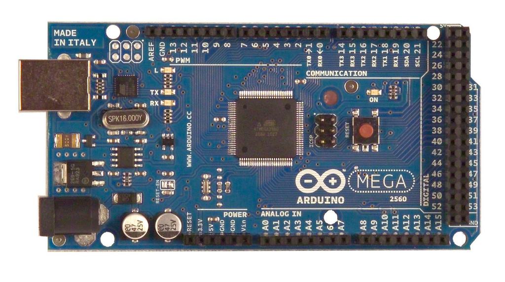
6 Overview The Arduino Mega 2560 is a microcontroller board based on the ATmega2560 (datasheet). It has 54 digital input/output pins (of which 14 can be used as PWM outputs), 16 analog inputs, 4 UARTs (hardware serial ports), a 16 MHz crystal oscillator, a USB connection, a power jack, an ICSP header, and a reset button. It contains everything needed to support the microcontroller; simply connect it to a computer with a USB cable or power it with a AC-to-DC adapter or battery to get started. The Mega is compatible with most shields designed for the Arduino Duemilanove or Diecimila. Schematic & Reference Design EAGLE files: arduino-mega2560-reference-design.zip
7 Schematic: arduino-mega2560-schematic.pdf Summary Microcontroller ATmega2560 Operating Voltage 5V Input Voltage (recommended) 7-12V Input Voltage (limits) 6-20V Digital I/O Pins 54 (of which 14 provide PWM output) Analog Input Pins 16 DC Current per I/O Pin 40 ma DC Current for 3.3V Pin 50 ma Flash Memory 256 KB of which 8 KB used by bootloader SRAM 8 KB EEPROM Clock Speed 4 KB 16 MHz Power The Arduino Mega can be powered via the USB connection or with an external power supply. The power source is selected automatically. External (non-usb) power can come either from an AC-to-DC adapter (wall-wart) or battery. The adapter can be connected by plugging a 2.1mm center-positive plug into the board's power jack. Leads from a battery can be inserted in the Gnd and Vin pin headers of the POWER connector.
8 The board can operate on an external supply of 6 to 20 volts. If supplied with less than 7V, however, the 5V pin may supply less than five volts and the board may be unstable. If using more than 12V, the voltage regulator may overheat and damage the board. The recommended range is 7 to 12 volts. The Mega2560 differs from all preceding boards in that it does not use the FTDI USB-to-serial driver chip. Instead, it features the Atmega8U2 programmed as a USB-to-serial converter.
9 The power pins are as follows: VIN. The input voltage to the Arduino board when it's using an external power source(as opposed to 5 volts from the USB connection or other regulated power source). You can supply voltage through this pin, or, if supplying voltage via the power jack, access it through this pin. 5V. The regulated power supply used to power the microcontroller and othercomponents on the board. This can come either from VIN via an onboard regulator, or be supplied by USB or another regulated 5V supply. 3V3. A 3.3 volt supply generated by the on-board regulator. Maximum current draw is50 ma. GND. Ground pins. Memory The ATmega2560 has 256 KB of flash memory for storing code (of which 8 KB is used for the bootloader), 8 KB of SRAM and 4 KB of EEPROM (which can be read and written with the EEPROM library). Input and Output Each of the 54 digital pins on the Mega can be used as an input or output, using pinmode(), digitalwrite(),anddigitalread() functions.they operate at 5 volts. Each pin can provide orreceive a maximum of 40 ma and has an internal pull-up resistor (disconnected by default) of kohms. In addition, some pins have specialized functions:
10 Serial: 0 (RX) and 1 (TX); Serial 1: 19 (RX) and 18 (TX); Serial 2: 17 (RX) and 16 (TX); Serial 3: 15 (RX) and 14 (TX). Used to receive (RX) and transmit(tx) TTL serial data. Pins 0 and 1 are also connected to the corresponding pins of the ATmega8U2 USB-to-TTL Serial chip. External Interrupts: 2 (interrupt 0), 3 (interrupt 1), 18 (interrupt 5), 19 (interrupt 4), 20 (interrupt 3), and 21 (interrupt 2). These pins can beconfigured to trigger an interrupt on a low value, a rising or falling edge, or a change in value. See the attachinterrupt()function for details. PWM: 0 to 13. Provide 8-bit PWM output with theanalogwrite()function. SPI: 50 (MISO), 51 (MOSI), 52 (SCK), 53 (SS). These pins support SPIcommunication using the SPI library. The SPI pins are also broken out on the ICSP header, which is physically compatible with the Uno, Duemilanove and Diecimila. LED: 13. There is a built-in LED connected to digital pin 13. When the pin is HIGHvalue, the LED is on, when the pin is LOW, it's off.,
11 I2C: 20 (SDA) and 21 (SCL). Support I2C (TWI) communication using thewirelibrary(documentationon the Wiring website). Note that these pins are not in thesame location as the I2C pins on the Duemilanove or Diecimila. The Mega2560 has 16 analog inputs, each of which provide 10 bits of resolution (i.e different values). By default they measure from ground to 5 volts, though is it possible to change the upper end of their range using the AREF pin and analogreference() function. There are a couple of other pins on the board: AREF. Reference voltage for the analog inputs. Used withanalogreference(). Reset. Bring this line LOW to reset the microcontroller. Typically used to add a resetbutton to shields which block the one on the board. Communication The Arduino Mega2560 has a number of facilities for communicating with a computer, another Arduino, or other microcontrollers. The ATmega2560 provides four hardware UARTs for TTL (5V) serial communication. An ATmega8U2 on the board channels one of these over USB and provides a virtual com port to software on the computer (Windows machines will need a.inf file, but OSX and Linux machines will recognize the board as a COM port automatically. The Arduino software includes a serial monitor which allows simple textual data to be sent to and from the board. The RX and TX LEDs on the board will flash when data is being transmitted via the ATmega8U2 chip and USB connection to the computer (but not for serial communication on pins 0 and 1). A SoftwareSerial library allows for serial communication on any of the Mega2560's digital pins. The ATmega2560 also supports I2C (TWI) and SPI communication. The Arduino software includes a Wire library to simplify use of the I2C bus; see the documentation on the Wiringwebsitefordetails. For SPI communication, use thespi library.
12 Programming The Arduino Mega can be programmed with the Arduino software (download). For details, see the referenceand tutorials. The ATmega2560 on the Arduino Mega comes preburned with a bootloaderthat allows you to upload new code to it without the use of an external hardware programmer. It communicates using the original STK500 protocol (reference, C header files). You can also bypass the bootloader and program the microcontroller through the ICSP (In-Circuit Serial Programming) header; see theseinstructions for details.
13 Automatic (Software) Reset Rather then requiring a physical press of the reset button before an upload, the Arduino Mega2560 is designed in a way that allows it to be reset by software running on a connected computer. One of the hardware flow control lines (DTR) of the ATmega8U2 is connected to the reset line of the ATmega2560 via a 100 nanofarad capacitor. When this line is asserted (taken low), the reset line drops long enough to reset the chip. The Arduino software uses this capability to allow you to upload code by simply pressing the upload button in the Arduino environment. This means that the bootloader can have a shorter timeout, as the lowering of DTR can be well-coordinated with the start of the upload. This setup has other implications. When the Mega2560 is connected to either a computer running Mac OS X or Linux, it resets each time a connection is made to it from software (via USB). For the following half-second or so, the bootloader is running on the Mega2560. While it is programmed to ignore malformed data (i.e. anything besides an upload of new code), it will intercept the first few bytes of data sent to the board after a connection is opened. If a sketch running on the board receives one-time configuration or other data when it first starts, make sure that the software with which it communicates waits a second after opening the connection and before sending this data. The Mega2560 contains a trace that can be cut to disable the auto-reset. The pads on either side of the trace can be soldered together to re-enable it. It's labeled "RESET-EN". You may also be able to disable the auto-reset by connecting a 110 ohm resistor from 5V to the reset line; see this forum thread for details. USB Overcurrent Protection The Arduino Mega2560 has a resettable polyfuse that protects your computer's USB ports from shorts and overcurrent. Although most computers provide their own internal protection, the fuse provides an extra layer of protection. If more than 500 ma is applied to the USB port, the fuse will automatically break the connection until the short or overload is removed.
14 Physical Characteristics and Shield Compatibility The maximum length and width of the Mega2560 PCB are 4 and 2.1 inches respectively, with the USB connector and power jack extending beyond the former dimension. Three screw holes allow the board to be attached to a surface or case. Note that the distance between digital pins 7 and 8 is 160 mil (0.16"), not an even multiple of the 100 mil spacing of the other pins. The Mega2560 is designed to be compatible with most shields designed for the Uno, Diecimila or Duemilanove. Digital pins 0 to 13 (and the adjacent AREF and GND pins), analog inputs 0 to 5, the power header, and ICSP header are all in equivalent locations. Further the main UART (serial port) is located on the same pins (0 and 1), as are external interrupts 0 and 1 (pins 2 and 3 respectively). SPI is available through the ICSP header on both the Mega2560 and Duemilanove / Diecimila. Please note that I2C is not located on thesame pins on the Mega (20 and 21) as the Duemilanove / Diecimila (analog inputs 4 and 5)

15 MOTOR BLDC 350W HI TORSI Spesifikasi Electric Tegangan = 48V Power watt = 350W over power watt = > 1000W Amper kerja = 16-18A OverAmper maks = >35A Torsi = 18-25Nm recomended kontroler = 48V 350W 17A full fitur kontroller maksimum kontroler = 48V 1000W 35A full fitur kontroller
 Jumlah ruji = 36 lubang Compatible Rim velg = 20\", 24\", 26\" 700c, dan 17\" ring sepeda motor open size as = 15 cm. panjang as = 18cm diameter motor = 24 cm lebar motor = 7 cm bobot = 6 Kg.")
16 Spesifikasi Model Model socket = skun bulat lonjong (Male), socket O ring. atau by request Socket hall = socket 6 pin isi 5. (Male) Jumlah ruji = 36 lubang Compatible Rim velg = 20", 24", 26" 700c, dan 17" ring sepeda motor open size as = 15 cm. panjang as = 18cm diameter motor = 24 cm lebar motor = 7 cm bobot = 6 Kg. Sistem rem = flaksible (terdapat drat untuk adapter tromol maupun disk brake) Kecepatan = 36V: 35 km/jam, 48V: 45km/jam


17 PERBEDAAN STANDAR DAN HI TORSI


18 DESAIN TERBARU, AGUSTUS 2016 BRAND XS MOTOR.

19 APLIKASI: Sepeda listrik model Dowhill, Becak Listrik, Mobil Wahana listrik, Mobil listrik model Proto / Urban concept. Recomended kontroller: BLDC 350W full fitur, BLDC 350W Sensorless dual mode Stock Tersedia : READY STOCK >10 PCS Harga baru : call CS
20 PROGRAM KURSI RODA ELEKTRIK BERBASIS ARDUINO MEGA 2560 // URTouch_ButtonTest // This program is a quick demo of how create and use buttons. // This program requires the UTFT library. // It is assumed that the display module is connected to an // appropriate shield or that you know how to change the pin // numbers in the setup. #include <UTFT.h> #include <URTouch.h> // Define the orientation of the touch screen. Further // information can be found in the instructions. #define TOUCH_ORIENTATION PORTRAIT // Initialize display // // Set the pins to the correct ones for your development board // // Standard Arduino Uno/2009 Shield : <display model>,19,18,17,16 // Standard Arduino Mega/Due shield : <display model>,38,39,40,41 // CTE TFT LCD/SD Shield for Arduino Due : <display model>,25,26,27,28 // Teensy 3.x TFT Test Board : <display model>,23,22, 3, 4 // ElecHouse TFT LCD/SD Shield for Arduino Due : <display model>,22,23,31,33 // // Remember to change the model parameter to suit your display module! UTFT myglcd(itdb32wc,38,39,40,41); // Initialize touchscreen // // Set the pins to the correct ones for your development board // // Standard Arduino Uno/2009 Shield : 15,10,14, 9, 8 // Standard Arduino Mega/Due shield : 6, 5, 4, 3, 2 // CTE TFT LCD/SD Shield for Arduino Due : 6, 5, 4, 3, 2 // Teensy 3.x TFT Test Board : 26,31,27,28,29 // ElecHouse TFT LCD/SD Shield for Arduino Due : 25,26,27,29,30 // URTouch mytouch( 6, 5, 4, 3, 2); // Declare which fonts we will be using extern uint8_t BigFont[]; extern uint8_t SevenSegNumFont[]; uint32_t cx, cy; uint32_t rx[8], ry[8]; uint32_t clx, crx, cty, cby; float px, py; int dispx, dispy, text_y_center; uint32_t calx, caly, cals; char buf[13]; bool setnewcode_flag = 0; bool setoldcode_flag = 0; bool repeat_flag = 1;
21 bool lock_flag = 0; int x, y, z; String stcode = "12345"; String sttemp = ""; char stcurrent[6] = ""; //array 6 dimensi untuk menyimpan inputan angka bukan password char asterisc[6] = ""; // hidden password dengan bentuk bintang - bintang char asterisc_partial[6] = ""; String stlast = ""; String msgcurrent = "";//pesan blink tulisan ke lcd int stcurrentlen=0; // menghapus memori sementara int thisbyte = 0; // data serial hexa desimal int data_sent = 0; // data yang di kirim int buttonstate = 0; //kondisi awal button adalah 0 int SW_pin = 8; // brake int sensorpin = A0; // select the input pin for the photodioda int sensorvalue = 0; // variable to store the value coming from the sensor const int X_pin = 9; // analog pin connected to X output const int Y_pin = 10; // analog pin connected to Y output int kiri1 = 10; // kecepatan motor int kanan1 = 9; int LR = 11; // rotasi motor int RR = 12; int gigimundur = 18; int power = 13; int nilai; int gigimundurstate = 0; int powerstate = 0; int count=0; int val;// simpan nilai kesalahan int stlastserial; /************************* ** Custom functions ** *************************/ void cleardisplay () //kotak hapus angka inputan myglcd.setcolor(230, 230, 230); //myglcd.fillrect(0, 0, 239, 50); // clear display myglcd.fillrect(30, 230, 285, 190); // clear display untuk kotak besar //fix void clearsmalldisplay () //menghapus angka pwd dan tanda bintang myglcd.setcolor(255, 255, 255); //myglcd.fillcircle(51, 27, 16); myglcd.fillcircle(120, 210, 16); //set lingkaran kecil tempat pwd kiri // FIX //myglcd.fillcircle(188, 27, 16); myglcd.fillcircle(200, 210, 16); //set lingkaran kecil tempat pwd kanan //FIX //myglcd.fillrect(51, 11, 188, 43); // clear small display myglcd.fillrect(120, 225, 200, 195); // clear small display //FIX void drawbuttons() // Draw the upper row of buttons
22 for (x=0; x<5; x++) myglcd.setcolor(0, 0, 255); myglcd.fillroundrect (0+(x*100), 0, 60+(x*100), 60); myglcd.setcolor(255, 255, 255); myglcd.drawroundrect (0+(x*100), 0, 60+(x*100), 60); myglcd.printnumi(x+1, 27+(x*100), 27); // Draw the center row of buttons for (x=0; x<5; x++) myglcd.setcolor(0, 0, 255); myglcd.fillroundrect (0+(x*100), 80, 60+(x*100), 140); myglcd.setcolor(255, 255, 255); myglcd.drawroundrect (0+(x*100), 80, 60+(x*100), 140); if (x<4) myglcd.printnumi(x+6, 27+(x*100), 107); myglcd.print("0", 427, 107); // Draw the lower row of buttons myglcd.setcolor(0, 0, 255); myglcd.fillroundrect (0, 160, 230, 240); myglcd.setcolor(255, 255, 255); myglcd.drawroundrect (0, 160, 230, 240); myglcd.print("clear", 115, 190); myglcd.setcolor(0, 0, 255); myglcd.fillroundrect (240, 160, 460, 240); myglcd.setcolor(255, 255, 255); myglcd.drawroundrect (240, 160, 460, 240); myglcd.print("enter", 365, 190); myglcd.setbackcolor (0, 0, 0); void blinkmsg (String msg, String color) //blok membuat tulisan dan warna myglcd.setbackcolor (290, 290, 290); if (color == "RED") myglcd.setcolor(255, 0, 0); if (color == "WHITE") myglcd.setcolor(255, 255, 255); if (color == "GREEN") myglcd.setcolor(0, 255, 0); if (color == "BLACK") myglcd.setcolor(0, 0, 0); myglcd.print(msg, CENTER, 290); // blink msg
23 delay(500); myglcd.print(" ", CENTER, 290); delay(500); myglcd.print(msg, CENTER, 290); delay(500); myglcd.print(" ", CENTER, 290); delay(500); void printmsg (String msg, String color) //blok bagian menampilkan if (color == "WHITE") myglcd.setbackcolor (0, 0, 0); myglcd.setcolor(255, 255, 255); if (color == "GREEN") myglcd.setbackcolor (290, 290, 290); myglcd.setcolor(0, 255, 0); if (color == "RED") myglcd.setbackcolor (290, 290, 290); myglcd.setcolor(255, 0, 0); if (color == "BLACK") myglcd.setbackcolor (290, 290, 290); myglcd.setcolor(0, 0, 0); myglcd.print(msg, CENTER, 290); void updatestr(int val) if (stcurrentlen<5) //sesuikan dengan jumlah pwd if (stcurrentlen==0) cleardisplay(); clearsmalldisplay(); else clearsmalldisplay(); stcurrent[stcurrentlen]=val; stcurrent[stcurrentlen+1]='\0'; asterisc[stcurrentlen]='*'; asterisc[stcurrentlen+1]='\0'; if (stcurrentlen>0) asterisc_partial[stcurrentlen]=val; asterisc_partial[stcurrentlen+1]='\0'; asterisc_partial[stcurrentlen-1]='*';
24 else asterisc_partial[stcurrentlen]=val; asterisc_partial[stcurrentlen+1]='\0'; stcurrentlen++; myglcd.setcolor(0, 0, 0); myglcd.setbackcolor (255, 255, 255); //myglcd.print(" ", CENTER, 20); myglcd.print(" ", CENTER, 290); //FIX //myglcd.print(asterisc_partial, 56, 20); myglcd.print(asterisc_partial, 120, 290); //set muncul angka pwd //FIX // Draw a red frame while a button is touched void waitforit(int x1, int y1, int x2, int y2) myglcd.setcolor(255, 0, 0); myglcd.drawroundrect (x1, y1, x2, y2); while (mytouch.dataavailable()) mytouch.read(); myglcd.setcolor(255, 255, 255); myglcd.drawroundrect (x1, y1, x2, y2); /************************* ** Required functions ** *************************/ void setup() pinmode(sw_pin, INPUT); digitalwrite(sw_pin, HIGH); pinmode(kiri1, OUTPUT); pinmode(kanan1, OUTPUT); pinmode(lr, OUTPUT); pinmode(rr, OUTPUT); pinmode(gigimundur, OUTPUT); pinmode(power, OUTPUT); Serial.begin(115200); randomseed(analogread(0)); // Setup the LCD myglcd.initlcd(); myglcd.clrscr(); myglcd.setfont(bigfont); startup(); delay(15000); myglcd.initlcd(); myglcd.clrscr(); myglcd.setfont(bigfont);
25 for (int i=0; i<=100; i++) myglcd.setcolor(15,55+(2*i),0); myglcd.print("loading...", 100, 160, 0); myglcd.setfont(sevensegnumfont); myglcd.printnumi(i,270,127,0); myglcd.setfont(bigfont); if(i<=99)myglcd.print("%", 345, 160, 0); if(i>99)myglcd.print("%", 375, 160, 0); myglcd.setcolor(0, 0, 255); myglcd.print("kursi RODA ELEKTRIK", 0, 06, 0); myglcd.setcolor(0, 255, 0); myglcd.print("by M.Adrian Saputra", 479, 0, 90); myglcd.setcolor(2550, 0, 0); myglcd.print("politeknik NEGERI SRIWIJAYA", 50, 300, 0); myglcd.setcolor(255, 0, 255); myglcd.print("m.mukhlis D.P", 0, 319, 270); /* myglcd.setfont(sevensegnumfont); myglcd.setcolor(0, 255, 0); myglcd.print("45", 65, 75, 45); myglcd.print("90", 350, 50, 90); myglcd.print("180", 420, 250, 180); */ delay(2000); // Initial setup myglcd.initlcd(); myglcd.clrscr(); mytouch.inittouch(); mytouch.setprecision(prec_medium); mytouch.inittouch(touch_orientation); dispx=myglcd.getdisplayxsize(); dispy=myglcd.getdisplayysize(); text_y_center=(dispy/2)-6; myglcd.setfont(bigfont); myglcd.setbackcolor(0, 0, 255); drawbuttons(); void startup() myglcd.setcolor(255, 0, 0); myglcd.fillrect(0, 0, dispx-1, 13); myglcd.setcolor(255, 255, 255); myglcd.setbackcolor(255, 0, 0); myglcd.drawline(0, 14, dispx-1, 14); myglcd.print("kursi RODA ELEKTRIK", CENTER, 1); myglcd.setbackcolor(0, 0, 0); myglcd.print("instruksi", CENTER, 30); myglcd.print("masukkan Password", LEFT, 76); myglcd.print("kemudian Tekan Tombol Enter", LEFT, 94); myglcd.print("password Benar Joystick Fungsi", LEFT, 112);
26 myglcd.print("tekan Password Lagi Untuk", LEFT, 130); myglcd.print("mematikan Joystick", LEFT, 148); myglcd.print("jangan LUPA PASSWORD", CENTER, 170); myglcd.print("keamanan NO.1!!!", CENTER, 187); myglcd.print("ingat JANGAN SAMPAI SALAH", CENTER, 226); void loop() while (true) powerstate = digitalread(power); if (analogread(x_pin)<600 && analogread(x_pin)>400 && analogread(y_pin)>400 && analogread(y_pin)<600 && (powerstate == HIGH)) Serial.println("\n\nnetral"); digitalwrite(lr, HIGH); digitalwrite(rr, HIGH); analogwrite(kanan1, 0); analogwrite(kiri1, 0); delay(50); if (analogread(x_pin)<401 && analogread(y_pin)>400 && analogread(y_pin)<660 && (powerstate == HIGH)) Serial.println("\n\nmaju"); analogwrite(kanan1, 120); analogwrite(kiri1, 120); Serial.println(nilai); digitalwrite(lr, HIGH); digitalwrite(rr, HIGH); if (analogread(y_pin)>600 && analogread(x_pin)>400 && analogread(x_pin)<660 && (powerstate == HIGH)) Serial.println("\n\nkiri"); analogwrite(kanan1, 120); analogwrite(kiri1, 120); digitalwrite(lr, HIGH); digitalwrite(rr, LOW); if (analogread(y_pin)<401 && analogread(x_pin)>400 && analogread(x_pin)<660 && (powerstate == HIGH)) Serial.println("\n\nkanan"); analogwrite(kanan1, 120); analogwrite(kiri1,120); digitalwrite(rr, HIGH); digitalwrite(lr, LOW); if (analogread(x_pin)>600 && analogread(y_pin)>400 && analogread(y_pin)<660 && (powerstate == HIGH)) Serial.println("\n\nmundur"); analogwrite(kanan1, 120); analogwrite(kiri1, 120); Serial.println(nilai);
27 digitalwrite(lr, LOW); digitalwrite(rr, LOW); if (digitalread(sw_pin)<1) Serial.println("\n\nnetral"); digitalwrite(gigimundur, LOW); analogwrite(kanan1, 0); analogwrite(kiri1, 0); digitalwrite(lr, HIGH); digitalwrite(rr, HIGH); if (mytouch.dataavailable()) mytouch.read(); x=mytouch.getx(); y=mytouch.gety(); if ((y>=0) && (y<=7)) // Upper row if ((x>=0) && (x<=30)) // Button: 1 waitforit(0, 0, 60, 60); updatestr('1'); Serial.print("data=1"); // print as an ASCII-encoded decimal - same as "DEC" Serial.print("DEC="); Serial.print(49, DEC); // print as an ASCII-encoded decimal Serial.print("HEX="); Serial.print(49, HEX); // print as an ASCII-encoded hexadecimal Serial.print("OCT="); Serial.print(49, OCT); // print as an ASCII-encoded octal Serial.print("BIN="); Serial.println(49, BIN); // print as an ASCII-encoded binary if ((x>=46) && (x<=75)) // Button: 2 waitforit(100, 0, 160, 60); updatestr('2'); Serial.print("data=2"); // print as an ASCII-encoded decimal - same as "DEC" Serial.print("DEC="); Serial.print(50, DEC); // print as an ASCII-encoded decimal Serial.print("HEX="); Serial.print(50, HEX); // print as an ASCII-encoded hexadecimal Serial.print("OCT="); Serial.print(50, OCT); // print as an ASCII-encoded octal Serial.print("BIN=");
28 Serial.println(50, BIN); // print as an ASCII-encoded binary if ((x>=76) && (x<=110)) // Button: 3 waitforit(200, 0, 260, 60); updatestr('3'); Serial.print("data=3"); // print as an ASCII-encoded decimal - same as "DEC" Serial.print("DEC="); Serial.print(51, DEC); // print as an ASCII-encoded decimal Serial.print("HEX="); Serial.print(51, HEX); // print as an ASCII-encoded hexadecimal Serial.print("OCT="); Serial.print(51, OCT); // print as an ASCII-encoded octal Serial.print("BIN="); Serial.println(51, BIN); // print as an ASCII-encoded binary if ((x>=111) && (x<=149)) // Button: 4 waitforit(300, 0, 360, 60); updatestr('4'); Serial.print("data=4"); // print as an ASCII-encoded decimal - same as "DEC" Serial.print("DEC="); Serial.print(52, DEC); // print as an ASCII-encoded decimal Serial.print("HEX="); Serial.print(52, HEX); // print as an ASCII-encoded hexadecimal Serial.print("OCT="); Serial.print(52, OCT); // print as an ASCII-encoded octal Serial.print("BIN="); Serial.println(52, BIN); // print as an ASCII-encoded binary if ((x>=150) && (x<=180)) // Button: 5 waitforit(400, 0, 460, 60); updatestr('5'); Serial.print("data=5"); // print as an ASCII-encoded decimal - same as "DEC" Serial.print("DEC="); Serial.print(53, DEC); // print as an ASCII-encoded decimal Serial.print("HEX="); Serial.print(53, HEX); // print as an ASCII-encoded hexadecimal Serial.print("OCT="); Serial.print(53, OCT); // print as an ASCII-encoded octal
29 Serial.print("BIN="); Serial.println(53, BIN); // print as an ASCII-encoded binary if ((y>=8) && (y<=15)) // Center row if ((x>=0) && (x<30)) // Button: 6 waitforit(0, 80, 60, 140); updatestr('6'); Serial.print("data=6"); // print as an ASCII-encoded decimal - same as "DEC" Serial.print("DEC="); Serial.print(54, DEC); // print as an ASCII-encoded decimal Serial.print("HEX="); Serial.print(54, HEX); // print as an ASCII-encoded hexadecimal Serial.print("OCT="); Serial.print(54, OCT); // print as an ASCII-encoded octal Serial.print("BIN="); Serial.println(54, BIN); // print as an ASCII-encoded binary if ((x>=46) && (x<=75)) // Button: 7 waitforit(100, 80, 160, 140); updatestr('7'); Serial.print("data=7"); // print as an ASCII-encoded decimal - same as "DEC" Serial.print("DEC="); Serial.print(55, DEC); // print as an ASCII-encoded decimal Serial.print("HEX="); Serial.print(55, HEX); // print as an ASCII-encoded hexadecimal Serial.print("OCT="); Serial.print(55, OCT); // print as an ASCII-encoded octal Serial.print("BIN="); Serial.println(55, BIN); // print as an ASCII-encoded binary if ((x>=76) && (x<=110)) // Button: 8 waitforit(200, 80, 260, 140); updatestr('8'); Serial.print("data=8"); // print as an ASCII-encoded decimal - same as "DEC" Serial.print("DEC="); Serial.print(56, DEC); // print as an ASCII-encoded decimal
30 Serial.print("HEX="); Serial.print(56, HEX); // print as an ASCII-encoded hexadecimal Serial.print("OCT="); Serial.print(56, OCT); // print as an ASCII-encoded octal Serial.print("BIN="); Serial.println(56, BIN); // print as an ASCII-encoded binary if ((x>=111) && (x<=149)) // Button: 9 waitforit(300, 80, 360, 140); updatestr('9'); Serial.print("data=9"); // print as an ASCII-encoded decimal - same as "DEC" Serial.print("DEC="); Serial.print(57, DEC); // print as an ASCII-encoded decimal Serial.print("HEX="); Serial.print(57, HEX); // print as an ASCII-encoded hexadecimal Serial.print("OCT="); Serial.print(57, OCT); // print as an ASCII-encoded octal Serial.print("BIN="); Serial.println(57, BIN); // print as an ASCII-encoded binary if ((x>=110) && (x<=180)) // Button: 0 waitforit(400, 80, 460, 140); updatestr('0'); Serial.print("data=0"); // print as an ASCII-encoded decimal - same as "DEC" Serial.print("DEC="); Serial.print(48, DEC); // print as an ASCII-encoded decimal Serial.print("HEX="); Serial.print(48, HEX); // print as an ASCII-encoded hexadecimal Serial.print("OCT="); Serial.print(48, OCT); // print as an ASCII-encoded octal Serial.print("BIN="); Serial.println(48, BIN); // print as an ASCII-encoded binary myglcd.setcolor(0, 0, 0); myglcd.setbackcolor (255, 255, 255); //myglcd.print(asterisc, 56, 20); myglcd.print(asterisc, 120, 290); //FIX piksel dan tampilin bintang kejora if ((y>=16) && (y<=120)) // Lower row
31 if ((x>=0) && (x<=100)) // Button: CLEAR waitforit(0, 160,448, 240); if(stcurrentlen>0) //jika nilai lebih besar dari 0 atau ada inputan angka lebih dari 0 stcurrent[stcurrentlen-1]='\0'; //kosongkan asterisc[stcurrentlen-1]='\0'; // kosongkan asterisc_partial[stcurrentlen-1]='\0'; //kosongkan stcurrentlen=stcurrentlen-1; //setiap di hapus kurangi 1 clearsmalldisplay(); //hapus lcd myglcd.setcolor(0, 0, 0); //hitam myglcd.setbackcolor (255, 255, 255); myglcd.print(" ", CENTER, 290); //FIX //myglcd.print(asterisc, 56, 20); myglcd.print(asterisc, 120, 290); //geser kanan angka pwd //FIX else stcurrent[0]='\0'; if (setoldcode_flag) //set kode lama setoldcode_flag = 0; setnewcode_flag = 0; repeat_flag = 1; cleardisplay(); blinkmsg("exiting SETUP", "BLACK"); msgcurrent = "ENTER PASSCODE"; printmsg(msgcurrent, "BLACK"); else if (setnewcode_flag) //kode baru if (repeat_flag) //fix setoldcode_flag = 0; setnewcode_flag = 0; repeat_flag = 1; cleardisplay(); blinkmsg("exiting SETUP", "BLACK"); msgcurrent = "ENTER PASSCODE"; printmsg(msgcurrent, "BLACK"); else setoldcode_flag = 0; setnewcode_flag = 1; repeat_flag = 1; cleardisplay(); msgcurrent = "NEW PASSCODE"; // wajib pakai kode yang baru printmsg(msgcurrent, "BLACK");
32 else cleardisplay(); msgcurrent = "ENTER PASSCODE"; // wajib kode baru printmsg(msgcurrent, "BLACK"); if ((x>=110) && (x<=180)) // Button: ENTER waitforit(450, 160, 460, 240); count++; // jika salah maka counter bertambah 1, jika sudah 3 nyalakan buzzer thisbyte=atoi(stcurrent);//array to int stlastserial=thisbyte+48; Serial.print("data="); // print as an ASCII-encoded decimal - same as "DEC" Serial.print(stCurrent); Serial.print("DEC="); Serial.println(stLastserial); // print as an ASCII-encoded decimal Serial.print("HEX="); Serial.println(stLastserial, HEX); // print as an ASCII-encoded hexadecimal Serial.print("OCT="); Serial.println(stLastserial, OCT); // print as an ASCII-encoded octal Serial.print("BIN="); Serial.println(stLastserial, BIN); if (stcurrentlen==5) //batas 5 ikok pwd stlast = stcurrent; //masukkan angka inputan kedalam memori pwd stcurrent[0]='\0'; asterisc[0]='\0'; asterisc_partial[0]='\0'; stcurrentlen=0; // print as an ASCII-encoded binary if (stlast!= "00000") //jika memori pwd tidak sama dengan 00000m maka wajib ganti kode baru if (setnewcode_flag) //jika sudah harus ganti maka wajib kita menggunakan pwb yang baru if (repeat_flag) sttemp = stlast;//masukkan pwb baru kedalam memori pwd tetap tapi yang baru repeat_flag = 0; cleardisplay(); msgcurrent = "REPEAT PASSCODE"; printmsg(msgcurrent, "BLACK");
33 else if (stlast == sttemp) //kita su8dah pakai kode baru stcode = stlast; setoldcode_flag = 0; setnewcode_flag = 0; repeat_flag = 1; cleardisplay(); blinkmsg("code UPDATED!", "GREEN"); msgcurrent = "ENTER PASSCODE"; printmsg(msgcurrent, "BLACK"); else repeat_flag = 1; //jika konfirmasi kode baru salah maka tampilkan cleardisplay(); blinkmsg("code MISMATCH", "RED"); msgcurrent = "NEW PASSCODE"; printmsg(msgcurrent, "BLACK"); else if (stlast == stcode) if (setoldcode_flag) setoldcode_flag = 0; setnewcode_flag = 1; cleardisplay(); msgcurrent = "NEW PASSCODE"; // masukkan kode baru ataupun lama printmsg(msgcurrent, "BLACK"); else if (lock_flag) cleardisplay(); blinkmsg("control LOCKED", "GREEN"); // lock_flag = 0; analogwrite(kanan1, 0); analogwrite(kiri1, 0); digitalwrite(lr, HIGH); digitalwrite(rr, HIGH); digitalwrite(power, LOW); else cleardisplay();
34 blinkmsg("true Passcode", "GREEN"); //buka gerbang lock_flag = 1; count = 0; digitalwrite(power, HIGH); cleardisplay(); msgcurrent = "ENTER PASSCODE"; //permintaan masukkan kode lagi setelah masukkan kode printmsg(msgcurrent, "BLACK"); else cleardisplay(); if (lock_flag) blinkmsg("access DENIED", "RED"); else blinkmsg("wrong PASSCODE", "RED"); //salah pwd printmsg(msgcurrent, "BLACK"); else setoldcode_flag = 1; //blok ngisi pwd baru dari yang lama setnewcode_flag = 0; repeat_flag = 1; cleardisplay(); blinkmsg("entering SETUP", "BLACK"); msgcurrent = "OLD PASSCODE"; printmsg(msgcurrent, "BLACK"); else cleardisplay(); blinkmsg("too SHORT", "RED"); //jangan pendek coyyy stcurrent[0]='\0'; asterisc[0]='\0'; asterisc_partial[0]='\0'; stcurrentlen=0; cleardisplay(); printmsg(msgcurrent, "BLACK"); // read the value from the sensor: sensorvalue = analogread(sensorpin); //masukkan nilai adc ke serail //Serial.println(sensorValue); // print ADC value of analog reading
35
Arduino Uno. Arduino Uno R3 Front. Arduino Uno R2 Front
 Arduino Uno Arduino Uno R3 Front Arduino Uno R2 Front Arduino Uno SMD Arduino Uno R3 Back Arduino Uno Front Arduino Uno Back Overview The Arduino Uno is a microcontroller board based on the ATmega328 (datasheet).
ARDUINO MEGA 2560 REV3 Code: A000067
 ARDUINO MEGA 2560 REV3 Code: A000067 The MEGA 2560 is designed for more complex projects. With 54 digital I/O pins, 16 analog inputs and a larger space for your sketch it is the recommended board for 3D
ARDUINO MEGA ADK REV3 Code: A000069
 ARDUINO MEGA ADK REV3 Code: A000069 OVERVIEW The Arduino MEGA ADK is a microcontroller board based on the ATmega2560. It has a USB host interface to connect with Android based phones, based on the MAX3421e
Arduino ADK Rev.3 Board A000069
 Arduino ADK Rev.3 Board A000069 Overview The Arduino ADK is a microcontroller board based on the ATmega2560 (datasheet). It has a USB host interface to connect with Android based phones, based on the MAX3421e
ARDUINO UNO REV3 SMD Code: A The board everybody gets started with, based on the ATmega328 (SMD).
.") ARDUINO UNO REV3 SMD Code: A000073 The board everybody gets started with, based on the ATmega328 (SMD). The Arduino Uno SMD R3 is a microcontroller board based on the ATmega328. It has 14 digital input/output
ARDUINO UNO REV3 SMD Code: A000073 The board everybody gets started with, based on the ATmega328 (SMD). The Arduino Uno SMD R3 is a microcontroller board based on the ATmega328. It has 14 digital input/output
ARDUINO UNO REV3 Code: A000066
 ARDUINO UNO REV3 Code: A000066 The UNO is the best board to get started with electronics and coding. If this is your first experience tinkering with the platform, the UNO is the most robust board you can
ARDUINO LEONARDO WITH HEADERS Code: A000057
 ARDUINO LEONARDO WITH HEADERS Code: A000057 Similar to an Arduino UNO, can be recognized by computer as a mouse or keyboard. The Arduino Leonardo is a microcontroller board based on the ATmega32u4 (datasheet).
ARDUINO LEONARDO ETH Code: A000022
 ARDUINO LEONARDO ETH Code: A000022 All the fun of a Leonardo, plus an Ethernet port to extend your project to the IoT world. You can control sensors and actuators via the internet as a client or server.
ARDUINO MICRO WITHOUT HEADERS Code: A000093
 ARDUINO MICRO WITHOUT HEADERS Code: A000093 Arduino Micro is the smallest board of the family, easy to integrate it in everyday objects to make them interactive. The Micro is based on the ATmega32U4 microcontroller
keyestudio Keyestudio MEGA 2560 R3 Board
 Keyestudio MEGA 2560 R3 Board Introduction: Keyestudio Mega 2560 R3 is a microcontroller board based on the ATMEGA2560-16AU, fully compatible with ARDUINO MEGA 2560 REV3. It has 54 digital input/output
ARDUINO M0 PRO Code: A000111
 ARDUINO M0 PRO Code: A000111 The Arduino M0 Pro is an Arduino M0 with a step by step debugger With the new Arduino M0 Pro board, the more creative individual will have the potential to create one s most
ARDUINO YÚN Code: A000008
 ARDUINO YÚN Code: A000008 Arduino YÚN is the perfect board to use when designing connected devices and, more in general, Internet of Things projects. It combines the power of Linux with the ease of use
Gambar A.1 Board Arduino
 LAMPIRAN A ARDUINO UNO Gambar A.1 Board Arduino The Arduino Uno is a microcontroller board based on the ATmega328. It has 14 digital input/output pins (of which 6 can be used as PWM outputs), 6 analog
How to Use an Arduino
 How to Use an Arduino By Vivian Law Introduction The first microcontroller, TMS-1802-NC, was built in 1971 by Texas Instruments. It owed its existence to the innovation and versatility of silicon and the
The Arduino Mega 2560 is a microcontroller board based on the ATmega2560 (datasheet). It has 54 digital input/output pins (of which 14 can be used as
. It has 54 digital input/output pins (of which 14 can be used as") The Arduino Mega 2560 is a microcontroller board based on the ATmega2560 (datasheet). It has 54 digital input/output pins (of which 4 can be used as PWM outputs), 6 analog inputs, 4 UARTs (hardware serial
The Arduino Mega 2560 is a microcontroller board based on the ATmega2560 (datasheet). It has 54 digital input/output pins (of which 4 can be used as PWM outputs), 6 analog inputs, 4 UARTs (hardware serial
ARDUINO YÚN MINI Code: A000108
 ARDUINO YÚN MINI Code: A000108 The Arduino Yún Mini is a compact version of the Arduino YUN OVERVIEW: Arduino Yún Mini is a breadboard PCB developed with ATmega 32u4 MCU and QCA MIPS 24K SoC CPU operating
Arduino: The Novel by nanowrirobot.pl Created in November of 2010
 Arduino: The Novel by nanowrirobot.pl Created in November of 2010 Inexperienced sending Bring range simplify buy Rather. Included programmers GPL against step-by-step PCB steps. Output source While beyond
ARDUINO MINI 05 Code: A000087
 ARDUINO MINI 05 Code: A000087 The Arduino Mini is a very compact version of the Arduino Nano without an on board USB to Serial connection The Arduino Mini 05 is a small microcontroller board originally
Arduino Ethernet. Arduino Ethernet Rev. 2 board front view with optional PoE module. (http://arduino.cc/en/uploads/main/arduinoethernetfrontpoe.
 Arduino - ArduinoBoardEthernet Page 1 of 10 Arduino Ethernet (http://arduino.cc/en/uploads/main/arduinoethernetfront.jpg) Arduino Ethernet Rev. 3 board front view (http://arduino.cc/en/uploads/main/arduinoethernetback.jpg)
ARDUINO INDUSTRIAL 1 01 Code: A000126
 ARDUINO INDUSTRIAL 1 01 Code: A000126 The Industrial 101 is a small form-factor YUN designed for product integration. OVERVIEW: Arduino Industrial 101 is an Evaluation board for Arduino 101 LGA module.
ARDUINO PRIMO. Code: A000135
 ARDUINO PRIMO Code: A000135 Primo combines the processing power from the Nordic nrf52 processor, an Espressif ESP8266 for WiFi, as well as several onboard sensors and a battery charger. The nrf52 includes
Sanguino TSB. Introduction: Features:
 Sanguino TSB Introduction: Atmega644 is being used as CNC machine driver for a while. In 2012, Kristian Sloth Lauszus from Denmark developed a hardware add-on of Atmega644 for the popular Arduino IDE and
Arduino Uno R3 INTRODUCTION
 Arduino Uno R3 INTRODUCTION Arduino is used for building different types of electronic circuits easily using of both a physical programmable circuit board usually microcontroller and piece of code running
Lab 01 Arduino 程式設計實驗. Essential Arduino Programming and Digital Signal Process
 Lab 01 Arduino 程式設計實驗 Essential Arduino Programming and Digital Signal Process Arduino Arduino is an open-source electronics prototyping platform based on flexible, easy-to-use hardware and software. It's
ESPino - Specifications
 ESPino - Specifications Summary Microcontroller ESP8266 (32-bit RISC) WiFi 802.11 (station, access point, P2P) Operating Voltage 3.3V Input Voltage 4.4-15V Digital I/O Pins 9 Analog Input Pins 1 (10-bit
IDUINO for maker s life. User Manual. For IDUINO Mega2560 Board(ST1026)
") User Manual For IDUINO Mega2560 Board(ST1026) 1.Overview 1.1 what is Arduino? Arduino is an open-source prototyping platform based on easy-to-use hardware and software. Arduino boards are able to read
User Manual For IDUINO Mega2560 Board(ST1026) 1.Overview 1.1 what is Arduino? Arduino is an open-source prototyping platform based on easy-to-use hardware and software. Arduino boards are able to read
IDUINO for maker s life. User Manual. For IDUINO development Board.
 User Manual For IDUINO development Board 1.Overview 1.1 what is Arduino? Arduino is an open-source prototyping platform based on easy-to-use hardware and software. Arduino boards are able to read inputs
Introduction to Arduino
 Introduction to Arduino Paco Abad May 20 th, 2011 WGM #21 Outline What is Arduino? Where to start Types Shields Alternatives Know your board Installing and using the IDE Digital output Serial communication
Alessandra de Vitis. Arduino
 Alessandra de Vitis Arduino Arduino types Alessandra de Vitis 2 Interfacing Interfacing represents the link between devices that operate with different physical quantities. Interface board or simply or
Goal: We want to build an autonomous vehicle (robot)
") Goal: We want to build an autonomous vehicle (robot) This means it will have to think for itself, its going to need a brain Our robot s brain will be a tiny computer called a microcontroller Specifically
Goal: We want to build an autonomous vehicle (robot) This means it will have to think for itself, its going to need a brain Our robot s brain will be a tiny computer called a microcontroller Specifically
Cookie User Manual. For NuMicro Edition 1.0. Rev. 1.0 Release: forum.coocox.org.
 Cookie User Manual For NuMicro Edition 1.0 Rev. 1.0 Release: 2012-08-09 Website: Forum: Techinal: Market: www.coocox.org forum.coocox.org master@coocox.com market@coocox.com 1 Introduction Cookie is an
LAMPIRAN I (LISTING PROGRAM)
") LAMPIRAN I (LISTING PROGRAM) #include LiquidCrystal lcd(8, 9, 4, 5, 6, 7); const int numreadings = 10; int readings[numreadings]; // the readings from the analog input int readindex =
LAMPIRAN I (LISTING PROGRAM) #include LiquidCrystal lcd(8, 9, 4, 5, 6, 7); const int numreadings = 10; int readings[numreadings]; // the readings from the analog input int readindex =
Note. The above image and many others are courtesy of - this is a wonderful resource for designing circuits.
 Robotics and Electronics Unit 2. Arduino Objectives. Students will understand the basic characteristics of an Arduino Uno microcontroller. understand the basic structure of an Arduino program. know how
Prototyping Module Datasheet
 Prototyping Module Datasheet Part Numbers: MPROTO100 rev 002 Zenseio LLC Updated: September 2016 Table of Contents Table of Contents Functional description PROTOTYPING MODULE OVERVIEW FEATURES BLOCK DIAGRAM
AVR Intermediate Development Board. Product Manual. Contents. 1) Overview 2) Features 3) Using the board 4) Troubleshooting and getting help
 Overview 2) Features 3) Using the board 4) Troubleshooting and getting help") AVR Intermediate Development Board Product Manual Contents 1) Overview 2) Features 3) Using the board 4) Troubleshooting and getting help 1. Overview 2. Features The board is built on a high quality FR-4(1.6
AVR Intermediate Development Board Product Manual Contents 1) Overview 2) Features 3) Using the board 4) Troubleshooting and getting help 1. Overview 2. Features The board is built on a high quality FR-4(1.6
Adafruit Metro Mini. Created by lady ada. Last updated on :12:28 PM UTC
 Adafruit Metro Mini Created by lady ada Last updated on 2018-01-24 08:12:28 PM UTC Guide Contents Guide Contents Overview Pinouts USB & Serial converter Microcontroller & Crystal LEDs Power Pins & Regulators
Intel Galileo gen 2 Board
 Intel Galileo gen 2 Board The Arduino Intel Galileo board is a microcontroller board based on the Intel Quark SoC X1000, a 32- bit Intel Pentium -class system on a chip (SoC). It is the first board based
8051 Intermidiate Development Board. Product Manual. Contents. 1) Overview 2) Features 3) Using the board 4) Troubleshooting and getting help
 Overview 2) Features 3) Using the board 4) Troubleshooting and getting help") 8051 Intermidiate Development Board Product Manual Contents 1) Overview 2) Features 3) Using the board 4) Troubleshooting and getting help 1. Overview 2. Features The board is built on a high quality FR-4(1.6
8051 Intermidiate Development Board Product Manual Contents 1) Overview 2) Features 3) Using the board 4) Troubleshooting and getting help 1. Overview 2. Features The board is built on a high quality FR-4(1.6
Lesson 6 Intel Galileo and Edison Prototype Development Platforms. Chapter-8 L06: "Internet of Things ", Raj Kamal, Publs.: McGraw-Hill Education
 Lesson 6 Intel Galileo and Edison Prototype Development Platforms 1 Intel Galileo Gen 2 Boards Based on the Intel Pentium architecture Includes features of single threaded, single core and 400 MHz constant
Freeduino USB 1.0. Arduino Compatible Development Board Starter Guide. 1. Overview
 Freeduino USB 1.0 Arduino Compatible Development Board Starter Guide 1. Overview 1 Arduino is an open source embedded development platform consisting of a simple development board based on Atmel s AVR
Arduino UNO R3. Features of the Arduino UNO:
 Arduino UNO R This is the Arduino Uno R. In addition to all the features of the previous board, the Uno now uses an ATmegaU instead of the U found on the Uno (or the FTDI found on previous generations).
Breeze Board. Type A. User Manual.
 Breeze Board Type A User Manual www.dizzy.co.za Contents Introduction... 3 Overview Top... 4 Overview Bottom... 5 Getting Started (Amicus Compiler)... 6 Power Circuitry... 7 USB... 8 Microcontroller...
Introduction to Arduino. Wilson Wingston Sharon
 Introduction to Arduino Wilson Wingston Sharon cto@workshopindia.com Physical computing Developing solutions that implement a software to interact with elements in the physical universe. 1. Sensors convert
Arduino Prof. Dr. Magdy M. Abdelhameed
 Course Code: MDP 454, Course Name:, Second Semester 2014 Arduino What is Arduino? Microcontroller Platform Okay but what s a Microcontroller? Tiny, self-contained computers in an IC Often contain peripherals
Power Supply, Arduino MEGA 2560, and Stepper Motors Connections
 Power Supply, Arduino MEGA 2560, and Stepper Motors Connections By: Maram Sulimani Abstract: Arduino MEGA 2560 is required for this project to control the movement of the 3D printer axis and its extruder.
Arduino Diecimila Pinouts 697B B8D-A50A-61944C26074F
 mightwerk Resources for creators and innovators outs 697B1380-9797-4B8D-A50A-61944C26074F Introduction... 1 4-pin Expansion Header out... 2 6-pin ICSP Header out... 3 Map from to... 4 Map from ATmega328
Introducting Itsy Bitsy 32u4
 Introducting Itsy Bitsy 32u4 Created by lady ada Last updated on 2018-01-03 05:47:20 AM UTC Guide Contents Guide Contents Overview Pinouts Which do you have? Power Pins Adafruit Pro Trinket LiIon/LiPoly
Mayhew Labs. Extended ADC Shield User Manual
 Table of Contents: Introduction 1 Hardware Description 1 Pin Descriptions 2 Setting the SPI communication level 2 Setting User Defined pin usage 2 Freeing Up Pin 9 (BUSY) 2 Installing Input Filtering Capacitors
Arduino Dock 2. The Hardware
 Arduino Dock 2 The Arduino Dock 2 is our supercharged version of an Arduino Uno R3 board. These two boards share the same microcontroller, the ATmel ATmega328P microcontroller (MCU), and have identical
Mega128-Net Mega128-Net Mega128 AVR Boot Loader Mega128-Net
 Mega128-Net Development Board Progressive Resources LLC 4105 Vincennes Road Indianapolis, IN 46268 (317) 471-1577 (317) 471-1580 FAX http://www.prllc.com GENERAL The Mega128-Net development board is designed
Arduino Smart Robot Car Kit User Guide
 User Guide V1.0 04.2017 UCTRONIC Table of Contents 1. Introduction...3 2. Assembly...4 2.1 Arduino Uno R3...4 2.2 HC-SR04 Ultrasonic Sensor Module with Bracket / Holder...5 2.3 L293D Motor Drive Expansion
Beetle SKU:DFR0282. Contents. Introduction
 Beetle SKU:DFR0282 From Robot Wiki Beetle Contents 1 Introduction 2 Specification 3 PinOut 4 Tutorial o 4.1 Power o 4.2 Programming o 4.3 Example Code 5 Trouble shooting Introduction The Beetle is a minimalized
Seeeduino LoRaWAN. Description
 Seeeduino LoRaWAN SKU 102010128 LoRaWAN Class A/C Ultra long range communication Ultra low power consumption Arduino programming (based on Arduino Zero bootloader) Embeded with lithim battery management
Lab 2 - Powering the Fubarino. Fubarino,, Intro to Serial, Functions and Variables
 Lab 2 - Powering the Fubarino Fubarino,, Intro to Serial, Functions and Variables Part 1 - Powering the Fubarino SD The Fubarino SD is a 56 pin device. Each pin on a chipkit device falls broadly into one
USER MANUAL ARDUINO I/O EXPANSION SHIELD
 USER MANUAL ARDUINO I/O EXPANSION SHIELD Description: Sometimes Arduino Uno users run short of pins because there s a lot of projects that requires more than 20 signal pins. The only option they are left
MINITRONICS v1.0 DATASHEET
 MINITRONICS v. DATASHEET Author Bart Meijer Date 2th of April 23 Document version. ReprapWorld.com PRODUCT OVERVIEW Minitronics is the latest development of ReprapWorld.com. It's designed to be an easy
Lesson 5 Arduino Prototype Development Platforms. Chapter-8 L05: "Internet of Things ", Raj Kamal, Publs.: McGraw-Hill Education
 Lesson 5 Arduino Prototype Development Platforms 1 Arduino Boards, Modules And Shields Popular AVR MCU based products Each board has clear markings on the connection pins, sockets and in-circuit connections
was designed and is being produced by Gravitech.
 The Arduino Nano is a small, complete, and breadboard-friendly board based on the ATmega328 (Arduino Nano 3.0) or ATmega168 (Arduino Nano 2.x). It has more or less the same functionality of the Arduino
Introduction To Arduino
 Introduction To Arduino What is Arduino? Hardware Boards / microcontrollers Shields Software Arduino IDE Simplified C Community Tutorials Forums Sample projects Arduino Uno Power: 5v (7-12v input) Digital
M-DUINO R FAMILY. M-Duino 19R/38R/57R User Guide: 1 Index
 Page1 M-DUINO R FAMILY M-Duino 19R/38R/57R User Guide: 1 Index 2 General Description M-DUINO R FAMILY product... 3 2.1 Mechanical dimension... 4 3 Precautions... 5 3.1 Arduino Board... 5 3.2 Intended Audience...
Breeze Board. Type B. User Manual.
 Breeze Board Type B User Manual www.dizzy.co.za Contents Introduction... 3 Overview Top... 4 Overview Bottom... 5 Getting Started (USB Bootloader)... 6 Power Circuitry... 7 USB... 8 Microcontroller...
Laboratory 1 Introduction to the Arduino boards
 Laboratory 1 Introduction to the Arduino boards The set of Arduino development tools include µc (microcontroller) boards, accessories (peripheral modules, components etc.) and open source software tools
8:1 Serial Port Expander
 8:1 Serial Port Expander V 1.3 This is an evolving document check back for updates. Features Expand a single UART (RX / TX) serial port into 8 additional serial ports On-board LEDs indicate which channel
IOX-16 User s Manual. Version 1.00 April Overview
 UM Unified Microsystems IOX-16 User s Manual Version 1.00 April 2013 Overview The IOX-16 Arduino compatible shield is an easy way to add 16 additional digital Input/Output (I/O) lines to your Arduino system.
3.3V regulator. JA H-bridge. Doc: page 1 of 7
 Digilent Cerebot Board Reference Manual Revision: 11/17/2005 www.digilentinc.com 215 E Main Suite D Pullman, WA 99163 (509) 334 6306 Voice and Fax Overview The Digilent Cerebot Board is a useful tool for
CSCI 6907 PROJECT PROPOSAL LIGHTS OUT MANAGEMENT
 CSCI 6907 PROJECT PROPOSAL LIGHTS OUT MANAGEMENT JAMES LEE JAMESLEE@GWU.EDU. Project Abstract I am a system administrator who manages hundreds of Unix systems. One of the essential tools to ensure I don
EZ-Bv4 Datasheet v0.7
 EZ-Bv4 Datasheet v0.7 Table of Contents Introduction... 2 Electrical Characteristics... 3 Regulated and Unregulated Power Pins... 4 Low Battery Warning... 4 Hardware Features Main CPU... 5 Fuse Protection...
Educato. Assembly Instructions
 Product Description The Educato is an Arduino compatible board that has about the functionality of the Arduino Uno. It also has the ability, however, to plug into a solderless breadboard and to have all
DFRduino M0 Mainboard (Arduino Compatible) SKU: DFR0392
 SKU: DFR0392") DFRduino M0 Mainboard (Arduino Compatible) SKU: DFR0392 Introduction DFRduino M0 is the only Arduino main board that supports 5V standard Logic level and adopts ARM Cortex-M0. [null It is unsatisfactory
DFRduino M0 Mainboard (Arduino Compatible) SKU: DFR0392 Introduction DFRduino M0 is the only Arduino main board that supports 5V standard Logic level and adopts ARM Cortex-M0. [null It is unsatisfactory
MEGATRONICS v3.0 DATASHEET
 MEGATRONICS v3.0 DATASHEET Author Bart Meijer Date 10th of June 2014 Document version 1.2 ReprapWorld.com Megatronics Datasheet Reprapworld.com 1 PRODUCT OVERVIEW Megatronics is based on many famous open-source
Sten-SLATE ESP Kit. Description and Programming
 Sten-SLATE ESP Kit Description and Programming Stensat Group LLC, Copyright 2016 Overview In this section, you will be introduced to the processor board electronics and the arduino software. At the end
Atmel Microprocessor Programming With AVRISPmkii
 Atmel Microprocessor Programming With AVRISPmkii Purpose EE 400D - Senior Design Part of Electronics & Control Division Technical Training Series by Nicholas Lombardo October 13, 2015 The purpose of this
8051 Basic Development Board. Product Manual. Contents. 1) Overview 2) Features 3) Using the board 4) Troubleshooting and getting help
 Overview 2) Features 3) Using the board 4) Troubleshooting and getting help") 8051 Basic Development Board Product Manual Contents 1) Overview 2) Features 3) Using the board 4) Troubleshooting and getting help 1. Overview 2. Features The board is built on a high quality FR-4(1.6
8051 Basic Development Board Product Manual Contents 1) Overview 2) Features 3) Using the board 4) Troubleshooting and getting help 1. Overview 2. Features The board is built on a high quality FR-4(1.6
FUNCTIONS USED IN CODING pinmode()
") FUNCTIONS USED IN CODING pinmode() Configures the specified pin to behave either as an input or an output. See the description of digital pins for details on the functionality of the pins. As of Arduino
FUNCTIONS USED IN CODING pinmode() Configures the specified pin to behave either as an input or an output. See the description of digital pins for details on the functionality of the pins. As of Arduino
Web Site: Forums: forums.parallax.com Sales: Technical:
 Web Site: www.parallax.com Forums: forums.parallax.com Sales: sales@parallax.com Technical: support@parallax.com Office: (916) 624-8333 Fax: (916) 624-8003 Sales: (888) 512-1024 Tech Support: (888) 997-8267
Programmable Device Interface PDI-1 A Versatile Hardware Controller with USB interface
 Programmable Device Interface PDI-1 A Versatile Hardware Controller with USB interface Features and Specifications Arduino compatible for simple USB Programming 126 x 64 Graphic LCD 12x Digital IO ports*
Mega128-DEVelopment Board Progressive Resources LLC 4105 Vincennes Road Indianapolis, IN (317) (317) FAX
 (317) FAX") Mega128-DEVelopment Board Progressive Resources LLC 4105 Vincennes Road Indianapolis, IN 46268 (317) 471-1577 (317) 471-1580 FAX http://www.prllc.com GENERAL The Mega128-Development board is designed for
Mega128-DEVelopment Board Progressive Resources LLC 4105 Vincennes Road Indianapolis, IN 46268 (317) 471-1577 (317) 471-1580 FAX http://www.prllc.com GENERAL The Mega128-Development board is designed for
Pridgen Vermeer Robotics Xmega128 Manual
 Features: 12x PWM signals with 5V supply 8x A/D Inputs with 3.3V supply 2x RS 232 Terminals 1x SPI Interface 4x 8-bit Digital IO ports 3.3V Power Bus LCD Header (4-bit mode) Smart Power Connecter Power
Arduino provides a standard form factor that breaks the functions of the micro-controller into a more accessible package.
 About the Tutorial Arduino is a prototype platform (open-source) based on an easy-to-use hardware and software. It consists of a circuit board, which can be programed (referred to as a microcontroller)
EPT-200TMP-TS-U2 TMP102 Temperature Sensor Docking Board Data Sheet
 EPT-2TMP-TS-U2 TMP12 Temperature Sensor Docking Board Data Sheet This docking board is based on the TMP12 Temperature Sensor chip from Texas Instruments. It can measure the ambient temperature between
Supplement for module D061 incl. ATMega128 Prozessor
 Supplement for module D061 incl. ATMega128 Prozessor V 1.3 16. March 2006 2006 by Peter Küsters This document is in copyright protected. It is not permitted to change any part of it. It is not permitted
Pmod modules are powered by the host via the interface s power and ground pins.
 1300 Henley Court Pullman, WA 99163 509.334.6306 www.store. digilent.com Digilent Pmod Interface Specification 1.2.0 Revised October 5, 2017 1 Introduction The Digilent Pmod interface is used to connect
DEVBOARD3 DATASHEET. 10Mbits Ethernet & SD card Development Board PIC18F67J60 MICROCHIP
 DEVBOARD3 DATASHEET 10Mbits Ethernet & SD card PIC18F67J60 MICROCHIP Version 1.0 - March 2009 DEVBOARD3 Version 1.0 March 2009 Page 1 of 7 The DEVBOARD3 is a proto-typing board used to quickly and easily
ARDUINO BOARD LINE UP
 Technical Specifications Pinout Diagrams Technical Comparison Board Name Processor Operating/Input Voltage CPU Speed Analog In/Out Digital IO/PWM USB UART 101 Intel Curie 3.3 V/ 7-12V 32MHz 6/0 14/4 Regular
VLSI AppNote: VSx053 Simple DSP Board
 : VSx053 Simple DSP Board Description This document describes the VS1053 / VS8053 Simple DPS Board and the VSx053 Simple DSP Host Board. Schematics, layouts and pinouts of both cards are included. The
TANGIBLE MEDIA & PHYSICAL COMPUTING INTRODUCTION TO ARDUINO
 TANGIBLE MEDIA & PHYSICAL COMPUTING INTRODUCTION TO ARDUINO AGENDA ARDUINO HARDWARE THE IDE & SETUP BASIC PROGRAMMING CONCEPTS DEBUGGING & HELLO WORLD INPUTS AND OUTPUTS DEMOS ARDUINO HISTORY IN 2003 HERNANDO
SimPLC. User Manual.
 SimPLC User Manual www.dizzy.co.za Contents Introduction... 4 Overview Top... 5 Power Circuitry... 6 Microcontroller... 7 Real-Time Calendar and Clock (RTCC)... 7 Reset Button... 7 Oscillator Socket...
Ultratronics v1.0 DATASHEET
 Ultratronics v1.0 DATASHEET Author Bart Meijer Date November 21 st, 2017 Document version 1.2 Ultratronics Datasheet Reprapworld.com 1 PRODUCT OVERVIEW Ultratronics is the latest development in 3D printer
M-DUINO FAMILY. M-Duino 21 User Guide: 1 Index
 Page1 MDUINO FAMILY MDuino 21 User Guide: 1 Index 2 General Description MDUINO FAMILY product... 3 2.1 Mechanical dimension... 4 3 Precautions... 5 3.1 Arduino Board... 5 3.2 Intended Audience... 5 3.3
Arduino Based Interaction between Blind, Deaf and Dumb People
 Arduino Based Interaction between Blind, Deaf and Dumb People R.Jeena 1, Attur Keerthana 2, R.Meenakshi 3, K.Priya 4 Assistant Professor, Panimalar Institute of Technology, Chennai, Tamil Nadu, India 1
Omega-328 SB. Rapid Prototyping tool with Shield Base for Atmel AtmegaXX8 Microcontrollers. User Manual
 Omega-328 SB Rapid Prototyping tool with Shield Base for Atmel AtmegaXX8 Microcontrollers User Manual - Omega MCU Systems Copyright 2012 Contents Introduction... 2 Omega-328 SB main features:... 2 Getting
Arduino: What is it? What can it do?
 Arduino: What can it do? tswsl1989@sucs.org May 20, 2013 What is an Arduino? According to Arduino: Arduino is a tool for making computers that can sense and control more of the physical world than your
XNUCLEO-F030R8, Improved STM32 NUCLEO Board
 XNUCLEO-F030R8, Improved STM32 NUCLEO Board STM32 Development Board, Supports Arduino, Compatible with NUCLEO-F030R8 XNUCLEO-F030R8 Features Compatible with NUCLEO-F030R8, onboard Cortex-M0 microcontroller
Propeller Activity Board (#32910)
") Web Site: www.parallax.com Forums: forums.parallax.com Sales: sales@parallax.com Technical: support@parallax.com Office: (916) 624-8333 Fax: (916) 624-8003 Sales: (888) 512-1024 Tech Support: (888) 997-8267
Web Site: www.parallax.com Forums: forums.parallax.com Sales: sales@parallax.com Technical: support@parallax.com Office: (916) 624-8333 Fax: (916) 624-8003 Sales: (888) 512-1024 Tech Support: (888) 997-8267
beats per minute (bpm) in the utero period. At about 5 weeks gestation, your
 in the utero period. At about 5 weeks gestation, your") 1. INTRODUCTION A normal fetal heart rate (FHR) usually ranges from 120 to 160 beats per minute (bpm) in the utero period. At about 5 weeks gestation, your baby's heart begins to beat. At this point, a
1. INTRODUCTION A normal fetal heart rate (FHR) usually ranges from 120 to 160 beats per minute (bpm) in the utero period. At about 5 weeks gestation, your baby's heart begins to beat. At this point, a
Distributed Real- Time Control Systems
 Distributed Real- Time Control Systems Lecture 2 Embedded Systems Basics A. Bernardino, C. Silvestre, IST- ACSDC 1 What are embedded systems? Small computers to efficiently address specific purposes, e.g.
GE-INTERNATIONAL JOURNAL OF ENGINEERING RESEARCH VOLUME -3, ISSUE -5 (May 2015) IF ISSN: ( )
 IF ISSN: ( )") DESIGN AND IMPLEMENTATION OF MICROCONTROLLER BASED SPEED DATA LOGGER Kriti Jain *, Prem Chand #, Saad Shamsi #, Dimple Taneja #, Rahul Yadav #, Sanjeev Yadav # *Assistant Professor, ECE Department, Amity
DESIGN AND IMPLEMENTATION OF MICROCONTROLLER BASED SPEED DATA LOGGER Kriti Jain *, Prem Chand #, Saad Shamsi #, Dimple Taneja #, Rahul Yadav #, Sanjeev Yadav # *Assistant Professor, ECE Department, Amity
Propeller Project Board USB (#32810)
") Web Site: www.parallax.com Forums: forums.parallax.com Sales: sales@parallax.com Technical: support@parallax.com Office: (916) 624-8333 Fax: (916) 624-8003 Sales: (888) 512-1024 Tech Support: (888) 997-8267
Web Site: www.parallax.com Forums: forums.parallax.com Sales: sales@parallax.com Technical: support@parallax.com Office: (916) 624-8333 Fax: (916) 624-8003 Sales: (888) 512-1024 Tech Support: (888) 997-8267
PN532 NFC RFID Module User Guide
 PN532 NFC RFID Module User Guide Version 3 Introduction NFC is a popular technology in recent years. We often heard this word while smart phone company such as Samsung or HTC introduces their latest high-end
Adafruit USB Power Gauge Mini-Kit
 Adafruit USB Power Gauge Mini-Kit Created by Bill Earl Last updated on 2017-07-14 11:55:04 PM UTC Guide Contents Guide Contents Overview Assembly Basic Assembly Solder the female connector. Solder the