I2C on the HMC6352 Compass
|
|
|
- Joy Bennett
- 5 years ago
- Views:
Transcription
1 I 2 C Bus The I 2 C bus is a two-wire bus(plus ground) where the two wire are called SCL Clock line SDA Data line Gnd Ground line This is a synchronous bus. SCL is the synchronizing signal. SCL and SDA are open drain they can be driven low but they must have a passive pull up resistor. Multiple modules make use of the same lines. Only one set of pull up resistors is needed per system. Typically a system has one master module and multiple slaves. The master module is the one that drives the clock line. If the clock line is high and the data line goes high to low, a start sequence is initiated. If the clock line is high and the data line goes low to high, a stop sequence is initiated. Data is transferred in sequences of 8 bits. The bits are placed on the SDA line starting with the MSB (Most Significant Bit). The SCL line is then pulsed high, then low. For every 8 bits transferred, the device receiving the data sends back an acknowledge bit, so there are actually 9 SCL clock pulses to transfer each 8 bit byte of data. If the receiving device sends back a low ACK bit, then it has received the data and is ready to accept another byte. If it sends back a high then it is indicating it cannot accept any further data and the master should terminate the transfer by sending a stop sequence. The standard bit rate for the clock is 100 KHz. Philips defines faster rates up to a Mbit but most I 2 C systems run at 100 KHz. We will use only a 7-bit address. Philips also defines a 10-bit address. The 7-bit address gives us up to 128 devices.
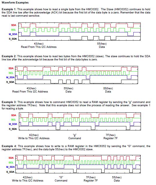
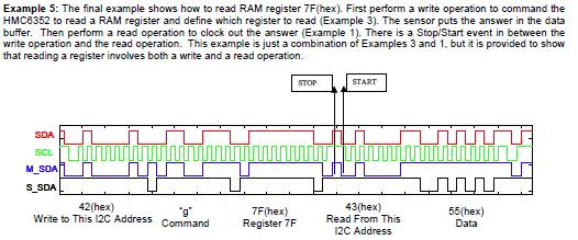
2 The 8th bit tells whether we are reading or writing to the address. One means reading from the slave and zero means writing to the slave. Note that the 7-bit address is in the upper 7 bits. To write data to a slave device: 1. Send a start sequence 2. Send the I2C address of the slave with the R/W bit low (even address) 3. Send the internal register number you want to write to. So if a slave module has 16 internal register you could send out the number 2 to write to register Send the data byte 5. [Optionally, send any further data bytes] 6. Send the stop sequence. To read data from a slave device: 1. Send a start sequence 2. Send the I2C address of the slave with the R/W bit low (even address) 3. Send the internal address of the register you want to read. 4. Send a start sequence again (repeated start) 2. Send the I2C address of the slave with the R/W bit high (odd address) 6. Read data byte. 7. Send the stop sequence. Note that if the slave cannot get data back in time for the clock signal which the master controls, it can hold the clock line low until the data is ready. The master will recognize this and wait for the clock line to go high to get the data. I 2 C on the HMC6352 Compass The 6352 acts as a slave I 2 C port at 100 KHz The write address is 42H and the read address is 43H The 6532 will operate from 2.7 to 5.2 volts on Vcc. The ARM is a 3.3 volt system so we will use this value. We need two 10K pull up resistors on the SCL and SDA I 2 C bus lines The following example from the 6532 data sheet shows the compass receiving a "Sleep" command ascii S

3 Commands to the 6532 are 1 to 3 bytes lone. The first byte is the command byte (an ascii character) and the next two bytes are a binary argument with the most significant byte first. The command are listed below. The 6532 has internal EEPROM which determines its operational parameters. These are: The EEPROM is shadowed in RAM. On start up the EEPROM values are copied into RAM. If you write to EEPROM your data is also copied to RAM. There are three operational modes determined by the Operation Mode Byte at 08H in EEPROM shadowed at 74H in RAM. The three modes are Standby, Query, and Continuous. Standby is the factory default and we will use only this mode in class. Here is the Operation Mode byte:
. When it gets this command it does a reading of the sensor.")
4 Bits 1 and 0 are 00 Standby, 01 Query, 10 Continuous. 11 is illegal. The Per.S/R is the periodic set/reset bit which does a recalibration every few minutes. This is probably not needed. Bits 5 and 6 determine the update rate in continuous mode. In Standby mode the 6532 waits for an 'A' command (get data). When it gets this command it does a reading of the sensor. At the next 'A' command it transmits the data. This data is always two-bytes of binary and may indicate either a heading or magnetometer data determined by the output data control byte in RAM at location 4EH. Note that the heading mode comes up by default on power up and this is what we will use in class. The two bytes in heading mode are in tenths of a degree from 0 to Writing to EEPROM is slow. Here are the delays required by each command. The following page gives examples of waveforms for reading and writing to the 6532.
5
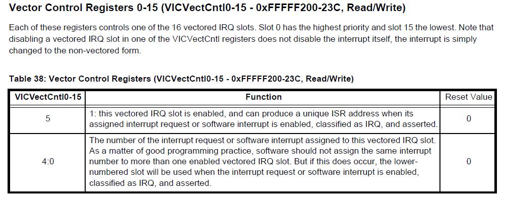
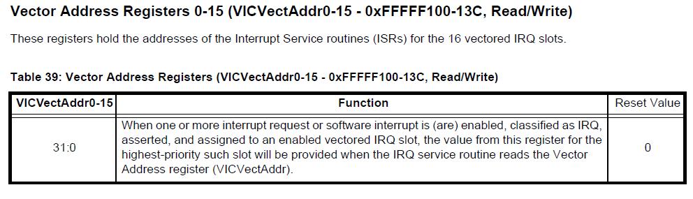
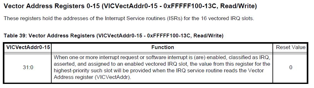
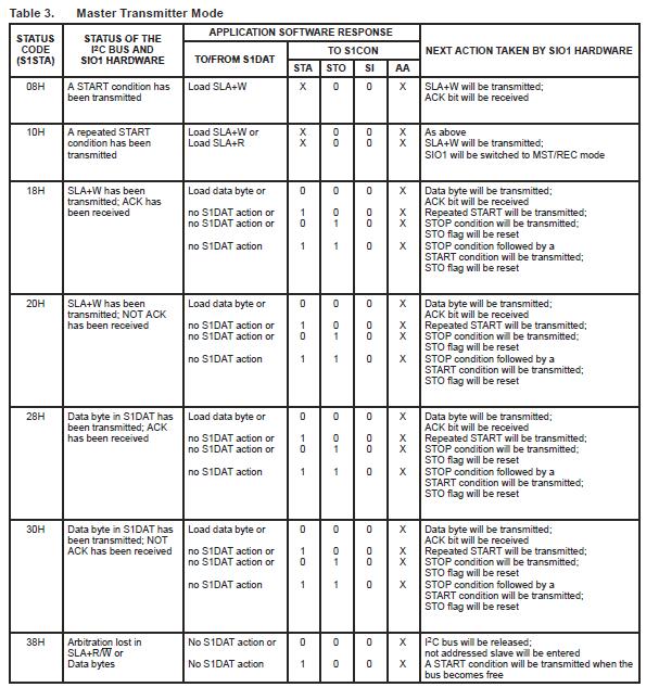
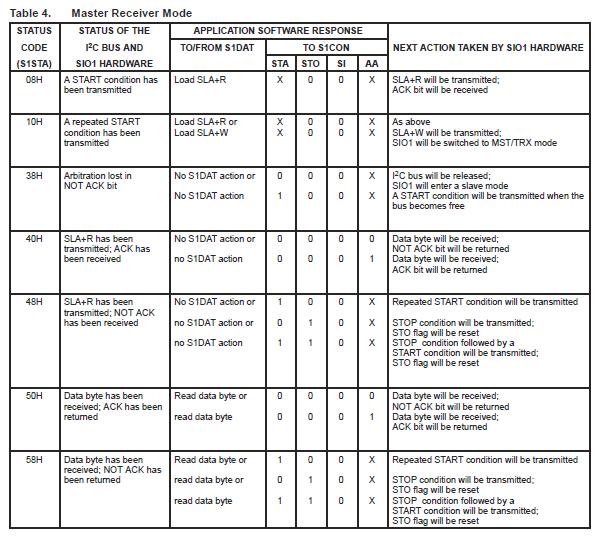
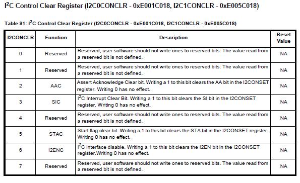
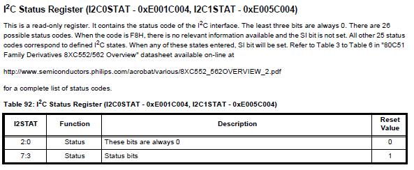
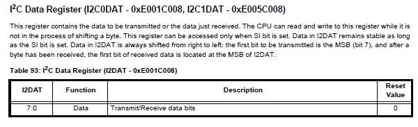
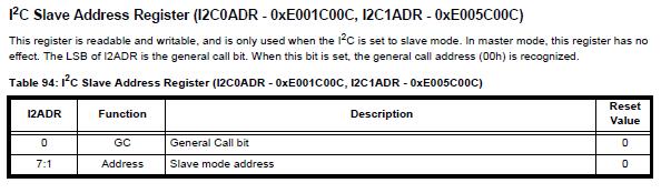
6 I 2 C on the ARM The ARM 2138 has two I 2 C ports SCL0 p22 and SDA0 p26 SCL1 p37 and SDA1 p41 We will use I 2 C0. From the Pin Function assignment table we set pinsel0 = 0x50; 2. To set up the interrupt we need to do the following three items: A) From the interrupt sources table determine the interrupt channel number for I 2 C. This is channel 9. For the interrupt control register we need to make bit 5 a 1 and set the first four bits to the channel number. VICVectCntl1 = 0x ; B) We need to set the address of the interrupt service routine into the interrupts address register. If we call this routine I2CISR we can do this by the following: VICVectAddr1 = (unsigned)i2cisr; C) We need to enable the appropriate interrupt. We are using channel 9 so we need a 1 in bit 9 of the interrupt enable register. VICIntEnable = 0x ; 3. Next we set up the bit rate for the I 2 C bus. This is determined as I 2 C clock rate PCLK/(SCLH+SCLL) = 100 KHz For our case CCLK is 4 x = MHz and if we set VPBDIV = 2 we get PCLK = MHz MHz/(SCLH + SCLL) = 100 KHz SCLH + SCLL = SCLH is the number of cycles of high time in the clock and SCLL is the number of cycles of low time in the clock. We can make the high time 150 and the low time at = 144. I2SCLH = 150; ISSCLL = 144; 4. At this point we are ready to enable the I 2 C transmission and send a command. To do this we will use the default standby mode and send an 'A' command. This causes the compass to read the sensors. A second 'A' command will cause the compass to transmit the data back as two bytes. There are seven registers that control the I 2 C bus. The five that we need to write are I2CONSET I 2 C Control Set I2EN is the enable bit, STA is the start bit, STO is the stop bit, SI is the interrupt flag, and AA is the assert acknowledge bit. I2CONCLR I 2 C Control Clear. Write all ones to this register to clear the system I2DAT I 2 C Data Register. 8-bits of data I2ADR I 2 C Slave Address Resister. Bits 1 to 7 have a 7 bit address. Bit 0 is zero to write and 1 to read. I2STAT The most significant 5 bits in this register are the status.

7
8
9
10
11
12
13
14
15 /* Interrupt driven I2C example for LPC2134 For use with the HMC6532 Compass module Writes the 'A' command to the I2C0 port twice and read two bytes of data. After that it toggles the upper 8-bits of port 1 indefinitely. */ #include <LPC213x.H> #include <stdarg.h> void I2CISR (void) irq ; //I2C interrupt routine //Starts Master and writes one byte of data void I2CWriteByte(unsigned int I2CAddr,unsigned char data); //Starts Master and reads two bytes of data void I2CReadBytes(unsigned int I2CAddr); unsigned char count, //To keep track of first and second byte in interrupt I2CAddress, //Address for reading and writing to compass memdata, //Data sent to Compass (commands) d1in, d2in, //Binary heading from compass lock; //Used to continue interrupt int main(void) {VPBDIV = 2; //PClk = CClk/2 IODIR1 = 0xFFFF0000; //Upper 16 bits of port 1 to output lock = 0; //Initilise the lock flag VICVectCntl1 = 0x ; //select a priority slot for a given interrupt VICVectAddr1 = (unsigned)i2cisr; //pass the address of the IRQ into the VIC slot VICIntEnable = 0x ; //enable interrupt PINSEL0 = 0x50; I2C0SCLH = 150; I2C0SCLL = 144; //Switch GPIO to I2C pins //Set bit rate Mhz/VPBDIV+SCLH+SCLL = /4+8+8 = 57.6Khz I2CWriteByte(0x42,'A'); //write 'A' command to the compass via I2C port I2CWriteByte(0x42,'A'); //write another 'A' I2CReadBytes(0x43); //read back two bytes of data //At this point there are two bytes of data in d2in,d1in I2C0CONCLR = 0x000000FF; //Clear all I2C settings I2C0CONSET = 0; //Disable I2C VICIntEnable = 0x ; //disable interrupt while(1) {IOPIN1 = IOPIN1 0xFF000000; //Toggle upper 8 bits of P1 to IOPIN1 = IOPIN1 & 0x00FFFFFF; // show that we got here //Write a byte to the I2C port void I2CWriteByte(unsigned int I2CAddr,unsigned char data) {while(lock == 1); //Wait for interrupt to signal end of I2C activity lock = 1; //Set I2C bus as active. Interrupt releases lock I2CAddress = I2CAddr; //Place address and data in Globals to be used by the interrupt memdata = data; I2C0CONCLR = 0x000000FF; //Clear all I2C settings I2C0CONSET = 0x ; //Enable the I2C interface I2C0CONSET = 0x ; //Start I2C //Read two bytes to global d1in and d2in void I2CReadBytes(unsigned int I2CAddr) {count = 1; // Read two bytes
16 while(lock == 1); //Wait for interrupt to signal end of I2C activity lock = 1; //Set I2C bus as active I2CAddress = I2CAddr; //Place address and data in Globals to be used by the interrupt I2C0CONCLR = 0x000000FF; //Clear all I2C settings I2C0CONSET = 0x ; //Enable the I2C interface I2C0CONSET = 0x ; //Start condition //I2C Interrupt Service Routine void I2CISR (void) irq //I2C interrupt routine {switch (I2C0STAT) //Read result code and switch to next action {// Start and Send byte conditions case ( 0x08): //Start bit I2C0CONCLR = 0x20; //Clear start bit I2C0DAT = I2CAddress; //Send address and write bit case (0x18): //Slave address+w, ACK I2C0DAT = memdata; //Write Memory start address to tx register case (0x20): //Salve address +W, Not ACK I2C0DAT = I2CAddress; //Resend address and write bi case (0x28): {I2C0CONSET = 0x10; //Stop condition lock = 0; //Signal end of I2C activity case (0x30) : //Data sent, NOT Ack I2C0DAT = memdata; //Write data to tx register //Receive byte conditions case (0x40) : //Slave Address +R, ACK I2C0CONSET = 0x04; //Enable ACK for data byte case (0x48) : //Slave Address +R, Not Ack I2C0CONSET = 0x20; //Resend Start condition case (0x50) : //Data Received, ACK if(count>0) {d2in = I2C0DAT; count--; else {d1in = I2C0DAT; I2C0CONSET = 0x10; //Stop condition lock = 0; //Signal end of I2C activity case (0x58): //Data Received, Not Ack I2C0CONSET = 0x20; // Resend Start condition default : I2C0CONCLR = 0x08; //Clear I2C interrupt flag VICVectAddr = 0x ; //Clear interrupt in
17
ARM HOW-TO GUIDE Interfacing I2C-7SEG with LPC2148 ARM
 ARM HOW-TO GUIDE Interfacing I2C-7SEG with LPC2148 ARM Contents at a Glance ARM7 LPC2148 Primer Board... 3 I2C (Inter Integrated Circuit)... 3 Seven Segment Display... 4 Interfacing I2C - Seven Segment
PCA9665; PCA9665A. 1. General description. 2. Features and benefits. Fm+ parallel bus to I 2 C-bus controller
 Rev. 4 29 September 2011 Product data sheet 1. General description 2. Features and benefits The PCA9665/PCA9665A serves as an interface between most standard parallel-bus microcontrollers/microprocesss
Tutorial for I 2 C Serial Protocol
 Tutorial for I 2 C Serial Protocol (original document written by Jon Valdez, Jared Becker at Texas Instruments) The I 2 C bus is a very popular and powerful bus used for communication between a master
DS1845 Dual NV Potentiometer and Memory
 www.maxim-ic.com FEATURES Two linear taper potentiometers -010 one 10k, 100 position & one 10k, 256 position -050 one 10k, 100 position & one 50k, 256 postition -100 one 10k, 100 position & one 100k, 256
The I2C BUS Interface
 The I 2 C BUS Interface ARSLAB - Autonomous and Robotic Systems Laboratory Dipartimento di Matematica e Informatica - Università di Catania, Italy santoro@dmi.unict.it L.S.M. 1 Course What is I 2 C? I
RL78 Serial interfaces
 RL78 Serial interfaces Renesas Electronics 00000-A Introduction Purpose This course provides an introduction to the RL78 serial interface architecture. In detail the different serial interfaces and their
Embedded Systems and Software. Serial Interconnect Buses I 2 C (SMB) and SPI
 and SPI") Embedded Systems and Software Serial Interconnect Buses I 2 C (SMB) and SPI I2C, SPI, etc. Slide 1 Provide low-cost i.e., low wire/pin count connection between IC devices There are many of serial bus standards
Embedded Systems and Software Serial Interconnect Buses I 2 C (SMB) and SPI I2C, SPI, etc. Slide 1 Provide low-cost i.e., low wire/pin count connection between IC devices There are many of serial bus standards
GT24C02. 2-Wire. 2Kb Serial EEPROM (Smart Card application)
") ADVANCED GT24C02 2-Wire 2Kb Serial EEPROM (Smart Card application) www.giantec-semi.com a0 1/19 Table of Content 1 FEATURES...3 2 DESCRIPTION...4 3 PIN CONFIGURATION...5 4 PIN DESCRIPTIONS...6 5 BLOCK
ADVANCED GT24C02 2-Wire 2Kb Serial EEPROM (Smart Card application) www.giantec-semi.com a0 1/19 Table of Content 1 FEATURES...3 2 DESCRIPTION...4 3 PIN CONFIGURATION...5 4 PIN DESCRIPTIONS...6 5 BLOCK
Manual iaq-engine Indoor Air Quality sensor
 Manual iaq-engine, Version 2.0 May 2011 (all data subject to change without notice) Manual iaq-engine Indoor Air Quality sensor Digital and analog I/O SMD type package Product summary iaq-engine is used
GT34C02. 2Kb SPD EEPROM
 Advanced GT34C02 2Kb SPD EEPROM Copyright 2010 Giantec Semiconductor Inc. (Giantec). All rights reserved. Giantec reserves the right to make changes to this specification and its products at any time without
Microtronix Avalon I 2 C
 Microtronix Avalon I 2 C User Manual 9-1510 Woodcock St. London, ON Canada N5H 5S1 www.microtronix.com This user guide provides basic information about using the Microtronix Avalon I 2 C IP. The following
LPC1300, FM+, Fast-mode Plus, I 2 C, Cortex-M3
 Rev. 01 17 December 2009 Application note Document information Info Keywords Abstract Content LPC1300, FM+, Fast-mode Plus, I 2 C, Cortex-M3 This application note introduces how to use the Fast-mode Plus
Lesson I2C. I²C (Inter-Integrated Circuit) Lab Assignment: I2C Slave Driver
 Lab Assignment: I2C Slave Driver") Lesson I2C I²C (Inter-Integrated Circuit) Lab Assignment: I2C Slave Driver I²C (Inter-Integrated Circuit) What is I 2 C I2C is pronounced "eye-squared see". It is also known as "TWI" because of the initial
Lesson I2C I²C (Inter-Integrated Circuit) Lab Assignment: I2C Slave Driver I²C (Inter-Integrated Circuit) What is I 2 C I2C is pronounced "eye-squared see". It is also known as "TWI" because of the initial
Microcontroller Systems. ELET 3232 Topic 23: The I 2 C Bus
 Microcontroller Systems ELET 3232 Topic 23: The I 2 C Bus Objectives To understand the basics of the I 2 C bus To understand the format of a serial transmission between I 2 C devices To understand how
RM24C64AF 64-Kbit 1.65V Minimum Non-volatile Fast Write Serial EEPROM I 2 C Bus
 64-Kbit 1.65V Minimum Non-volatile Fast Write Serial EEPROM I 2 C Bus Advance Datasheet Features Memory array: 64Kbit EEPROM-compatible non-volatile serial memory Single supply voltage: 1.65V - 2.2V 2-wire
17. I 2 C communication channel
 17. I 2 C communication channel Sometimes sensors are distant to the microcontroller. In such case it might be impractical to send analog signal from the sensor to the ADC included in the microcontroller
Introduction to I2C & SPI. Chapter 22
 Introduction to I2C & SPI Chapter 22 Issues with Asynch. Communication Protocols Asynchronous Communications Devices must agree ahead of time on a data rate The two devices must also have clocks that are
34 Series EEPROM Application Note. 1. Introduction. 2. Power supply & power on reset
 1. Introduction his application note provides assistance and guidance on how to use GIANEC I 2 C serial EEPROM products. he following topics are discussed one by one: Power supply & power on reset Power
The I2C controller supports only Master function. It supports the 7-bits/10-bits addressing mode and support general call address. The maximum clock f
 Chapter 52 I2C Interface 52.1 Overview The Inter-Integrated Circuit (I2C) is a two wired (SCL and SDA), bi-directional serial bus that provides an efficient and simple method of information exchange between
SILICON MICROSTRUCTURES
 Digital Communication with SM5800 Series Parts OVERVIEW The SM5800 series pressure product offers the corrected pressure output in both analog and digital formats. Accessing the analog output is an easy
VORAGO VA108x0 I 2 C programming application note
 AN1208 VORAGO VA108x0 I 2 C programming application note MARCH 14, 2017 Version 1.1 VA10800/VA10820 Abstract There are hundreds of peripheral devices utilizing the I 2 C protocol. Most of these require
Two Wire Interface (TWI) also commonly called I2C
 also commonly called I2C") (TWI) also commonly called I2C MSP432 I2C 2 tj MSP432 I2C ARM (AMBA Compliant) 8 bit transmission word 7/10 bit addressing Multi-master/slave modes 4 slave addresses 4 eusci-b modules 3 tj Overview 8 bit
(TWI) also commonly called I2C MSP432 I2C 2 tj MSP432 I2C ARM (AMBA Compliant) 8 bit transmission word 7/10 bit addressing Multi-master/slave modes 4 slave addresses 4 eusci-b modules 3 tj Overview 8 bit
Theory of Operation STOP CONDITION
 AVR 300: Software I 2 C Master Interface Features Uses Interrupts Supports rmal And Fast Mode Supports Both 7-Bit and 10-Bit Addressing Supports the Entire AVR Microcontroller Family Introduction The need
DS1676 Total Elapsed Time Recorder, Erasable
 www.dalsemi.com Preliminary DS1676 Total Elapsed Time Recorder, Erasable FEATURES Records the total time that the Event Input has been active and the number of events that have occurred. Volatile Elapsed
MOS INTEGRATED CIRCUIT
 DATA SHEET MOS INTEGRATED CIRCUIT µpd6708 IEBus (Inter Equipment Bus ) PROTOCOL CONTROL LSI DESCRIPTION The µpd6708 is a peripheral LSI for microcontrollers that controls the protocol of the IEBus. This
BL24C02/BL24C04/BL24C08/BL24C16
 BL24C02/BL24C04/BL24C08/BL24C16 2K bits (256 X 8) / 4K bits (512 X 8) / 8K bits (1024 X 8) / 16K bits (2048 X 8) Two-wire Serial EEPROM Features Two-wire Serial Interface VCC = 1.8V to 5.5V Bi-directional
SPI (Serial & Peripheral Interface)
") SPI (Serial & Peripheral Interface) What is SPI SPI is a high-speed, full-duplex bus that uses a minimum of 3 wires to exchange data. The popularity of this bus rose when SD cards (and its variants ie:
SPI (Serial & Peripheral Interface) What is SPI SPI is a high-speed, full-duplex bus that uses a minimum of 3 wires to exchange data. The popularity of this bus rose when SD cards (and its variants ie:
CMPS03 - Compass Module
 CMPS03 - Compass Module For documentation on CMPS03 revisions prior to Rev14, click here Earlier versions can be identified by the presence of the silver 8MHz ceramic resonator in the middle of the PCB,
External I2C. User Guide. 05/2014 Capital Microelectronics, Inc. China
 External I2C User Guide 05/2014 Capital Microelectronics, Inc. China Contents Contents... 2 1 Introduction... 3 2 External I2C Overview... 4 2.1 Pin Description... 4 2.1.1 M5 I2C Interface... 4 2.1.2 M7
DHANALAKSHMI COLLEGE OF ENGINEERING, CHENNAI DEPARTMENT OF ELECTRICAL AND ELECTRONICS ENGINEERING. EE Microcontroller Based System Design
 DHANALAKSHMI COLLEGE OF ENGINEERING, CHENNAI DEPARTMENT OF ELECTRICAL AND ELECTRONICS ENGINEERING EE6008 - Microcontroller Based System Design UNIT III PERIPHERALS AND INTERFACING PART A 1. What is an
EZ I 2 C Slave. Features. General Description. When to use a EZ I 2 C Slave 1.50
 PSoC Creator Component Data Sheet EZ I 2 C Slave 1.50 Features Industry standard Philips I 2 C bus compatible interface Emulates common I 2 C EEPROM interface Only two pins (SDA and SCL) required to interface
BV4205. I2C-10 Channel A to D. Product specification. January 2008 V0.a. ByVac Page 1 of 10
 Product specification January 2008 V0.a ByVac Page 1 of 10 Contents 1. Introduction...4 2. Features...4 3. Physical Specification...4 3.1. Factory (hardware) reset...4 3.2. Analogue Inputs...4 3.3. Voltage
ARM HOW-TO GUIDE Interfacing Switch with LPC2148 ARM
 ARM HOW-TO GUIDE Interfacing Switch with LPC48 ARM Contents at a Glance ARM7 LPC48 Primer Board... 3 Switch... 3 Interfacing Switch... 4 Interfacing Switch with LPC48... 5 Pin Assignment with LPC48...
AN Entering ISP mode from user code. Document information. ARM ISP, bootloader
 Rev. 03 13 September 2006 Application note Document information Info Keywords Abstract Content ARM ISP, bootloader Entering ISP mode is normally done by sampling a pin during reset. This application note
Microcontrollers and Interfacing
 Microcontrollers and Interfacing Week 10 Serial communication with devices: Serial Peripheral Interconnect (SPI) and Inter-Integrated Circuit (I 2 C) protocols College of Information Science and Engineering
Lecture 25 March 23, 2012 Introduction to Serial Communications
 Lecture 25 March 23, 2012 Introduction to Serial Communications Parallel Communications Parallel Communications with Handshaking Serial Communications Asynchronous Serial (e.g., SCI, RS-232) Synchronous
GT24C WIRE. 1024K Bits. Serial EEPROM
 GT24C1024 2-WIRE 1024K Bits Serial EEPROM Copyright 2013 Giantec Semiconductor Inc. (Giantec). All rights reserved. Giantec reserves the right to make changes to this specification and its products at
EPT-200TMP-TS-U2 TMP102 Temperature Sensor Docking Board Data Sheet
 EPT-2TMP-TS-U2 TMP12 Temperature Sensor Docking Board Data Sheet This docking board is based on the TMP12 Temperature Sensor chip from Texas Instruments. It can measure the ambient temperature between
DS 1682 Total Elapsed Time Recorder with Alarm
 DS 1682 Total Elapsed Time Recorder with Alarm www.dalsemi.com FEATURES Records the total time that the Event Input has been active and the number of events that have occurred. Volatile Elapsed Time Counter
The IIC interface based on ATmega8 realizes the applications of PS/2 keyboard/mouse in the system
 Available online at www.sciencedirect.com Procedia Engineering 16 (2011 ) 673 678 International Workshop on Automobile, Power and Energy Engineering The IIC interface based on ATmega8 realizes the applications
1.3inch OLED User Manual
 1.3inch OLED User Manual 1. Key Parameters Table 1: Key Parameters Driver Chip SH1106 Interface 3-wire SPI 4-wire SPI I2C Resolution 128*64 Display Size 1.3 inch Dimension 29mm*33mm Colors Yellow, Blue
Implementation of MCU Invariant I2C Slave Driver Using Bit Banging
 Implementation of MCU Invariant I2C Slave Driver Using Bit Banging Arindam Halder, Ranjan Dasgupta Innovation Lab, TATA Consultancy Services, Ltd. Kolkata, India arindam.halder@tcs.com,ranjan.dasgupta@tcs.com
VBattery 7 VCC V DD IRLED IS31SE5001 SDA SCL INTB SDB. Figure 1 Typical Application Circuit
 IR SENSOR FOR TOUCHLESS PROXIMITY July 2013 GENERAL DESCRIPTION The IS31SE5001 is a low-power, reflectance-based infrared light sensor with advanced signal processing and digital output. The sensor can
ArduCAM USB Camera Shield
 ArduCAM USB Camera Shield User Guide Rev 1.0, April 2017 Table of Contents 1 Introduction... 2 2 Hardware Installation... 2 2.1 Primary Camera Interface... 2 2.2 Secondary Camera Interface... 3 3 Device
EE 456 Fall, Table 1 SPI bus signals. Figure 1 SPI Bus exchange of information between a master and a slave.
 EE 456 Fall, 2009 Notes on SPI Bus Blandford/Mitchell The Serial Peripheral Interface (SPI) bus was created by Motorola and has become a defacto standard on many microcontrollers. This is a four wire bus
The Cubesat Internal bus: The I2C
 The Cubesat Internal bus: The I2C Description: The purpose of this document is to describe the internal bus on the Cubesat. The internal bus has been chosen to be the I2C bus Interconnected Integrated
I 2 C Application Note in Protocol B
 I 2 C Application Note in Protocol B Description This document is a reference for a possible coding method to achieve pressure, temperature, and status for SMI part readings using I 2 C. This SMI Protocol
I2C a learn.sparkfun.com tutorial
 I2C a learn.sparkfun.com tutorial Available online at: http://sfe.io/t82 Contents Introduction Why Use I2C? I2C at the Hardware Level Protocol Resources and Going Further Introduction In this tutorial,
KNJN I2C bus development boards
 KNJN I2C bus development boards 2005, 2006, 2007, 2008 KNJN LLC http://www.knjn.com/ Document last revision on December 5, 2008 R22 KNJN I2C bus development boards Page 1 Table of Contents 1 The I2C bus...4
GT24C256 2-WIRE. 256K Bits. Serial EEPROM
 GT24C256 2-WIRE 256K Bits Serial EEPROM Copyright 2013 Giantec Semiconductor Inc. (Giantec). All rights reserved. Giantec reserves the right to make changes to this specification and its products at any
AN-895 APPLICATION NOTE
 APPLICATION NOTE One Technology Way P.O. Box 9106 Norwood, MA 02062-9106, U.S.A. Tel: 781.329.4700 Fax: 781.461.3113 www.analog.com ADuC702x MicroConverter I 2 C -Compatible Interface by Michael Looney
Application Note: AZD025 IQ Switch - ProxSense TM Series I2C Example Code for the IQS222
 1. Introduction Application Note: AZD025 IQ Switch - ProxSense TM Series I2C Example Code for the IQS222 The IQS222 uses a 100 KHz bi-directional 2-wire bus and data transmission protocol. The serial protocol
DS1682 Total-Elapsed-Time Recorder with Alarm
 www.maxim-ic.com GENERAL DESCRIPTION The DS1682 is an integrated elapsed-time recorder containing a factory-calibrated, temperaturecompensated RC time base that eliminates the need for an external crystal.
Temperature Sensor TMP2 PMOD Part 1
 Temperature Sensor TMP2 PMOD Part 1 Overview of the Temperature Sensor and I 2 C Interfacing Reference Sites: Diligent Temp2 PMOD: http://www.digilentinc.com/products/detail.cfm?navpath=2,401,961&prod=pmod-tmp2
HDS Series I2C Application Notes
 HDS Series I2C Application Notes I2C Bus Interface Introduction The I2C interface of the HDS series of power supplies allows remote control and monitoring and provides the following features: 1) Retrieving
or between microcontrollers)
") : Communication Interfaces in Embedded Systems (e.g., to interface with sensors and actuators or between microcontrollers) Spring 2016 : Communication Interfaces in Embedded Systems Spring (e.g., 2016
: Communication Interfaces in Embedded Systems (e.g., to interface with sensors and actuators or between microcontrollers) Spring 2016 : Communication Interfaces in Embedded Systems Spring (e.g., 2016
Laboratory 5 Communication Interfaces
 Laboratory 5 Communication Interfaces Embedded electronics refers to the interconnection of circuits (micro-processors or other integrated circuits) with the goal of creating a unified system. In order
How to Implement I 2 C Serial Communication Using Intel MCS-51 Microcontrollers
 APPLICATION NOTE How to Implement I 2 C Serial Communication Using Intel MCS-51 Microcontrollers SABRINA D QUARLES APPLICATIONS ENGINEER April 1993 Order Number 272319-001 Information in this document
DS WIRE INTERFACE 11 DECOUPLING CAP GND
 Rev ; 4/3 Hex Nonvolatile Potentiometer with General Description The contains six 256-position nonvolatile (NV) potentiometers, 64 bytes of NV user EEPROM memory, and four programmable NV I/O pins. The
PCI to SH-3 AN Hitachi SH3 to PCI bus
 PCI to SH-3 AN Hitachi SH3 to PCI bus Version 1.0 Application Note FEATURES GENERAL DESCRIPTION Complete Application Note for designing a PCI adapter or embedded system based on the Hitachi SH-3 including:
LB5900 Series Power Sensor SPI & I2C Interface Guide
 LB5900 Series Power Sensor SPI & I2C Interface Guide TABLE OF CONTENTS TABLE OF CONTENTS... 1 NOTICE... 4 GENERAL... 5 Sensor Power... 6 Data Line Electrical Specifications... 6 Commands, Data Transmission
BV4615. Dual Interface Zero Keypad. Product specification. Dec 2009 V0.a. ByVac Page 1 of 11
 Product specification Dec 2009 V0.a ByVac Page 1 of 11 Contents 1. Introduction...3 2. Features...3 3. Physical Specification...3 3.1. Serial connector...3 3.2. Multiple Devices...4 3.3. I2C...4 4. Output
Figure 1 Typical Application Circuit
 4-CH CAPACITIVE TOUCH SENSOR WITH AUTO CALIBRATION August 2015 GENERAL DESCRIPTION The IS31SE5104 is a low power, fully integrated 4-channel solution for capacitive touch button applications. The chip
FM24C16C-GTR. 16Kb Serial 5V F-RAM Memory. Features. Description. Pin Configuration NC NC NC VSS VDD WP SCL SDA. Ordering Information.
 Preliminary FM24C16C 16Kb Serial 5V F-RAM Memory Features 16K bit Ferroelectric Nonvolatile RAM Organized as 2,048 x 8 bits High Endurance (10 12 ) Read/Write Cycles 36 year Data Retention at +75 C NoDelay
DS1625. Digital Thermometer and Thermostat FEATURES PIN ASSIGNMENT
 DS1625 Digital Thermometer and Thermostat FEATURES Temperature measurements require no external components Measures temperatures from 55 C to +125 C in 0.5 C increments. Fahrenheit equivalent is 67 F to
I2C interface Tutorial
 UG108: Praxis II January 2013 Asian Institute of Technology Undergraduate Program Handout: I2C interface Instructor: Chaiyaporn Silawatchananai, Matthew N. Dailey I2C interface Tutorial Introduction: In
BV4218. I2C-LCD & Keypad. Product specification. December 2008 V0.a. ByVac 2006 ByVac Page 1 of 9
 Product specification December 2008 V0.a ByVac 2006 ByVac Page 1 of 9 Contents 1. Introduction...3 2. Features...3 3. Electrical Specification...3 4. I2C set...4 5. The LCD Set...5 5.1. 1...5 5.2. 2...5
Hello, and welcome to this presentation of the STM32 I²C interface. It covers the main features of this communication interface, which is widely used
 Hello, and welcome to this presentation of the STM32 I²C interface. It covers the main features of this communication interface, which is widely used to connect devices such as microcontrollers, sensors,
I2C. I2C, sometimes IIC or I 2 C, stands for inter IC. 2-line bus, clock (SCL) and data (SDA) Devices individually addressable
 and data (SDA) Devices individually addressable") I2C I2C, sometimes IIC or I 2 C, stands for inter IC 2-line bus, clock (SCL) and data (SDA) Devices individually addressable Not sensitive to clock speed No bus power contention Sources http://www.robot-electronics.co.uk/i2c-tutorial
I2C I2C, sometimes IIC or I 2 C, stands for inter IC 2-line bus, clock (SCL) and data (SDA) Devices individually addressable Not sensitive to clock speed No bus power contention Sources http://www.robot-electronics.co.uk/i2c-tutorial
Embedded Workshop 10/28/15 Rusty Cain
 2 IC Embedded Workshop 10/28/15 Rusty Cain Set up for Workshop: Please Sign in on Sheet. Please include your email. While you are waiting for the Workshop to begin 1. Make sure you are connected to the
USB-I2C USB to I2C Communications Module Technical Specification
 Page 1 of 7 USB-I2C USB to I2C Communications Module Technical Specification The USB-I2C module provides a complete interface between your PC and the I2C bus. The module is self powered from the USB cable
GPIO-MM User Manual. FPGA-based PC/104 Counter/Timer and Digital I/O Module. User Manual v1.04
 GPIO-MM User Manual FPGA-based PC/104 Counter/Timer and Digital I/O Module User Manual v1.04 Copyright 2006 Diamond Systems Corporation 1255 Terra Bella Ave. Mountain View, CA 94043 Tel (650) 810-2500
RX Family, RL78 Family
 Introduction APPLICATION NOTE This application note explains the method of controlling R1EV24xxx, R1EX24xxx, and HN58X24xxx series I 2 C serial EEPROM, manufactured by Renesas Electronics, by using a Renesas
THE INTERNATIONAL JOURNAL OF SCIENCE & TECHNOLEDGE
 THE INTERNATIONAL JOURNAL OF SCIENCE & TECHNOLEDGE Assertion Based Verification of I2C Master Bus Controller with RTC Sagar T. D. M.Tech Student, VLSI Design and Embedded Systems BGS Institute of Technology,
Debounced 8 8 Key-Scan Controller
 Debounced 8 8 Key-Scan Controller Description The SN7326 is a 64 key, key-scan controller. It offloads the burden of keyboard scanning from the host processor. The SN7326 supports keypad matrix of up to
Interfacing the NM24C16 Serial EEPROM to the microcontroller. Interfacing the NM24C16 Serial EEPROM to the 8031 Microcontroller AN-957
 Interfacing the NM24C16 Serial EEPROM to the 8031 Microcontroller INTRODUCTION This applications note describes an interface between the National Semiconductor NM24C16 serial EEPROM and an 8031 microcontroller
Interfacing Z8 Encore! XP MCUs with an I 2 C-Based Character LCD
 Application Note Interfacing Z8 Encore! XP MCUs with an I 2 C-Based Character LCD AN014902-1207 Abstract This Application Note describes APIs for interfacing one or more I 2 C-based character LCDs with
2-Axis Compass with Algorithms HMC6352
 2-Axis Compass with Algorithms HMC6352 The Honeywell HMC6352 is a fully integrated compass module that combines 2-axis magneto-resistive sensors with the required analog and digital support circuits, microprocessor
FM24CL04 4Kb FRAM Serial Memory
 4Kb FRAM Serial Memory Features 4K bit Ferroelectric Nonvolatile RAM Organized as 512 x 8 bits Unlimited Read/Writes 45 Year Data Retention NoDelay Writes Advanced High-Reliability Ferroelectric Process
DS Wire Digital Thermometer and Thermostat
 www.maxim-ic.com FEATURES Temperature measurements require no external components with ±1 C accuracy Measures temperatures from -55 C to +125 C; Fahrenheit equivalent is -67 F to +257 F Temperature resolution
FM24C16B-GTR. 16Kb Serial 5V F-RAM Memory. Features. Pin Configuration. Description. Ordering Information NC NC NC VSS VDD WP SCL SDA.
 Preliminary FM24C16B 16Kb Serial 5V F-RAM Memory Features 16K bit Ferroelectric Nonvolatile RAM Organized as 2,048 x 8 bits High Endurance (10 12 ) Read/Write Cycles 38 year Data Retention NoDelay Writes
FM24C Kb FRAM Serial Memory Features
 Preliminary FM24C512 512Kb FRAM Serial Memory Features 512Kbit Ferroelectric Nonvolatile RAM Organized as 65,536 x 8 bits High Endurance 10 Billion (10 10 ) Read/Writes 45 year Data Retention NoDelay Writes
Manual iaq-core Indoor Air Quality sensor module
 Manual iaq-core Indoor Air Quality sensor module I²C interface SMD type package Reflow capable Product summary The iaq-core is used to measure VOC levels and provide CO 2 equivalent and TVOC equivalent
Section 16. Basic Sychronous Serial Port (BSSP)
") M 16 Section 16. Basic Sychronous Serial Port (BSSP) BSSP HIGHLIGHTS This section of the manual contains the following major topics: 16.1 Introduction...16-2 16.2 Control Registers...16-3 16.3 SPI Mode...16-6
M 16 Section 16. Basic Sychronous Serial Port (BSSP) BSSP HIGHLIGHTS This section of the manual contains the following major topics: 16.1 Introduction...16-2 16.2 Control Registers...16-3 16.3 SPI Mode...16-6
HT16K23 RAM Mapping 20 4/16 8 LCD Controller Driver with Keyscan
 RAM Mapping 20 4/16 8 LCD Controller Driver with Keyscan Feature Logic voltage: 2.4V~5.5V Integrated RC oscillator Various display modes Max. 20 4 patterns, 20 segments, 4 commons, 1/3 bias, 1/4 duty Max.
M16C/26 APPLICATION NOTE. Interfacing with 1-Wire Devices. 1.0 Abstract. 2.0 Introduction Wire Interface. 3.1 Hardware
 APPLICATION NOTE M16C/26 1.0 Abstract The following article introduces and shows an example of how to interface Renesas 16-bit microcontrollers (MCU) to a 1-wire device. A demo program developed for the
KJ Joystick I 2 C Development Kit Programming and Application Note. Knowles Acoustics Maplewood Drive Itasca, IL 60143
 Joystick I 2 C Development Kit Programming and Application Note KJ 33000 Installed within the Development Kit. Knowles Acoustics 1151 Maplewood Drive Itasca, IL 60143 Sheet 1 of 5 1. DESCRIPTION AND APPLICATION
I 2 C Port Expander with Eight Inputs. Features
 EVALUATION KIT AVAILABLE MAX7319 General Description The MAX7319 2-wire serial-interfaced peripheral fea-tures eight input ports with selectable internal pullups, overvoltage protection to +6V, and transition
USB-910H API DLL and Include File Reference Manual
 USB-910H API DLL and Include File Reference Manual APPLICABLE ADAPTERS This Application Note applies to the following Keterex products: KXUSB-910H. AN2101 Application Note INTRODUCTION The Keterex USB-910H
I 2 C Communication. Embedded Systems Interfacing. 25 October 2011
 25 October 2011 frametitletypical System Specifications Version 1.0 1992 Up to 400 Kbps 10 bit addresses Version 2.0 1998 Up to 3.4 Mbps New signal levels for High-speed operation Version 2.1 2000 Some
Color 7 click. PID: MIKROE 3062 Weight: 19 g
 Color 7 click PID: MIKROE 3062 Weight: 19 g Color 7 click is a very accurate color sensing Click board which features the TCS3472 color light to digital converter with IR filter, from ams. It contains
Design and development of embedded systems for the Internet of Things (IoT) Fabio Angeletti Fabrizio Gattuso
 Fabio Angeletti Fabrizio Gattuso") Design and development of embedded systems for the Internet of Things (IoT) Fabio Angeletti Fabrizio Gattuso Microcontroller It is essentially a small computer on a chip Like any computer, it has memory,
Design and development of embedded systems for the Internet of Things (IoT) Fabio Angeletti Fabrizio Gattuso Microcontroller It is essentially a small computer on a chip Like any computer, it has memory,
Learn how to communicate
 USART 1 Learn how to communicate Programmed I/O (Software Polling) Interrupt Driven I/O Direct Memory Access (DMA) 2 Programmed I/O (Polling) Processor must read and check I/O ready bits for proper value
XRA BIT I2C/SMBUS GPIO EXPANDER WITH INTEGRATED LEVEL SHIFTERS
 SEPTEMBER 2011 REV. 1.0.0 GENERAL DESCRIPTION The XRA1207 is a 16-bit GPIO expander with an I 2 C/ SMBus interface. After power-up, the XRA1207 has internal 100K ohm pull-up resistors on each pin that
IV B.Tech. I Sem (R13) ECE : Embedded Systems : UNIT -4 1 UNIT 4
 ECE : Embedded Systems : UNIT -4 1 UNIT 4") IV B.Tech. I Sem (R13) ECE : Embedded Systems : UNIT -4 1 UNIT 4 4.1. Serial data communication basics ----------- 1 4.2. UART ------------------------------------------------ 4 4.3. Serial Peripheral
IV B.Tech. I Sem (R13) ECE : Embedded Systems : UNIT -4 1 UNIT 4 4.1. Serial data communication basics ----------- 1 4.2. UART ------------------------------------------------ 4 4.3. Serial Peripheral
Dallas Semiconductor DS1307 Real Time Clock. The DS 1307 is a real-time clock with 56 bytes of NV (nonvolatile)
") Using the MC9S12 IIC Bus with DS 1307 Real Time Clock DS1307 Data Sheet Asynchronous Serial Communications The MC9S12 Serial Communications Interface (SCI) Dallas Semiconductor DS1307 Real Time Clock The
Using the MC9S12 IIC Bus with DS 1307 Real Time Clock DS1307 Data Sheet Asynchronous Serial Communications The MC9S12 Serial Communications Interface (SCI) Dallas Semiconductor DS1307 Real Time Clock The
Growing Together Globally Serial Communication Design In Embedded System
 Growing Together Globally Serial Communication Design In Embedded System Contents Serial communication introduction......... 01 The advantages of serial design......... 02 RS232 interface......... 04 RS422
GT24C64 2-WIRE. 64K Bits. Serial EEPROM
 GT24C64 2-WIRE 64K Bits Serial EEPROM Copyright 2013 Giantec Semiconductor Inc. (Giantec). All rights reserved. Giantec reserves the right to make changes to this specification and its products at any
AN Full-duplex software UART for LPC2000. Document information
 Full-duplex software UART for LPC2000 Rev. 01 17 January 2008 Application note Document information Info Keywords Abstract Content LPC2000, UART, software This application note illustrates how a simple
XRA1201/1201P 16-BIT I2C/SMBUS GPIO EXPANDER
 SEPTEMBER 2011 REV. 1.0.0 GENERAL DESCRIPTION The XRA1201/1201P is a 16-bit GPIO expander with an I 2 C/SMBus interface. After power-up, the XRA1201 has internal 100K ohm pull-up resistors on each pin