MultiConnect Cell 100 Series MTC-H5 User Guide
|
|
|
- Kellie Day
- 5 years ago
- Views:
Transcription

1 MultiConnect Cell 100 Series MTC-H5 User Guide
2 MULTICONNECT CELL SERIES 100 USER GUIDE MultiConnect Cell Series 100 User Guide Model: MTC-H5 Part Number: S Copyright This publication may not be reproduced, in whole or in part, without the specific and express prior written permission signed by an executive officer of Multi-Tech Systems, Inc. All rights reserved. Copyright 2014 by Multi-Tech Systems, Inc. Multi-Tech Systems, Inc. makes no representations or warranties, whether express, implied or by estoppels, with respect to the content, information, material and recommendations herein and specifically disclaims any implied warranties of merchantability, fitness for any particular purpose and noninfringement. Multi-Tech Systems, Inc. reserves the right to revise this publication and to make changes from time to time in the content hereof without obligation of Multi-Tech Systems, Inc. to notify any person or organization of such revisions or changes. Legal Notices The Multi-Tech products are not designed, manufactured or intended for use, and should not be used, or sold or re-sold for use, in connection with applications requiring fail-safe performance or in applications where the failure of the products would reasonably be expected to result in personal injury or death, significant property damage, or serious physical or environmental damage. Examples of such use include life support machines or other life preserving medical devices or systems, air traffic control or aircraft navigation or communications systems, control equipment for nuclear facilities, or missile, nuclear, biological or chemical weapons or other military applications ( Restricted Applications ). Use of the products in such Restricted Applications is at the user s sole risk and liability. MULTI-TECH DOES NOT WARRANT THAT THE TRANSMISSION OF DATA BY A PRODUCT OVER A CELLULAR COMMUNICATIONS NETWORK WILL BE UNINTERRUPTED, TIMELY, SECURE OR ERROR FREE, NOR DOES MULTI-TECH WARRANT ANY CONNECTION OR ACCESSIBILITY TO ANY CELLULAR COMMUNICATIONS NETWORK. MULTI-TECH WILL HAVE NO LIABILITY FOR ANY LOSSES, DAMAGES, OBLIGATIONS, PENALTIES, DEFICIENCIES, LIABILITIES, COSTS OR EXPENSES (INCLUDING WITHOUT LIMITATION REASONABLE ATTORNEYS FEES) RELATED TO TEMPORARY INABILITY TO ACCESS A CELLULAR COMMUNICATIONS NETWORK USING THE PRODUCTS. Contacting Multi-Tech Knowledge Base The Knowledge Base provides immediate access to support information and resolutions for all Multi-Tech products. Visit Support Portal To create an account and submit a support case directly to our technical support team, visit: Support Business Hours: M-F, 8am to 5pm CT Country By By Phone Europe, Middle East, Africa: support@multitech.co.uk +(44) U.S., Canada, all others: support@multitech.com (800) or (763) Warranty To read the warranty statement for your product, visit For other warranty options, visit World Headquarters Multi-Tech Systems, Inc Woodale Drive, Mounds View, MN Phone: (800) or (763) Fax (763) MultiConnect Cell 100 Series MTC-H5 User Guide
3 CONTENTS Contents Product Overview... 5 About the MultiConnect Cell Modem... 5 Documentation... 5 Descriptions of LEDs... 5 Side Panels... 6 Specifications... 7 Power Draw MTC-H Dimensions Serial USB Safety Warnings Radio Frequency (RF) Safety Interference with Pacemakers and Other Medical Devices Potential interference Precautions for pacemaker wearers Antenna Installing and Using the Device Installing the Device Placing Serial Devices in Power Save Mode USB Cable Recommendations Installing a SIM Card Removing a SIM Card Mounting Device to Flat Surface Using Diversity Antenna and Activation Information Cellular Antenna Information Authorized Antenna/Antenna Specifications for Cellular Bands G Antenna Requirements/Specifications Antenna Antenna System Cellular Devices Account Activation for Cellular Devices Device Phone Number Using Linux Shell Commands Testing Serial Ports Create a PPP Connection Example MultiConnect Cell 100 Series MTC-H5 User Guide 3
4 CONTENTS Configuring and Communicating with Your Device Interacting with Your Device Overview Before You Begin Using Command Mode and Online Data Mode Verifying Signal Strength Example Checking Network Registration Sending and Receiving Data Connecting Device to TCP Server as TCP Client Configuring Device as UDP Listener to Accept UDP Client Connections Configuring Device as UDP Client to Connect to UDP Server Configuring Device as UDP Listener to Accept UDP Client Connections Transferring FTP File to FTP Server Downloading File from FTP Server Reading, Writing and Deleting Messages Reading Text Messages Sending Text Messages Deleting Messages Regulatory Information Industry Canada Class B Notice Industry Canada and FCC CFR Part 15 Regulation Class B Devices FCC Interference Notice Notice for Devices that Use Aeris Radios EMC, Safety, and R&TTE Directive Compliance Restriction of the Use of Hazardous Substances (RoHS) REACH Statement Registration of Substances Substances of Very High Concern (SVHC) Waste Electrical and Electronic Equipment Statement WEEE Directive Instructions for Disposal of WEEE by Users in the European Union Information on HS/TS Substances According to Chinese Standards Information on HS/TS Substances According to Chinese Standards (in Chinese) MultiConnect Cell 100 Series MTC-H5 User Guide
5 PRODUCT OVERVIEW Product Overview About the MultiConnect Cell Modem The MultiConnect Cell 100 Series MTC-H5 cellular modems are ready-to-deploy, standalone HSPA+ modems that provide wireless data communication. The modems integrate seamlessly with virtually any application, and are useful for automated applications, such as remote diagnostics and remote monitoring. They are available with RS- 232 and USB connectors. The MultiConnect Cell cellular modems are based on industry-standard open interfaces. Documentation The following documentation is available on the Multi-Tech Installation Resources website at Document MultiConnect Cell User Guide Description This document. Provides an overview, safety and regulatory information, schematics, and general device information. HSPA+ AT Commands You can configure the device using the HSPA+ AT Commands. These commands are Reference Guide documented in the Reference Guide part number S Descriptions of LEDs Devices that have a serial connector have the following LEDs: Power TR CD LS Devices that have a USB connector have the following LEDs: Power MultiConnect Cell 100 Series MTC-H5 User Guide 5
 Not Lit Lit Data is not being transmitted. Blinks when data is being transmitted. CD (Carrier Detect) Not lit Lit Data connection is not established.")
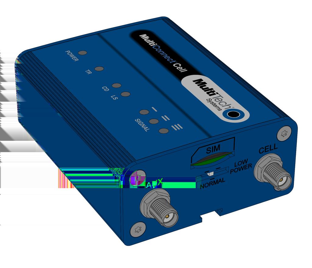
6 PRODUCT OVERVIEW LS The tables that follow provide details about what the LEDs indicate. Power Not lit Lit DC power not present. DC power present. TR (Terminal Ready) Not Lit Lit Data is not being transmitted. Blinks when data is being transmitted. CD (Carrier Detect) Not lit Lit Data connection is not established. Data connection is established. LS (Link Status) Not lit Continuously lit Slow blink Fast blink There is no power to the cellular radio. Powered and connected, but not transmitting or receiving. Powered and searching for a connection. Transmitting or receiving. Signal ALL OFF There is no power to the cellular radio. Bar 1 ON Very weak signal (7 < = RSSI <14). Bar 1 and 2 ON Weak signal (15 < = RSSI <23). Bar 1, 2, 3 ON Good signal (24 <= RSSI > = 31). Side Panels The device has connectors on either side. The figures that follow show the side panels. 6 MultiConnect Cell 100 Series MTC-H5 User Guide


7 PRODUCT OVERVIEW Note: The power-saving switch which appears with the NORMAL and LOW POWER labels is included only on models that have a serial connector. Specifications MTC-H5 Category General Performance Description HSPA+ GPRS/EDGE Frequency Bands Cell MHz Cell MHz Cell MHz Radio Cellular Speed Packet Data SMS SMS Cell MHz Telit HE910-D Up to 7.2 Mbps downlink/5.76 Mbps uplink Point-to-Point Messaging Mobile-Terminated SMS Connectors Mobile-Originated SMS MultiConnect Cell 100 Series MTC-H5 User Guide 7
8 PRODUCT OVERVIEW Category Cellular Power Requirements Voltage Physical Description Dimensions Weight Environment Operating Temperature* Description Female SMA connectors for cellular Models with serial connector: 7 V to 32 V DC Models with USB connector: 5 DC Dimensions are shown in the section Dimensions that follows. 8.2 ounces or 230 grams -40 C to +60 C Humidity Certifications, Compliance, Warranty Relative humidity 15% to 93% non-condensing EMC Compliance EN55022 Class B EN55024 Safety Compliance UL IEC Network Compliance GCF PTCRB Warranty Two years *Device has been tested up to +85 C. UL 40 C, limited by AC power supply. UL 65 C when used with the fused DC power cable, part number FPC-532-DC. Note: The radio s performance may be affected at the temperature extremes. This is considered normal. There is no single cause for this function. Rather, it is the result of an interaction of several factors, such as the ambient temperature, the operating mode and the transmit power. 8 MultiConnect Cell 100 Series MTC-H5 User Guide
9 PRODUCT OVERVIEW Power Draw MTC-H5 USB 5 volts Cellular call box Average measured TX Pulse (AVG) Total inrush charge connection no data current (amps) at Amplitude Current measured in (amps) maximum power (amps) MilliCoulombs (mc) GSM850Mhz HSDPA1800Mhz Serial 7 volts Sleep Mode Cellular call box Average TX Pulse (AVG) Total inrush Current (amps) connection no measured current Amplitude charge measured data (amps)) (amps) at Current (amps) in MilliCoulombs maximum power (mc) GSM850Mhz HSDPA1800Mhz volts GSM850Mhz HSDPA1800Mhz volts GSM850Mhz HSDPA1800Mhz MultiConnect Cell 100 Series MTC-H5 User Guide 9

10 PRODUCT OVERVIEW Dimensions Serial 10 MultiConnect Cell 100 Series MTC-H5 User Guide
11 PRODUCT OVERVIEW USB MultiConnect Cell 100 Series MTC-H5 User Guide 11
12 SAFETY WARNINGS Safety Warnings Radio Frequency (RF) Safety Due to the possibility of radio frequency (RF) interference, it is important that you follow any special regulations regarding the use of radio equipment. Follow the safety advice given below. Operating your device close to other electronic equipment may cause interference if the equipment is inadequately protected. Observe any warning signs and manufacturers recommendations. Different industries and businesses restrict the use of cellular devices. Respect restrictions on the use of radio equipment in fuel depots, chemical plants, or where blasting operations are in process. Follow restrictions for any environment where you operate the device. Do not place the antenna outdoors. Switch OFF your wireless device when in an aircraft. Using portable electronic devices in an aircraft may endanger aircraft operation, disrupt the cellular network, and is illegal. Failing to observe this restriction may lead to suspension or denial of cellular services to the offender, legal action, or both. Switch OFF your wireless device when around gasoline or diesel-fuel pumps and before filling your vehicle with fuel. Switch OFF your wireless device in hospitals and any other place where medical equipment may be in use. Interference with Pacemakers and Other Medical Devices Potential interference Radiofrequency energy (RF) from cellular devices can interact with some electronic devices. This is electromagnetic interference (EMI). The FDA helped develop a detailed test method to measure EMI of implanted cardiac pacemakers and defibrillators from cellular devices. This test method is part of the Association for the Advancement of Medical Instrumentation (AAMI) standard. This standard allows manufacturers to ensure that cardiac pacemakers and defibrillators are safe from cellular device EMI. The FDA continues to monitor cellular devices for interactions with other medical devices. If harmful interference occurs, the FDA will assess the interference and work to resolve the problem. Precautions for pacemaker wearers If EMI occurs, it could affect a pacemaker in one of three ways: Stop the pacemaker from delivering the stimulating pulses that regulate the heart's rhythm. Cause the pacemaker to deliver the pulses irregularly. Cause the pacemaker to ignore the heart's own rhythm and deliver pulses at a fixed rate. Based on current research, cellular devices do not pose a significant health problem for most pacemaker wearers. However, people with pacemakers may want to take simple precautions to be sure that their device doesn't cause a problem. Keep the device on the opposite the side of the body from the pacemaker to add extra distance between the pacemaker and the device. Avoid placing a turned-on device next to the pacemaker (for example, don t carry the device in a shirt or jacket pocket directly over the pacemaker). 12 MultiConnect Cell 100 Series MTC-H5 User Guide
13 SAFETY WARNINGS Antenna The antenna intended for use with this unit meets the requirements for mobile operating configurations and for fixed mounted operations, as defined in and of the FCC rules for satisfying RF exposure compliance. If an alternate antenna is used, consult user documentation for required antenna specifications. MultiConnect Cell 100 Series MTC-H5 User Guide 13
14 INSTALLING AND USING THE DEVICE Installing and Using the Device Installing the Device 1. Connect a suitable antenna to the antenna connector. 2. If you are using the serial version of this device: Connect the DB9 male connector (9-pin) of the RS-232 cable to the RS-232 connector on the device, then connect the other end to the serial port on the other desired device. Screw-on the power lead from the power supply module into the power connection on the device. Plug the power supply into your power source. 3. If you are using the USB version of this device: For information about the USB cable that helps power your device, see the section "USB Cable Recommendations." The USB cable uses power from the USB power line. Connect one end of the USB cable to your computer or other USB high power device, such as a hub. Connect the other end to the device's USB connector. 4. The POWER LED lights after the device powers up. Placing Serial Devices in Power Save Mode You can place devices that have a serial connector in low power mode. When the device is in low power mode which is also sometimes called sleep mode or power save mode the device's radio is operating with little power. A power save switch on the device determines if the device's radio can operate in normal or low power mode. You might want your device to go into low power mode if batteries are used to power the device. For example, you might want to use your device outdoors, and have it powered by a solar charged battery. By using low power, you can save time and money by not having to replace batteries on devices operating in the field. You can use many techniques to place the device into low power (sleep) mode. This example uses data terminal ready (DTR) and the AT command +CFUN=5. For other techniques, review the AT command guide for your device, as described in the Documentation topic in this guide. You can make the device "wake up" from sleep mode by using the wake-on-ring feature: In the example that follows, the ring indicator line wakes the host processor when the radio receives an incoming call or SMS message. Your application then needs to act on the ring indication and wake up the device by asserting DTR. Using Low Power Mode To set up the device so it can be placed into low power mode: 1. Set the power-save switch to LOW. 2. On the RS-232 interface, ensure your application controls DTR and makes it active (on). To configure the device for DTR control, issue either AT&D1 or AT&D2 for DTR control. The &D0 command does not allow low power to operate. 3. To configure the device to enter low power (sleep) mode, issue AT+CFUN=5 to the radio. 4. To configure the device to wake from low power mode by using the wake-on-ring feature, issue AT#E2SMSRI=1000. This configures the ring indicator to go active for 1000 ms when an SMS message is received. 14 MultiConnect Cell 100 Series MTC-H5 User Guide

15 INSTALLING AND USING THE DEVICE 5. To have the device enter sleep mode, set DTR to inactive (off) on the RS-232 interface. The clear to send (CTS) signal is off when the device is in sleep mode. USB Cable Recommendations If your device has a USB connector, to avoid enumeration or power issues: Use a high speed USB cable that is as short as possible. Use a well shielded cable with at least 24 AWG wire pair for power/ground and 28 AWG wire pair for data lines. If possible, use a USB port that connects directly to the motherboard rather than a USB port with added cabling inside the computer chassis. Use USB 3.0 ports if available. These ports are typically rated for more current. You can re-order the USB cable through Multi-Tech. The part number is CA-USB-A-MINI-B-3 Installing a SIM Card This model requires a SIM card, which is supplied by your service provider. To install the SIM card: 1. Locate the SIM card slot on the side of the modem. The slot is labeled SIM. 2. Slide the SIM card into the SIM card slot with the contact side facing down as shown. When the SIM card is installed, it locks into place. Removing a SIM Card To remove the SIM card, push the SIM card in. It ejects itself from the device. Mounting Device to Flat Surface 1. Locate the groove on the bottom of the device. 2. Slide the mounting rod through the groove. MultiConnect Cell 100 Series MTC-H5 User Guide 15
16 INSTALLING AND USING THE DEVICE. 3. To secure the rod to the desired surface, place and tighten two screws in the holes on either end of the mounting rod. The dimensions illustration in this guide shows the mounting rod, as well as the dimensions for placement of the screws. Using Diversity Some devices support antenna diversity. Antenna diversity uses two receive antennas to improve the downlink connection (cell tower to mobile). It has no effect on the uplink (mobile to cell tower). Antenna diversity is useful in environments where the signal arrives at the device after bouncing off or around buildings or other objects. When antenna diversity is on and a like or similar antenna is installed on both radio connectors, the radio automatically chooses the antenna with the best reception. To use this feature: 1. Connect both antennas to your device, using both antenna connectors. 2. To enable diversity, issue the AT#RXDIV=1 AT command. 16 MultiConnect Cell 100 Series MTC-H5 User Guide
17 ANTENNA AND ACTIVATION INFORMATION Antenna and Activation Information Cellular Antenna Information Authorized Antenna/Antenna Specifications for Cellular Bands The cellular radio portion of the device is approved with the following antenna or for alternate antennas meeting the given specifications. Manufacturer: Description: Model Number: Multi-Tech Part Number: Laird Technologies. HEPTA-SM MAF L Multi-Tech ordering information: Model Quantity ANHB-1HRA 1 ANHB-10HRA 10 ANHB-50HRA 50 3G Antenna Requirements/Specifications Category Frequency Range Impedance VSWR Maximum Radiated Gain Radiation Polarization Description MHz / MHz / MHz 50 Ohms VSWR should not exceed 2.0:1 at any point across the bands of operation 3 dbi Omni-directional Linear Vertical Antenna The antenna intended for use with this unit meets the requirements for mobile operating configurations and for fixed mounted operations, as defined in and of the FCC rules for satisfying RF exposure compliance. If an alternate antenna is used, consult user documentation for required antenna specifications. Antenna System Cellular Devices The cellular/wireless performance depends on the implementation and antenna design. The integration of the antenna system into the product is a critical part of the design process; therefore, it is essential to consider it early so the performance is not compromised. If changes are made to the device's certified antenna system, then recertification will be required by specific network carriers. MultiConnect Cell 100 Series MTC-H5 User Guide 17
18 ANTENNA AND ACTIVATION INFORMATION Account Activation for Cellular Devices Some Multi-Tech cellular modems are pre-configured to operate on a specific cellular network. Before you can use the modem, you must set up a cellular data account with your service provider. Each service provider has its own process for adding devices to their network. Refer to Multi-Tech's Cellular Activation site for step-by-step instructions on activating your cellular modem with your service provider. Device Phone Number Every device has a unique phone number. Your service provider supplies a phone number when you activate your account, or if your device has a SIM card, the phone number may be on it. Wireless service provider implementation may vary. Consult with your service provider to get the phone number for your device. 18 MultiConnect Cell 100 Series MTC-H5 User Guide
19 USING LINUX Using Linux Shell Commands Testing Serial Ports To test the serial ports created by the driver, type in a shell: # cat /dev/ttyacm0 & # echo en "ATE0\r" > /dev/ttyacm03 # echo en "AT\r" > /dev/ttyacm0 Note: Sending ATE0 is required, to avoid issues in the terminal output. It prevents the sending/receiving spurious characters to/from the modem when used with the Linux commands echo and cat You can perform the same test using the other interface ( ttyacm3). Create a PPP Connection Most recent Linux distributions have GUI tools for creating PPP connections; the following instructions are for creating a PPP connection through command line interface. PPP support must be compiled into the kernel; pppd and chat programs are also required. pppd needs two scripts: the first script performs the environment setting and calls the second script, which is used by the chat program. For creating a PPP connection type: # pppd file /etc/pppd_script & Example # Debug info from pppd debug #kdebug 4 # Most phones don't reply to LCP echos lcp-echo-failure 3 lcp-echo-interval 3 # Keep pppd attached to the terminal # Comment this to get daemon mode pppd nodetach # The chat script (be sure to edit that file, too!) connect "/usr/sbin/chat -v -f /etc/chatscripts/hsdpa_connect" # Serial Device to which the modem is connected /dev/ttyacm # Serial port line speed dump # The phone is not required to authenticate #noauth user <insert here the correct username for authentication> name <insert here the name of the connection> password <insert here the correct password for authentication> MultiConnect Cell 100 Series MTC-H5 User Guide 19
20 USING LINUX # If you want to use the HSDPA link as your gateway defaultroute # pppd must not propose any IP address to the peer #noipdefault ipcp-accept-local ipcp-accept-remote # Keep modem up even if connection fails #persist # Hardware flow control crtscts # Ask the peer for up to 2 DNS server addresses usepeerdns # No ppp compression novj nobsdcomp novjccomp nopcomp noaccomp # For sanity, keep a lock on the serial line lock # Show password in debug messages show-password This script calls the option connect using the script hsdpa_connect, for example: #!/bin/sh # Connection to the network '' AT+CGDCONT=1,"IP","<insert here the correct APN provided by your network operator>" # Dial the number. OK ATD*99***1# # The modem is waiting for the following answer CONNECT '' After launching a PPP connection is possible to use ftp protocol or other utilities that allow the access to the Internet. 20 MultiConnect Cell 100 Series MTC-H5 User Guide
21 CONFIGURING AND COMMUNICATING WITH YOUR DEVICE Configuring and Communicating with Your Device Interacting with Your Device Overview This section describes how to use AT commands to interact with your device. Using terminal software such as Kermit, you can issue AT commands to communicate with and configure your modem. The AT commands let you establish, read and modify device parameters and help you control how the device operates. This section documents basic interactions with your device, such as verifying signal strength and network registrations, sending and reading SMS text messages, and sending and receiving data. Generally, USB modems are used as unintelligent bit pipes. In Windows, this means you create a dial-up network connection that uses the Windows IP stack to use the modem to create a PPP connection to the cellular network. The modem is assigned an IP address from the cellular carrier. This connection provides Internet access and is the basis for TCP/IP communication for sending and receiving , creating TCP/UDP Sockets, or putting and getting files from an FTP server. In Linux, PPPD is used to dial the modem and create the connection to the cellular TCP/IP network. This provides Internet access for sending and receiving , creating TCP/UDP Sockets, or putting and getting files from an FTP server. Before You Begin Before you begin: If you have not done so, install any drivers. Refer to the separate driver installation guide for your device. Power up your device and ensure it is connected to the computer that you use to issue AT commands. Install terminal software that can communicate with the device, such as HyperTerminal, TerraTerm, Kermit, or Putty. Using Command Mode and Online Data Mode Modems have two operation modes, command and online data. When you power up the modem it is in command mode and ready to accept AT commands. Use AT commands to communicate with and configure your modem. They allow you to establish, read, and modify device parameters and control how the modem works. The device can also generate responses to AT commands that help determine the modem s current state. If the modem is in online data mode, it only accepts the Escape command (+++). To send the modem AT Commands from terminal emulation software, set the software to match the modem s default data format, which is: Speed: 115,200 bps Data bits: 8 Parity: none Stop bit: 1 Flow control: hardware To confirm you are communicating with the device: MultiConnect Cell 100 Series MTC-H5 User Guide 21
22 CONFIGURING AND COMMUNICATING WITH YOUR DEVICE Type AT and press Enter. If the device responds with OK, you are communicating with the device. Verifying Signal Strength To verify the device signal strength, enter: AT+CSQ The command indicates signal quality, in the form: +CSQ: <rssi>,<ber> Where: <rssi> Received signal strength indication. 0 (-113) dbm or less 1 (-111) dbm 2-30 (-109) dbm - (-53) dbm / 2 dbm per step 31 (-51) dbm or greater 99 Not known or not detectable <ber> Bit error rate, in percent 0 Less than 0.2% 1 0.2% to 0.4% 2 0.4% to 0.8% 3 0.8% to 1.6% 4 1.6% to 3.2% 5 3.2% to 6.4% 6 6.4% to 12.8% 7 More than 12.8% 99 Not known or not detectable Note: Signal strength of 10 or higher is needed for successful packet data sessions. Example A example response to AT+CSQ: +CSQ: 15,1 22 MultiConnect Cell 100 Series MTC-H5 User Guide
23 CONFIGURING AND COMMUNICATING WITH YOUR DEVICE Checking Network Registration Before establishing a packet data connection, verify the is device registered on the network. To do this enter the network registration report read command: AT+CREG? If the device returns: +CREG: 0,1 The device is registered. If the device returns: +CREG: 0,2 The device is in a network searching state. Sending and Receiving Data Connecting Device to TCP Server as TCP Client 1. Bring up Data Connection Using Internal IP stack AT#SGACT=1,1 The device responds with the IP Address the cellular provider assigned to the device on connection, followed by OK. For example: #SGACT: OK 2. Create Client Connection to TCP Server on Port 500 AT#SD=1,0,500,"###.##.###.##" where ###.##.###.## is the TCP server IP Address. The device responds with OK. You can now send or receive data without entering additional commands. Closing the Socket and the Connection To close the socket: Enter the escape sequence:+++ To close Socket 1, enter: AT#SH=1 The device responds with OK. To close the data connection: AT#SGACT=1,0 The device responds with OK. Configuring Device as UDP Listener to Accept UDP Client Connections To configure the device as a UDP client: MultiConnect Cell 100 Series MTC-H5 User Guide 23
24 CONFIGURING AND COMMUNICATING WITH YOUR DEVICE 1. Check signal strength. AT+CSQ 2. Verify device is registered on the cellular network. AT!STATUS 3. Configure socket parameters AT#SCFG=1,1,300,240,600,50 4. Activate context one AT#SGACT=1,1 5. Set firewall rule to accept connections: AT#FRWL=1,"###.##.###.#","###.##.###.#" where ###.##.###.# represents the IP range. For example: AT#FRWL=1," "," " 6. Set connection ID 1 for UDP listening mode on port AT#SLUDP=1,1,7000 The device responds with and unsolicited indication that a host is trying to connect to connection ID 1 on port SRING: 1 7. Accept incoming connection ID 1 AT#SA=1 The device indicates a client successfully established a listener connection. CONNECT You can send and receive data. Exit Data Mode and Close Connection To exit data mode and close the socket: Enter the escape sequence: +++ To close Socket 1, enter: AT#SH=1 The device responds with OK. To close the data connection, enter:at#sgact=1,0 The device responds with OK. Configuring Device as UDP Client to Connect to UDP Server Configure and Connect the Device To configure the device as a UDP client: 1. Check signal strength. 24 MultiConnect Cell 100 Series MTC-H5 User Guide
25 CONFIGURING AND COMMUNICATING WITH YOUR DEVICE AT+CSQ 2. Verify device is registered on the cellular network. AT!STATUS 3. Configure socket parameters AT#SCFG=1,1,300,240,600,50 4. Activate context one AT#SGACT=1,1 5. Create UDP connection to Server port AT#SD=1,1,####,"###.##.###.##" where #### is the server port and ###.##.###.## is the IP number. The device responds with OK, which indicates a successful connection. You can send and receive data through the socket connection. Exit Data Mode and Close Connection To exit data mode and close the socket: Enter the escape sequence: +++ To close Socket 1, enter: AT#SH=1 The device responds with OK. To close the data connection, enter:at#sgact=1,0 The device responds with OK. Configuring Device as UDP Listener to Accept UDP Client Connections To configure the device as a UDP client: 1. Check signal strength. AT+CSQ 2. Verify device is registered on the cellular network. AT!STATUS 3. Configure socket parameters AT#SCFG=1,1,300,240,600,50 4. Activate context one AT#SGACT=1,1 5. Set firewall rule to accept connections: MultiConnect Cell 100 Series MTC-H5 User Guide 25
26 CONFIGURING AND COMMUNICATING WITH YOUR DEVICE AT#FRWL=1,"###.##.###.#","###.##.###.#" where ###.##.###.# represents the IP range. For example: AT#FRWL=1," "," " 6. Set connection ID 1 for UDP listening mode on port AT#SLUDP=1,1,7000 The device responds with and unsolicited indication that a host is trying to connect to connection ID 1 on port SRING: 1 7. Accept incoming connection ID 1 AT#SA=1 The device indicates a client successfully established a listener connection. CONNECT You can send and receive data. Exit Data Mode and Close Connection To exit data mode and close the socket: Enter the escape sequence: +++ To close Socket 1, enter: AT#SH=1 The device responds with OK. To close the data connection, enter:at#sgact=1,0 The device responds with OK. Transferring FTP File to FTP Server To connect to FTP server and upload files: 1. Check signal strength. AT+CSQ 2. Activate context one AT#SGACT=1,1 3. Set FTP operations timeout to 10 seconds AT#FTPTO= Configure FTP server IP address with username and password. AT#FTPOPEN="###.##.###.#","username","password",0 where ###.##.###.# is the IP address and the username and password for the FTP server. 5. Configure file transfer type. 26 MultiConnect Cell 100 Series MTC-H5 User Guide
27 CONFIGURING AND COMMUNICATING WITH YOUR DEVICE AT#FTPTYPE=# where # is 0 for binary or 1 for ASCII. 6. Enter the file name to be sent to the FTP server and initiate connection. AT#FTPPUT="file.txt" The device responds with: CONNECT 7. Send the file through the device. Closing the FTP Data Connection When you finish sending the file: 1. Enter the escape sequence. +++ The device responds with: NO CARRIER 2. Close the FTP connection. AT#FTPCLOSE 3. Close the PPP data connection. AT#SGACT=1,0 The device responds with OK. Downloading File from FTP Server To connect to an FTP server and download files: 1. Check signal strength. AT+CSQ 2. Activate context one AT#SGACT=1,1 3. Set FTP operations timeout to 10 seconds AT#FTPTO= Configure FTP server IP address with username and password. AT#FTPOPEN="###.##.###.#","username","password",0 where ###.##.###.# is the IP address and the username and password for the FTP server. 5. Configure file transfer type. AT#FTPTYPE=# where # is 0 for binary or 1 for ASCII. MultiConnect Cell 100 Series MTC-H5 User Guide 27
28 CONFIGURING AND COMMUNICATING WITH YOUR DEVICE 6. If required, change the working directory to "folder1". AT#FTPCWD="folder1" 7. Enter the file name. AT#FTPGET="filename.txt" where filename.txt is the file you want to download. The device responds with: CONNECT The file is received through the device. The device responds with: NO CARRIER The data connection closes automatically when the file sending ends. Closing the FTP Data Connection When you finish sending the file: 1. Close the FTP connection. AT#FTPCLOSE 2. Close the PPP data connection. AT#SGACT=1,0 The device responds with OK. Reading, Writing and Deleting Messages Reading Text Messages To read a text message in text mode: 1. Put the device in text mode. AT+CMGF=1 2. Read message. AT+CMGR=1 Example response: +CMGR: "REC UNREAD"," z`z","","13/09/05,13:39:40-20" How are you? OK Sending Text Messages To send a text message in text mode: 1. Put the device in text mode. AT+CMGF=1 The device responds. 28 MultiConnect Cell 100 Series MTC-H5 User Guide
29 CONFIGURING AND COMMUNICATING WITH YOUR DEVICE OK 2. Enter the recipient's number and your message. AT+CMGS="##########" >Your message here where ########## is the recipient's number. 3. Send the message. Enter CTRL+Z. The device responds: +CMGS: 255 OK For example: AT+CMGF=1 OK AT+CMGS=" " > How are you? <CTRL+Z to send> +CMGS: 255 OK Deleting Messages To delete one text message, enter: AT+CMGD=I,# where I is the index in the select storage and # is the delflag option. 0 Deletes message in the specified index. 1 Deletes all read messages. Leaves unread messages and stored deviceoriginated messages. 2 Deletes all read and sent device-originated messages. Leaves unread messages and unsent device-originated messages. 3 Deletes all read messages and sent and unsent device-orginated messages. Leaves unread messages. 4 Deletes all messages. For example: AT+CMGD=1 (delete message at index 1) AT+CMGD=2 (delete message at index 2 ) AT+CMGD=1,0 AT+CMGD=1,1 AT+CMGD=1,2 AT+CMGD=1,3 AT+CMGD=1,4 MultiConnect Cell 100 Series MTC-H5 User Guide 29
30 REGULATORY INFORMATION Regulatory Information Industry Canada Class B Notice This Class B digital apparatus meets all requirements of the Canadian Interference-Causing Equipment Regulations. Cet appareil numérique de la classe B respecte toutes les exigences du Reglement Canadien sur le matériel brouilleur. This device complies with Industry Canada RSS Appliance radio exempt from licensing. The operation is permitted for the following two conditions: 1. the device may not cause harmful interference, and 2. the user of the device must accept any interference suffered, even if the interference is likely to jeopardize the operation. Le présent appareil est conforme aux CNR d'industrie Canada applicables aux appareils radio exempts de licence. L'exploitation est autorisée aux deux conditions suivantes: 1. l'appareil ne doit pas produire de brouillage, et 2. l'utilisateur de l'appareil doit accepter tout brouillage radioélectrique subi, même si le brouillage est susceptible d'en compromettre le fonctionnement. Industry Canada and FCC This device complies with Industry Canada licence-exempt RSS standard(s) and part 15 of the FCC rules. Operation is subject to the following two conditions: (1) this device may not cause interference, and (2) this device must accept any interference, including interference that may cause undesired operation of the device. Cet appareil est conforme avec Industrie Canada RSS exemptes de licence standard (s) et la partie 15 des règles de la FCC. Son fonctionnement est soumis aux deux conditions suivantes: 1. l'appareil ne doit pas produire de brouillage, et 2. l'utilisateur de l'appareil doit accepter tout brouillage radioélectrique subi, même si le brouillage est susceptible d'en compromettre le fonctionnement. 47 CFR Part 15 Regulation Class B Devices This equipment has been tested and found to comply with the limits for a Class B digital device, pursuant to part 15 of the FCC Rules. These limits are designed to provide reasonable protection against harmful interference in a residential installation. This equipment generates, uses, and can radiate radio frequency energy and, if not installed and used in accordance with the instructions, may cause harmful interference to radio communications. However, there is no guarantee that interference will not occur in a particular installation. If this equipment does cause harmful interference to radio or television reception, which can be determined by turning the equipment off and on, the user is encouraged to try to correct the interference by one or more of the following measures: Reorient or relocate the receiving antenna. Increase the separation between the equipment and receiver. 30 MultiConnect Cell 100 Series MTC-H5 User Guide
31 REGULATORY INFORMATION Connect the equipment into an outlet on a circuit different from that to which the receiver is connected. Consult the dealer or an experienced radio/tv technician for help. Warning: Changes or modifications to this unit not expressly approved by the party responsible for compliance could void the user s authority to operate the equipment. FCC Interference Notice This device complies with part 15 of the FCC Rules. Operation is subject to the following two conditions: (1) This device may not cause harmful interference, and (2) this device must accept any interference received, including interference that may cause undesired operation Notice for Devices that Use Aeris Radios One component of your device is a radio. A radio algorithm prevents your device from repeatedly attempting to connect to the network when the radio: cannot establish a packet data connection or fails to access the application server. When writing applications for your devices, ensure that your applications do not interfere with the radio's connection retry algorithm. If you fail to do so, Aeris might block network access for your devices. After your devices reach the end of their commercial lifespan, you must remove them from the Aeris network. To do so, remove power from the devices and remove their antennas. If your devices continue to attempt to register with the network after you cancel device subscriptions, Aeris can bill you for any traffic generated by those devices. EMC, Safety, and R&TTE Directive Compliance The CE mark is affixed to this product to confirm compliance with the following European Community Directives: Council Directive 2004/108/EC of 15 December 2004 on the approximation of the laws of Member States relating to electromagnetic compatibility; and Council Directive 2006/95/EC of 12 December 2006 on the harmonization of the laws of Member States relating to electrical equipment designed for use within certain voltage limits; and Council Directive 1999/5/EC of 9 March 1999 on radio equipment and telecommunications terminal equipment and the mutual recognition of their conformity. MultiConnect Cell 100 Series MTC-H5 User Guide 31
32 REGULATORY INFORMATION Restriction of the Use of Hazardous Substances (RoHS) Multi-Tech Systems, Inc Certificate of Compliance 2011/65/EU Multi-Tech Systems confirms that its embedded products comply with the chemical concentration limitations set forth in the directive 2011/65/EU of the European Parliament (Restriction of the use of certain Hazardous Substances in electrical and electronic equipment - RoHS). These Multi-Tech products do not contain the following banned chemicals 1 : Lead, [Pb] < 1000 PPM Mercury, [Hg] < 1000 PPM Hexavalent Chromium, [Cr+6] < 1000 PPM Cadmium, [Cd] < 100 PPM Polybrominated Biphenyl, [PBB] < 1000 PPM Polybrominated Diphenyl Ether, [PBDE] < 1000 PPM Environmental considerations: Moisture Sensitivity Level (MSL) =1 Maximum Soldering temperature = 260C (in SMT reflow oven) 1 Lead usage in some components is exempted by the following RoHS annex, therefore higher lead concentration would be found in some modules (>1000 PPM); - Resistors containing lead in a glass or ceramic matrix compound. 32 MultiConnect Cell 100 Series MTC-H5 User Guide
33 REGULATORY INFORMATION REACH Statement Registration of Substances After careful review of the legislation and specifically the definition of an article as defined in EC Regulation 1907/2006, Title II, Chapter 1, Article 7.1(a)(b), it is our current view Multi-Tech Systems, Inc. products would be considered as articles. In light of the definition in 7.1(b) which requires registration of an article only if it contains a regulated substance that is intended to be released under normal or reasonably foreseeable conditions of use, Our analysis is that Multi-Tech Systems, Inc. products constitute nonregisterable articles for their intended and anticipated use. Substances of Very High Concern (SVHC) Per the candidate list of Substances of Very High Concern (SVHC) published October 28, 2008 we have reviewed these substances and certify the Multi-Tech Systems, Inc. products are compliant per the EU REACH requirements of less than 0.1% (w/w) for each substance. If new SVHC candidates are published by the European Chemicals Agency, and relevant substances have been confirmed, that exceeds greater than 0.1% (w/w), Multi- Tech Systems, Inc. will provide updated compliance status. Multi-Tech Systems, Inc. also declares it has been duly diligent in ensuring that the products supplied are compliant through a formalized process which includes collection and validation of materials declarations and selective materials analysis where appropriate. This data is controlled as part of a formal quality system and will be made available upon request. Waste Electrical and Electronic Equipment Statement WEEE Directive The WEEE Directive places an obligation on EU-based manufacturers, distributors, retailers, and importers to takeback electronics products at the end of their useful life. A sister directive, ROHS (Restriction of Hazardous Substances) complements the WEEE Directive by banning the presence of specific hazardous substances in the products at the design phase. The WEEE Directive covers all Multi-Tech products imported into the EU as of August 13, EU-based manufacturers, distributors, retailers and importers are obliged to finance the costs of recovery from municipal collection points, reuse, and recycling of specified percentages per the WEEE requirements. Instructions for Disposal of WEEE by Users in the European Union The symbol shown below is on the product or on its packaging, which indicates that this product must not be disposed of with other waste. Instead, it is the user's responsibility to dispose of their waste equipment by handing it over to a designated collection point for the recycling of waste electrical and electronic equipment. The separate collection and recycling of your waste equipment at the time of disposal will help to conserve natural resources and ensure that it is recycled in a manner that protects human health and the environment. For more information about where you can drop off your waste equipment for recycling, please contact your local city office, your household waste disposal service or where you purchased the product. July, 2005 MultiConnect Cell 100 Series MTC-H5 User Guide 33
34 REGULATORY INFORMATION Information on HS/TS Substances According to Chinese Standards In accordance with China's Administrative Measures on the Control of Pollution Caused by Electronic Information Products (EIP) # 39, also known as China RoHS, the following information is provided regarding the names and concentration levels of Toxic Substances (TS) or Hazardous Substances (HS) which may be contained in Multi-Tech Systems Inc. products relative to the EIP standards set by China's Ministry of Information Industry (MII). Hazardous/Toxic Substance/Elements Name of the Component Lead Mercury Cadmium Hexavalent Polybromi Polybrominat (PB) (Hg) (CD) Chromium nated ed Diphenyl (CR6+) Biphenyl Ether (PBDE) (PBB) Printed Circuit Boards O O O O O O Resistors X O O O O O Capacitors X O O O O O Ferrite Beads O O O O O O Relays/Opticals O O O O O O ICs O O O O O O Diodes/ Transistors O O O O O O Oscillators and Crystals X O O O O O Regulator O O O O O O Voltage Sensor O O O O O O Transformer O O O O O O Speaker O O O O O O Connectors O O O O O O LEDs O O O O O O Screws, Nuts, and other X O O O O O Hardware AC-DC Power Supplies O O O O O O Software /Documentation CDs O O O O O O Booklets and Paperwork O O O O O O Chassis O O O O O O X Represents that the concentration of such hazardous/toxic substance in all the units of homogeneous material of such component is higher than the SJ/Txxx-2006 Requirements for Concentration Limits. O Represents that no such substances are used or that the concentration is within the aforementioned limits. 34 MultiConnect Cell 100 Series MTC-H5 User Guide
35 REGULATORY INFORMATION Information on HS/TS Substances According to Chinese Standards (in Chinese) 依照中国标准的有毒有害物质信息 根据中华人民共和国信息产业部 (MII) 制定的电子信息产品 (EIP) 标准 - 中华人民共和国 电子信息产品污染控制管理办法 ( 第 39 号 ), 也称作中国 RoHS, 下表列出了 Multi-Tech Systems, Inc. 产品中可能含有的有毒物质 (TS) 或有害物质 (HS) 的名称及含量水平方面的信息 有害 / 有毒物质 / 元素 成分名称 铅 (PB) 汞 (Hg) 镉 (CD) 六价铬 (CR6+) 多溴联苯 多溴二苯醚 (PBB) (PBDE) 印刷电路板 O O O O O O 电阻器 X O O O O O 电容器 X O O O O O 铁氧体磁环 O O O O O O 继电器 / 光学部件 O O O O O O ICs O O O O O O 二极管 / 晶体管 O O O O O O 振荡器和晶振 X O O O O O 调节器 O O O O O O 电压传感器 O O O O O O 变压器 O O O O O O 扬声器 O O O O O O 连接器 O O O O O O LEDs O O O O O O 螺丝 螺母以及其它五金件 X O O O O O 交流 - 直流电源 O O O O O O 软件 / 文档 CD O O O O O O 手册和纸页 O O O O O O 底盘 O O O O O O X 表示所有使用类似材料的设备中有害 / 有毒物质的含量水平高于 SJ/Txxx-2006 限量要求 O 表示不含该物质或者该物质的含量水平在上述限量要求之内 MultiConnect Cell 100 Series MTC-H5 User Guide 35
AT Command Addendum and Getting Started Guide for LAT1 Devices. Telit Firmware x3 Reference Guide.
 AT Command Addendum and Getting Started Guide for LAT1 Devices Telit Firmware 17.00.5x3 Reference Guide www.multitech.com AT Command Addendum and Getting Started Guide for LAT1 Devices using Telit Firmware
MultiConnect rcell 100 Series Router. User Guide. MultiConnect rcell 100 Series User Guide 3
 MultiConnect rcell 100 Series Router User Guide MultiConnect rcell 100 Series User Guide 3 MultiConnect rcell 100 Series Router User Guide Intelligent Wireless Router MTR-H6 S000555A, Revision A Copyright
MultiConnect Cell. MTC-LAT1 User Guide
 MultiConnect Cell MTC-LAT1 User Guide MULTICONNECT CELL SERIES 100 USER GUIDE MultiConnect Cell Series 100 User Guide Model: MTC-LAT1 Part Number: S000648 1.4 Copyright This publication may not be reproduced,
MultiConnect Cell. MTC-LNA4 User Guide
 MultiConnect Cell MTC-LNA4 User Guide MULTICONNECT CELL SERIES 100 USER GUIDE MultiConnect Cell Series 100 User Guide Model: MTC-LNA4 Part Number: S000699 1.0 Copyright This publication may not be reproduced,
MultiConnect Cell. MTC-G3 User Guide
 MultiConnect Cell MTC-G3 User Guide MULTICONNECT CELL USER GUIDE MultiConnect Cell User Guide Model: MTC-G3 Part Number: S000579 1.2 Copyright This publication may not be reproduced, in whole or in part,
MultiConnect Cell. MTC-H5 User Guide
 MultiConnect Cell MTC-H5 User Guide MULTICONNECT CELL SERIES 100 USER GUIDE MultiConnect Cell Series 100 User Guide Model: MTC-H5-BXX (for all model numbers) Part Number: S000587 1.6 Copyright This publication
MultiConnect ecell User Guide
 MultiConnect ecell User Guide MULTICONNECT ECELL USER GUIDE MultiConnect ecell User Guide Models: MTE-LAT2 Version 1.1 Part Number: S000644 Copyright This publication may not be reproduced, in whole or
MultiConnect Cell. MTC-H5 User Guide
 MultiConnect Cell MTC-H5 User Guide MULTICONNECT CELL SERIES 100 USER GUIDE MultiConnect Cell Series 100 User Guide Model: MTC-H5-BXX (for all model numbers) Part Number: S000587 1.8 Copyright This publication
Hubport. USB HUB. Installation Guide. Models: Hubport/4 Hubport/7. /c Models: Hubport/4c Hubport/7c Hubport/4c DC Hubport/7c DC
 Hubport USB HUB Installation Guide Models: Hubport/4 Hubport/7 /c Models: Hubport/4c Hubport/7c Hubport/4c DC Hubport/7c DC www.digi.com Table of Contents Table of Contents... 1 Introduction to Hubs...
Declaration of Compliance for Elo Surface Acoustic Wave Touchscreens
 Declaration of Compliance for Elo Surface Acoustic Wave Touchscreens Date: December 1, 2016 Product: Surface Acoustic Wave Touchscreens See attached list of applicable part numbers Elo Touch Solutions
Installation Guide Universal Wireless-n Adapter GWU627 PART NO. M1161
 Installation Guide Universal Wireless-n Adapter GWU627 PART NO. M1161 Table of Contents Package Contents 4 System Requirements 5 Product Overview 6 Installation 8 Installation without WPS - Windows XP
REVOLABS FLX UC 500. Installation and Operation Guide. USB Conference Phone. Models:
 REVOLABS FLX UC 500 USB Conference Phone Installation and Operation Guide Models: 10-FLXUC500 10-FLXUC500-NA 1 2014 REVOLABS, INC. All rights reserved. No part of this document may be reproduced in any
MultiConnect Cell. MTC-C2 User Guide
 MultiConnect Cell MTC-C2 User Guide MULTICONNECT CELL USER GUIDE MultiConnect Cell User Guide Model: MTC-C2 Part Number: S000564 1.3 Copyright This publication may not be reproduced, in whole or in part,
QuickCarrier TM USB-D
 QuickCarrier TM USB-D MTD-H5 User Guide QUICKCARRIER USB-D MTD-H5 USER GUIDE QuickCarrier USB-D MTD-H5 User Guide Models: MTD-H5 Part Number: S000551, Version 1.4 Copyright This publication may not be
User Manual Universal Wireless-n Adapter
 User Manual Universal Wireless-n Adapter GWU627 PART NO. M1161-b www.iogear.com 2018 IOGEAR Part No. M1161-b IOGEAR, the IOGEAR logo, are trademarks or registered trademarks of IOGEAR. Microsoft and Windows
FT2225 Satellite M2M Terminal. Quick Start Guide
 FT2225 Satellite M2M Terminal Quick Start Guide Distribution The information, specifications, and features contained in this document are subject to change without notice and should not be construed as
DataMan 50 Quick Reference Guide. 04/18/2017 Version:
 DataMan 50 Quick Reference Guide 04/18/2017 Version:5.7.0.102 Precautions Observe these precautions when installing the Cognex product, to reduce the risk of injury or equipment damage: To reduce the risk
User guide. Bluetooth Music Receiver BM10
 User guide Bluetooth Music Receiver BM10 Contents Accessory overview...3 Basics...4 Pairing and connecting...5 Disconnecting and reconnecting...6 Smart Connect...7 Legal information...8 Declaration of
Harris Bluetooth Remote Speaker Mic
 QUICK GUIDE 14221-1600-1010 May 2016 Harris Bluetooth Remote Speaker Mic 12082-0800-01 MANUAL REVISION HISTORY REV. DATE REASON FOR CHANGE - May/16 Initial release. CREDITS Harris and BeOn are registered
Wireless Conference Microphone Bases. User Guide
 User Guide BC-100T BC-24T Ⅰ. Part Names. Fig. 1 3 Front Panel 4 4 BC-100T BC-24T 5 FREQUENCY 718.275MHz AF MUTE 5 6 7 8 9 6 7 10 TALK MUTE 10 TALK MUTE 11 11 BC-100T BC-24T Back Panel 1 2 1 2 BC-100T
MultiModem ZBA MT9234ZBA-USB-CDC. User Guide
 MultiModem ZBA MT9234ZBA-USB-CDC User Guide MultiModem ZBA User Guide MT9234ZBA-USB-CDC S000473C Revision C Copyright All rights reserved. This publication may not be reproduced, in whole or in part, without
High-Resolution Audio Headset MDR-NC750
 User guide High-Resolution Audio Headset MDR-NC750 Contents Getting started...3 Introduction...3 Overview...3 Learning the basics...4 Wearing the headset...4 Connecting your headset to your device...4
BLACKBERRY RADAR H2 ITC100 1 ITC100 2 February 2019
 BLACKBERRY RADAR H2 ITC100 1 ITC100 2 February 2019 1 Safety information Before you start using the BlackBerry Radar H2 device (herein after referred to as device), review the safety and regulatory information
UPS-GWS01. Gateway System for UP-APL01. User s Manual 1 st Ed
 UPS-GWS01 Gateway System for UP-APL01 User s Manual 1 st Ed Last Updated: October 13, 2017 Copyright Notice This document is copyrighted, 2017. All rights are reserved. The original manufacturer reserves
DeviceHQ Deployment Guide. For MTR5 and MTE Devices
 DeviceHQ Deployment Guide For MTR5 and MTE Devices DEVICEHQ DEPLOYMENT GUIDE DeviceHQ Deployment Guide Part Number: S000677 Copyright This publication may not be reproduced, in whole or in part, without
DECLARATION OF CONFORMITY
 DECLARATION OF CONFORMITY Manufacturer/Supplier: Name of Equipment: Type of Equipment: Class of Equipment: Sentinel Hardware Keys, Sentinel Dual Hardware Keys, Meter Key (Refer to Annex I for detailed
REVOLABS Elite Wired Microphones
 REVOLABS Elite Wired Microphones Installation and Operation Guide Models: 01-EWM-DR-BLK 01-EWM-DR-WHT 01-EWM-DR-BNI 01-EWM-OM-BLK 01-EWM-OM-WHT 01-EWM-OM-BNI 2014 REVOLABS, INC. All rights reserved. No
MultiMobile USB. User Guide. V.92 Portable USB Modem MT9234MU-CDC-XR
 MultiMobile USB V.92 Portable USB Modem MT9234MU-CDC-XR User Guide Copyright and Support Information MultiMobile USB User Guide V.92 Portable USB Modem MT9234MU-CDC-XR S000525C Rev. C Copyright This publication
NUMBER SLIDE ERGONOMICS. Mini Keyboard with Retractable Number Pad
 NUMBER SLIDE Mini Keyboard with Retractable Number Pad ERGONOMICS x The Number Slide s retractable number pad slides out when you need it and away when you re finished. This feature delivers important
QuickCarrier TM USB-D. MTD-H5 User Guide
 QuickCarrier TM USB-D MTD-H5 User Guide QUICKCARRIER USB-D MTD-H5 USER GUIDE QuickCarrier USB-D MTD-H5 User Guide Models: MTD-H5 Part Number: S000551, Version 1.8 Copyright This publication may not be
Warranted specifications describe the performance of a model under stated operating conditions and are covered by the model warranty.
 SPECIFICATIONS USB-6501 24-Channel, 8.5 ma, Digital I/O Device Definitions Warranted specifications describe the performance of a model under stated operating conditions and are covered by the model warranty.
QUICK START GUIDE EO-BG950. Samsung U Flex Headphones
 QUICK START GUIDE EO-BG950 Samsung U Flex Headphones Printed in Korea GH68-47707B Rev.1.0 EU/ASIA Type 03/2017 QUICK START GUIDE EO-BG950 Samsung U Flex Headphones Contents English...4 2 3 a b c e f g
Hi! Let s get started. Streaming Stick
 Hi! Let s get started. Streaming Stick 1 Know your Streaming Stick 1 2 3 4 2 1 2 3 4 [HDMI CONNECTOR] Plugs into the HDMI port on the back of your TV [STATUS LIGHT] Indicates it is on when lit, or activity
MultiModem Cell. Wireless Modem. MTCBA H3 U1 MTCBA EV1 U1 N3 User Guide
 MultiModem Cell Wireless Modem MTCBA H3 U1 MTCBA EV1 U1 N3 User Guide Copyright and Technical Support MultiModem Cell User Guide Wireless Modem MTCBA H3 U1, MTCBA EV1 U1 N3 Part Number S000512A, Revision
AIR300 Hardware Manual for Motorola Workabout Pro-G4
 Agrident GmbH, Steinklippenstr. 10, D-30890 Barsinghausen Phone +49 5105 582573-10 - Fax +49 5105 582573-17 AIR300 Hardware Manual for Motorola Workabout Pro-G4 V26/02/15 Copyright 2015 by Agrident GmbH
Notice. Safety Precautions. This guide is designed for experienced users to setup the system in the shortest time.
 Notice This guide is designed for experienced users to setup the system in the shortest time. Safety Precautions Always completely disconnect the power cord from your board whenever you are working on
Iconia W4 Quick Guide
 Iconia W4 Quick Guide ENJOY THE BENEFITS OF HAVING AN ACER ID With an Acer ID, you can: - Remotely access your PC from your other devices with our free Acer Remote Files app - Get the latest Acer offers
N e t w o r k V i d e o R e c o r d e r N V R - Q 6 7 S NVR-Q67S
 Network Video Recorder Hot-Swappable HDD Tray x 8 2.5 HDD x 1 Gigabit Ethernet x 2 COM x 2, USB2.0 x 4 VGA x 1, DVI-D x 1 Display Port x 1 Manual 1st Ed. July 2013 Copyright Notice This document is copyrighted,
Additional Help & Info
 USER MANUAL Additional Help & Info If you need additional help or information, please go to REM-Fit.com for tips, info, support & tutorials. Register your product at REM-Fit.com/register ZEEQ is a registered
QuickCarrier USB-D. MTD-MVW1 User Guide
 QuickCarrier USB-D MTD-MVW1 User Guide QUICKCARRIER USB-D MTD-MVW1 USER GUIDE QuickCarrier USB-D MTD-MVW1 User Guide Models: MTD-MVW1 Part Number: S000673 Rev 1.3 Copyright This publication may not be
User guide. Bluetooth Keyboard BKB50
 User guide Bluetooth Keyboard BKB50 Contents Basics...3 General overview...3 Keyboard overview...3 Charging the keyboard...4 Turning on and off...5 Getting started...6 Setting up the keyboard...6 Assembly...6
R SERIES INSTALLATION GUIDE
 R SERIES INSTALLATION GUIDE Welcome to your smartest install yet. Things you should know Latch R is a proximity reader, keypad, and wireless entry system, that can be operated as a standalone device or
QuickCarrier USB MT100UCC. MT100UCC-H5 Developer s Guide
 QuickCarrier USB MT100UCC MT100UCC-H5 Developer s Guide Copyright and Technical Support USB QuickCarrier Developer s Guide MT100UCC-H5 S000513, Revision G Copyright This publication may not be reproduced,
1 Tool Control Unit Ref. DI-D
 1 Tool Control Unit Ref. DI-D Packing List The following items should be included: DI Control Unit... 1 unit Ref. DI-1D (120V) DI-2D (230V) DI-9D (100V) Power Cord... 1 unit Ref. 0009417 (230V) 0009401
FX2N-232IF RS232C INTERFACE BLOCK
 FX2N-232IF RS232C INTERFACE BLOCK HARDWARE MANUAL JY992D73501E This manual contains text, diagrams and explanations which will guide the reader in the correct installation and operation of the FX2N-232IF
USB Definitions. Conditions. Analog Input SPECIFICATIONS. 8 AI (10 ks/s), 4 DIO USB Multifunction I/O Device
, 4 DIO USB Multifunction I/O Device") SPECIFICATIONS USB-6000 8 AI (10 ks/s), 4 DIO USB Multifunction I/O Device Definitions Warranted specifications describe the performance of a model under stated operating conditions and are covered by
SPECIFICATIONS USB-6000 8 AI (10 ks/s), 4 DIO USB Multifunction I/O Device Definitions Warranted specifications describe the performance of a model under stated operating conditions and are covered by
8 AI (12-Bit, 10 ks/s), 2 AO (150 Hz), 12 DIO USB Multifunction I/O Device
, 2 AO (150 Hz), 12 DIO USB Multifunction I/O Device") SPECIFICATIONS USB-6008 8 AI (12-Bit, 10 ks/s), 2 AO (150 Hz), 12 DIO USB Multifunction I/O Device Definitions Warranted specifications describe the performance of a model under stated operating conditions
SPECIFICATIONS USB-6008 8 AI (12-Bit, 10 ks/s), 2 AO (150 Hz), 12 DIO USB Multifunction I/O Device Definitions Warranted specifications describe the performance of a model under stated operating conditions
WiFi Smart Converter User Manual
 Product Schematic WiFi Smart Converter User Manual Function Key and Indicator Description Short press the power button, red indicator lights up means power on, red indicator lights off means power off.
User guide. Bluetooth Keyboard BKB10
 User guide Bluetooth Keyboard BKB10 Contents Basics...3 Overview... 3 Charging the keyboard... 4 Turning on the keyboard... 5 Getting started... 6 Setting up the keyboard... 6 Support on the web...6 Legal
Warranted specifications describe the performance of a model under stated operating conditions and are covered by the model warranty.
 SPECIFICATIONS USB-8501 NI-XNET CAN LS/FT Interface Note Specifications are subject to change without notice. Definitions Warranted specifications describe the performance of a model under stated operating
To force your device to restart, press and hold the power button until your device vibrates.
 Quick Start CPN-W09 1 Your device at a glance Before you start, let's take a look at your new device. To power on your device, press and hold the power button until your device vibrates and the screen
Printed in Korea Type E. 2014/06 GH A Rev.1.0
 Printed in Korea Type E. 2014/06 GH68-41758A Rev.1.0 Galaxy Tab S 10.5 Bluetooth Keyboard MODEL: EJ-CT800 www.samsung.com Copyright 2014 Samsung Electronics Please read this manual before using the device
3M EM Aware TNG ESD Event Monitors
 3M EM Aware TNG ESD Event Monitors Models 3M034-3-TNG, 3M034-030-TNG and 3M034-031-TNG, Including Starter Kits User s Guide Read, understand and follow all safety information contained in these user guide
CrystalSky User Guide
 CrystalSky User Guide CS785/CS785U/CS550 Disclaimer Congratulations on purchasing your new DJI TM product. The information in this document affects your safety and your legal rights and responsibilities.
Operating and Storage Temperature 5 General Warnings 6. Extracting Data 8 WARRANTY AND LEGAL
 M E D I A M O D U L E M M - 0 1 M A K I N G V I R T U A L R E A L I T Y Index WARNINGS Operating and Storage Temperature 5 General Warnings 6 BASICS Extracting Data 8 WARRANTY AND LEGAL Warranty 10-12
RTM Contents. Definitions. Conditions SPECIFICATIONS. PCI Express Rear Transition Module for ATCA
 SPECIFICATIONS RTM-3661 PCI Express Rear Transition Module for ATCA Contents Definitions...1 Conditions... 1 Host Bus Interface...2 High-Speed Serial Interface... 2 Power... 2 Maximum Power Requirements...2
INSTUDIO BLUETOOTH SPEAKER BS1130TUS BS1130TE Instruction Manual
 INSTUDIO BLUETOOTH SPEAKER BS1130TUS BS1130TE 8016810 Instruction Manual A. INTRODUCTION This Bluetooth wireless speaker system applies the latest BT 2.1 wireless technology platform that enables you to
ZTE CORPORATION NO. 55, Hi-tech Road South, Shenzhen, P.R.China. MF833V USB Modem Quick Start Guide
 ZTE CORPORATION NO. 55, Hi-tech Road South, Shenzhen, P.R.China MF833V USB Modem Quick Start Guide LEGAL INFORMATION Copyright 2017 ZTE CORPORATION. All rights reserved. No part of this publication may
Wi-Fi expansion board based on SPWF01SA module for STM32 Nucleo. Description
 Wi-Fi expansion board based on SPWF01SA module for STM32 Nucleo Data brief equipped both with ST morpho connector and Arduino UNO R3 connectors scalable solution; it can cascade multiple boards for larger
AnywhereUSB. Remote I/O Concentrator. User Manual.
 AnywhereUSB Remote I/O Concentrator User Manual www.digi.com 2009 Digi, Digi International, the Digi logo, RealPort USB, USB Over IP, AnywhereUSB, Watchport, Edgeport, and Hubport are either trademarks
Premium Soldering station Ref. DIT-D
 www.jbctools.com Premium Soldering station Ref. DIT-D 2 Packing List www.jbctools.com The following items should be included: DI Control Unit...1 unit Ref. DI-1D (120V) DI-2D (230V) DI-9D (100V) Stand...1
RONIN 2 Diagram. 1. Grip 2. Gimbal Connector 3. HD-SDI Output 4. Power Button V Accessory Power Port
 RONIN 2 Diagram 1. Grip 2. Gimbal Connector 3. HD-SDI Output 4. Power Button 5. 14.4V Accessory Power Port 6. Pan Motor 7. Camera Upper Mounting Plate 8. GPS 9. HD-SDI Input 10. Focus Mounting Plate 11.
RTM Contents. Definitions. Conditions SPECIFICATIONS. High-Speed Serial Rear Transition Module for ATCA
 SPECIFICATIONS RTM-3662 High-Speed Serial Rear Transition Module for ATCA Contents Definitions...1 Conditions... 1 High-Speed Serial Interface... 2 Power... 2 Maximum Power Requirements...2 Maximum Working
Box Contents. 1. Balance Keyboard 2. Wireless Receiver 3. Two AAA Batteries. Balance Keyboard user manual
 User Guide Box Contents 2 3 1. Balance Keyboard 2. Wireless Receiver 3. Two AAA Batteries 1 /1 Step 1: Remove the back housing and insert AAA batteries. Remove Wireless Receiver from housing. Step 2: Plug
IP Set-top Box (STB) Model No.: SP-110. Rev
 Model No.: SP-110. Rev") IP Set-top Box (STB) Model No.: SP-110 Rev. 1.0 2017.05 1 Contents Attentions... 3 SAFETY GUIDE... 3 SAFETY PRECAUTIONS... 3 SERVICING... 3 INSPECTION OF ALL ATTACHMENTS... 4 Preparation... 5 FRONT PANEL...
IP Set-top Box (STB) Model No.: SP-110 Rev. 1.0 2017.05 1 Contents Attentions... 3 SAFETY GUIDE... 3 SAFETY PRECAUTIONS... 3 SERVICING... 3 INSPECTION OF ALL ATTACHMENTS... 4 Preparation... 5 FRONT PANEL...
Communicator Touch Panel
 Communicator Touch Panel Installation manual For DP-1200, DP-1500, DP-2000, DP2K-xxC and DPxK-xxB R9855910 R59770149/02 25/04/2012 Barco nv Entertainment Division Noordlaan 5, B-8520 Kuurne Phone: +32
USER MANUAL. Elo Touch Solutions Interactive Digital Signage (IDS) ECMG3 For IDS 3202L / 4202L / 4602L / 5502L
 ECMG3 For IDS 3202L / 4202L / 4602L / 5502L") USER MANUAL Elo Touch Solutions Interactive Digital Signage (IDS) ECMG3 For IDS 3202L / 4202L / 4602L / 5502L Copyright 2018 Elo Touch Solutions, Inc. All Rights Reserved. No part of this publication may
USER MANUAL Elo Touch Solutions Interactive Digital Signage (IDS) ECMG3 For IDS 3202L / 4202L / 4602L / 5502L Copyright 2018 Elo Touch Solutions, Inc. All Rights Reserved. No part of this publication may
AT IEEE 802.3af Universal Multi-voltage PoE Splitter. Installation and User Guide. PN Rev A
 AT-6102 IEEE 802.3af Universal Multi-voltage PoE Splitter Installation and User Guide PN 613-000635 Rev A Electrical Safety and Emissions Standards Standards: This product meets the following standards.
Quick Start M!DGE / MG102 Wireless Router 11/16/2011
 11/16/2011 1. Welcome Thank you for buying M!DGE / MG102 Wireless Router from RACOM. Please read this Quick Start Guide carefully since it contains important security notes (section 2) and compliance information
WIFIKIT INSTALLATION GUIDE. WIFIKIT for Centralus Irrigation Management Platform for ICC2 Controllers
 WIFIKIT INSTALLATION GUIDE WIFIKIT for Centralus Irrigation Management Platform for ICC2 Controllers Before You Begin You will need the following to set up your device: Wi-Fi signal: Check the signal strength
FX2N-232IF RS232C INTERFACE BLOCK
 FX2N-232IF RS232C INTERFACE BLOCK HARDWARE MANUAL JY992D73501D This manual contains text, diagrams and explanations which will guide the reader in the correct installation and operation of the FX2N-232IF
MiniStation HD-PZNU3. User Manual
 MiniStation HD-PZNU3 User Manual www.buffaloamericas.com 35020740-02 2015.11 Contents Diagrams...2 Specifications...3 Software Installation...3 Recommended Usage...4 Dismounting the Unit...5 For Windows...5
CWA BT320 Product Information Guide
 TM Printed in China Part No. 480-900-P Version A CWA BT320 Product Information Guide IMPORTANT To get the full capability of your new Cobra Airwave 360, please read this manual. It's more than just a Bluetooth
INSTALLATION GUIDE 4- IN- ONE EMV L1 & L2 PIN PAD XPED- 8006L2-3CR, POE/USB/RS232
 INSTALLATION GUIDE 4- IN- ONE EMV L1 & L2 PIN PAD XPED- 8006L2-3CR, POE/USB/RS232 1. POWER ON THE 8006 PIN PAD There are three model of communication interface for xped- 8006L2-3CR: USB interface cable,
WIFI REMOTE VIDEO DOORBELL MODEL: RL-IP02C USER MANUAL
 WIFI REMOTE VIDEO DOORBELL MODEL: RL-IP02C USER MANUAL Product Description CONTENTS Product Description...1 Features...1 Package Contents...1 Installation Instruction...2 Panel Introduction...2 Wiring
User Information Guide TOSHIBA WT10PE-C
 User Information Guide TOSHIBA WT10PE-C Accessing the online User s Manual A comprehensive online user s manual is preinstalled on your tablet equipping with a Windows operating system. You can access
InTemp CX500 Series Temperature Logger Manual
 InTemp CX500 Series Temperature Logger Manual (CX501 model shown) InTemp CX500 series loggers measure temperature in transportation monitoring applications. These Bluetooth Low Energy-enabled loggers are
This document will show you how to set up the Hotwire 6205 ADSL Modem, and how to customize its configuration to get the most out of this product.
 Hotwire 6205 ADSL Modem Installation Instructions Document Number 6205-A2-GZ40-10 September 2004 Introduction Congratulations on becoming the owner of a Hotwire ADSL USB Modem. You will now be able to
Dimensions. ø4 (3x) Electrical connection. Technical data. General specifications Operating frequency. UL File Number
 Electrical connection. Technical data. General specifications Operating frequency. UL File Number") Dimensions 00 4 6 90 ø4 (x) 00 2 Electrical connection Model Number UHF read/write head, for IDENTControl, Canada, USA, and Mexico Features Most flexible midrange UHF read/write head for worldwide use
Dimensions 00 4 6 90 ø4 (x) 00 2 Electrical connection Model Number UHF read/write head, for IDENTControl, Canada, USA, and Mexico Features Most flexible midrange UHF read/write head for worldwide use
C4DONGLE-3GNA-WBT INSTALLATION GUIDE
 C4DONGLE-3GNA-WBT INSTALLATION GUIDE V 1.0 07/08/2015 Table of contents Preface... 3 Warnings and notices... 3 1. Hardware features... 4 2. Hardware description... 5 2.1. External view... 5 2.2. Internal
NI TSM-101x. LCD Characteristics NI TSM-1012 NI TSM-1015 SPECIFICATIONS. NI TSM-1012, NI TSM-1015, NI TSM-1017 Touch Screen Monitors
 SPECIFICATIONS NI TSM-101x NI TSM-1012, NI TSM-1015, NI TSM-1017 Touch Screen Monitors This document provides the specifications for the NI TSM-101x. Specifications are subject to change without notice.
USER GUIDE. AXIS T8120 Midspan 15 W 1-port ENGLISH
 USER GUIDE AXIS T8120 Midspan 15 W 1-port ENGLISH Legal Considerations Video and audio surveillance can be prohibited by laws that vary from country to country. Check the laws in your local region before
Quick Start M!DGE / MG102 Wireless Router 6/13/2017
 6/13/2017 1. Welcome Thank you for buying M!DGE / MG102 Wireless Router from RACOM. Please read this Quick Start Guide carefully since it contains important security notes (section 2) and compliance information
LandCell 819 GPRS Modem. GSM GPRS Serial Cellular Data Modem
 LandCell 819 GPRS Modem 819 GPRS XXX GSM GPRS Serial Cellular Data Modem Quick Start Guide 004 0003 829 February 2008 COPYRIGHT NOTICE Copyright 2008 CalAmp. All Rights Reserved. Industrial & Monitoring
REVOLABS Elite Wired Microphones
 REVOLABS Elite Wired Microphones Installation and Operation Guide Models: 01-EWM5-DR-BLK 01-EWM5-DR-WHT 01-EWM5-DR-BNI 01-EWM5-OM-BLK 01-EWM5-OM-WHT 01-EWM5-OM-BNI 01-EWM5-GN6-BLK 01-EWM5-GN6-WHT 01-EWM5-GN6-BNI
AM4000D Outdoor CPE User Manual
 AM4000D Outdoor CPE User Manual Page 1 Table of contents 1. OVERVIEW... 4 1.1. USER INTERFACE SPECIFICATION... 4 1.2. LTE INTERFACE SPECIFICATION... 4 2. GETTINGSTARTED... 4 2.1. PACKING LIST AND CPE UNIT...
Product Manual. Wireless
 Product Manual Wireless Box Contents 1. Unimouse 2. Dongle (Wireless receiver) 3. USB 2.0 cable adapter 4. USB to Micro USB cable 5. User Guide 2 3 4 5 1 /1 Unimouse Functions Scroll lock Left click Scroll
Bluetooth Sound Bar with Built-in Subwoofer Model: SB210
 Bluetooth Sound Bar with Built-in Subwoofer Model: SB210 Package Contents Bluetooth Sound Bar with Built-in Subwoofer Remote control 2 AAA batteries Power adaptor Stereo 3.5mm audio cable Stereo RCA audio
X-NUCLEO-NFC04A1. Dynamic NFC/RFID tag IC expansion board based on ST25DV04K for STM32 Nucleo. Description. Features
 X-NUCLEO-NFC0A Dynamic NFC/RFID tag IC expansion board based on STDV0K for STM Nucleo Data brief Features Expansion board based on the STDV0K dynamic NFC/RFID tag for STM Nucleo Up to -Kbit memory with
SocketModem Cell CDMA SocketModem icell CDMA. MTSMC-C2 Device Guide
 SocketModem Cell CDMA SocketModem icell CDMA MTSMC-C2 Device Guide COPYRIGHT AND TECHNICAL SUPPORT SocketModem Cell CDMA Device Guide SocketModem icell CDMA Device Guide S000542, Version A MTSMC-C2-xx,
User Manual 318BT. Phantom Powered Bluetooth Audio Receiver
 User Manual 318BT Phantom Powered Bluetooth Audio Receiver Contents Product brief 3 Getting started 4 Regular use 6 Troubleshooting 7 Specifications 8 FCC Compliance 9 Canada- IC 10 Warranty 11 318BT Phantom
Dimensions. Electrical connection. Technical data. General specifications Operating frequency. Indicators/operating means. Electrical specifications
 Dimensions 8 270 ø 6. (4x) 247 268 240 44 28 Electrical connection Model Number Read/Write head for IDENTControl, Canada, United States and Mexico Features Flexible UHF read/write head with long range
ispd PRO Intelligent Sequential Power Distribution System
 ispd PRO Intelligent Sequential Power Distribution System Operating Manual www.peavey.com FCC/ICES Compliancy Statement This device complies with Part 15 of the FCC rules and Industry Canada license-exempt
GETTING STARTED. Cord clip. USB charge cable. Earbud tips. Inner ear hooks. Carry case. The following items are included
 U S E R G U I D E GETTING STARTED The following items are included Cord clip USB charge cable Earbud tips Inner ear hooks Carry case Product overview 1. Volume up / skip forward 2. LED indicator 3. Micro
1-Wire 4 x 128 Matrix Terminal Block for the NI PXI/PXIe-2532B
 INSTALLATION INSTRUCTIONS NI TB-2640B 1-Wire 4 x 128 Matrix Terminal Block for the NI PXI/PXIe-2532B This document describes how to install and connect signals to the NI TB-2640B terminal block. You can
BLUETOOTH SPEAKER BS1330E/BS1330US. Instruction Manual
 BLUETOOTH SPEAKER BS1330E/BS1330US Instruction Manual A. INTRODUCTION This Bluetooth wireless speaker system applies the latest Bluetooth 2.1wireless technology platform that enables you to enjoy music,
Edgeport USB EXPANSION MODULES. Installation Guide.
 Edgeport USB EXPANSION MODULES Models: Edgeport/1 Edgeport/2 Edgeport/4 Edgeport/4r Edgeport/8 Edgeport/8r Edgeport/421 Edgeport/21 Edgeport/42 Edgeport/416 Edgeport/2c Edgeport/21c Edgeport/22c Installation
1- or 2-Port, High-Speed/FD, USB CAN Interface Device
 SPECIFICATIONS USB-8502 1- or 2-Port, High-Speed/FD, USB CAN Interface Device This document lists specifications for the USB-8502 1-port and 2-port high-speed/fd CAN interface device. Definitions Warranted
USB Wireless Bridge USERS MANUAL R02
 USB Wireless Bridge USERS MANUAL R02 Contents Overview... 3 Specifications... 3 Performance... 3 Power Requirements... 4 Mechanical... 4 Pinout and Wiring... 5 Operation... 5 Standard Operation... 5 LED
Installation Guide. Wyse Rx0L Thin Client Flash and RAM Upgrade Option Kit. Issue: PN: L Rev. A
 Installation Guide Wyse Rx0L Thin Client Flash and RAM Upgrade Option Kit Issue: 052209 PN: 883884-11L Rev. A ii Copyright Notice 2009, Wyse Technology Inc. All rights reserved. This manual and the software